EP2492115A2 - Radial tire for use in two-wheeled vehicle - Google Patents
Radial tire for use in two-wheeled vehicle Download PDFInfo
- Publication number
- EP2492115A2 EP2492115A2 EP12000087A EP12000087A EP2492115A2 EP 2492115 A2 EP2492115 A2 EP 2492115A2 EP 12000087 A EP12000087 A EP 12000087A EP 12000087 A EP12000087 A EP 12000087A EP 2492115 A2 EP2492115 A2 EP 2492115A2
- Authority
- EP
- European Patent Office
- Prior art keywords
- tread
- strip
- tire
- support portion
- equal
- Prior art date
- Legal status (The legal status is an assumption and is not a legal conclusion. Google has not performed a legal analysis and makes no representation as to the accuracy of the status listed.)
- Granted
Links
- 239000000203 mixture Substances 0.000 claims abstract description 31
- 238000004519 manufacturing process Methods 0.000 claims description 21
- 238000010438 heat treatment Methods 0.000 claims description 3
- 238000000034 method Methods 0.000 claims description 3
- 238000011156 evaluation Methods 0.000 description 16
- 208000027418 Wounds and injury Diseases 0.000 description 11
- 239000000835 fiber Substances 0.000 description 10
- 239000013256 coordination polymer Substances 0.000 description 6
- 239000011324 bead Substances 0.000 description 5
- 230000000052 comparative effect Effects 0.000 description 4
- 241000254043 Melolonthinae Species 0.000 description 2
- 229920000297 Rayon Polymers 0.000 description 2
- 239000004760 aramid Substances 0.000 description 2
- 229920006231 aramid fiber Polymers 0.000 description 2
- 230000020169 heat generation Effects 0.000 description 2
- 238000005259 measurement Methods 0.000 description 2
- 229920001778 nylon Polymers 0.000 description 2
- 229920003207 poly(ethylene-2,6-naphthalate) Polymers 0.000 description 2
- 229920000728 polyester Polymers 0.000 description 2
- -1 polyethylene naphthalate Polymers 0.000 description 2
- 239000011112 polyethylene naphthalate Substances 0.000 description 2
- 239000002964 rayon Substances 0.000 description 2
- 238000004804 winding Methods 0.000 description 2
- 229910000831 Steel Inorganic materials 0.000 description 1
- 239000010426 asphalt Substances 0.000 description 1
- 238000006243 chemical reaction Methods 0.000 description 1
- 238000004132 cross linking Methods 0.000 description 1
- 230000006378 damage Effects 0.000 description 1
- 238000013461 design Methods 0.000 description 1
- 238000006073 displacement reaction Methods 0.000 description 1
- 230000000694 effects Effects 0.000 description 1
- 235000019589 hardness Nutrition 0.000 description 1
- 208000014674 injury Diseases 0.000 description 1
- 238000012986 modification Methods 0.000 description 1
- 230000004048 modification Effects 0.000 description 1
- 230000001953 sensory effect Effects 0.000 description 1
- 239000010959 steel Substances 0.000 description 1
Images


Classifications
-
- B—PERFORMING OPERATIONS; TRANSPORTING
- B60—VEHICLES IN GENERAL
- B60C—VEHICLE TYRES; TYRE INFLATION; TYRE CHANGING; CONNECTING VALVES TO INFLATABLE ELASTIC BODIES IN GENERAL; DEVICES OR ARRANGEMENTS RELATED TO TYRES
- B60C11/00—Tyre tread bands; Tread patterns; Anti-skid inserts
-
- B—PERFORMING OPERATIONS; TRANSPORTING
- B60—VEHICLES IN GENERAL
- B60C—VEHICLE TYRES; TYRE INFLATION; TYRE CHANGING; CONNECTING VALVES TO INFLATABLE ELASTIC BODIES IN GENERAL; DEVICES OR ARRANGEMENTS RELATED TO TYRES
- B60C11/00—Tyre tread bands; Tread patterns; Anti-skid inserts
- B60C11/0041—Tyre tread bands; Tread patterns; Anti-skid inserts comprising different tread rubber layers
- B60C11/005—Tyre tread bands; Tread patterns; Anti-skid inserts comprising different tread rubber layers with cap and base layers
- B60C11/0058—Tyre tread bands; Tread patterns; Anti-skid inserts comprising different tread rubber layers with cap and base layers with different cap rubber layers in the axial direction
-
- B—PERFORMING OPERATIONS; TRANSPORTING
- B60—VEHICLES IN GENERAL
- B60C—VEHICLE TYRES; TYRE INFLATION; TYRE CHANGING; CONNECTING VALVES TO INFLATABLE ELASTIC BODIES IN GENERAL; DEVICES OR ARRANGEMENTS RELATED TO TYRES
- B60C11/00—Tyre tread bands; Tread patterns; Anti-skid inserts
- B60C11/0041—Tyre tread bands; Tread patterns; Anti-skid inserts comprising different tread rubber layers
- B60C11/005—Tyre tread bands; Tread patterns; Anti-skid inserts comprising different tread rubber layers with cap and base layers
- B60C11/0075—Tyre tread bands; Tread patterns; Anti-skid inserts comprising different tread rubber layers with cap and base layers with different base rubber layers in the axial direction
-
- B—PERFORMING OPERATIONS; TRANSPORTING
- B60—VEHICLES IN GENERAL
- B60C—VEHICLE TYRES; TYRE INFLATION; TYRE CHANGING; CONNECTING VALVES TO INFLATABLE ELASTIC BODIES IN GENERAL; DEVICES OR ARRANGEMENTS RELATED TO TYRES
- B60C11/00—Tyre tread bands; Tread patterns; Anti-skid inserts
- B60C11/0008—Tyre tread bands; Tread patterns; Anti-skid inserts characterised by the tread rubber
- B60C2011/0016—Physical properties or dimensions
- B60C2011/0025—Modulus or tan delta
-
- B—PERFORMING OPERATIONS; TRANSPORTING
- B60—VEHICLES IN GENERAL
- B60C—VEHICLE TYRES; TYRE INFLATION; TYRE CHANGING; CONNECTING VALVES TO INFLATABLE ELASTIC BODIES IN GENERAL; DEVICES OR ARRANGEMENTS RELATED TO TYRES
- B60C2200/00—Tyres specially adapted for particular applications
- B60C2200/10—Tyres specially adapted for particular applications for motorcycles, scooters or the like
-
- Y—GENERAL TAGGING OF NEW TECHNOLOGICAL DEVELOPMENTS; GENERAL TAGGING OF CROSS-SECTIONAL TECHNOLOGIES SPANNING OVER SEVERAL SECTIONS OF THE IPC; TECHNICAL SUBJECTS COVERED BY FORMER USPC CROSS-REFERENCE ART COLLECTIONS [XRACs] AND DIGESTS
- Y10—TECHNICAL SUBJECTS COVERED BY FORMER USPC
- Y10T—TECHNICAL SUBJECTS COVERED BY FORMER US CLASSIFICATION
- Y10T152/00—Resilient tires and wheels
- Y10T152/10—Tires, resilient
- Y10T152/10495—Pneumatic tire or inner tube
Definitions
- the present invention relates to radial tires for use in two-wheeled vehicles.
- a tire production method is sometimes used in which strips formed of an uncrosslinked rubber are helically wound to form components such as tread, sidewalls, and the like.
- Such a production method may be referred to as a strip winding method.
- An example of this production method is disclosed in JP2009-39883 .
- a crosslinked rubber having increased energy loss and a low complex elastic modulus is used for a tire tread in some cases.
- an amount of heat generation is increased due to deformation, so that the tread is likely to be heated during running. Therefore, increase of a temperature of a road surface in summer causes excessive increase of the temperature of the tread, which is likely to soften the tread. In this case, a problem arises that the surface of the tread is excessively deformed, and the grip force cannot be sufficiently exerted.
- An object of the present invention is to make available a radial tire which is used for a two-wheeled vehicle and is capable of sufficiently exerting a grip force.
- a radial tire for use in a two-wheeled vehicle includes a tread having an outer surface that forms a tread surface.
- the tread includes a body formed of a first rubber composition, and a plurality of support portions that are formed of a second rubber composition, and that are aligned with each other in an axial direction. Each of the plurality of support portions extends from an inner side of the tread toward the tread surface.
- the support portion is formed so as to be buried in the body.
- the support portion has a complex elastic modulus E2* that is greater than a complex elastic modulus E1* of the body.
- the tread is formed by a first strip and a second strip being alternately wound helically.
- the first strip is formed of the first rubber composition of the body.
- the second strip is formed of the second rubber composition of the support portion.
- a ratio of the complex elastic modulus E2* to the complex elastic modulus E1* is greater than or equal to 1.2, and is less than or equal to 2.0.
- the second strip has a thickness that is less than a thickness of the first strip.
- a ratio of the thickness of the second strip to the thickness of the first strip is greater than or equal to 0.2.
- grooves are formed in the tread surface.
- a thickness of the body under each of the grooves is greater than or equal to 0.2 mm.
- an absolute value of an angle of a direction in which the support portion extends, relative to a radial direction is greater than or equal to 0 degrees, and is less than or equal to 45 degrees.
- a method for producing a radial tire for use in a two-wheeled vehicle according to the present invention includes the steps of
- the tread includes a body formed of the first rubber composition, and a plurality of support portions that are formed of the second rubber composition, and that are aligned with each other in an axial direction.
- Each of the plurality of support portions extends from an inner side of the tread toward a tread surface of the tread.
- the support portion is formed so as to be buried in the body.
- the support portion has a complex elastic modulus greater than a complex elastic modulus of the body.
- the body having a small complex elastic modulus E1* can contribute to exertion of grip force.
- the support portion having a great complex elastic modulus E2* is formed so as to be buried in the body. The support portion can reduce excessive deformation of a surface of the tread. Also when a temperature of a road surface is increased in summer, the tire can sufficiently exert the grip force even in a long time running performed in an endurance race or the like.
- a pneumatic tire 2 shown in FIG. 1 includes a tread 4, sidewalls 6, beads 8, a carcass 10, a band 12, wings 14, an inner liner 16, and chafers 18.
- the tire 2 is of a tubeless type.
- the tire 2 is mounted to a two-wheeled vehicle(motorcycle).
- the upward/downward direction represents the radial direction
- the leftward/rightward direction represents the axial direction
- the direction orthogonal to the surface of the sheet represents the circumferential direction.
- the tire 2 has a shape which is almost bilaterally symmetric about an alternate long and short dash line CL shown in FIG. 1 .
- the alternate long and short dash line CL represents the equator plane of the tire 2.
- the tread 4 is formed of a crosslinked rubber.
- the tread 4 has a shape projecting outward in the radial direction.
- the tread 4 includes a tread surface 20.
- the tread surface 20 can contact with a road surface. Grooves are formed in the tread surface 20, which is not shown. A tread pattern is formed due to the grooves.
- the tread 4 may not have grooves formed therein.
- the sidewalls 6 extend from the ends, respectively, of the tread 4 approximately inward in the radial direction.
- the sidewalls 6 are formed of a crosslinked rubber.
- the sidewalls 6 absorb impact from a road surface due to their flexibility. Further, the sidewalls 6 prevent injury of the carcass 10.
- the beads 8 are located approximately inwardly from the sidewalls 6, respectively, in the radial direction.
- Each bead 8 includes a core 22, and an apex 24 extending from the core 22 outward in the radial direction.
- the core 22 is formed so as to be ring-shaped.
- the core 22 is formed so as to be wound with a non-extensible wire.
- a steel wire is typically used for the core 22.
- the apex 24 is tapered outward in the radial direction.
- the apex 24 is formed of a highly hard crosslinked rubber.
- the carcass 10 is formed as a carcass ply 26.
- the carcass ply 26 extends on and between the beads 8 located on both sides, and extends under and along the tread 4 and the sidewalls 6.
- the carcass ply 26 is turned up around each core 22 from the inner side to the outer side in the axial direction.
- the carcass ply 26 is formed of multiple cords aligned with each other, and a topping rubber, which is not shown.
- An absolute value of an angle of each cord relative to the equator plane usually ranges from 70 degrees to 90 degrees.
- the carcass 10 has a radial structure.
- the tire 2 is superior, in high-speed durability, to tires having carcasses of a bias structure.
- the cords are typically formed of an organic fiber. Examples of preferable organic fiber include polyester fibers, nylon fibers, rayon fibers, polyethylene naphthalate fibers, and aramid fibers.
- the band 12 is located inwardly from the tread 4 in the radial direction.
- the band 12 is located outwardly of the carcass 10 in the radial direction.
- the band 12 is layered over the carcass 10.
- the band 12 includes a cord and a topping rubber, which is not shown.
- the cord extends substantially in the circumferential direction, and is helically wound.
- the band 12 has a so-called jointless structure.
- the band 12 can contribute to rigidity of the tire 2 in the radial direction. Thus, an influence of the centrifugal force exerted during running is reduced.
- the cord is typically formed of an organic fiber. Examples of preferable organic fiber include nylon fibers, polyester fibers, rayon fibers, polyethylene naphthalate fibers, and aramid fibers.
- the tread 4 includes a body 28 and a plurality of the support portions 30 which are aligned with each other in the axial direction.
- Each of the plurality of the support portions 30 is layered over and outside the band 12 in the radial direction.
- the support portion 30 extends from the inner side of the tread 4 toward the tread surface 20.
- the body 28 is formed of a first rubber composition. As shown in the drawings, the body 28 covers the support portion 30. The body 28 forms the tread surface 20. In the tire 2, the body 28 can contact with a road surface.
- a complex elastic modulus E1* of the body 28 is less than a complex elastic modulus E2* of the support portion 30.
- the body 28 is flexible.
- the body 28, which is flexible, can contribute to exertion of the grip force of the tire 2.
- the complex elastic modulus E1* of the body 28 is preferably greater than or equal to 2.5 MPa, and is preferably less than or equal to 6.0 MPa.
- the complex elastic modulus E1* of the body 28 and the complex elastic modulus E2* of the support portion 30 are measured, in compliance with the standard of "JIS K 6394", by using a viscoelasticity spectrometer (manufactured by Iwamoto Seisakusho), under the following conditions.
- the support portion 30 is formed of a second rubber composition. As shown in the drawings, the support portion 30 is formed so as to be buried in the body 28. In other words, the body 28 is located outwardly of the support portion 30 in the radial direction. In the tire 2, when the tread surface 20 contacts with a road surface, the body 28 is located between the road surface and the support portion 30.
- the support portion 30 has the complex elastic modulus E2* that is greater than the complex elastic modulus E1* of the body 28.
- the support portion 30 is hard.
- the support portion 30, which is hard, can contribute to rigidity of the tread 4.
- the support portion 30 can effectively reduce deformation of the surface of the tread 4. Therefore, also when a temperature of a road surface is high in summer, the tire 2 can sufficiently exert the grip force even in a long time running performed in an endurance race or the like.
- the complex elastic modulus E2* of the support portion 30 is preferably greater than or equal to 3.6 MPa, and is preferably less than or equal to 12.0 MPa.
- a ratio of the complex elastic modulus E2* of the support portion 30 to the complex elastic modulus E1* of the body 28 is preferably greater than or equal to 1.2, and is more preferably greater than or equal to 1.3, and is even more preferably greater than or equal to 1.4.
- the ratio is preferably less than or equal to 2.0, and is more preferably less than or equal to 1.9, and is even more preferably less than or equal to 1.8.
- FIG. 2 a portion of the tire 2 shown in FIG. 1 is enlarged.
- the upward/downward direction represents the radial direction
- the leftward/rightward direction represents the axial direction
- the direction orthogonal to the surface of the sheet represents the circumferential direction.
- an alternate long and short dash line CS represents the center line of the support portion 30.
- the support portion 30 includes a pair of side surfaces 32 that extend from the inner side of the tread 4 toward the tread surface 20.
- the center line CS extends through the midpoints between both side surfaces 32.
- the direction in which the center line CS extends corresponds to the direction in which the support portion 30 extends.
- the absolute value of an angle of the center line CS relative to the equator plane corresponds to the absolute value (hereinafter, referred to as a tilt angle) of an angle of the direction in which the support portion 30 extends, relative to the radial direction.
- the tilt angle of the support portion 30 is preferably set so as to be small.
- the tilt angle is preferably less than or equal to 45 degrees, and is more preferably less than or equal to 30 degrees, and is particularly preferably less than or equal to 20 degrees.
- the tilt angle indicates the lower limit value (0 degrees) thereof.
- the center line CS of support portion 30 extends in the radial direction.
- the tilt angle of the support portion 30 is 0 degrees.
- the tire 2 is produced in the following manner.
- the first rubber composition is extruded, to obtain a first strip which is tape-shaped.
- the second rubber composition is extruded, to obtain a second strip which is tape-shaped.
- the first strip and the second strip are put in a former (not shown) together with other components. In the former, these components are combined with each other.
- the inner liner 16 which is sheet-shaped is wound around a drum, and, thereafter, the carcass ply 26 which is also sheet-shaped is wound. Further, a band component formed of a cord and a topping rubber is helically wound over and around the carcass ply 26 which has been formed in a cylindrical shape, thereby forming the band 12.
- the tread 4 is formed by using the first strip and the second strip. Thus, a raw cover (unvulcanized tire) is obtained.
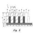
- FIG. 3 schematically shows a cross-section of the tread 4 which is being formed.
- the leftward/rightward direction corresponds to the axial direction of the tire 2
- the upward/downward direction corresponds to the radial direction of the tire 2.
- the first strip 34 and the second strip 36 are alternately wound helically, to form the tread 4. As shown in the drawings, the first strip 34 and the second strip 36 are wound such that the cross-section of the first strip 34 and the cross-section of the second strip 36 alternate in the axial direction on the cross-section of the tread 4.
- This production method is a strip winding method.
- a double-headed arrow t1 represents the thickness of the first strip 34.
- a double-headed arrow t2 represents the thickness of the second strip 36.
- a double-headed arrow W1 represents the width of the first strip 34.
- a double-headed arrow W2 represents the width of the second strip 36.
- the thickness t1 of the first strip 34 is preferably greater than or equal to 0.3 mm, and is preferably less than or equal to 3.0 mm.
- the thickness t2 of the second strip 36 is preferably greater than or equal to 0.3 mm, and is preferably less than or equal to 3.0 mm.
- the width W1 of the first strip 34 is preferably greater than or equal to 5 mm, and is preferably less than or equal to 20 mm.
- the width W2 of the second strip 36 is preferably greater than or equal to 5 mm, and is preferably less than or equal to 20 mm.
- the raw cover is put into a mold.
- the outer surface of the raw cover contacts with a cavity surface of the mold.
- the inner surface of the raw cover contacts with a bladder or a core cylinder.
- the raw cover is pressurized and heated in the mold.
- a rubber composition of the raw cover flows due to the raw cover being pressurized and heated.
- Crosslinking reaction of the rubber occurs due to the raw cover being heated, to obtain the radial tire 2.
- the first strip 34 can form the body 28 of the tread 4
- the second strip 36 can form the support portion 30 of the tread 4.
- the second strip 36 preferably has the thickness t2 that is less than the thickness t1 of the first strip 34.
- a ratio of the thickness t2 of the second strip 36 to the thickness t1 of the first strip 34 is preferably less than 1.0.
- the ratio is preferably greater than or equal to 0.2.
- the first strip 34 preferably has the width W1 that is greater than the width W2 of the second strip 36. Since the first strip 34 projects outwardly beyond the second strip 36 in the radial direction, the first strip 34 contacts with the cavity surface of the mold, and the first strip 34 is pressed in the raw cover put into the mold. Thus, the first strip 34 is squashed, and the second strip 36 is covered with the first rubber composition forming the first strip 34.
- a ratio of the width W1 of the first strip 34 to the width W2 of the second strip 36 is preferably less than or equal to 2.0.
- the ratio is preferably greater than or equal to 1.2.
- a point P represents the outermost corner of the support portion 30 in the radial direction.
- a solid line CP represents a line that is normal to the tread surface 20, and passes through the point P.
- a double-headed arrow H represents the thickness of the tread 4. The thickness H is obtained by the length from the outer surface of the band 12 to the tread surface 20 being measured along the normal line CP.
- a double-headed arrow H2 represents the height of the support portion 30. The height H2 is obtained by the length from the outer surface of the band 12 to the point P being measured along the normal line CP.
- a ratio of the height H2 of the support portion 30 to the thickness H of the tread 4 is preferably greater than or equal to 0.5, and is preferably less than 1.0.
- the ratio is set so as to be greater than or equal to 0.5, the support portions 30 can effectively contribute to the rigidity of the tire 2. The deformation of the tread 4 is appropriately reduced, so that the tire 2 can sufficiently exert the grip force.
- the ratio is set so as to be less than 1.0, the support portion 30 is assuredly covered with the body 28.
- the body 28 forms the tread surface 20, and therefore the tire 2 can stably exert the grip force.
- FIG. 4 shows an example of a portion including a groove 38 of the tire 2 shown in FIG. 1 .
- the first strip 34 is squashed, and the second strip 36 is covered with the first rubber composition forming the first strip 34. Therefore, in the tire 2 produced in this production method, the support portion 30 is not exposed even from the groove 38.
- a double-headed arrow t3 represents the thickness of the body 28 covering the support portion 30.
- the thickness t3 is represented as the length from the end surface of the support portion 30 to the bottom of the groove 38.
- the thickness t3 is preferably greater than or equal to 0.2 mm.
- the dimension and the angle in each member of the tire 2 and the tire described below are measured in a state where the tire 2 is assembled in a normal rim, and the tire 2 is filled with air so as to obtain a normal internal pressure.
- the normal rim represents a rim which is specified according to the standard with which the tire 2 complies.
- the "standard rim” in the JATMA standard, the "Design Rim” in the TRA standard, and the “Measuring Rim” in the ETRTO standard are included in the normal rim.
- the normal internal pressure represents an internal pressure which is specified according to the standard with which the tire 2 complies.
- FIG. 5 is a cross-sectional view of a portion of a pneumatic tire 40 according to another embodiment of the present invention.
- the tire 40 is of a tubeless type.
- the tire 40 is mounted to a two-wheeled vehicle.
- the upward/downward direction represents the radial direction
- the leftward/rightward direction represents the axial direction
- the direction orthogonal to the surface of the sheet represents the circumferential direction.
- the tire 40 has a shape which is almost bilaterally symmetric about an alternate long and short dash line CL shown in FIG. 5 .
- the alternate long and short dash line CL represents the equator plane of the tire 40.
- the tire 40 includes a tread 42, sidewalls 44, beads 46, a carcass 48, a band 50, wings 52, an inner liner 54, and chafers 56.
- the tire 40 has the same structure as the tire 2 shown in FIG. 1 except for the tread 42.
- the tread 42 of the tire 40 is formed of a crosslinked rubber.
- the tread 42 has a shape projecting outward in the radial direction.
- the tread 42 includes a tread surface 58.
- the tread surface 58 can contact with a road surface.
- the tread 42 includes a body 60 and multiple support portions 62 which are aligned with each other in the axial direction. Each of the support portions 62 is layered over and outside the band 50 in the radial direction. The support portion 62 extends from the inner side of the tread 42 toward the tread surface 58.
- the body 60 is formed of a first rubber composition. As shown in the drawings, the body 60 covers the support portion 62. The body 60 forms the tread surface 58. In the tire 40, the body 60 can contact with a road surface.
- a complex elastic modulus E1* of the body 60 is less than a complex elastic modulus E2* of the support portion 62.
- the body 60 is flexible.
- the body 60 which is flexible, can contribute to exertion of the grip force of the tire 40.
- the complex elastic modulus E1* of the body 60 is preferably greater than or equal to 2.5 MPa, and is preferably less than or equal to 6.0 MPa.
- the support portion 62 is formed of a second rubber composition. As shown in the drawings, the support portion 62 is formed so as to be buried in the body 60. In the tire 40, when the tread surface 58 contacts with a road surface, the body 60 is located between the road surface and the support portion 62.
- the support portion 62 has the complex elastic modulus E2* that is greater than the complex elastic modulus E1* of the body 60.
- the support portion 62 is hard.
- the support portions 62 which is hard, can contribute to rigidity of the tread 42.
- the support portion 62 can effectively reduce deformation of the surface of the tread 42. Therefore, also when a temperature of a road surface is high in summer, the tire 40 can sufficiently exert the grip force even in a long time running performed in an endurance race or the like.
- the complex elastic modulus E2* of the support portion 62 is preferably greater than or equal to 3.6 MPa, and is preferably less than equal to 12.0 MPa.
- a ratio of the complex elastic modulus E2* of the support portion 62 to the complex elastic modulus E1* of the body 60 is preferably greater than or equal to 1.2, and is more preferably greater than or equal to 1.3, and is even more preferably greater than or equal to 1.4.
- the ratio is preferably less than or equal to 2.0, and is more preferably less than or equal to 1.9, and is even more preferably less than or equal to 1.8.
- the support portion 62 extends so as to be tilted relative to the radial direction.
- the support portion 62 is tilted outward in the axial direction, from the inner side toward the outer side in the radial direction.
- the tread 42 may be structured such that the support portion 62 is tilted inward in the axial direction, from the inner side toward the outer side in the radial direction.
- a first tape-shaped strip formed of the first rubber composition and a second tape-shaped strip formed of the second rubber composition are alternately wound helically, to form the tread 42 of the tire 40.
- Each strip is wound such that the cross-section of the strip extends so as to be tilted relative to the radial direction, which is not shown.
- the tread 42 is formed that includes the support portion 62 which extends so as to be tilted relative to the radial direction.
- the first strip can form the body 60
- the second strip can form the support portion 62.
- the support portion 62 is hard.
- the second strip in order to reduce excessive increase of rigidity caused due to the support portion 62 being hard, the second strip preferably has a thickness t2 that is less than a thickness t1 of the first strip.
- a ratio of the thickness t2 of the second strip to the thickness t1 of the first strip is preferably less than 1.0.
- the ratio is preferably greater than or equal to 0.2.
- the first strip for forming the support portion 62 so as to be buried in the body 60, the first strip preferably has a width W1 that is greater than a width W2 of the second strip.
- a ratio of the width W1 of the first strip to the width W2 of the second strip is preferably less than or equal to 2.0.
- the ratio is preferably greater than or equal to 1.2.
- FIG. 6 a portion of the tire 40 shown in FIG. 5 is enlarged.
- the upward/downward direction represents the radial direction
- the leftward/rightward direction represents the axial direction
- the direction orthogonal to the surface of the sheet represents the circumferential direction.
- an alternate long and short dash line CS represents the center line of the support portion 62.
- the direction in which the center line CS extends corresponds to the direction in which the support portion 62 extends.
- an angle of the center line CS to the equator plane is represented as an angle ⁇ .
- the absolute value of the angle ⁇ corresponds to the absolute value (hereinafter, referred to as a tilt angle ⁇ ) of an angle of the direction in which the support portion 62 extends, relative to the radial direction.
- the tilt angle ⁇ of the support portion 62 is preferably set so as to be small.
- the tilt angle ⁇ is preferably less than or equal to 45 degrees, and is more preferably less than or equal to 30 degrees, and is particularly preferably less than or equal to 20 degrees.
- a point P represents the outermost corner of the support portion 62 in the radial direction.
- a solid line CP represents a line that is normal to the tread surface 58, and passes through the point P.
- a double-headed arrow H represents the thickness of the tread 42. The thickness H is obtained by the length from the outer surface of the band 50 to the tread surface 58 being measured along the normal line CP.
- a double-headed arrow H2 represents the height of the support portion 62. The height H2 is obtained by the length from the outer surface of the band 50 to the point P being measured along the normal line CP.
- a ratio of the height H2 of the support portion 62 to the thickness H of the tread 42 is preferably greater than or equal to 0.5, and is preferably less than 1.0.
- the ratio is set so as to be greater than or equal to 0.5, the support portion 62 can effectively contribute to the rigidity of the tire 40. The deformation of the tread 42 is appropriately reduced, so that the tire 40 can sufficiently exert the grip force.
- the ratio is set so as to be less than 1.0, the support portion 62 are assuredly covered with the body 60.
- the body 60 forms the tread surface 58, and therefore the tire 40 can stably exert the grip force.
- a radial tire (size: 180/55ZR17), for use in two-wheeled vehicles, having the fundamental structure shown in FIG. 5 and specifications indicated below in table 1 was obtained.
- the first strip that was formed of the first rubber composition to form the body, and the second strip that was formed of the second rubber composition to form the support portions were alternately wound helically, thereby forming a tread.
- the thickness t1 of the first strip was 2.0 mm
- the thickness t2 of the second strip was 1.5 mm. Therefore, the ratio t2/t1 of the thickness t2 to the thickness t1 was 0.75.
- the tread having been thus formed included the body and the multiple support portions that were aligned with each other in the axial direction.
- Each support portion was tilted outward in the axial direction, from the inner side toward the outer side in the radial direction. This state is represented as "X" in the cells for tilt directions in tables.
- the tilt angle ⁇ of each support portion was 20 degrees.
- the support portions were formed so as to be buried in the body.
- the ratio H2/H was 0.8, and the thickness t3 was 0.3 mm.
- the support portions each had the complex elastic modulus E2* greater than the complex elastic modulus E1* of the body.
- the complex elastic modulus E1* of the body was 3.5 MPa, and the complex elastic modulus E2* of the support portions was 5.3 MPa. Therefore, the ratio E2*/E1* was 1.5.
- Tires were each obtained so as to have the same structure as that for example 1 except that the thickness t1 and the thickness t2 were different from those for example 1, and thus the ratios t2/t1 were as indicated below in table 1 and table 2.
- Tires were each obtained so as to have the same structure as that for example 1 except that the complex elastic modulus E2* of the support portions was different from that for example 1, and thus the ratios E2*/E1* were as indicated below in table 2 and table 3.
- Tires were each obtained so as to have the same structure as that for example 1 except that the ratios H2/H were as indicated below in table 3.
- the support portions were not formed so as to be buried in the body.
- Tires were each obtained so as to have the same structure as that for example 1 except that the thicknesses t3 were as indicated below in table 4.
- Tires were each obtained so as to have the same structure as that for example 1 except that the tilt angles ⁇ were as indicated below in table 5.
- Tires were each obtained so as to have the same structure as that for example 1 except that the direction in which the support portions extended was different from that for example 1, and the tilt angles ⁇ were as indicated below in table 5.
- the support portions in examples 20 to 22 were tilted inward in the axial direction, from the inner side toward the outer side in the radial direction.
- the direction in which the support portions of example 22 were tilted was opposite to that for example 1.
- the direction in which the support portions of example 21 were tilted was opposite to that for example 24.
- the direction in which the support portions of example 20 were tilted was opposite to that for example 25.
- These states are represented as "Y" in the cells for tilt directions in table.
- a tire was obtained so as to have the same structure as that for example 1 except that the support portions were formed so as to extend in the radial direction as shown in FIG. 1 .
- the tilt angle ⁇ of each support portion in example 23 was 0 degrees.
- Tires were each obtained so as to have the same structure as that for example 1 except that the thickness t1 and the thickness t2 were different from those for example 1, and thus the ratios t2/t1 were as indicated below in table 6.
- Tires having been produced for examples were each mounted to a rear wheel of a sport-type two-wheeled vehicle (4-cycle) which had an engine displacement of 600 cc, and the tire was filled with air such that an internal pressure became 200 kPa.
- a commercially available tire (size: 120/70ZR17) was mounted to a front wheel, and the tire was filled with air such that an internal pressure became 200 kPa.
- This two-wheeled vehicle was caused to run on a circuit course having an asphalt road surface, and a sensory evaluation by a rider was made. A grip force, a rigidity, and a comprehensive performance were evaluated. The results are indicated below as indexes in table 1 to table 6. A value greater than or equal to 3.0 represents an acceptable quality.
- Example 1 Example 2 Example 3 Example 1 Example 4 Example 5 Thickness t1 [mm] - 3.0 2.5 2.0 1.8 1.6 Thickness t2 [mm] - 0.5 0.5 1.5 1.5 1.5 t2/t1 - 0.17 0.2 0.75 0.83 0.94 Complex elastic modulus E1* [MPa] - 3.5 3.5 3.5 3.5 3.5 3.5 3.5 Complex elastic modulus E2* [MPa] - 5.3 5.3 5.3 5.3 E2*/E1* - 1.5 1.5 1.5 1.5 1.5 1.5 1.5 H2/H - 0.8 0.8 0.8 0.8 Thickness t3 [mm] - 0.3 0.3 0.3 0.3 0.3 0.3 Tilt angle ⁇ [degree] - 20 20 20 20 20 20 20 20 Tilt direction - X X X X Formability A A A A A A A A A A A A A A A A A A A A A A A A A A A A A A A A A A A A A A A A A A A A A A A A A A A A A
- Example 2 Example 8
- Example 9 Example 10 Thickness t1 [mm] 1.5 1.0 2.0 2.0 2.0 2.0 Thickness t2 [mm] 1.5 1.5 1.5 1.5 1.5 1.5 1.5 t2/t1 1.0 1.5 0.75 0.75 0.75 0.75 0.75
- Complex elastic modulus E1* [MPa] 3.5 3.5 3.5 3.5 3.5 3.5 3.5
- Complex elastic modulus E2* [MPa] 5.3 5.3 2.8 4.2 4.9 5.6
- the radial tire described above is applicable to various vehicles.
- the application described above is merely an example.
Abstract
Description
- This application claims priority on Patent Application No.
2011-41171 - The present invention relates to radial tires for use in two-wheeled vehicles.
- In the viewpoint of enhancement in productivity, a tire production method is sometimes used in which strips formed of an uncrosslinked rubber are helically wound to form components such as tread, sidewalls, and the like. Such a production method may be referred to as a strip winding method. An example of this production method is disclosed in
JP2009-39883 - In consideration of enhancement of grip force, a crosslinked rubber having increased energy loss and a low complex elastic modulus is used for a tire tread in some cases. In this tread, an amount of heat generation is increased due to deformation, so that the tread is likely to be heated during running. Therefore, increase of a temperature of a road surface in summer causes excessive increase of the temperature of the tread, which is likely to soften the tread. In this case, a problem arises that the surface of the tread is excessively deformed, and the grip force cannot be sufficiently exerted.
- Similarly, also when a long time running is performed in an endurance race or the like, a temperature of a tread is excessively increased due to heat generation, so that the grip force cannot be sufficiently exerted in some cases. Therefore, in a race, plural tires having treads the hardnesses of which are different from each other are prepared, and are selectively used depending on a condition. Thus, adjustment is made such that the grip force can be sufficiently exerted in the tire.
- An object of the present invention is to make available a radial tire which is used for a two-wheeled vehicle and is capable of sufficiently exerting a grip force.
- A radial tire for use in a two-wheeled vehicle according to the present invention includes a tread having an outer surface that forms a tread surface. The tread includes a body formed of a first rubber composition, and a plurality of support portions that are formed of a second rubber composition, and that are aligned with each other in an axial direction. Each of the plurality of support portions extends from an inner side of the tread toward the tread surface. The support portion is formed so as to be buried in the body. The support portion has a complex elastic modulus E2* that is greater than a complex elastic modulus E1* of the body. The tread is formed by a first strip and a second strip being alternately wound helically. The first strip is formed of the first rubber composition of the body. The second strip is formed of the second rubber composition of the support portion.
- Preferably, in the radial tire, a ratio of the complex elastic modulus E2* to the complex elastic modulus E1* is greater than or equal to 1.2, and is less than or equal to 2.0.
- Preferably, in the radial tire, the second strip has a thickness that is less than a thickness of the first strip.
- Preferably, in the radial tire, a ratio of the thickness of the second strip to the thickness of the first strip is greater than or equal to 0.2.
- Preferably, in the radial tire, grooves are formed in the tread surface. A thickness of the body under each of the grooves is greater than or equal to 0.2 mm.
- Preferably, in the radial tire, an absolute value of an angle of a direction in which the support portion extends, relative to a radial direction, is greater than or equal to 0 degrees, and is less than or equal to 45 degrees.
- A method for producing a radial tire for use in a two-wheeled vehicle according to the present invention includes the steps of
- (1) extruding a first rubber composition to obtain a first strip;
- (2) extruding a second rubber composition to obtain a second strip;
- (3) forming a tread by the first strip and the second strip being alternately wound helically, to obtain a raw cover; and
- (4) pressurizing and heating the raw cover.
- In the radial tire obtained by this production method, the tread includes a body formed of the first rubber composition, and a plurality of support portions that are formed of the second rubber composition, and that are aligned with each other in an axial direction. Each of the plurality of support portions extends from an inner side of the tread toward a tread surface of the tread. The support portion is formed so as to be buried in the body. The support portion has a complex elastic modulus greater than a complex elastic modulus of the body.
- In the radial tire of the present invention, the body having a small complex elastic modulus E1* can contribute to exertion of grip force. In the tire, the support portion having a great complex elastic modulus E2* is formed so as to be buried in the body. The support portion can reduce excessive deformation of a surface of the tread. Also when a temperature of a road surface is increased in summer, the tire can sufficiently exert the grip force even in a long time running performed in an endurance race or the like.
-
-
FIG. 1 is a cross-sectional view illustrating a portion of a pneumatic tire according to an embodiment of the present invention; -
FIG. 2 is an enlarged cross-sectional view of a portion of the tire shown inFIG. 1 ; -
FIG. 3 is a cross-sectional view illustrating a state in which a tread of the tire shown inFIG. 1 is formed; -
FIG. 4 is an enlarged cross-sectional view of a portion including a groove of the tire shown inFIG. 1 ; -
FIG. 5 is a cross-sectional view of a portion of a pneumatic tire according to another embodiment of the present invention; and -
FIG. 6 is an enlarged cross-sectional view of a portion of the tire shown inFIG. 5 . - The following will describe in detail the present invention based on preferred embodiments with reference to the accompanying drawing.
- A
pneumatic tire 2 shown inFIG. 1 includes atread 4,sidewalls 6,beads 8, acarcass 10, aband 12,wings 14, aninner liner 16, and chafers 18. Thetire 2 is of a tubeless type. Thetire 2 is mounted to a two-wheeled vehicle(motorcycle). InFIG. 1 , the upward/downward direction represents the radial direction, the leftward/rightward direction represents the axial direction, and the direction orthogonal to the surface of the sheet represents the circumferential direction. Thetire 2 has a shape which is almost bilaterally symmetric about an alternate long and short dash line CL shown inFIG. 1 . The alternate long and short dash line CL represents the equator plane of thetire 2. - The
tread 4 is formed of a crosslinked rubber. Thetread 4 has a shape projecting outward in the radial direction. Thetread 4 includes atread surface 20. Thetread surface 20 can contact with a road surface. Grooves are formed in thetread surface 20, which is not shown. A tread pattern is formed due to the grooves. Thetread 4 may not have grooves formed therein. - The
sidewalls 6 extend from the ends, respectively, of thetread 4 approximately inward in the radial direction. Thesidewalls 6 are formed of a crosslinked rubber. Thesidewalls 6 absorb impact from a road surface due to their flexibility. Further, thesidewalls 6 prevent injury of thecarcass 10. - The
beads 8 are located approximately inwardly from thesidewalls 6, respectively, in the radial direction. Eachbead 8 includes a core 22, and an apex 24 extending from the core 22 outward in the radial direction. Thecore 22 is formed so as to be ring-shaped. Thecore 22 is formed so as to be wound with a non-extensible wire. A steel wire is typically used for thecore 22. The apex 24 is tapered outward in the radial direction. The apex 24 is formed of a highly hard crosslinked rubber. - The
carcass 10 is formed as acarcass ply 26. The carcass ply 26 extends on and between thebeads 8 located on both sides, and extends under and along thetread 4 and thesidewalls 6. The carcass ply 26 is turned up around each core 22 from the inner side to the outer side in the axial direction. - The carcass ply 26 is formed of multiple cords aligned with each other, and a topping rubber, which is not shown. An absolute value of an angle of each cord relative to the equator plane usually ranges from 70 degrees to 90 degrees. In other words, the
carcass 10 has a radial structure. Thetire 2 is superior, in high-speed durability, to tires having carcasses of a bias structure. The cords are typically formed of an organic fiber. Examples of preferable organic fiber include polyester fibers, nylon fibers, rayon fibers, polyethylene naphthalate fibers, and aramid fibers. - The
band 12 is located inwardly from thetread 4 in the radial direction. Theband 12 is located outwardly of thecarcass 10 in the radial direction. Theband 12 is layered over thecarcass 10. Theband 12 includes a cord and a topping rubber, which is not shown. The cord extends substantially in the circumferential direction, and is helically wound. Theband 12 has a so-called jointless structure. Theband 12 can contribute to rigidity of thetire 2 in the radial direction. Thus, an influence of the centrifugal force exerted during running is reduced. The cord is typically formed of an organic fiber. Examples of preferable organic fiber include nylon fibers, polyester fibers, rayon fibers, polyethylene naphthalate fibers, and aramid fibers. - In the
tire 2, thetread 4 includes abody 28 and a plurality of thesupport portions 30 which are aligned with each other in the axial direction. Each of the plurality of thesupport portions 30 is layered over and outside theband 12 in the radial direction. Thesupport portion 30 extends from the inner side of thetread 4 toward thetread surface 20. - In the
tire 2, thebody 28 is formed of a first rubber composition. As shown in the drawings, thebody 28 covers thesupport portion 30. Thebody 28 forms thetread surface 20. In thetire 2, thebody 28 can contact with a road surface. - In the
tire 2, a complex elastic modulus E1* of thebody 28 is less than a complex elastic modulus E2* of thesupport portion 30. Thebody 28 is flexible. Thebody 28, which is flexible, can contribute to exertion of the grip force of thetire 2. In this viewpoint, the complex elastic modulus E1* of thebody 28 is preferably greater than or equal to 2.5 MPa, and is preferably less than or equal to 6.0 MPa. - In the present invention, the complex elastic modulus E1* of the
body 28 and the complex elastic modulus E2* of thesupport portion 30 are measured, in compliance with the standard of "JIS K 6394", by using a viscoelasticity spectrometer (manufactured by Iwamoto Seisakusho), under the following conditions.
Initial strain: 10%
Amplitude: ±2.5%
Frequency: 10 Hz
Deformation mode: tension
Measurement temperature: 100°C - In the
tire 2, thesupport portion 30 is formed of a second rubber composition. As shown in the drawings, thesupport portion 30 is formed so as to be buried in thebody 28. In other words, thebody 28 is located outwardly of thesupport portion 30 in the radial direction. In thetire 2, when thetread surface 20 contacts with a road surface, thebody 28 is located between the road surface and thesupport portion 30. - In the
tire 2, thesupport portion 30 has the complex elastic modulus E2* that is greater than the complex elastic modulus E1* of thebody 28. Thesupport portion 30 is hard. Thesupport portion 30, which is hard, can contribute to rigidity of thetread 4. Thesupport portion 30 can effectively reduce deformation of the surface of thetread 4. Therefore, also when a temperature of a road surface is high in summer, thetire 2 can sufficiently exert the grip force even in a long time running performed in an endurance race or the like. In this viewpoint, the complex elastic modulus E2* of thesupport portion 30 is preferably greater than or equal to 3.6 MPa, and is preferably less than or equal to 12.0 MPa. - In the
tire 2, in order to enable thesupport portion 30 to contribute to reduction of deformation of the surface of thetread 4, and enable thebody 28 to contribute to exertion of the grip force, a ratio of the complex elastic modulus E2* of thesupport portion 30 to the complex elastic modulus E1* of thebody 28 is preferably greater than or equal to 1.2, and is more preferably greater than or equal to 1.3, and is even more preferably greater than or equal to 1.4. The ratio is preferably less than or equal to 2.0, and is more preferably less than or equal to 1.9, and is even more preferably less than or equal to 1.8. - In
FIG. 2 , a portion of thetire 2 shown inFIG. 1 is enlarged. InFIG. 2 , the upward/downward direction represents the radial direction, the leftward/rightward direction represents the axial direction, and the direction orthogonal to the surface of the sheet represents the circumferential direction. InFIG. 2 , an alternate long and short dash line CS represents the center line of thesupport portion 30. Thesupport portion 30 includes a pair of side surfaces 32 that extend from the inner side of thetread 4 toward thetread surface 20. The center line CS extends through the midpoints between both side surfaces 32. In the description herein, the direction in which the center line CS extends corresponds to the direction in which thesupport portion 30 extends. The absolute value of an angle of the center line CS relative to the equator plane corresponds to the absolute value (hereinafter, referred to as a tilt angle) of an angle of the direction in which thesupport portion 30 extends, relative to the radial direction. - In the
tire 2, in order to enable thesupport portion 30 to effectively contribute to the rigidity, the tilt angle of thesupport portion 30 is preferably set so as to be small. In this viewpoint, the tilt angle is preferably less than or equal to 45 degrees, and is more preferably less than or equal to 30 degrees, and is particularly preferably less than or equal to 20 degrees. When the center line CS extends parallel to the equator plane, that is, when the center line CS extends in the radial direction, the tilt angle indicates the lower limit value (0 degrees) thereof. - As shown in the drawings, the center line CS of
support portion 30 extends in the radial direction. In thetire 2, the tilt angle of thesupport portion 30 is 0 degrees. - The
tire 2 is produced in the following manner. The first rubber composition is extruded, to obtain a first strip which is tape-shaped. The second rubber composition is extruded, to obtain a second strip which is tape-shaped. The first strip and the second strip are put in a former (not shown) together with other components. In the former, these components are combined with each other. - In the former, the
inner liner 16 which is sheet-shaped is wound around a drum, and, thereafter, the carcass ply 26 which is also sheet-shaped is wound. Further, a band component formed of a cord and a topping rubber is helically wound over and around the carcass ply 26 which has been formed in a cylindrical shape, thereby forming theband 12. Thetread 4 is formed by using the first strip and the second strip. Thus, a raw cover (unvulcanized tire) is obtained. -
FIG. 3 schematically shows a cross-section of thetread 4 which is being formed. InFIG. 3 , the leftward/rightward direction corresponds to the axial direction of thetire 2, and the upward/downward direction corresponds to the radial direction of thetire 2. - In this production method, the
first strip 34 and thesecond strip 36 are alternately wound helically, to form thetread 4. As shown in the drawings, thefirst strip 34 and thesecond strip 36 are wound such that the cross-section of thefirst strip 34 and the cross-section of thesecond strip 36 alternate in the axial direction on the cross-section of thetread 4. This production method is a strip winding method. - In
FIG. 3 , a double-headed arrow t1 represents the thickness of thefirst strip 34. A double-headed arrow t2 represents the thickness of thesecond strip 36. A double-headed arrow W1 represents the width of thefirst strip 34. A double-headed arrow W2 represents the width of thesecond strip 36. - In this production method, in order to facilitate the forming, the thickness t1 of the
first strip 34 is preferably greater than or equal to 0.3 mm, and is preferably less than or equal to 3.0 mm. In the same viewpoint, the thickness t2 of thesecond strip 36 is preferably greater than or equal to 0.3 mm, and is preferably less than or equal to 3.0 mm. - In this production method, in order to facilitate the forming, the width W1 of the
first strip 34 is preferably greater than or equal to 5 mm, and is preferably less than or equal to 20 mm. In the same viewpoint, the width W2 of thesecond strip 36 is preferably greater than or equal to 5 mm, and is preferably less than or equal to 20 mm. - In this production method, the raw cover is put into a mold. Thus, the outer surface of the raw cover contacts with a cavity surface of the mold. The inner surface of the raw cover contacts with a bladder or a core cylinder. The raw cover is pressurized and heated in the mold. A rubber composition of the raw cover flows due to the raw cover being pressurized and heated. Crosslinking reaction of the rubber occurs due to the raw cover being heated, to obtain the
radial tire 2. In thetire 2 having been thus produced, thefirst strip 34 can form thebody 28 of thetread 4, and thesecond strip 36 can form thesupport portion 30 of thetread 4. - In this production method, as shown in
FIG. 3 , thesecond strip 36 preferably has the thickness t2 that is less than the thickness t1 of thefirst strip 34. In other words, a ratio of the thickness t2 of thesecond strip 36 to the thickness t1 of thefirst strip 34 is preferably less than 1.0. Thus, excessive increase of rigidity caused due to thesupport portions 30 being hard can be reduced. In order to enable thesupport portion 30 to appropriately contribute to reduction of deformation of the surface of thetread 4, the ratio is preferably greater than or equal to 0.2. - In this production method, as shown in
FIG. 3 , thefirst strip 34 preferably has the width W1 that is greater than the width W2 of thesecond strip 36. Since thefirst strip 34 projects outwardly beyond thesecond strip 36 in the radial direction, thefirst strip 34 contacts with the cavity surface of the mold, and thefirst strip 34 is pressed in the raw cover put into the mold. Thus, thefirst strip 34 is squashed, and thesecond strip 36 is covered with the first rubber composition forming thefirst strip 34. - In this production method, for forming the
support portion 30 so as to be buried in thebody 28, a ratio of the width W1 of thefirst strip 34 to the width W2 of thesecond strip 36 is preferably less than or equal to 2.0. In order to enable thesupport portion 30 to appropriately contribute to reduction of deformation of the surface of thetread 4, the ratio is preferably greater than or equal to 1.2. - In
FIG. 2 , a point P represents the outermost corner of thesupport portion 30 in the radial direction. A solid line CP represents a line that is normal to thetread surface 20, and passes through the point P. A double-headed arrow H represents the thickness of thetread 4. The thickness H is obtained by the length from the outer surface of theband 12 to thetread surface 20 being measured along the normal line CP. A double-headed arrow H2 represents the height of thesupport portion 30. The height H2 is obtained by the length from the outer surface of theband 12 to the point P being measured along the normal line CP. - In the
tire 2, a ratio of the height H2 of thesupport portion 30 to the thickness H of thetread 4 is preferably greater than or equal to 0.5, and is preferably less than 1.0. When the ratio is set so as to be greater than or equal to 0.5, thesupport portions 30 can effectively contribute to the rigidity of thetire 2. The deformation of thetread 4 is appropriately reduced, so that thetire 2 can sufficiently exert the grip force. When the ratio is set so as to be less than 1.0, thesupport portion 30 is assuredly covered with thebody 28. Thus, thebody 28 forms thetread surface 20, and therefore thetire 2 can stably exert the grip force. -
FIG. 4 shows an example of a portion including agroove 38 of thetire 2 shown inFIG. 1 . As described above, in this production method, thefirst strip 34 is squashed, and thesecond strip 36 is covered with the first rubber composition forming thefirst strip 34. Therefore, in thetire 2 produced in this production method, thesupport portion 30 is not exposed even from thegroove 38. - In
FIG. 4 , a double-headed arrow t3 represents the thickness of thebody 28 covering thesupport portion 30. The thickness t3 is represented as the length from the end surface of thesupport portion 30 to the bottom of thegroove 38. In thetire 2, the thickness t3 is preferably greater than or equal to 0.2 mm. Thus, generation of a crack due to thesupport portion 30 being exposed can be effectively prevented. - In the present invention, the dimension and the angle in each member of the
tire 2 and the tire described below are measured in a state where thetire 2 is assembled in a normal rim, and thetire 2 is filled with air so as to obtain a normal internal pressure. During the measurement, no load is applied to thetire 2. In the description of the present invention, the normal rim represents a rim which is specified according to the standard with which thetire 2 complies. The "standard rim" in the JATMA standard, the "Design Rim" in the TRA standard, and the "Measuring Rim" in the ETRTO standard are included in the normal rim. In the description of the present invention, the normal internal pressure represents an internal pressure which is specified according to the standard with which thetire 2 complies. The "maximum air pressure" in the JATMA standard, the "maximum value" recited in "TIRE LOAD LIMITS AT VARIOUS COLD INFLATION PRESSURES" in the TRA standard, and the "INFLATION PRESSURE" in the ETRTO standard are included in the normal internal pressure. -
FIG. 5 is a cross-sectional view of a portion of apneumatic tire 40 according to another embodiment of the present invention. Thetire 40 is of a tubeless type. Thetire 40 is mounted to a two-wheeled vehicle. InFIG. 5 , the upward/downward direction represents the radial direction, the leftward/rightward direction represents the axial direction, and the direction orthogonal to the surface of the sheet represents the circumferential direction. Thetire 40 has a shape which is almost bilaterally symmetric about an alternate long and short dash line CL shown inFIG. 5 . The alternate long and short dash line CL represents the equator plane of thetire 40. - The
tire 40 includes atread 42, sidewalls 44,beads 46, acarcass 48, aband 50,wings 52, aninner liner 54, andchafers 56. Thetire 40 has the same structure as thetire 2 shown inFIG. 1 except for thetread 42. - The
tread 42 of thetire 40 is formed of a crosslinked rubber. Thetread 42 has a shape projecting outward in the radial direction. Thetread 42 includes atread surface 58. Thetread surface 58 can contact with a road surface. - The
tread 42 includes abody 60 andmultiple support portions 62 which are aligned with each other in the axial direction. Each of thesupport portions 62 is layered over and outside theband 50 in the radial direction. Thesupport portion 62 extends from the inner side of thetread 42 toward thetread surface 58. - In the
tire 40, thebody 60 is formed of a first rubber composition. As shown in the drawings, thebody 60 covers thesupport portion 62. Thebody 60 forms thetread surface 58. In thetire 40, thebody 60 can contact with a road surface. - In the
tire 40, a complex elastic modulus E1* of thebody 60 is less than a complex elastic modulus E2* of thesupport portion 62. Thebody 60 is flexible. Thebody 60, which is flexible, can contribute to exertion of the grip force of thetire 40. In this viewpoint, the complex elastic modulus E1* of thebody 60 is preferably greater than or equal to 2.5 MPa, and is preferably less than or equal to 6.0 MPa. - In the
tire 40, thesupport portion 62 is formed of a second rubber composition. As shown in the drawings, thesupport portion 62 is formed so as to be buried in thebody 60. In thetire 40, when thetread surface 58 contacts with a road surface, thebody 60 is located between the road surface and thesupport portion 62. - In the
tire 40, thesupport portion 62 has the complex elastic modulus E2* that is greater than the complex elastic modulus E1* of thebody 60. Thesupport portion 62 is hard. Thesupport portions 62, which is hard, can contribute to rigidity of thetread 42. Thesupport portion 62 can effectively reduce deformation of the surface of thetread 42. Therefore, also when a temperature of a road surface is high in summer, thetire 40 can sufficiently exert the grip force even in a long time running performed in an endurance race or the like. In this viewpoint, the complex elastic modulus E2* of thesupport portion 62 is preferably greater than or equal to 3.6 MPa, and is preferably less than equal to 12.0 MPa. - In the
tire 40, in order to enable thesupport portion 62 to contribute to reduction of deformation of the surface of thetread 42, and enable thebody 60 to contribute to exertion of the grip force, a ratio of the complex elastic modulus E2* of thesupport portion 62 to the complex elastic modulus E1* of thebody 60 is preferably greater than or equal to 1.2, and is more preferably greater than or equal to 1.3, and is even more preferably greater than or equal to 1.4. The ratio is preferably less than or equal to 2.0, and is more preferably less than or equal to 1.9, and is even more preferably less than or equal to 1.8. - As shown in the drawings, the
support portion 62 extends so as to be tilted relative to the radial direction. In thetire 40, thesupport portion 62 is tilted outward in the axial direction, from the inner side toward the outer side in the radial direction. Alternatively, thetread 42 may be structured such that thesupport portion 62 is tilted inward in the axial direction, from the inner side toward the outer side in the radial direction. - Similarly to the
tire 2 shown inFIG. 1 , a first tape-shaped strip formed of the first rubber composition and a second tape-shaped strip formed of the second rubber composition are alternately wound helically, to form thetread 42 of thetire 40. Each strip is wound such that the cross-section of the strip extends so as to be tilted relative to the radial direction, which is not shown. Thus, thetread 42 is formed that includes thesupport portion 62 which extends so as to be tilted relative to the radial direction. Also in thetire 40, similarly to thetire 2 shown inFIG. 1 , the first strip can form thebody 60, and the second strip can form thesupport portion 62. - As described above, the
support portion 62 is hard. In this production method, in order to reduce excessive increase of rigidity caused due to thesupport portion 62 being hard, the second strip preferably has a thickness t2 that is less than a thickness t1 of the first strip. In other words, a ratio of the thickness t2 of the second strip to the thickness t1 of the first strip is preferably less than 1.0. In order to enable thesupport portion 62 to appropriately contribute to reduction of deformation of the surface of thetread 42, the ratio is preferably greater than or equal to 0.2. - In this production method, for forming the
support portion 62 so as to be buried in thebody 60, the first strip preferably has a width W1 that is greater than a width W2 of the second strip. In other words, a ratio of the width W1 of the first strip to the width W2 of the second strip is preferably less than or equal to 2.0. In order to enable thesupport portion 62 to appropriately contribute to reduction of deformation of the surface of thetread 42, the ratio is preferably greater than or equal to 1.2. - In
FIG. 6 , a portion of thetire 40 shown inFIG. 5 is enlarged. InFIG. 6 , the upward/downward direction represents the radial direction, the leftward/rightward direction represents the axial direction, and the direction orthogonal to the surface of the sheet represents the circumferential direction. InFIG. 6 , an alternate long and short dash line CS represents the center line of thesupport portion 62. The direction in which the center line CS extends corresponds to the direction in which thesupport portion 62 extends. InFIG. 6 , an angle of the center line CS to the equator plane is represented as an angle α. The absolute value of the angle α corresponds to the absolute value (hereinafter, referred to as a tilt angle α) of an angle of the direction in which thesupport portion 62 extends, relative to the radial direction. - In the
tire 40, in order to enable thesupport portion 62 to effectively contribute to the rigidity, the tilt angle α of thesupport portion 62 is preferably set so as to be small. In this viewpoint, the tilt angle α is preferably less than or equal to 45 degrees, and is more preferably less than or equal to 30 degrees, and is particularly preferably less than or equal to 20 degrees. - In
FIG. 6 , a point P represents the outermost corner of thesupport portion 62 in the radial direction. A solid line CP represents a line that is normal to thetread surface 58, and passes through the point P. A double-headed arrow H represents the thickness of thetread 42. The thickness H is obtained by the length from the outer surface of theband 50 to thetread surface 58 being measured along the normal line CP. A double-headed arrow H2 represents the height of thesupport portion 62. The height H2 is obtained by the length from the outer surface of theband 50 to the point P being measured along the normal line CP. - In the
tire 40, a ratio of the height H2 of thesupport portion 62 to the thickness H of thetread 42 is preferably greater than or equal to 0.5, and is preferably less than 1.0. When the ratio is set so as to be greater than or equal to 0.5, thesupport portion 62 can effectively contribute to the rigidity of thetire 40. The deformation of thetread 42 is appropriately reduced, so that thetire 40 can sufficiently exert the grip force. When the ratio is set so as to be less than 1.0, thesupport portion 62 are assuredly covered with thebody 60. Thus, thebody 60 forms thetread surface 58, and therefore thetire 40 can stably exert the grip force. - Hereinafter, effects of the present invention will become apparent according to examples. However, the present invention should not be restrictively construed based on the description of examples.
- A radial tire (size: 180/55ZR17), for use in two-wheeled vehicles, having the fundamental structure shown in
FIG. 5 and specifications indicated below in table 1 was obtained. In the production of the tire, the first strip that was formed of the first rubber composition to form the body, and the second strip that was formed of the second rubber composition to form the support portions were alternately wound helically, thereby forming a tread. The thickness t1 of the first strip was 2.0 mm, and the thickness t2 of the second strip was 1.5 mm. Therefore, the ratio t2/t1 of the thickness t2 to the thickness t1 was 0.75. The tread having been thus formed included the body and the multiple support portions that were aligned with each other in the axial direction. Each support portion was tilted outward in the axial direction, from the inner side toward the outer side in the radial direction. This state is represented as "X" in the cells for tilt directions in tables. The tilt angle α of each support portion was 20 degrees. The support portions were formed so as to be buried in the body. The ratio H2/H was 0.8, and the thickness t3 was 0.3 mm. The support portions each had the complex elastic modulus E2* greater than the complex elastic modulus E1* of the body. The complex elastic modulus E1* of the body was 3.5 MPa, and the complex elastic modulus E2* of the support portions was 5.3 MPa. Therefore, the ratio E2*/E1* was 1.5. - Tires were each obtained so as to have the same structure as that for example 1 except that the thickness t1 and the thickness t2 were different from those for example 1, and thus the ratios t2/t1 were as indicated below in table 1 and table 2.
- Tires were each obtained so as to have the same structure as that for example 1 except that the complex elastic modulus E2* of the support portions was different from that for example 1, and thus the ratios E2*/E1* were as indicated below in table 2 and table 3.
- Tires were each obtained so as to have the same structure as that for example 1 except that the ratios H2/H were as indicated below in table 3. In comparative example 3, the support portions were not formed so as to be buried in the body.
- Tires were each obtained so as to have the same structure as that for example 1 except that the thicknesses t3 were as indicated below in table 4.
- Tires were each obtained so as to have the same structure as that for example 1 except that the tilt angles α were as indicated below in table 5.
- Tires were each obtained so as to have the same structure as that for example 1 except that the direction in which the support portions extended was different from that for example 1, and the tilt angles α were as indicated below in table 5. The support portions in examples 20 to 22 were tilted inward in the axial direction, from the inner side toward the outer side in the radial direction. The direction in which the support portions of example 22 were tilted was opposite to that for example 1. The direction in which the support portions of example 21 were tilted was opposite to that for example 24. The direction in which the support portions of example 20 were tilted was opposite to that for example 25. These states are represented as "Y" in the cells for tilt directions in table.
- A tire was obtained so as to have the same structure as that for example 1 except that the support portions were formed so as to extend in the radial direction as shown in
FIG. 1 . The tilt angle α of each support portion in example 23 was 0 degrees. - Tires were each obtained so as to have the same structure as that for example 1 except that the thickness t1 and the thickness t2 were different from those for example 1, and thus the ratios t2/t1 were as indicated below in table 6.
- 1000 tires were produced, and formability thereof was evaluated. The results are indicated below in table 1 to table 6. In tables, "A" represents a case where the tires were stably produced, "B" represents a case where although the tires were produced, some improvement in the production process steps was needed, and "C" represents a case where a trouble occurred during production, and the tires were not able to be stably produced.
- Tires having been produced for examples were each mounted to a rear wheel of a sport-type two-wheeled vehicle (4-cycle) which had an engine displacement of 600 cc, and the tire was filled with air such that an internal pressure became 200 kPa. A commercially available tire (size: 120/70ZR17) was mounted to a front wheel, and the tire was filled with air such that an internal pressure became 200 kPa. This two-wheeled vehicle was caused to run on a circuit course having an asphalt road surface, and a sensory evaluation by a rider was made. A grip force, a rigidity, and a comprehensive performance were evaluated. The results are indicated below as indexes in table 1 to table 6. A value greater than or equal to 3.0 represents an acceptable quality. In examples 16 to 19, bottom portions of grooves of the tires were observed after running, to check for presence or absence of a crack. The results are indicated below in table 4. In table 4, "G" represents a case where no crack was found, "NG" represents a case where a crack was found.
Table 1 Evaluation results Comp. example 1 Example 2 Example 3 Example 1 Example 4 Example 5 Thickness t1 [mm] - 3.0 2.5 2.0 1.8 1.6 Thickness t2 [mm] - 0.5 0.5 1.5 1.5 1.5 t2/t1 - 0.17 0.2 0.75 0.83 0.94 Complex elastic modulus E1* [MPa] - 3.5 3.5 3.5 3.5 3.5 Complex elastic modulus E2* [MPa] - 5.3 5.3 5.3 5.3 5.3 E2*/E1* - 1.5 1.5 1.5 1.5 1.5 H2/H - 0.8 0.8 0.8 0.8 0.8 Thickness t3 [mm] - 0.3 0.3 0.3 0.3 0.3 Tilt angle α [degree] - 20 20 20 20 20 Tilt direction - X X X X X Formability A A A A A A Grip force 4.5 4.0 3.5 4.5 4.2 3.8 Rigidity 2.0 3.0 3.5 4.5 4.6 4.7 Comprehensive evaluation 2.0 3.0 3.5 4.5 4.2 3.8 Table 2 Evaluation results Example 6 Example 7 Comp. example 2 Example 8 Example 9 Example 10 Thickness t1 [mm] 1.5 1.0 2.0 2.0 2.0 2.0 Thickness t2 [mm] 1.5 1.5 1.5 1.5 1.5 1.5 t2/t1 1.0 1.5 0.75 0.75 0.75 0.75 Complex elastic modulus E1* [MPa] 3.5 3.5 3.5 3.5 3.5 3.5 Complex elastic modulus E2* [MPa] 5.3 5.3 2.8 4.2 4.9 5.6 E2*/E1* 1.5 1.5 0.8 1.2 1.4 1.6 H2/H 0.8 0.8 0.8 0.8 0.8 0.8 Thickness t3 [mm] 0.3 0.3 0.3 0.3 0.3 0.3 Tilt angle α [degree] 20 20 20 20 20 20 Tilt direction X X X X X X Formability A A A A A A Grip force 3.5 2.5 4.0 4.1 4.3 4.5 Rigidity 4.9 5.0 2.0 3.5 4.0 4.5 Comprehensive evaluation 3.5 3.0 2.0 3.5 4.0 4.5 Table 3 Evaluation results Example 11 Example 12 Example 13 Example 14 Example 15 Comp. example 3 Thickness t1 [mm] 2.0 2.0 2.0 2.0 2.0 2.0 Thickness t2 [mm] 1.5 1.5 1.5 1.5 1.5 1.5 t2/t1 0.75 0.75 0.75 0.75 0.75 0.75 Complex elastic modulus E1* [MPa] 3.5 3.5 3.5 3.5 3.5 3.5 Complex elastic modulus E2* [MPa] 6.3 7.0 8.75 5.3 5.3 5.3 E2*/E1* 1.8 2.0 2.5 1.5 1.5 1.5 H2/H 0.8 0.8 0.8 0.3 0.5 1.0 Thickness t3 [mm] 0.3 0.3 0.3 0.3 0.3 0.3 Tilt angle α [degree] 20 20 20 20 20 20 Tilt direction X X X X X X Formability A A A A A A Grip force 4.0 3.5 2.5 4.0 4.3 3.5 Rigidity 4.8 5.0 5.0 2.5 3.5 5.0 Comprehensive evaluation 4.0 3.5 3.0 3.0 3.5 3.5 Table 4 Evaluation results Example 16 Example 17 Example 18 Example 19 Thickness t1 [mm] 2.0 2.0 2.0 2.0 Thickness t2 [mm] 1.5 1.5 1.5 1.5 t2/t1 0.75 0.75 0.75 0.75 Complex elastic modulus E1* [MPa] 3.5 3.5 3.5 3.5 Complex elastic modulus E2* [MPa] 5.3 5.3 5.3 5.3 E2*/E1* 1.5 1.5 1.5 1.5 H2/H 0.8 0.8 0.8 0.8 Thickness t3 [mm] 0.1 0.2 0.5 1.0 Tilt angle α [degree] 20 20 20 20 Tilt direction X X X X Formability A A A A Grip force 4.5 4.5 4.5 4.5 Rigidity 4.5 4.5 4.5 4.5 Comprehensive evaluation 4.5 4.5 4.5 4.5 Crack NG G G G Table 5 Evaluation results Example 20 Example 21 Example 22 Example 23 Example 24 Example 25 Thickness t1 [mm] 2.0 2.0 2.0 2.0 2.0 2.0 Thickness t2 [mm] 1.5 1.5 1.5 1.5 1.5 1.5 t2/t1 0.75 0.75 0.75 0.75 0.75 0.75 Complex elastic modulus E1* [MPa] 3.5 3.5 3.5 3.5 3.5 3.5 Complex elastic modulus E2* [MPa] 5.3 5.3 5.3 5.3 5.3 5.3 E2*/E1* 1.5 1.5 1.5 1.5 1.5 1.5 H2/H 0.8 0.8 0.8 0.8 0.8 0.8 Thickness t3 [mm] 0.3 0.3 0.3 0.3 0.3 0.3 Tilt angle α [degree] 60 45 20 0 45 60 Tilt direction Y Y Y - X X Formability C A A A A C Grip force 2.5 3.0 3.3 4.0 4.0 3.5 Rigidity 5.0 5.0 5.0 4.8 3.5 3.0 Comprehensive evaluation 3.0 3.2 3.3 4.0 3.5 3.0 Table 6 Evaluation results Example 26 Example 27 Example 28 Example 29 Example 30 Example 31 Thickness t1 [mm] 3.0 3.0 3.0 2.0 1.0 0.6 Thickness t2 [mm] 0.6 1.5 2.5 0.5 0.5 0.5 t2/t1 0.2 0.5 0.83 0.25 0.5 0.83 Complex elastic modulus E1* [MPa] 3.5 3.5 3.5 3.5 3.5 3.5 Complex elastic modulus E2* [MPa] 5.3 5.3 5.3 5.3 5.3 5.3 E2*/E1* 1.5 1.5 1.5 1.5 1.5 1.5 H2/H 0.8 0.8 0.8 0.8 0.8 0.8 Thickness t3 [mm] 0.3 0.3 0.3 0.3 0.3 0.3 Tilt angle α [degree] 20 20 20 20 20 20 Tilt direction X X X X X X Formability B B B B B B Grip force 3.5 4.0 4.2 3.6 4.0 4.2 Rigidity 3.5 4.0 4.6 3.6 4.0 4.6 Comprehensive evaluation 3.5 4.0 4.2 3.6 4.0 4.2 - As indicated in table 1 to table 6, evaluations for the tires of examples are higher than evaluations for the tires of comparative examples. These evaluation results clearly indicate that the present invention is superior.
- The radial tire described above is applicable to various vehicles. The application described above is merely an example.
- The foregoing description is in all aspects illustrative, and various modifications can be devised without departing from the essential features of the invention.
Claims (7)
- A radial tire for use in a two-wheeled vehicle, the radial tire comprising:a tread having an outer surface that forms a tread surface, whereinthe tread includes a body formed of a first rubber composition, and a plurality of support portions that are formed of a second rubber composition, and that are aligned with each other in an axial direction,each of the plurality of support portions extends from an inner side of the tread toward the tread surface,the support portion is formed so as to be buried in the body,the support portion has a complex elastic modulus E2* that is greater than a complex elastic modulus E1* of the body,the tread is formed by a first strip and a second strip being alternately wound helically,the first strip is formed of the first rubber composition of the body, andthe second strip is formed of the second rubber composition of the support portion.
- The radial tire according to claim 1, wherein a ratio of the complex elastic modulus E2* to the complex elastic modulus E1* is greater than or equal to 1.2, and is less than or equal to 2.0.
- The radial tire according to claim 1, wherein the second strip has a thickness that is less than a thickness of the first strip.
- The radial tire according to claim 3, wherein a ratio of the thickness of the second strip to the thickness of the first strip is greater than or equal to 0.2.
- The radial tire according to claim 1, wherein
a groove is formed in the tread surface, and
a thickness of the body under the groove is greater than or equal to 0.2 mm. - The radial tire according to claim 1, wherein an absolute value of an angle of a direction in which the support portion extends, relative to a radial direction, is greater than or equal to 0 degrees, and is less than or equal to 45 degrees.
- A method for producing a radial tire for use in a two-wheeled vehicle, the method comprising the steps of:extruding a first rubber composition to obtain a first strip;extruding a second rubber composition to obtain a second strip;forming a tread by the first strip and the second strip being alternately wound helically, to obtain a raw cover; andpressurizing and heating the raw cover, whereinin the radial tire obtained by the pressurizing and heating, the tread includes a body formed of the first rubber composition, and a plurality of support portions that are formed of the second rubber composition, and that are aligned with each other in an axial direction,each of the plurality of support portions extends from an inner side of the tread toward a tread surface of the tread,the support portion is formed so as to be buried in the body, and has a complex elastic modulus greater than a complex elastic modulus of the body.
Applications Claiming Priority (1)
| Application Number | Priority Date | Filing Date | Title |
|---|---|---|---|
| JP2011041171A JP5297485B2 (en) | 2011-02-28 | 2011-02-28 | Radial tires for motorcycles |
Publications (3)
| Publication Number | Publication Date |
|---|---|
| EP2492115A2 true EP2492115A2 (en) | 2012-08-29 |
| EP2492115A3 EP2492115A3 (en) | 2013-04-17 |
| EP2492115B1 EP2492115B1 (en) | 2014-09-03 |
Family
ID=45476402
Family Applications (1)
| Application Number | Title | Priority Date | Filing Date |
|---|---|---|---|
| EP12000087.2A Not-in-force EP2492115B1 (en) | 2011-02-28 | 2012-01-09 | Radial tire for use in two-wheeled vehicle |
Country Status (4)
| Country | Link |
|---|---|
| US (1) | US20120216934A1 (en) |
| EP (1) | EP2492115B1 (en) |
| JP (1) | JP5297485B2 (en) |
| CN (1) | CN102649387B (en) |
Families Citing this family (3)
| Publication number | Priority date | Publication date | Assignee | Title |
|---|---|---|---|---|
| JP6291367B2 (en) * | 2014-06-25 | 2018-03-14 | 住友ゴム工業株式会社 | Pneumatic tire |
| DE102015207937A1 (en) * | 2015-04-29 | 2016-11-03 | Continental Reifen Deutschland Gmbh | Pneumatic vehicle tire with a tread |
| DE102015207931A1 (en) * | 2015-04-29 | 2016-11-03 | Continental Reifen Deutschland Gmbh | Pneumatic vehicle tire with a tread |
Citations (2)
| Publication number | Priority date | Publication date | Assignee | Title |
|---|---|---|---|---|
| JP2009039883A (en) | 2007-08-06 | 2009-02-26 | Sumitomo Rubber Ind Ltd | Studless tire and its manufacturing method |
| JP2011041171A (en) | 2009-08-18 | 2011-02-24 | Panasonic Corp | Radio communication terminal |
Family Cites Families (19)
| Publication number | Priority date | Publication date | Assignee | Title |
|---|---|---|---|---|
| US4478266A (en) * | 1982-09-17 | 1984-10-23 | The Goodyear Tire & Rubber Company | Composite tread having good traction and reduced rolling resistance upon wear |
| JPS62196704U (en) * | 1986-06-05 | 1987-12-14 | ||
| JPS63134311A (en) * | 1986-11-26 | 1988-06-06 | Yokohama Rubber Co Ltd:The | Pneumatic tire for motorcycle |
| JP3012686B2 (en) * | 1990-11-29 | 2000-02-28 | 株式会社ブリヂストン | Pneumatic radial tire |
| DE19718701C1 (en) * | 1997-05-02 | 1998-06-10 | Continental Ag | Production of vehicular tyres by winding strips of material onto pre-expanded tyre base |
| JP3352045B2 (en) * | 1999-03-04 | 2002-12-03 | 住友ゴム工業株式会社 | Rubber strip for forming tire rubber member, tire using the same, and rubber strip manufacturing apparatus |
| JP4011382B2 (en) * | 2002-04-03 | 2007-11-21 | 住友ゴム工業株式会社 | Pneumatic tire |
| JP4290475B2 (en) * | 2003-05-16 | 2009-07-08 | 東洋ゴム工業株式会社 | Pneumatic tire and method for manufacturing the pneumatic tire |
| JP4753342B2 (en) * | 2003-10-27 | 2011-08-24 | 株式会社ブリヂストン | Pneumatic radial tire |
| JP4312613B2 (en) * | 2004-01-19 | 2009-08-12 | 東洋ゴム工業株式会社 | Pneumatic tire |
| JP4255435B2 (en) * | 2004-11-11 | 2009-04-15 | 住友ゴム工業株式会社 | Pneumatic tire manufacturing method |
| JP2006168564A (en) * | 2004-12-16 | 2006-06-29 | Bridgestone Corp | Pneumatic tire |
| JP4974695B2 (en) * | 2007-02-01 | 2012-07-11 | 株式会社ブリヂストン | Motorcycle tires |
| JP4713515B2 (en) * | 2007-02-16 | 2011-06-29 | 株式会社ブリヂストン | Pneumatic tire |
| US20080216930A1 (en) * | 2007-03-05 | 2008-09-11 | Christopher John Valentine | Tyre with rubber tread which contains internal circumferential rubber stabilizer bars |
| JP4889032B2 (en) * | 2007-03-08 | 2012-02-29 | 株式会社ブリヂストン | Pneumatic tires for motorcycles |
| JP2009035228A (en) * | 2007-08-03 | 2009-02-19 | Sumitomo Rubber Ind Ltd | Tire for motorcycle |
| JP2009051317A (en) * | 2007-08-24 | 2009-03-12 | Bridgestone Corp | Pneumatic tire for two-wheeled vehicle |
| JP2009051425A (en) * | 2007-08-28 | 2009-03-12 | Bridgestone Corp | Pneumatic tire for two-wheeled vehicle |
-
2011
- 2011-02-28 JP JP2011041171A patent/JP5297485B2/en not_active Expired - Fee Related
- 2011-12-22 US US13/334,935 patent/US20120216934A1/en not_active Abandoned
-
2012
- 2012-01-09 EP EP12000087.2A patent/EP2492115B1/en not_active Not-in-force
- 2012-02-06 CN CN201210025470.4A patent/CN102649387B/en not_active Expired - Fee Related
Patent Citations (2)
| Publication number | Priority date | Publication date | Assignee | Title |
|---|---|---|---|---|
| JP2009039883A (en) | 2007-08-06 | 2009-02-26 | Sumitomo Rubber Ind Ltd | Studless tire and its manufacturing method |
| JP2011041171A (en) | 2009-08-18 | 2011-02-24 | Panasonic Corp | Radio communication terminal |
Also Published As
| Publication number | Publication date |
|---|---|
| JP5297485B2 (en) | 2013-09-25 |
| US20120216934A1 (en) | 2012-08-30 |
| JP2012176707A (en) | 2012-09-13 |
| CN102649387B (en) | 2016-04-20 |
| EP2492115A3 (en) | 2013-04-17 |
| CN102649387A (en) | 2012-08-29 |
| EP2492115B1 (en) | 2014-09-03 |
Similar Documents
| Publication | Publication Date | Title |
|---|---|---|
| US9272583B2 (en) | Pneumatic tire | |
| EP2818332B1 (en) | Pneumatic tire | |
| EP3530485B2 (en) | Pneumatic tire | |
| EP3178666B1 (en) | Tire for two-wheeled vehicles | |
| EP2492115B1 (en) | Radial tire for use in two-wheeled vehicle | |
| EP3189979B1 (en) | Pneumatic tire | |
| US11279179B2 (en) | Pneumatic tire | |
| EP3093161B1 (en) | Pneumatic tire | |
| EP3351406B1 (en) | Pneumatic tire | |
| EP3366495B1 (en) | Tire for two-wheeled automotive vehicle | |
| EP3202599B1 (en) | Pneumatic tire | |
| EP3366492A1 (en) | Pneumatic tire for two-wheeled automotive vehicle | |
| EP2762331B1 (en) | Tire for use in two-wheeled automotive vehicle | |
| EP2865547B1 (en) | Pneumatic tire | |
| WO2021070578A1 (en) | Pneumatic tire | |
| EP2551096B1 (en) | Pneumatic tire production method and tire | |
| EP3251876B1 (en) | Pneumatic tire | |
| JP2012131184A (en) | Pneumatic tire, and its manufacturing method | |
| JP5084255B2 (en) | Manufacturing method of pneumatic radial tire | |
| JP2009113615A (en) | Pneumatic tire and its manufacturing method | |
| EP3189988B1 (en) | Pneumatic tire | |
| EP3189986B1 (en) | Pneumatic tire | |
| EP3228476A1 (en) | Pneumatic tire | |
| EP3290231A1 (en) | Two-wheeled vehicle tire |
Legal Events
| Date | Code | Title | Description |
|---|---|---|---|
| PUAI | Public reference made under article 153(3) epc to a published international application that has entered the european phase |
Free format text: ORIGINAL CODE: 0009012 |
|
| AK | Designated contracting states |
Kind code of ref document: A2 Designated state(s): AL AT BE BG CH CY CZ DE DK EE ES FI FR GB GR HR HU IE IS IT LI LT LU LV MC MK MT NL NO PL PT RO RS SE SI SK SM TR |
|
| AX | Request for extension of the european patent |
Extension state: BA ME |
|
| PUAL | Search report despatched |
Free format text: ORIGINAL CODE: 0009013 |
|
| AK | Designated contracting states |
Kind code of ref document: A3 Designated state(s): AL AT BE BG CH CY CZ DE DK EE ES FI FR GB GR HR HU IE IS IT LI LT LU LV MC MK MT NL NO PL PT RO RS SE SI SK SM TR |
|
| AX | Request for extension of the european patent |
Extension state: BA ME |
|
| RIC1 | Information provided on ipc code assigned before grant |
Ipc: B60C 1/00 20060101ALI20130314BHEP Ipc: B60C 11/00 20060101AFI20130314BHEP |
|
| 17P | Request for examination filed |
Effective date: 20130814 |
|
| RBV | Designated contracting states (corrected) |
Designated state(s): AL AT BE BG CH CY CZ DE DK EE ES FI FR GB GR HR HU IE IS IT LI LT LU LV MC MK MT NL NO PL PT RO RS SE SI SK SM TR |
|
| GRAP | Despatch of communication of intention to grant a patent |
Free format text: ORIGINAL CODE: EPIDOSNIGR1 |
|
| INTG | Intention to grant announced |
Effective date: 20140314 |
|
| GRAS | Grant fee paid |
Free format text: ORIGINAL CODE: EPIDOSNIGR3 |
|
| GRAA | (expected) grant |
Free format text: ORIGINAL CODE: 0009210 |
|
| AK | Designated contracting states |
Kind code of ref document: B1 Designated state(s): AL AT BE BG CH CY CZ DE DK EE ES FI FR GB GR HR HU IE IS IT LI LT LU LV MC MK MT NL NO PL PT RO RS SE SI SK SM TR |
|
| REG | Reference to a national code |
Ref country code: GB Ref legal event code: FG4D |
|
| REG | Reference to a national code |
Ref country code: AT Ref legal event code: REF Ref document number: 685358 Country of ref document: AT Kind code of ref document: T Effective date: 20140915 Ref country code: CH Ref legal event code: EP |
|
| REG | Reference to a national code |
Ref country code: IE Ref legal event code: FG4D |
|
| REG | Reference to a national code |
Ref country code: DE Ref legal event code: R096 Ref document number: 602012002913 Country of ref document: DE Effective date: 20141016 |
|
| REG | Reference to a national code |
Ref country code: AT Ref legal event code: MK05 Ref document number: 685358 Country of ref document: AT Kind code of ref document: T Effective date: 20140903 |
|
| PG25 | Lapsed in a contracting state [announced via postgrant information from national office to epo] |
Ref country code: FI Free format text: LAPSE BECAUSE OF FAILURE TO SUBMIT A TRANSLATION OF THE DESCRIPTION OR TO PAY THE FEE WITHIN THE PRESCRIBED TIME-LIMIT Effective date: 20140903 Ref country code: GR Free format text: LAPSE BECAUSE OF FAILURE TO SUBMIT A TRANSLATION OF THE DESCRIPTION OR TO PAY THE FEE WITHIN THE PRESCRIBED TIME-LIMIT Effective date: 20141204 Ref country code: LT Free format text: LAPSE BECAUSE OF FAILURE TO SUBMIT A TRANSLATION OF THE DESCRIPTION OR TO PAY THE FEE WITHIN THE PRESCRIBED TIME-LIMIT Effective date: 20140903 Ref country code: SE Free format text: LAPSE BECAUSE OF FAILURE TO SUBMIT A TRANSLATION OF THE DESCRIPTION OR TO PAY THE FEE WITHIN THE PRESCRIBED TIME-LIMIT Effective date: 20140903 Ref country code: ES Free format text: LAPSE BECAUSE OF FAILURE TO SUBMIT A TRANSLATION OF THE DESCRIPTION OR TO PAY THE FEE WITHIN THE PRESCRIBED TIME-LIMIT Effective date: 20140903 Ref country code: NO Free format text: LAPSE BECAUSE OF FAILURE TO SUBMIT A TRANSLATION OF THE DESCRIPTION OR TO PAY THE FEE WITHIN THE PRESCRIBED TIME-LIMIT Effective date: 20141203 |
|
| REG | Reference to a national code |
Ref country code: NL Ref legal event code: VDEP Effective date: 20140903 |
|
| REG | Reference to a national code |
Ref country code: LT Ref legal event code: MG4D |
|
| PG25 | Lapsed in a contracting state [announced via postgrant information from national office to epo] |
Ref country code: HR Free format text: LAPSE BECAUSE OF FAILURE TO SUBMIT A TRANSLATION OF THE DESCRIPTION OR TO PAY THE FEE WITHIN THE PRESCRIBED TIME-LIMIT Effective date: 20140903 Ref country code: AT Free format text: LAPSE BECAUSE OF FAILURE TO SUBMIT A TRANSLATION OF THE DESCRIPTION OR TO PAY THE FEE WITHIN THE PRESCRIBED TIME-LIMIT Effective date: 20140903 Ref country code: CY Free format text: LAPSE BECAUSE OF FAILURE TO SUBMIT A TRANSLATION OF THE DESCRIPTION OR TO PAY THE FEE WITHIN THE PRESCRIBED TIME-LIMIT Effective date: 20140903 Ref country code: LV Free format text: LAPSE BECAUSE OF FAILURE TO SUBMIT A TRANSLATION OF THE DESCRIPTION OR TO PAY THE FEE WITHIN THE PRESCRIBED TIME-LIMIT Effective date: 20140903 Ref country code: RS Free format text: LAPSE BECAUSE OF FAILURE TO SUBMIT A TRANSLATION OF THE DESCRIPTION OR TO PAY THE FEE WITHIN THE PRESCRIBED TIME-LIMIT Effective date: 20140903 |
|
| PG25 | Lapsed in a contracting state [announced via postgrant information from national office to epo] |
Ref country code: NL Free format text: LAPSE BECAUSE OF FAILURE TO SUBMIT A TRANSLATION OF THE DESCRIPTION OR TO PAY THE FEE WITHIN THE PRESCRIBED TIME-LIMIT Effective date: 20140903 |
|
| PG25 | Lapsed in a contracting state [announced via postgrant information from national office to epo] |
Ref country code: CZ Free format text: LAPSE BECAUSE OF FAILURE TO SUBMIT A TRANSLATION OF THE DESCRIPTION OR TO PAY THE FEE WITHIN THE PRESCRIBED TIME-LIMIT Effective date: 20140903 Ref country code: IS Free format text: LAPSE BECAUSE OF FAILURE TO SUBMIT A TRANSLATION OF THE DESCRIPTION OR TO PAY THE FEE WITHIN THE PRESCRIBED TIME-LIMIT Effective date: 20150103 Ref country code: SK Free format text: LAPSE BECAUSE OF FAILURE TO SUBMIT A TRANSLATION OF THE DESCRIPTION OR TO PAY THE FEE WITHIN THE PRESCRIBED TIME-LIMIT Effective date: 20140903 Ref country code: RO Free format text: LAPSE BECAUSE OF FAILURE TO SUBMIT A TRANSLATION OF THE DESCRIPTION OR TO PAY THE FEE WITHIN THE PRESCRIBED TIME-LIMIT Effective date: 20140903 Ref country code: EE Free format text: LAPSE BECAUSE OF FAILURE TO SUBMIT A TRANSLATION OF THE DESCRIPTION OR TO PAY THE FEE WITHIN THE PRESCRIBED TIME-LIMIT Effective date: 20140903 Ref country code: PT Free format text: LAPSE BECAUSE OF FAILURE TO SUBMIT A TRANSLATION OF THE DESCRIPTION OR TO PAY THE FEE WITHIN THE PRESCRIBED TIME-LIMIT Effective date: 20150105 |
|
| PG25 | Lapsed in a contracting state [announced via postgrant information from national office to epo] |
Ref country code: PL Free format text: LAPSE BECAUSE OF FAILURE TO SUBMIT A TRANSLATION OF THE DESCRIPTION OR TO PAY THE FEE WITHIN THE PRESCRIBED TIME-LIMIT Effective date: 20140903 |
|
| REG | Reference to a national code |
Ref country code: DE Ref legal event code: R097 Ref document number: 602012002913 Country of ref document: DE |
|
| PG25 | Lapsed in a contracting state [announced via postgrant information from national office to epo] |
Ref country code: BE Free format text: LAPSE BECAUSE OF NON-PAYMENT OF DUE FEES Effective date: 20150131 |
|
| PLBE | No opposition filed within time limit |
Free format text: ORIGINAL CODE: 0009261 |
|
| STAA | Information on the status of an ep patent application or granted ep patent |
Free format text: STATUS: NO OPPOSITION FILED WITHIN TIME LIMIT |
|
| PG25 | Lapsed in a contracting state [announced via postgrant information from national office to epo] |
Ref country code: DK Free format text: LAPSE BECAUSE OF FAILURE TO SUBMIT A TRANSLATION OF THE DESCRIPTION OR TO PAY THE FEE WITHIN THE PRESCRIBED TIME-LIMIT Effective date: 20140903 |
|
| 26N | No opposition filed |
Effective date: 20150604 |
|
| REG | Reference to a national code |
Ref country code: CH Ref legal event code: PL |
|
| PG25 | Lapsed in a contracting state [announced via postgrant information from national office to epo] |
Ref country code: LU Free format text: LAPSE BECAUSE OF FAILURE TO SUBMIT A TRANSLATION OF THE DESCRIPTION OR TO PAY THE FEE WITHIN THE PRESCRIBED TIME-LIMIT Effective date: 20150109 |
|
| PG25 | Lapsed in a contracting state [announced via postgrant information from national office to epo] |
Ref country code: MC Free format text: LAPSE BECAUSE OF FAILURE TO SUBMIT A TRANSLATION OF THE DESCRIPTION OR TO PAY THE FEE WITHIN THE PRESCRIBED TIME-LIMIT Effective date: 20140903 |
|
| PG25 | Lapsed in a contracting state [announced via postgrant information from national office to epo] |
Ref country code: LI Free format text: LAPSE BECAUSE OF NON-PAYMENT OF DUE FEES Effective date: 20150131 Ref country code: CH Free format text: LAPSE BECAUSE OF NON-PAYMENT OF DUE FEES Effective date: 20150131 |
|
| REG | Reference to a national code |
Ref country code: IE Ref legal event code: MM4A |
|
| PG25 | Lapsed in a contracting state [announced via postgrant information from national office to epo] |
Ref country code: SI Free format text: LAPSE BECAUSE OF FAILURE TO SUBMIT A TRANSLATION OF THE DESCRIPTION OR TO PAY THE FEE WITHIN THE PRESCRIBED TIME-LIMIT Effective date: 20140903 |
|
| REG | Reference to a national code |
Ref country code: FR Ref legal event code: PLFP Year of fee payment: 5 |
|
| PG25 | Lapsed in a contracting state [announced via postgrant information from national office to epo] |
Ref country code: IE Free format text: LAPSE BECAUSE OF NON-PAYMENT OF DUE FEES Effective date: 20150109 |
|
| PG25 | Lapsed in a contracting state [announced via postgrant information from national office to epo] |
Ref country code: BE Free format text: LAPSE BECAUSE OF FAILURE TO SUBMIT A TRANSLATION OF THE DESCRIPTION OR TO PAY THE FEE WITHIN THE PRESCRIBED TIME-LIMIT Effective date: 20140903 |
|
| GBPC | Gb: european patent ceased through non-payment of renewal fee |
Effective date: 20160109 |
|
| PG25 | Lapsed in a contracting state [announced via postgrant information from national office to epo] |
Ref country code: GB Free format text: LAPSE BECAUSE OF NON-PAYMENT OF DUE FEES Effective date: 20160109 |
|
| REG | Reference to a national code |
Ref country code: FR Ref legal event code: PLFP Year of fee payment: 6 |
|
| PG25 | Lapsed in a contracting state [announced via postgrant information from national office to epo] |
Ref country code: MT Free format text: LAPSE BECAUSE OF FAILURE TO SUBMIT A TRANSLATION OF THE DESCRIPTION OR TO PAY THE FEE WITHIN THE PRESCRIBED TIME-LIMIT Effective date: 20140903 |
|
| PG25 | Lapsed in a contracting state [announced via postgrant information from national office to epo] |
Ref country code: BG Free format text: LAPSE BECAUSE OF FAILURE TO SUBMIT A TRANSLATION OF THE DESCRIPTION OR TO PAY THE FEE WITHIN THE PRESCRIBED TIME-LIMIT Effective date: 20140903 Ref country code: SM Free format text: LAPSE BECAUSE OF FAILURE TO SUBMIT A TRANSLATION OF THE DESCRIPTION OR TO PAY THE FEE WITHIN THE PRESCRIBED TIME-LIMIT Effective date: 20140903 Ref country code: HU Free format text: LAPSE BECAUSE OF FAILURE TO SUBMIT A TRANSLATION OF THE DESCRIPTION OR TO PAY THE FEE WITHIN THE PRESCRIBED TIME-LIMIT; INVALID AB INITIO Effective date: 20120109 |
|
| PG25 | Lapsed in a contracting state [announced via postgrant information from national office to epo] |
Ref country code: TR Free format text: LAPSE BECAUSE OF FAILURE TO SUBMIT A TRANSLATION OF THE DESCRIPTION OR TO PAY THE FEE WITHIN THE PRESCRIBED TIME-LIMIT Effective date: 20140903 |
|
| REG | Reference to a national code |
Ref country code: FR Ref legal event code: PLFP Year of fee payment: 7 |
|
| PG25 | Lapsed in a contracting state [announced via postgrant information from national office to epo] |
Ref country code: MK Free format text: LAPSE BECAUSE OF FAILURE TO SUBMIT A TRANSLATION OF THE DESCRIPTION OR TO PAY THE FEE WITHIN THE PRESCRIBED TIME-LIMIT Effective date: 20140903 |
|
| PG25 | Lapsed in a contracting state [announced via postgrant information from national office to epo] |
Ref country code: AL Free format text: LAPSE BECAUSE OF FAILURE TO SUBMIT A TRANSLATION OF THE DESCRIPTION OR TO PAY THE FEE WITHIN THE PRESCRIBED TIME-LIMIT Effective date: 20140903 |
|
| PGFP | Annual fee paid to national office [announced via postgrant information from national office to epo] |
Ref country code: FR Payment date: 20181213 Year of fee payment: 8 |
|
| PGFP | Annual fee paid to national office [announced via postgrant information from national office to epo] |
Ref country code: DE Payment date: 20181228 Year of fee payment: 8 Ref country code: IT Payment date: 20190121 Year of fee payment: 8 |
|
| REG | Reference to a national code |
Ref country code: DE Ref legal event code: R119 Ref document number: 602012002913 Country of ref document: DE |
|
| PG25 | Lapsed in a contracting state [announced via postgrant information from national office to epo] |
Ref country code: DE Free format text: LAPSE BECAUSE OF NON-PAYMENT OF DUE FEES Effective date: 20200801 Ref country code: FR Free format text: LAPSE BECAUSE OF NON-PAYMENT OF DUE FEES Effective date: 20200131 |
|
| PG25 | Lapsed in a contracting state [announced via postgrant information from national office to epo] |
Ref country code: IT Free format text: LAPSE BECAUSE OF NON-PAYMENT OF DUE FEES Effective date: 20200109 |