JP2006168564A - Pneumatic tire - Google Patents
Pneumatic tire Download PDFInfo
- Publication number
- JP2006168564A JP2006168564A JP2004364643A JP2004364643A JP2006168564A JP 2006168564 A JP2006168564 A JP 2006168564A JP 2004364643 A JP2004364643 A JP 2004364643A JP 2004364643 A JP2004364643 A JP 2004364643A JP 2006168564 A JP2006168564 A JP 2006168564A
- Authority
- JP
- Japan
- Prior art keywords
- rubber layer
- tread
- pneumatic tire
- width direction
- rubber
- Prior art date
- Legal status (The legal status is an assumption and is not a legal conclusion. Google has not performed a legal analysis and makes no representation as to the accuracy of the status listed.)
- Pending
Links
- 238000005096 rolling process Methods 0.000 abstract description 21
- 230000002708 enhancing effect Effects 0.000 abstract 1
- 230000000052 comparative effect Effects 0.000 description 6
- 230000020169 heat generation Effects 0.000 description 5
- 230000008094 contradictory effect Effects 0.000 description 3
- 238000010008 shearing Methods 0.000 description 3
- 239000000446 fuel Substances 0.000 description 2
- 230000002093 peripheral effect Effects 0.000 description 2
- 230000005540 biological transmission Effects 0.000 description 1
- 230000000694 effects Effects 0.000 description 1
- 230000007613 environmental effect Effects 0.000 description 1
- 230000001771 impaired effect Effects 0.000 description 1
- 238000000034 method Methods 0.000 description 1
Images
Classifications
-
- Y—GENERAL TAGGING OF NEW TECHNOLOGICAL DEVELOPMENTS; GENERAL TAGGING OF CROSS-SECTIONAL TECHNOLOGIES SPANNING OVER SEVERAL SECTIONS OF THE IPC; TECHNICAL SUBJECTS COVERED BY FORMER USPC CROSS-REFERENCE ART COLLECTIONS [XRACs] AND DIGESTS
- Y02—TECHNOLOGIES OR APPLICATIONS FOR MITIGATION OR ADAPTATION AGAINST CLIMATE CHANGE
- Y02T—CLIMATE CHANGE MITIGATION TECHNOLOGIES RELATED TO TRANSPORTATION
- Y02T10/00—Road transport of goods or passengers
- Y02T10/80—Technologies aiming to reduce greenhouse gasses emissions common to all road transportation technologies
- Y02T10/86—Optimisation of rolling resistance, e.g. weight reduction
Landscapes
- Tires In General (AREA)
Abstract
Description
本発明は、操縦性が良好で、かつ転がり抵抗が低い空気入りタイヤに関する。 The present invention relates to a pneumatic tire having good maneuverability and low rolling resistance.
環境問題への関心の高まりに伴い、乗用車の低燃費化が要求されているが、タイヤの転がり抵抗が大きいと乗用車の低燃費化を図る上で不利となるため、乗用車用のタイヤに対しては、更なる転がり抵抗の低減が望まれている。 With increasing interest in environmental issues, lower fuel consumption of passenger cars is required. However, if tire rolling resistance is large, it will be disadvantageous in reducing the fuel consumption of passenger cars. Therefore, further reduction of rolling resistance is desired.
一方、乗用車の高性能化、ハイパワー化が著しくなってきているため、タイヤに対しては、より高速域における操縦安定性性能の向上が求められている。 On the other hand, since high performance and high power of passenger cars are becoming more and more important, tires are required to improve steering stability performance at higher speeds.
このような背景の中、タイヤ踏面をなすトレッドゴムには、路面接触時のロスが少ないという性能(低転がり抵抗)と、路面に対する駆動力及び操舵力を生じさせる性能(操縦安定性)という、背反する性能の両立が求められている。 In such a background, the tread rubber that forms the tire tread has the performance that the loss at the time of road contact is small (low rolling resistance) and the performance that generates driving force and steering force on the road surface (steering stability), There is a need for both contradictory performance.
従来は発熱を低減させて転がり抵抗を低減させる役割を持つベースゴムと、弾性率が高く路面に駆動力及び操舵力を伝達させる役割を持つキャップゴムとを二層に重ね合わせてトレッドゴムを構成することで、背反する性能の両立を図っていた(例えば、特許文献1参照)。
しかしながら、上記した従来例のように、弾性率に大きな差がある二種類のゴムを踏面と水平に重ね合わせていると、車速が大きいほど高負荷となる高速域でのコーナリング時に、ゴム界面にタイヤ幅方向の大きなせん断力が生じ、剛性が不足して操縦安定性が損なわれる(具体的には、せん断剛性の差に起因して舵の効き方に差が出る)という問題があった。 However, as in the conventional example described above, when two types of rubber with a large difference in elastic modulus are overlapped horizontally with the tread surface, the rubber interface at the time of cornering in a high speed range where the load increases as the vehicle speed increases. There is a problem that a large shearing force is generated in the tire width direction, and the steering stability is impaired due to insufficient rigidity (specifically, the difference in the effectiveness of the rudder is caused by the difference in shear rigidity).
本発明は、上記事実を考慮して、より高速域での操縦安定性を向上させつつ、転がり抵抗を低減させることを目的とする。 In view of the above facts, an object of the present invention is to reduce rolling resistance while improving steering stability in a higher speed range.
請求項1の発明は、第1ゴム層及び該第1ゴム層より弾性率の小さい第2ゴム層がトレッド踏面の法線に対して夫々傾斜しかつ互い違いにタイヤ幅方向に重なって配置されてなるトレッドを有することを特徴としている。 In the invention of claim 1, the first rubber layer and the second rubber layer having a smaller elastic modulus than the first rubber layer are respectively inclined with respect to the normal line of the tread surface and alternately overlapped in the tire width direction. It has the tread which becomes.
請求項1に記載の空気入りタイヤでは、第1ゴム層及び第2ゴム層が踏面と水平ではなく、夫々傾斜して重ねられているので、車輌のコーナリング時のように、車輌の幅方向におけるタイヤトレッドの負荷が高い状態であっても、操縦安定性を高いレベルで確保することができる。 In the pneumatic tire according to claim 1, the first rubber layer and the second rubber layer are not horizontal with the tread surface, but are inclined and overlapped with each other. Therefore, as in the cornering of the vehicle, Even when the load on the tire tread is high, the steering stability can be secured at a high level.
請求項2の発明は、請求項1に記載の空気入りタイヤにおいて、前記第1ゴム層のタイヤ幅方向における厚さは、前記第2ゴム層のタイヤ幅方向における厚さ以上であることを特徴としている。 The invention according to claim 2 is the pneumatic tire according to claim 1, wherein the thickness of the first rubber layer in the tire width direction is equal to or greater than the thickness of the second rubber layer in the tire width direction. It is said.
請求項2に記載の空気入りタイヤでは、弾性率の高い第1ゴム層の厚さが、弾性率の低い第2ゴム層の厚さ以上であるため、車輌の駆動力及び操舵力が路面に対して適切に伝達され、操縦安定性が高い。 In the pneumatic tire according to claim 2, since the thickness of the first rubber layer having a high elastic modulus is equal to or greater than the thickness of the second rubber layer having a low elastic modulus, the driving force and steering force of the vehicle are applied to the road surface. It is properly transmitted to the vehicle and has high steering stability.
なお、第1ゴム層の厚さは、第2ゴム層の厚さに対して2倍以上であることが好ましい。 In addition, it is preferable that the thickness of a 1st rubber layer is 2 times or more with respect to the thickness of a 2nd rubber layer.
請求項3の発明は、請求項1又は請求項2に記載の空気入りタイヤにおいて、前記第1ゴム層の弾性率は、7乃至17kgf/mm2であり、前記第2ゴム層の弾性率は、3乃至5kgf/mm2であること、を特徴としている。 According to a third aspect of the present invention, in the pneumatic tire according to the first or second aspect, the elastic modulus of the first rubber layer is 7 to 17 kgf / mm 2 , and the elastic modulus of the second rubber layer is 3 to 5 kgf / mm 2 .
請求項3に記載の空気入りタイヤでは、弾性率の高い第1ゴム層が路面に駆動力及び操舵力を適切に伝達する役割を果たし、弾性率が低く低発熱である第2ゴム層が転がり抵抗を低く抑える役割を果たす。 In the pneumatic tire according to claim 3, the first rubber layer having a high elastic modulus plays a role of appropriately transmitting driving force and steering force to the road surface, and the second rubber layer having a low elastic modulus and low heat generation rolls. It plays a role of keeping resistance low.
なお、第1ゴム層及び第2ゴム層の弾性率を限定したのは、上記範囲から外れた弾性率に設定すると、路面に駆動力及び操舵力を適切に伝達することができなくなったり、又は転がり抵抗を低く抑えることができなくなるからである。 It should be noted that the elastic modulus of the first rubber layer and the second rubber layer is limited if the elastic modulus outside the above range is set, the driving force and the steering force cannot be properly transmitted to the road surface, or This is because the rolling resistance cannot be kept low.
請求項4の発明は、請求項1から請求項3の何れか1項に記載の空気入りタイヤにおいて、前記第1ゴム層及び前記第2ゴム層の傾斜角度は、各々のタイヤ幅方向位置におけるトレッド踏面の法線に対して、夫々30乃至60°であることを特徴としている。 According to a fourth aspect of the present invention, in the pneumatic tire according to any one of the first to third aspects, the inclination angles of the first rubber layer and the second rubber layer are at respective positions in the tire width direction. It is characterized by 30 to 60 degrees with respect to the normal line of the tread surface.
ここで、角度の範囲を30乃至60°としたのは、30°を下回ると、第1ゴム層の特性に限定される部分と第2ゴム層の特性に限定される部分が夫々できてしまい、特に低弾性率のゴムが多い部分では、駆動力及び操舵力の伝達性能が低下するおそれがあるからであり、60°を上回ると、従来の二層構造のトレッドを有するタイヤと同様に、ゴム界面におけるせん断力に弱くなるからである。 Here, the angle range is set to 30 to 60 °. If the angle is less than 30 °, a portion limited to the characteristics of the first rubber layer and a portion limited to the characteristics of the second rubber layer are formed. This is because the transmission performance of the driving force and the steering force may be deteriorated particularly in a portion where there is a large amount of rubber having a low elastic modulus. This is because it becomes weak against the shearing force at the rubber interface.
請求項4に記載の空気入りタイヤでは、踏面とベルト層との間の垂直方向において、適度な量の第1ゴム層及び第2ゴム層の層が生成され、駆動力及び操舵力を路面に適切に伝達でき、かつ低発熱により転がり抵抗を低く抑えることもできる。 In the pneumatic tire according to claim 4, in the vertical direction between the tread surface and the belt layer, moderate amounts of the first rubber layer and the second rubber layer are generated, and the driving force and the steering force are applied to the road surface. It is possible to transmit appropriately, and the rolling resistance can be kept low by low heat generation.
以上説明したように、本発明の空気入りタイヤによれば、より高速域での操縦安定性を向上させつつ、転がり抵抗を低減させることができる、という優れた効果を有する。 As described above, according to the pneumatic tire of the present invention, there is an excellent effect that rolling resistance can be reduced while improving steering stability in a higher speed range.
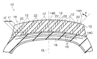
以下、本発明の実施の形態を図面に基づき説明する。本実施の形態に係る空気入りタイヤ10は、図1において、第1ゴム層12及び該第1ゴム層12より弾性率の小さい第2ゴム層22がトレッド踏面14Bの法線14Aに対して夫々傾斜しかつ互い違いにタイヤ幅方向に重なって配置されてなるトレッド14を有しており、トレッド14のタイヤ中心側には、ベルト層16、カーカス18が配置されている。
Hereinafter, embodiments of the present invention will be described with reference to the drawings. In the
第1ゴム層12のタイヤ幅方向における厚さt1は、第2ゴム層22のタイヤ幅方向における厚さt2以上である。このため、車輌の駆動力及び操舵力が路面に対して適切に伝達されるので、操縦安定性が高い。
The thickness t1 of the
なお、第1ゴム層12の厚さt1は、第2ゴム層22の厚さt2に対して2倍以上であることが好ましい。また、第2ゴム層22のtanδは0.150以下であることが望ましい。
Note that the thickness t1 of the
第1ゴム層12の弾性率は、7乃至17kgf/mm2であり、第2ゴム層22の弾性率は、3乃至5kgf/mm2である。
The elastic modulus of the
第1ゴム層12及び第2ゴム層22の傾斜角度θは、各々のタイヤ幅方向位置におけるトレッド踏面14Bの法線14Aに対して、夫々30乃至60°である。
The inclination angles θ of the
このような傾斜角度の設定により、トレッド踏面14Bとベルト層16との間の垂直方向において、適度な量の第1ゴム層12及び第2ゴム層22の層が生成されているので、駆動力及び操舵力を路面に適切に伝達でき、かつ低発熱により転がり抵抗を低く抑えることができる。
(作用)
具体的には、第1ゴム層12は、路面(図示せず)との接触によりトレッド14に発生する力を支持することができる。また、第1ゴム層12は、タイヤ幅方向に対して傾斜しているため、コーナリング時に該タイヤ幅方向に生じるせん断力に対する剛性が高く、操縦安定性の向上に大きな役割を果たす。
By setting such an inclination angle, an appropriate amount of the
(Function)
Specifically, the
第2ゴム層22は、路面との接触によるトレッド14の発熱を抑えて転がり抵抗を低減する役割を果たす。
The
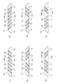
第1ゴム層12及び第2ゴム層22の配置例としては、例えば図2に示すものがある。図2(a)〜(f)に示す各トレッド14においては、左側が車輌外側であり、右側が車輌内側(左車輪に使用した状態)である。従って、右車輪に使用する場合には、第2ゴム層22の傾斜方向は夫々対称となる。
An example of the arrangement of the
具体的には、図2(a)のトレッド14を有する空気入りタイヤを、車輌の左車輪及び右車輪に取り付けたときには、第2ゴム層22が、左車輪において右上がりで、右車輪において左上がりとなる(図2(a)を左車輪、図2(b)を右車輪と見た場合に相当する)。
Specifically, when the pneumatic tire having the
図2(b)のトレッド14を有する空気入りタイヤを、車輌の左車輪及び右車輪に取り付けたときには、第2ゴム層22が、左車輪において左上がりで、右車輪において右上がりとなる。
When the pneumatic tire having the
図2(c)のトレッド14を有する空気入りタイヤを、車輌の左車輪及び右車輪に取りつけたときには、左右の車輪に係るトレッド14において、左半分の第2ゴム層22は右上がりで、右半分の第2ゴム層22は左上がりとなる。
When the pneumatic tire having the
図2(d)のトレッド14を有する空気入りタイヤを、車輌の左車輪及び右車輪に取りつけたときには、左右の車輪に係るトレッド14において、左半分の第2ゴム層22は左上がりで、右半分の第2ゴム層22は右上がりとなる。
When the pneumatic tire having the
図2(e)のトレッド14を有する空気入りタイヤを、車輌の左車輪及び右車輪に取りつけたときには、左側の車輪に係るトレッド14において、例えば6層ある第2ゴム層22のうち、左から4層目までの第2ゴム層22は右上がりで、残りの2層の第2ゴム層22は左上がりとなり、右側の車輪に係るトレッド14において、左から2層目までの第2ゴム層22は右上がりで、残りの4層の第2ゴム層22は左上がりとなる。
When the pneumatic tire having the
そして、図2(f)のトレッド14を有する空気入りタイヤを、車輌の左車輪及び右車輪に取りつけたときには、左側の車輪に係るトレッド14において、例えば6層ある第2ゴム層22のうち、左から4層目までの第2ゴム層22は左上がりで、残りの2層の第2ゴム層22は右上がりとなり、右側の車輪に係るトレッド14において、左から2層目までの第2ゴム層22は左上がりで、残りの4層の第2ゴム層22は右上がりとなる。
And when the pneumatic tire which has the
図2(a)〜(b)は、トレッドパターンが対称形となっているタイヤに有効で、図2(e)及び(f)は、トレッドパターンが非対称形となっているタイヤに有効である。 2 (a) to 2 (b) are effective for a tire having a symmetrical tread pattern, and FIGS. 2 (e) and 2 (f) are effective for a tire having an asymmetrical tread pattern. .
なお、図2において、第2ゴム層22は、断面長方形であり、その角部がトレッド14の内周側界面14C及びトレッド踏面14Bに夫々位置するように示しているが、これに限られるものではなく、図1に示すように、トレッド14の内周側界面14C及びトレッド踏面14Bに夫々面状に露出している方が望ましい。初めから露出していないと、ある程度トレッド14が摩耗したところで第2ゴム層22が露出して、その時点からタイヤ特性が変化するおそれがあるからである。第2ゴム層22が初めから露出していれば、トレッド14が摩耗しても、第2ゴム層22の露出状態は変化せず、タイヤ特性の変化もないからである。
(試験例)
トレッドを構成する第1ゴム層及び第2ゴム層の各々の弾性率を、表1に示す値に設定した従来例、比較例1、比較例2及び本発明に係る空気入りタイヤについて、操縦性及び転がり抵抗の試験を行った。
In FIG. 2, the
(Test example)
About the conventional example which set each elastic modulus of the 1st rubber layer which comprises a tread, and the 2nd rubber layer to the value shown in Table 1, comparative example 1, comparative example 2, and the pneumatic tire concerning the present invention, maneuverability The rolling resistance was tested.
従来例における第1ゴム層及び第2ゴム層は、タイヤ幅方向と平行に2層重ねられており、比較例1、比較例2及び本発明における第1ゴム層及び第2ゴム層は、傾斜状態で層状に重ねられている。 The first rubber layer and the second rubber layer in the conventional example are stacked in two layers parallel to the tire width direction, and the first rubber layer and the second rubber layer in the comparative example 1, the comparative example 2 and the present invention are inclined. The layers are stacked in a state.
タイヤサイズはPSR 205/55R16、内圧は220kPa、荷重は3.80kN、リムは7JJである。 The tire size is PSR 205 / 55R16, the internal pressure is 220 kPa, the load is 3.80 kN, and the rim is 7JJ.
操縦性の試験は、テストコースで実車を用いて行い、前席に1名(ドライバー)が乗車してそのフィーリングにより評価した。満点は10点であり、数値が大きいほど良好なフィーリングが得られたことを示している。 The maneuverability test was conducted using a real vehicle on the test course, and one person (driver) got on the front seat and evaluated the feeling. The full score is 10 points, and the larger the value, the better the feeling was obtained.
転がり抵抗の試験は、転がり抵抗試験機を用いて、惰行法により行い、速度80km/hで30分走行後惰行させて、その減速度から求めた転がり抵抗により評価し、従来例を100とした指数で示している。数値が大きいほど良好な結果である。 The rolling resistance test was performed by a coasting method using a rolling resistance tester, coasted after traveling for 30 minutes at a speed of 80 km / h, and evaluated based on the rolling resistance obtained from the deceleration. It is shown as an index. The larger the value, the better the result.
この試験例によれば、比較例1を従来例と比較してみると、操縦性は向上しているものの、転がり抵抗は悪化している。これは、第2ゴム層の弾性率が5kgf/mm2を超えているため、転がり抵抗が増加したものと考えられる。 According to this test example, when the comparative example 1 is compared with the conventional example, although the maneuverability is improved, the rolling resistance is deteriorated. This is considered that the rolling resistance increased because the elastic modulus of the second rubber layer exceeded 5 kgf / mm 2 .
次に、比較例2を従来例と比較してみると、転がり抵抗は変わらないが、操縦性が低下している。これは、第1ゴム層の弾性率が7kgf/mm2に満たないためであると考えられる。 Next, when the comparative example 2 is compared with the conventional example, the rolling resistance is not changed, but the maneuverability is lowered. This is considered to be because the elastic modulus of the first rubber layer is less than 7 kgf / mm 2 .
そして本発明を従来例と比較してみると、転がり抵抗はそのままでありながら、操縦性が向上しており、背反する性能が両立していることがわかる。これは、第1ゴム層及び第2ゴム層の弾性率が適切で、かつ傾斜状態で層状に重ねられているためである。 When the present invention is compared with the conventional example, it can be seen that while the rolling resistance remains the same, the maneuverability is improved and the contradicting performance is compatible. This is because the first rubber layer and the second rubber layer have appropriate elastic moduli and are layered in an inclined state.

10 空気入りタイヤ
12 第1ゴム層
14 トレッド
14A 法線
14B トレッド踏面
22 第2ゴム層
t1 第1ゴム層のタイヤ幅方向における厚さ
t2 第2ゴム層のタイヤ幅方向における厚さ
θ 傾斜角度
10
Claims (4)
前記第2ゴム層の弾性率は、3乃至5kgf/mm2であること、
を特徴とする請求項1又は請求項2に記載の空気入りタイヤ。 The elastic modulus of the first rubber layer is 7 to 17 kgf / mm 2 ,
The elastic modulus of the second rubber layer is 3 to 5 kgf / mm 2 ;
The pneumatic tire according to claim 1 or 2, characterized in that.
Priority Applications (1)
| Application Number | Priority Date | Filing Date | Title |
|---|---|---|---|
| JP2004364643A JP2006168564A (en) | 2004-12-16 | 2004-12-16 | Pneumatic tire |
Applications Claiming Priority (1)
| Application Number | Priority Date | Filing Date | Title |
|---|---|---|---|
| JP2004364643A JP2006168564A (en) | 2004-12-16 | 2004-12-16 | Pneumatic tire |
Publications (1)
| Publication Number | Publication Date |
|---|---|
| JP2006168564A true JP2006168564A (en) | 2006-06-29 |
Family
ID=36669761
Family Applications (1)
| Application Number | Title | Priority Date | Filing Date |
|---|---|---|---|
| JP2004364643A Pending JP2006168564A (en) | 2004-12-16 | 2004-12-16 | Pneumatic tire |
Country Status (1)
| Country | Link |
|---|---|
| JP (1) | JP2006168564A (en) |
Cited By (8)
| Publication number | Priority date | Publication date | Assignee | Title |
|---|---|---|---|---|
| JP2008024222A (en) * | 2006-07-24 | 2008-02-07 | Yokohama Rubber Co Ltd:The | Pneumatic tire |
| CN102649387A (en) * | 2011-02-28 | 2012-08-29 | 住友橡胶工业株式会社 | Radial tire for use in two-wheeled vehicle |
| US20180170112A1 (en) * | 2016-12-21 | 2018-06-21 | Toyo Tire & Rubber Co., Ltd. | Tire |
| US20180186192A1 (en) * | 2017-01-05 | 2018-07-05 | Toyo Tire & Rubber Co., Ltd. | Tire |
| CN108472998A (en) * | 2015-12-22 | 2018-08-31 | 米其林集团总公司 | Composite materials consisting of directional stacked hard-soft mixtures for mechanical coupling in the preparation of tire treads |
| CN111331889A (en) * | 2018-12-19 | 2020-06-26 | 固特异轮胎和橡胶公司 | Composite tread having a target stiffness gradient and method of manufacture |
| EP4292835A1 (en) * | 2022-06-17 | 2023-12-20 | Continental Reifen Deutschland GmbH | Vehicle tyre with directional stiffness |
| US11993110B2 (en) | 2018-12-19 | 2024-05-28 | The Goodyear Tire & Rubber Company | Reinforced tread and method of forming |
-
2004
- 2004-12-16 JP JP2004364643A patent/JP2006168564A/en active Pending
Cited By (15)
| Publication number | Priority date | Publication date | Assignee | Title |
|---|---|---|---|---|
| JP2008024222A (en) * | 2006-07-24 | 2008-02-07 | Yokohama Rubber Co Ltd:The | Pneumatic tire |
| CN102649387A (en) * | 2011-02-28 | 2012-08-29 | 住友橡胶工业株式会社 | Radial tire for use in two-wheeled vehicle |
| US20120216934A1 (en) * | 2011-02-28 | 2012-08-30 | Kengo Hara | Radial tire for use in two-wheeled vehicle |
| JP2012176707A (en) * | 2011-02-28 | 2012-09-13 | Sumitomo Rubber Ind Ltd | Radial tire for use in two-wheeled vehicle |
| CN108472998A (en) * | 2015-12-22 | 2018-08-31 | 米其林集团总公司 | Composite materials consisting of directional stacked hard-soft mixtures for mechanical coupling in the preparation of tire treads |
| US20180170112A1 (en) * | 2016-12-21 | 2018-06-21 | Toyo Tire & Rubber Co., Ltd. | Tire |
| US10688829B2 (en) | 2016-12-21 | 2020-06-23 | Toyo Tire Corporation | Tire |
| US20180186192A1 (en) * | 2017-01-05 | 2018-07-05 | Toyo Tire & Rubber Co., Ltd. | Tire |
| US10780742B2 (en) * | 2017-01-05 | 2020-09-22 | Toyo Tire Corporation | Tire |
| CN111331889A (en) * | 2018-12-19 | 2020-06-26 | 固特异轮胎和橡胶公司 | Composite tread having a target stiffness gradient and method of manufacture |
| US11541691B2 (en) * | 2018-12-19 | 2023-01-03 | The Goodyear Tire & Rubber Company | Composite tread with targeted stiffness gradient and method of making |
| US11993110B2 (en) | 2018-12-19 | 2024-05-28 | The Goodyear Tire & Rubber Company | Reinforced tread and method of forming |
| US12202221B2 (en) | 2018-12-19 | 2025-01-21 | The Goodyear Tire & Rubber Company | Composite tread with targeted stiffness gradient and method of making |
| US12441072B2 (en) | 2018-12-19 | 2025-10-14 | The Goodyear Tire & Rubber Company | Reinforced tread and method of forming |
| EP4292835A1 (en) * | 2022-06-17 | 2023-12-20 | Continental Reifen Deutschland GmbH | Vehicle tyre with directional stiffness |
Similar Documents
| Publication | Publication Date | Title |
|---|---|---|
| JP4369734B2 (en) | Pneumatic tire | |
| JP4328371B2 (en) | Pneumatic tires for motorcycles | |
| JP4527180B1 (en) | Pneumatic tire | |
| JP6488543B2 (en) | Pneumatic tire | |
| JP5030753B2 (en) | Pneumatic tire | |
| JP2014162340A (en) | Pneumatic tire | |
| EP0870630B1 (en) | Pneumatic tire | |
| JP2010006107A (en) | Pneumatic tire | |
| JP2006321287A (en) | Pneumatic radial tire for motorcycle | |
| CN101678721A (en) | Pneumatic tire for motorcycle | |
| JP2006168564A (en) | Pneumatic tire | |
| JP2007015596A (en) | Tire for passenger car | |
| JP5359322B2 (en) | Pneumatic tire unit | |
| JP2009269421A (en) | Pneumatic tire | |
| JP4910782B2 (en) | Pneumatic tire | |
| JP2006192929A (en) | Pneumatic tire | |
| JP4473689B2 (en) | Pneumatic tire | |
| JP5103081B2 (en) | Pneumatic tires for motorcycles | |
| JP2009051350A (en) | Pneumatic tire for motorcycle | |
| JPH07237407A (en) | Tires for all-terrain vehicles | |
| JPWO2009011344A1 (en) | Pneumatic tire | |
| JP2009126394A (en) | Pneumatic tire for motorcycle | |
| JP2009056952A (en) | Pneumatic tire | |
| JP4656989B2 (en) | Pneumatic tire | |
| JP2011068210A (en) | Pneumatic tire |