EP2491906B1 - Method and device for manufacturing composite of continuous sheets for absorptive article - Google Patents
Method and device for manufacturing composite of continuous sheets for absorptive article Download PDFInfo
- Publication number
- EP2491906B1 EP2491906B1 EP10824803.0A EP10824803A EP2491906B1 EP 2491906 B1 EP2491906 B1 EP 2491906B1 EP 10824803 A EP10824803 A EP 10824803A EP 2491906 B1 EP2491906 B1 EP 2491906B1
- Authority
- EP
- European Patent Office
- Prior art keywords
- continuous sheet
- peripheral surface
- sheet
- air intake
- leading end
- Prior art date
- Legal status (The legal status is an assumption and is not a legal conclusion. Google has not performed a legal analysis and makes no representation as to the accuracy of the status listed.)
- Not-in-force
Links
Images


Classifications
-
- B—PERFORMING OPERATIONS; TRANSPORTING
- B65—CONVEYING; PACKING; STORING; HANDLING THIN OR FILAMENTARY MATERIAL
- B65H—HANDLING THIN OR FILAMENTARY MATERIAL, e.g. SHEETS, WEBS, CABLES
- B65H35/00—Delivering articles from cutting or line-perforating machines; Article or web delivery apparatus incorporating cutting or line-perforating devices, e.g. adhesive tape dispensers
- B65H35/04—Delivering articles from cutting or line-perforating machines; Article or web delivery apparatus incorporating cutting or line-perforating devices, e.g. adhesive tape dispensers from or with transverse cutters or perforators
- B65H35/08—Delivering articles from cutting or line-perforating machines; Article or web delivery apparatus incorporating cutting or line-perforating devices, e.g. adhesive tape dispensers from or with transverse cutters or perforators from or with revolving, e.g. cylinder, cutters or perforators
-
- A—HUMAN NECESSITIES
- A61—MEDICAL OR VETERINARY SCIENCE; HYGIENE
- A61F—FILTERS IMPLANTABLE INTO BLOOD VESSELS; PROSTHESES; DEVICES PROVIDING PATENCY TO, OR PREVENTING COLLAPSING OF, TUBULAR STRUCTURES OF THE BODY, e.g. STENTS; ORTHOPAEDIC, NURSING OR CONTRACEPTIVE DEVICES; FOMENTATION; TREATMENT OR PROTECTION OF EYES OR EARS; BANDAGES, DRESSINGS OR ABSORBENT PADS; FIRST-AID KITS
- A61F13/00—Bandages or dressings; Absorbent pads
- A61F13/15—Absorbent pads, e.g. sanitary towels, swabs or tampons for external or internal application to the body; Supporting or fastening means therefor; Tampon applicators
- A61F13/15577—Apparatus or processes for manufacturing
- A61F13/15707—Mechanical treatment, e.g. notching, twisting, compressing, shaping
- A61F13/15723—Partitioning batts; Cutting
-
- A—HUMAN NECESSITIES
- A61—MEDICAL OR VETERINARY SCIENCE; HYGIENE
- A61F—FILTERS IMPLANTABLE INTO BLOOD VESSELS; PROSTHESES; DEVICES PROVIDING PATENCY TO, OR PREVENTING COLLAPSING OF, TUBULAR STRUCTURES OF THE BODY, e.g. STENTS; ORTHOPAEDIC, NURSING OR CONTRACEPTIVE DEVICES; FOMENTATION; TREATMENT OR PROTECTION OF EYES OR EARS; BANDAGES, DRESSINGS OR ABSORBENT PADS; FIRST-AID KITS
- A61F13/00—Bandages or dressings; Absorbent pads
- A61F13/15—Absorbent pads, e.g. sanitary towels, swabs or tampons for external or internal application to the body; Supporting or fastening means therefor; Tampon applicators
- A61F13/15577—Apparatus or processes for manufacturing
- A61F13/15764—Transferring, feeding or handling devices; Drives
-
- B—PERFORMING OPERATIONS; TRANSPORTING
- B65—CONVEYING; PACKING; STORING; HANDLING THIN OR FILAMENTARY MATERIAL
- B65H—HANDLING THIN OR FILAMENTARY MATERIAL, e.g. SHEETS, WEBS, CABLES
- B65H37/00—Article or web delivery apparatus incorporating devices for performing specified auxiliary operations
- B65H37/04—Article or web delivery apparatus incorporating devices for performing specified auxiliary operations for securing together articles or webs, e.g. by adhesive, stitching or stapling
-
- B—PERFORMING OPERATIONS; TRANSPORTING
- B65—CONVEYING; PACKING; STORING; HANDLING THIN OR FILAMENTARY MATERIAL
- B65H—HANDLING THIN OR FILAMENTARY MATERIAL, e.g. SHEETS, WEBS, CABLES
- B65H39/00—Associating, collating, or gathering articles or webs
- B65H39/14—Associating sheets with webs
-
- B—PERFORMING OPERATIONS; TRANSPORTING
- B65—CONVEYING; PACKING; STORING; HANDLING THIN OR FILAMENTARY MATERIAL
- B65H—HANDLING THIN OR FILAMENTARY MATERIAL, e.g. SHEETS, WEBS, CABLES
- B65H2301/00—Handling processes for sheets or webs
- B65H2301/10—Selective handling processes
-
- B—PERFORMING OPERATIONS; TRANSPORTING
- B65—CONVEYING; PACKING; STORING; HANDLING THIN OR FILAMENTARY MATERIAL
- B65H—HANDLING THIN OR FILAMENTARY MATERIAL, e.g. SHEETS, WEBS, CABLES
- B65H2511/00—Dimensions; Position; Numbers; Identification; Occurrences
- B65H2511/10—Size; Dimensions
-
- B—PERFORMING OPERATIONS; TRANSPORTING
- B65—CONVEYING; PACKING; STORING; HANDLING THIN OR FILAMENTARY MATERIAL
- B65H—HANDLING THIN OR FILAMENTARY MATERIAL, e.g. SHEETS, WEBS, CABLES
- B65H2513/00—Dynamic entities; Timing aspects
- B65H2513/10—Speed
-
- B—PERFORMING OPERATIONS; TRANSPORTING
- B65—CONVEYING; PACKING; STORING; HANDLING THIN OR FILAMENTARY MATERIAL
- B65H—HANDLING THIN OR FILAMENTARY MATERIAL, e.g. SHEETS, WEBS, CABLES
- B65H2801/00—Application field
- B65H2801/57—Diaper manufacture
-
- Y—GENERAL TAGGING OF NEW TECHNOLOGICAL DEVELOPMENTS; GENERAL TAGGING OF CROSS-SECTIONAL TECHNOLOGIES SPANNING OVER SEVERAL SECTIONS OF THE IPC; TECHNICAL SUBJECTS COVERED BY FORMER USPC CROSS-REFERENCE ART COLLECTIONS [XRACs] AND DIGESTS
- Y10—TECHNICAL SUBJECTS COVERED BY FORMER USPC
- Y10T—TECHNICAL SUBJECTS COVERED BY FORMER US CLASSIFICATION
- Y10T156/00—Adhesive bonding and miscellaneous chemical manufacture
- Y10T156/10—Methods of surface bonding and/or assembly therefor
- Y10T156/1052—Methods of surface bonding and/or assembly therefor with cutting, punching, tearing or severing
- Y10T156/1062—Prior to assembly
Definitions
- the present invention relates to a method and an apparatus for manufacturing a composite of a continuous sheet for an absorbent article such as a disposable diaper.
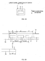
- a continuous film 101 is divided to produce single-cut films 103 having a predetermined length L103, and each of the produced single-cut films 103, 103...is adhered to a continuous sheet 105 such as a nonwoven fabric in a continuous direction thereof at a predetermined adhesion pitch P103.
- PTL 1 discloses a method using an anvil roll 111 that is driven to rotate in a circumferential direction Dc, a cutter roll 121 that is disposed facing the anvil roll 111 and rotates in synchronization with the anvil roll, and a transfer roll 131 disposed on a downstream side of the cutter roll 121 in the circumferential direction Dc.
- the continuous film 101 is supplied at a speed V101 to a peripheral surface 111a of the anvil roll 111 rotating at a predetermined peripheral speed V111, the speed being slower than the peripheral speed V111, and a part 101e on a leading end of the continuous film 101 is held on the peripheral surface 111a in a face contact state while sliding by a suction section of the peripheral surface acting thereto.
- the continuous film 101 is divided and the part 101e on the leading end is cut and separated by a blade 123 of the cutter roll 121 and the cutter receiving part 113, and thereby the single-cut film 103 is produced.
- the produced single-cut film 103 is transported in the circumferential direction Dc at the peripheral speed V111 of the anvil roll 111 while being held by the suction section of the peripheral surface 111a of the anvil roll 111.
- the single-cut film 103 passes a position that faces the transfer roll 131 in a transport path in the circumferential direction Dc, the single-cut film 103 is adhered to the continuous sheet 105 transported on the transfer roll 131.
- a transport speed V105 of the continuous sheet 105 and the peripheral speed V111 of the anvil roll 111 are both set as the same speed.
- the size of a product is generally changed in a production line. For example, in a case the size is changed from small to large, the length L103 of the single-cut film 103 and the adhesion pitch P103 are changed to become longer.
- change in the former length L103 of the single-cut film 103 can be easily met by increase-decrease adjustment of the supply speed V101 of the continuous film 101 with respect to the peripheral speed V111 of the anvil roll 111.
- the supply speed V101 should be increased in a case of elongating the length L103 of the single-cut film 103, and in contrast, the supply speed V101 should be decreased in a case of shortening the length L103.
- the latter adhesion pitch P103 cannot be easily changed as in the case mentioned above. That is, when changing the adhesion pitch P103 under a constraint that "the peripheral speed V111 of the anvil roll 111 and the transport speed V105 of the continuous sheet 105 are both the same" as in PTL 1, the anvil roll 111 needs to be changed to that having a roll diameter that corresponds to such adhesion pitch P103. This is because, the adhesion pitch P103 is uniquely determined by a disposition pitch P113 of the cutter receiving part 113 of the anvil roll 111 in the circumferential direction Dc since the peripheral speed V111 of the anvil roll 111 and the transport speed V105 of the continuous sheet 105 are both the same.
- the present invention was made in view of the foregoing issue, and it is an advantage thereof to provide a method and an apparatus for manufacturing a composite of a continuous sheet for an absorbent article that can change the product size without any roll exchange.
- a main aspect of the invention for solving the foregoing issue is method of manufacturing a composite of a continuous sheet for an absorbent article, dividing and producing from a first continuous sheet single-cut sheets of a predetermined length, and adhering the single-cut sheets to a second continuous sheet in a continuous direction thereof at a predetermined adhesion pitch, including:
- an apparatus for manufacturing a composite of a continuous sheet for an absorbent article dividing and producing from a first continuous sheet single-cut sheets of a predetermined length, and adhering the single-cut sheets to a second continuous sheet in a continuous direction thereof at a predetermined adhesion pitch, comprising:
- the product size can be changed without any roll exchange when manufacturing a composite of a continuous sheet for an absorbent article.
- a method of manufacturing a composite of a continuous sheet for an absorbent article, dividing and producing from a first continuous sheet single-cut sheets of a predetermined length, and adhering the single-cut sheets to a second continuous sheet in a continuous direction thereof at a predetermined adhesion pitch including:
- a change of product size can be easily managed. That is, in a case of changing a length of the single-cut film along with changing the product size, the first speed of the first continuous sheet should be relatively-changed with respect to the peripheral speed of the roll. Also, the adhesion pitch of the single-cut film can be changed by at least selecting either of the continuous sheets transported at the second speed or the continuous sheet transported at the third speed as the second continuous sheet. Thus, the product size can be changed without any roll exchange.
- the continuous sheet transported at the second speed is selected as the second continuous sheet in the selecting, in the adhering, a leading end in the peripheral direction of the single-cut sheet is adhered to the second continuous sheet, and thereafter, the single-cut sheet is pulled by the second continuous sheet via the leading end, and while a part of the single-cut sheet held on the peripheral surface slides relatively with respect to the peripheral surface in a travelling direction, the part is gradually peeled off from the peripheral surface to be overlapped and adhered onto the second continuous sheet.
- the single-cut sheet moves together with the peripheral surface of the roll at the peripheral speed before adhesion of the leading end of the single-cut sheet to the second continuous sheet, however, after the adhesion of the leading end to the second continuous sheet, the single-cut sheet can move together with the second continuous sheet at the second speed as the transport speed of the second continuous sheet by sliding relatively with respect to the peripheral surface.
- unreasonable load caused by relative speed difference between the peripheral speed of the peripheral surface and the second speed of the second continuous sheet is prevented from acting on the single-cut sheet when being handed over between the two. And as a result, generation of wrinkles on the single-cut sheet when being adhered to the second continuous sheet is prevented.
- the single-cut sheet moves together with the peripheral surface at the peripheral speed until the leading end part of the single-cut sheet is adhered to the second continuous sheet, and the single-cut sheet moves together with the second continuous sheet at the second speed while sliding relatively with respect to the peripheral surface in the travelling direction after the leading end part is adhered to the second continuous sheet.
- the single-cut sheet can be smoothly handed over from the peripheral surface to the second continuous sheet.
- the peripheral surface includes a leading end holding area that holds the leading end, and a rear part holding area that holds a part rear of the leading end in the peripheral direction, and a holding force per unit area for holding the single-cut sheet on the peripheral surface is smaller in the rear part holding area than in the leading end holding area.
- the rear part can relatively slide smoothly with respect to the peripheral surface that should be performed after adhesion of the leading end to the second continuous sheet.
- the leading end can be effectively prevented from being peeled that may be caused by air resistance or the like in a case where the single-cut sheet being held on the peripheral surface is transported at the peripheral speed. As a result, adhesion deficiency of the single-cut sheet to the second continuous sheet can be prevented.
- the peripheral surface includes the leading end holding area that holds the leading end part and a remaining area that is other than the leading end part holding area, and the leading end holding area includes a protruded part protruding outward in a radial direction of the roll beyond the remaining area.
- the remaining area is relatively distant from the second continuous sheet than the end holding area by an amount of at least the length of the protruded part.
- the peripheral surface includes a width direction that is perpendicular to the peripheral direction, a plurality of air intake holes are formed on the peripheral surface and the single-cut sheet is attracted and held on the peripheral surface by an air intake through the air intake holes, and a groove part is formed on the peripheral surface to connect at least some of the air intake holes in a breathable manner, and a part of the groove part is positioned on an outer side of the single-cut sheet in the width direction.
- the air intake hole connected to the groove part takes in outside air from the part of the groove part with relatively small resistance, and firm adsorption that may be caused by vacuum when the air intake hole is blocked by the single-cut sheet can be avoided.
- the peripheral surface is prevented from holding the single-cut sheet firmly, and in the aforementioned "adhering", a peeling-off resistance when peeling off the single-cut sheet from the peripheral surface is reduced, and thereby the single-cut sheet can be handed over from the peripheral surface to the second continuous sheet smoothly.
- the peripheral surface includes the leading end holding area that holds the leading end, and the rear part holding area that holds the part rear of the leading end in the peripheral direction, and the groove part is connected to some of the air intake holes positioned in the rear part holding area in a breathable manner.
- the peripheral surface includes a width direction that is perpendicular to the peripheral direction, a plurality of air intake holes are formed on the peripheral surface and the single-cut sheet is attracted and held on the peripheral surface by the air intake through the air intake holes, at an inside of the roll, at least some of the air intake holes are in communication with each other through a communication path in a breathable manner, and some of the air intake holes in communication with each other through the communication path are positioned on an outer side of the single-cut sheet in the width direction.
- the peripheral surface includes the leading end holding area that holds the leading end, and the rear part holding area that holds the part rear of the leading end part in the peripheral direction, and the communication path is in communication with some of the air intake holes positioned in the rear part holding area in a breathable manner.
- the firm adsorption alike vacuuming of the single-cut sheet that may occur in the rear holding area is prevented effectively.
- the rear part of the single-cut sheet can relatively slide with respect to the rear holding area smoothly which should be performed after adhesion of the leading end to the second continuous sheet.
- the second continuous sheet has a higher air permeability than the single-cut sheet
- a transport path of the second continuous sheet is in a direction parallel to a tangent direction of the peripheral surface
- an air intake mechanism is provided to an adjacent position of the transport path closest to the peripheral surface to perform through the second continuous sheet an air intake in a direction that separates the single-cut sheet from the peripheral surface, and in the adhering, at a time each portions of the peripheral surface passes the adjacent position, a holding force of each of the portions that holds the single-cut sheet is reduced, and thereby a portion of the single-cut sheet that passes the adjacent position transfers gradually from the peripheral surface to the second continuous sheet.
- the suction force by the air intake of the air intake mechanism at the adjacent position can act on the single-cut sheet through the second continuous sheet based on the high air permeability of the second continuous sheet. And the holding force of each of the portions of the peripheral surface is weakened when passing the adjacent position. Thus, the single-cut sheet can be transferred from the peripheral surface to the second continuous sheet smoothly at the adjacent position.
- the air intake mechanism is a suction belt conveyor that transports the second continuous sheet
- the suction belt conveyor includes a belt having a plurality of air intake holes, the belt moving along the transport path while attracting the second continuous sheet by an air intake through the air intake holes, and in the adhering, a suction force by the air intake through the air intake holes of the belt acts, through the second continuous sheet, on a portion of the single-cut sheet that is transferred from the peripheral surface to the second continuous sheet.
- the single-cut sheet can be attracted to the belt through the second continuous sheet.
- the load that is needed for peeling off the single-cut sheet from the peripheral surface after adhering the leading end of the single-cut sheet to the second continuous sheet can be imposed on the belt 44.
- the load on the second continuous sheet is reduced, and generation of wrinkles on the second continuous sheet can be suppressed.
- the peripheral surface includes the leading end holding area that holds the leading end and the remaining area that is other than the leading end holding area, and a space between the remaining area and the belt is larger than a sum of a thickness of the single-cut sheet and a thickness of the second continuous sheet.
- the contact between the remaining area and the second continuous sheet can be reduced, and it is possible to inhibit scratch damage on the surface of the second continuous sheet that may be caused by the relative speed difference between the second continuous sheet and the remaining area.
- the peripheral surface of the roll includes the leading end holding area that holds the leading end, and a remaining area that is other than the leading end holding area
- the second continuous sheet has a higher air permeability than the single-cut sheet
- a transport path of the second continuous sheet is in a direction parallel to a tangent direction of the peripheral surface, in an adjacent position closest the peripheral surface of the transport path
- an air intake mechanism is provided to perform an air intake in a direction that separates the single-cut sheet from the peripheral surface through the second continuous sheet
- the air intake mechanism is a suction belt conveyor that transports the second continuous sheet
- the suction belt conveyor includes a belt having a plurality of air intake holes, the belt moving along the transport path while attracting the second continuous sheet to a peripheral surface thereof by the air intake through the air intake holes, and a protruded part is provided at a portion in the peripheral surface of the belt that should face the leading end holding area of the roll.
- the leading end in the case of adhering the leading end of the single-cut sheet to the second continuous sheet, the leading end is attracted toward the second continuous sheet by the air intake of the belt of the suction belt conveyor, and in addition to this, the second continuous sheet can be pressed against the leading end by the protrusion of the belt. As a result, adhesion strength between the leading end and the second continuous sheet can be increased.
- the third speed is same as the peripheral speed, in the selecting, in a case where the continuous sheet transported at the third speed is selected as the second continuous sheet, the second continuous sheet is transported toward the roll along a transport path that wraps around the peripheral surface at a predetermined wrapping angle, and in the adhering, the single-cut sheet adheres to the second continuous sheet while wrapping around at the wrapping angle.
- the transport speed of the second continuous sheet becomes the same speed as the peripheral speed of the peripheral surface, and the relative speed difference between the single-cut sheet held on the peripheral surface and the second continuous sheet is nearly nil.
- generation of wrinkles when adhering the single-cut sheet to the second continuous sheet is suppressed efficiently.
- an apparatus for manufacturing a composite of a continuous sheet for an absorbent article dividing and producing from a first continuous sheet single-cut sheets of a predetermined length, and adhering the single-cut sheets to a second continuous sheet in a continuous direction thereof at a predetermined adhesion pitch, including:
- an intermediate component 1a that becomes a basis of a back face sheet 1 of a disposable diaper is manufactured as an example of the composite of the continuous sheet.
- FIGS. 2A and 2B respectively show schematic planar views of the back face sheet 1 and the intermediate component 1a that becomes the basis of the back face sheet 1.
- the back face sheet 1 shown in FIG. 2A is a composite sheet 1 that includes an exterior sheet 5 forming an exterior of the diaper, an impermeable leak-proof film 3 that is adhered to a face in an inner side of the exterior sheet 5 (face on a side of a wearer's skin).
- an absorbent body that is not shown formed by molding a pulp fiber, a permeable surface sheet that is also not shown and the like are successively stacked and fixed, and become a basis of the diaper.
- a nonwoven fabric that includes a resin fiber as main material or the like can be given as an example of a material of the exterior sheet 5, and here, it is the nonwoven fabric.
- a resin film or the like can be given as an example of a material of the leak-proof film 3, and here, it is the resin film.
- the planar size of the leak-proof film 3 is smaller than the planar size of the exterior sheet 5. Also, air permeability of the leak-proof film 3 in the thickness direction (direction that penetrates the paper surface) is lower than air permeability of the exterior sheet 5 in the thickness direction.
- the intermediate component 1a that becomes the basis of the back face sheet 1 is a continuous body before being divided into back face sheets 1 at a product pitch P. That is, the intermediate component 1a is made by intermittently adhering a plurality of leak-proof films 3, 3... on the continuous sheet 5a of the nonwoven fabric as original cloth of the exterior sheet 5 in a continuing direction thereof at an adhesion pitch P3 having a same value as the product pitch P.
- the method of manufacturing the intermediate component 1a includes a process of dividing a continuous film 3a (corresponds to a first continuous sheet) as an original cloth of the leak-proof film 3 and thereby producing a single-cut film 3 (corresponds to a single-cut sheet) having a predetermined length of L3, and a process of adhering the produced single-cut film 3 as the leak-proof film 3 to the continuous sheet 5a (corresponds to a second continuous sheet) as an original cloth of the exterior sheet 5 in the continuing direction thereof at the above mentioned adhesion pitch of P3.
- the length L3 of the single-cut film 3 and the adhesion pitch P3 need to be changed for changing the product size.
- such requirements can be easily met without any exchanging of large-scale equipment and the like such as roll exchange and the like as explained below.
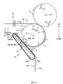
- FIG. 3 is a schematic side view of an apparatus 10 for manufacturing used in the method of manufacturing according to the present embodiment.
- a width direction of the continuous sheet 5a is referred to as the CD direction
- this CD direction is perpendicular to a transport direction (continuous direction) of the continuous sheet 5a, and points a direction that penetrates the paper surface in FIG. 3 .
- the apparatus 10 for manufacturing includes, (1) an anvil roll 11 that is driven to rotate about a rotational axis C11 pointing the CD direction at a predetermined peripheral speed V11 in a circumferential direction Dc, (2) a continuous film supply mechanism 21 that continuously supplies the continuous film 3a to a peripheral surface 11a of the anvil roll 11 at a supply speed V3a slower than the peripheral speed V11, (3) a cutter roll 31 that is disposed to face the anvil roll 11 at a predetermined position Q31 in the circumferential direction Dc and divides the continuous film 3a in cooperation with the anvil roll 11 and thereby produces the single-cut film 3, and (4) a continuous sheet transport mechanism 41 that continuously supplies the continuous sheet 5a toward the peripheral surface 11a of the anvil roll 11 while coinciding a transport direction thereof with a rotating direction of the anvil roll 11 for the purpose of adhering the single-cut film 3 held on the peripheral surface 11a of the anvil roll 11 to the continuous sheet 5a.
- the aforementioned affixation of the single-cut film 3 on the continuous sheet 5a is performed by adhesion. That is, before adhesion, an adhesive is pre-applied on at least either of the faces to be adhered to each other, which is the continuous sheet 5a or the single-cut film 3.
- a hot-melt adhesive is applied on a substantially entire surface of one side of the continuous film 3a by an adhesive applying system 81 right before supplying the continuous film 3a to the anvil roll 11.
- the anvil roll 11 (corresponds to roll) is a cylindrical body having a perfect-circular cross section. At the peripheral surface 11a thereof, a receiving part 12 is provided for receiving a flat blade 32 of the cutter roll 31 (corresponds to a cutter receiving part).
- the receiving parts 12 are disposed at an equal pitch P12 in the circumferential direction Dc, and in the illustrated example, are disposed at two locations in the circumferential direction Dc. In this way, a sheet of single-cut film 3 is divided and produced by a half-turn of the anvil roll 11.
- the peripheral surface 11a has a function of holding sheet-type material by wrapping it around thereto in a state of face contact, and in this way, the single-cut film 3 that is divided and produced by the cutter roll 31, and a leading end 3ae of the continuous film 3a before being divided into the single-cut film 3 is held on the peripheral surface 11a in a state of face contact.
- this holding function is achieved by a plurality of air intake holes 13 formed on the peripheral surface 11a (not shown in FIG. 3 ). That is, suction force acts on the peripheral surface 11a of the anvil roll 11 by an air intake through the air intake holes 13, and this suction force becomes the holding force for holding the single-cut film 3 or the leading end 3ae of the continuous film 3a described above.
- the continuous film supply mechanism 21 (corresponds to a first supply mechanism) has a pair of upper and lower pinch rolls 22a, 22b for example. And the pinch rolls 22a and 22b are driven to rotate while sandwiching the continuous film 3a therebetween, and supply the continuous film 3a to the peripheral surface 11a of the anvil roll 11 at the predetermined supply speed V3a.
- this supply speed V3a (corresponds to first speed) is set slower than the peripheral speed V11 of the anvil roll 11. Therefore, the leading end 3ae of the continuous film 3a is held on the peripheral surface 11a in a state of face contact while sliding in a direction to fall behind along the peripheral surface 11a of the anvil roll 11, until it is divided and separated from the continuous film 3a by the cutter roll 31. That is, the leading end 3ae of the continuous film 3a gradually moves toward a downstream side in the circumferential direction Dc while sliding on the peripheral surface 11a at the supply speed V3a. And as shown in FIG.
- the leading end 3ae moves as the single-cut film 3 at the speed V3 same as the peripheral speed V11 of the anvil roll 11 while being held together on the peripheral surface 11a of the anvil roll 11. In this way, a space is generated between the succeeding single-cut film 3 that is divided and produced subsequently. And when reaching a supply position Q5a of the continuous sheet 5a set downstream in the circumferential direction Dc, the single-cut film 3 is adhered to the continuous sheet 5a and moves integral with the continuous sheet 5a.
- the cutter roll 31 (corresponds to cutter) includes the roll 31 that is driven to rotate about a rotational axis C31 pointing the CD direction as a main body, and the flat blade 32 is provided on a peripheral surface 31a thereof.
- the cutter roll 31 is driven to rotate in synchronization with the anvil roll 11, and divides the leading end 3ae from the continuous film 3a in cooperation with the anvil roll 11 and thereby produces the single-cut film 3.
- the cutter roll 31 is driven to rotate so that the flat blade 32 of the cutter roll 31 faces the receiving part 12 of the anvil roll 11 every time the receiving part 12 of the anvil roll 11 that rotates in the circumferential direction Dc passes the position Q31 of the cutter roll 31, and in this way the cutter roll 31 cuts and separates the leading end 3ae from the continuous film 3a in cooperation with the anvil roll 11.
- a perimeter of the pitch circle of the flat blade 32 of the cutter roll 31 (path of an edge of the flat blade 32) and a perimeter of the pitch circle of the receiving part 12 of the anvil roll 11 (path of an edge of the receiving part 12) are set as a same value.
- numbers of the flat blade 32 and the receiving part 12 are set the same being two.
- the continuous sheet transport mechanism 41 (corresponds to second supply mechanism) includes, for example, a transport route RS for small size products for transporting a continuous sheet 5aS (5a) for small size products shown in a chain double-dashed line in FIG. 3 , and a transport route RL for large size products for transporting a continuous sheet 5aL (5a) for large size products shown in a solid line in the same FIG. 3 .
- the transport route RL for large size products can supply the continuous sheet 5aL toward the peripheral surface 11a of the anvil roll 11 by setting a predetermined position in the circumferential direction Dc as a supply position Q5aL (Q5a) for large size products.
- the transport route RS for small size products can supply the continuous sheet 5aS toward the peripheral surface 11a by setting a position in the upstream side of the supply position Q5aL for large size products in the circumferential direction Dc as a supply position Q5aS (Q5a) for small size products.
- the transport route RS for small size products and the transport route RL for large size products are selected and used alternatively according to the change in product size. Due to the cooperation of this alternative selection and change in the supply speed V3a of the continuous film 3a made by the continuous film supply mechanism 21, the product size changed is performed as described below.
- the continuous film supply mechanism 21 sets the supply speed V3a of the continuous film 3a to a slow speed V3aS for small size products.
- V3aS slow speed for small size products.
- supply amount of the continuous film 3a per half-turn of the anvil roll 11 decreases, and the leading end 3ae of the continuous film 3a is divided into a short length L3S for small size products by the cutter roll 31 or the like, and as a result, the short single-cut film 3 for small size products is produced and held on the peripheral surface 11a of the anvil roll 11.
- the transport route RS for small size products is selected at the continuous sheet transport mechanism 41.
- the continuous sheet 5aS having narrow width that corresponds to small size products corresponds to continuous sheet that is transported at a third speed
- the continuous sheet 5aS is transported at a transport speed V5aS that is adapted to transport small size products (corresponds to the third speed) and in the example, it is transported at a same speed as the peripheral speed V11 of the anvil roll 11.
- the short single-cut film 3 for small size products is adhered intermittently at an adhesion pitch P3S that is adapted to small size products and thereby the intermediate component 1a for small size products is manufactured.
- the continuous film supply mechanism 21 sets the supply speed V3a of the continuous film 3a to a speed V3aL faster than the supply speed V3aS for small size products. Thereby, supply amount of the continuous film 3a per half-turn of the anvil roll 11 increases, and the leading end 3ae of the continuous film 3a is divided into a long length L3L for large size products by the cutter roll 31 or the like, and as a result, the long single-cut film 3 for large size products is produced and held on the peripheral surface 11a of the anvil roll 11.
- the transport route RL for large size products is selected at the continuous sheet transport mechanism 41.
- the continuous sheet 5aL having broad width that corresponds to large size products (corresponds to continuous sheet that is transported in a second speed) is transported.
- the continuous sheet 5aL is transported at a transport speed V5aL (corresponds to the second speed) that is adapted to transport large size products and is faster than the transport speed V5aS that is adapted to transport small size products. That is, in the example of FIG. 3 , the continuous sheet 5aL is transported at the speed V5aL that is faster than the peripheral speed V11 of the anvil roll 11.
- long single-cut films 3 for large size products are adhered intermittently at a long adhesion pitch P3L that is adapted to large size products and thereby the intermediate component 1a for large size is manufactured.
- the transport route RS for small size products is set as a transport path in which the continuous sheet 5aS for small size products is wrapped around the peripheral surface 11a of the anvil roll 11 at a predetermined wrapping angle ⁇ .
- the single-cut film 3 held on the peripheral surface 11a of the anvil roll 11 passes this wrapping-around range Aw, the single-cut film 3 is transferred from the peripheral surface 11a to the continuous sheet 5aS and is adhered to the continuous sheet 5aS, however, at the time of this transfer, the peripheral speed V11 of the anvil roll 11 and the transport speed V5aS of the continuous sheet 5aS are set to the same speed as described before. Therefore, there is no fear of the single-cut film 3 or the continuous sheet 5aS getting wrinkled caused by a relative speed difference during this transfer.
- the peripheral speed V11 of the anvil roll 11 and the transport speed V5aL of the continuous sheet 5aL differ from each other.
- the relative speed difference is small, wrinkles may not be obvious due to elastic deformation of the continuous sheet 5aL or the single-cut film 3.
- the relative speed difference is large, there is a high possibility of the single-cut film 3 or the continuous sheet 5aL getting wrinkled because of the speed difference during the transfer of the single-cut film 3.
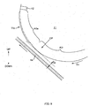
- a part RLP of the transport path is set along a direction parallel to a tangent direction of the peripheral surface 11a of the anvil roll 11.
- the transport path RLP is set as a route that most approaches the peripheral surface 11a at the supply position Q5aL in the circumferential direction Dc.
- the supply position Q5aL at which the closest approach is made in each of the transport route RL for large size products and the circumferential direction Dc is also referred to as "adjacent position CP".
- the leading end 3e that is a downstream end in the circumferential direction Dc of the single-cut film 3 is adhered to the continuous sheet 5aL.
- the transport speed V5aL of the continuous sheet 5aL is faster than the peripheral speed V11 of the anvil roll 11
- the single-cut film 3 is pulled by the continuous sheet 5aL via the leading end 3e, and thereby a part 3r of the single-cut film 3 that is held on the peripheral surface 11a slides relatively with respect to the peripheral surface 11a in a travelling direction. And while sliding, the part 3r is gradually peeled off from the peripheral surface 11a and is overlapped and adhered on the continuous sheet 5aL.
- the single-cut film 3 moves together with the peripheral surface 11a at the peripheral speed V11 of the peripheral surface 11a, however, after the adhesion of the leading end 3e as shown in FIG. 5 , the single-cut film 3 moves together with the continuous sheet 5aL at the transport speed V5aL of the continuous sheet 5aL by sliding relatively with respect to the peripheral surface 11a in the travelling direction.
- unreasonable pulling-load caused by relative speed difference between the continuous sheet 5aL and the peripheral face 11a acting on the single-cut film 3 is suppressed. And as a result, generation of wrinkles at the time of adhesion is prevented.
- ingenuities exercised on the anvil roll 11 described later also contribute largely to the relative sliding, and this will be described later.
- a suction belt conveyor 43 (corresponds to air intake mechanism) is used as a transport mechanism of the transport route RL for large size products, for the purpose of performing such hand over of the single-cut film 3 via the leading end part 3e.
- the conveyor 43 includes an endless belt 44 that travels in a predetermined orbit, and a plurality of air intake holes 45, 45... are formed on approximately the entire surface of a mounting face of the belt 44. And by the air intake through the air intake holes 45, 45... the continuous sheet 5aL is attracted to the mounting face.
- a part of the orbit is set along the direction parallel to the tangent direction of the peripheral surface 11a of the anvil roll 11.
- the part RLP of the transport path is set along the direction parallel to the tangent direction of the peripheral surface 11a of the anvil roll 11.
- the air intake through each of the air intake holes 45, 45... continues while each portions of the belt 44 passes the adjacent position CP in the transport path RLP.
- the air intake is performed through the continuous sheet 5aL having high air permeability in a direction that separates the single-cut film 3 from the peripheral surface 11a. And in this way, first, the leading end 3e of the single-cut film 3 is drawn toward the continuous sheet 5aL and adhered to the continuous sheet 5aL.
- each of the portions 3r on the rear side of the leading end 3e passes the adjacent position CP, however, also at that time, each of the portions 3r is drawn toward the continuous sheet 5aL successively by the air intake performed through the belt 44 and the continuous sheet 5aL having high air permeability, and is adhered to the continuous sheet 5aL.
- the continuous sheet 5aL has a higher air permeability than the single-cut film 3
- suction force caused by the air intake through the belt 44 wholly acts on the single-cut film 3 through the continuous sheet 5aL, to the portion of the single-cut film 3 that is transferred from the peripheral surface 11a to the continuous sheet 5aL.
- the single-cut film 3 is attracted to the belt 44 and thereby, a component of force needed for peeling off the single-cut film 3 from the peripheral surface 11a in the transport direction can be imposed on the belt 44.
- the load needed for the peeling-off that may be imposed on the continuous sheet 5aL mainly via the leading end 3e after adhering the leading end 3e can be imposed on the belt 44. And thus, the load on the continuous sheet 5aL is reduced and generation of wrinkles on the continuous sheet 5aL can be suppressed.
- the endless belt 44 can be configured so as to swing in a direction to separate from the anvil roll 11 by using either of the pair of pulleys 47a, 47b that form the orbit of the endless belt 44 as a fulcrum.
- the pulley 47a positioned on a downstream side can be configured so as to swing by using the pulley 47b positioned on an upstream side of the adjacent position CP in the transport route RL for large size products as the fulcrum.
- the endless belt 44 By configuring so that, in a case of the leading end 3e of the single-cut film 3 passing the adjacent position CP, the endless belt 44 approaches the anvil roll 11 to press the continuous sheet 5aL to the leading end 3e, and on the other hand, after the leading end 3e has passed the adjacent position CP, the endless belt 44 is moved so as to separate from the anvil roll 11 to a passing position that is spaced by a predetermined distance, the leading end part 3e can be firmly adhered to the continuous sheet 5aL.
- the anvil roll 11 includes the plurality of air intake holes 13, 13... on the smooth peripheral surface 11a thereof, and the single-cut film 3 is attracted to the peripheral surface 11a by the air intake through these air intake holes 13, 13....
- these air intake holes 13, 13... move in the circumferential direction Dc together with the peripheral surface 11a by rotation of the anvil roll 11.
- each of the air intake holes 13, 13... is configured to turn on/off the air intake movement according to each position along the circumferential direction Dc.
- FIG. 6 is an explanatory diagram of an example of areas in which the air intake movement is turned on/off in the circumferential direction Dc.
- inner configurations of the anvil roll 11 and the suction belt conveyor 43 are described.
- the air intake through the air intake holes 13 is turned on in an area from a position Q3a where the continuous film 3a is supplied to the peripheral surface 11a, through the position Q31 of the cutter roll 31, to the adjacent position CP that corresponds to a transfer position of the single-cut film 3.
- the air intake of the air intake holes 13 is turned off. Therefore, when each portions of the peripheral surface 11a passes the adjacent position CP in the circumferential direction Dc, the air intake of the air intake hole 13 of each of the portions stops.
- the part of the single-cut film 3 that has passed the adjacent position CP can smoothly transfer from the peripheral surface 11a to the continuous sheet 5aL successively.
- the air intake holes 13 returns to the supply position Q3a of the continuous film 3a by further moving in the circumferential direction Dc, the air intake through the air intake holes 13 turns on again and repeats the above mentioned movement.
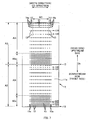
- FIG. 7 is an explanatory diagram of a disposition pattern of the air intake holes 13 on the peripheral surface 11a of the anvil roll 11, and it is a developed view of the peripheral surface 11a in the circumferential direction Dc.
- the peripheral surface 11a has two areas A3, A3 aligned in the circumferential direction Dc that attract and hold the single-cut film 3.
- Each of the areas A3, A3 can hold one sheet of single-cut film 3.
- each of the areas A3, A3 has a leading end holding area A3e and a rear part holding area A3r.
- the leading end holding area A3e is an area for attracting and holding the leading end 3e of the single-cut film 3, and is set for a predetermined area from a position nearest to the receiving part 12 on an upstream side as the start point to a further upstream side in the circumferential direction Dc.
- the rear part holding area A3r is set further upstream of the leading end holding area A3e in the circumferential direction Dc and attracts and holds the part 3r that is at the rear of the leading end 3e of the single-cut film 3.
- a disposition density of the air intake holes 13 (number of the air intake holes 13 disposed per unit area of the peripheral surface 11a) is lower in the rear part holding area A3r than in the leading end holding area A3e.
- a force for holding the single-cut film 3 per unit area is smaller in the rear part holding area A3r than in the leading end holding area A3e.
- the rear part 3r can relatively slide with respect to the peripheral surface 11a smoothly which should be performed after adhesion of the leading end 3e to the continuous sheet 5aL.
- the single-cut film 3 held on the peripheral surface 11a is integrally transported by the anvil roll 11 at the peripheral speed V11, there is fear of the leading end 3e of the single-cut film 3 being lifted by air resistance or the like.
- the leading end 3e is effectively prevented from being lifted. As a result, adhesion deficiency of the single-cut film 3 to the continuous sheet 5aL is prevented.
- a groove part 15 is formed on the peripheral surface 11a that connects at least some of the air intake holes 13, 13... in a breathable manner, and a part 15e of the groove part 15 is positioned outside the single-cut film 3 in the width direction (CD direction). Thereby outside air can be taken from the part 15e to the intake holes 13.
- a plurality of rows 13R are aligned and disposed in the circumferential direction Dc, and the row 13R consists of the plurality of air intake holes 13, 13 aligned in the CD direction.
- Each of the rows 13R of air intake holes includes a groove part 15 along the CD direction, and thereby the air intake holes 13, 13 that belong to the same row 13R of air intake holes are in communication with each other through the groove part 15 in a breathable manner.
- a width size W3 of the single-cut film 3 is shown, and positions of both end parts 15e, 15e of the groove part 15 are located outside the single-cut film 3 in the width direction respectively.
- the peripheral surface 11a is prevented from holding the single-cut film 3 firmly and as a result, the peripheral surface 11a can hand over the single-cut film 3 to the continuous sheet 5aL smoothly.
- the groove part 15 is effective especially to the row 13R of air intake holes positioned in the rear part holding area A3r. That is, it is preferable that the groove part 15 is connected to some of the air intake holes 13 positioned in the rear part holding area A3r in the breathable manner. In this way, the single-cut film 3 slides relatively with respect to the rear part holding area A3r smoothly that should be performed after adhering the leading end 3e of the single-cut film 3 to the continuous sheet 5aL. And as a result, generation of wrinkles on the single-cut film 3 can be suppressed more effectively.
- the groove part 15 is formed along the CD direction as in FIG. 7 .
- the carving pattern of the groove part 15 is not limited to this.
- each of the air intake holes 13, 13... aligned in a zigzag-form in the CD direction can be connected by a groove part 15 in a zigzag-line form.
- the firm attracting through the air intake hole 13 caused by the blockage can be prevented in a way as follows. That is, at least some of the air intake holes 13, 13... can be in communication with each other through a communication path 14 inside the anvil roll 11 in a breathable manner, and at the same time, some of the air intake holes 13, 13... in communication with each other through the communication path 14 can be positioned outside the single-cut film 3 in the CD direction.
- a communication path 14 that corresponds to the row 13R of air intake holes is formed inside the anvil roll 11 along the CD direction, and the air intake holes 13, 13... that belong to the same row 13R of air intake holes are in communication with each other through the corresponding communication path 14 in a breathable manner.
- positions of the air intake holes 13, 13 of each of the rows 13R of air intake holes at both ends in the CD direction are respectively located outside the single-cut film 3 in the width direction as shown in FIG. 7 . In such way, each of the air intake holes 13, 13...
- a valve can be provided in the communication path 14 for adjusting an air intake amount.
- such configuration for preventing the vacuum blockage of the communication path 14 or the like is preferably applied especially to the row 13R of air intake holes positioned in the rear part holding area A3r. That is, it is preferable that the communication path 14 is in communication with some of the air intake holes 13, 13... positioned in the rear part holding area A3r in a breathable manner. In this way, the single-cut film 3 slides relatively with respect to the rear part holding area A3r smoothly that should be performed after adhering the leading end part 3e of the single-cut film 3 to the continuous sheet 5aL.
- the leading end holding area A3e includes a protruded part 11p, and the protruded part 11p protrudes outward in a radial direction of the anvil roll 11 than the remaining area A3r besides the leading end holding area A3e on the peripheral surface 11a.
- an area having an increased diameter is set in a predetermined area that is from a position of the receiving part 12 to a further upstream side in the circumferential direction Dc (backward side) in the leading end holding area A3e.
- the amount of increased diameter 5 is, for example, from 0.2 mm to 1.0 mm in radius.
- the leading end 3e of the single-cut film 3 in the case of adhering the leading end 3e of the single-cut film 3 to the continuous sheet 5aL, the leading end 3e can be pressed against the continuous sheet 5aL by the protruded part 11p of the leading end holding area A3e. As a result, adhesion strength between the leading end part 3e and the continuous sheet 5aL can be increased.
- a space Ge between the protruded part 11p and the belt 44 is set so as to become smaller than the sum of a thickness of the single-cut film 3 and the thickness of the continuous sheet 5aL at the adjacent position CP in which the belt 44 of the suction belt conveyor 43 and the peripheral surface 11a of the anvil roll 11 make the closest approach to each other.
- each of the thicknesses can be measured as a distance that appears between a pair of indenters, for example a pair of indenters included in a thickness gage (trade name: PEACOK DIAL THICKNESS GAUGE No.11352), when sandwiching an entire surface of a square sample of 10cm x 10cm under pressure of 3g/cm 2 in the thickness direction.
- a thickness gage trade name: PEACOK DIAL THICKNESS GAUGE No.11352
- the remaining area A3r is relatively distant from the continuous sheet 5aL than the leading end holding area A3e at least for the protruded part 11p.
- contact between the continuous sheet 5aL and the peripheral surface 11a can be suppressed while increasing the pressing force applied to the leading end 3e.
- a space Gr between the belt 44 and the remaining area A3r of the peripheral surface 11a at the adjacent position CP is set so as to be larger than the sum of the thickness of the single-cut film 3 and the thickness of the continuous sheet 5aL. In this way, the contact between the remaining area A3r and the continuous sheet 5aL can be avoided and the above mentioned scratch damage on the continuous sheet 5aL can be surely suppressed.
- the protruded part 44p can be formed in a portion which should face the leading end part holding area A3e of the anvil roll 11 in an peripheral surface of the endless belt 44.
- the protruded part 44p is disposed at a predetermined disposition pitch in two positions as an example of the plurality of positions in an orbiting direction of the endless belt 44. This disposition pitch coincides with the adhesion pitch P3L of the single-cut film 3 of a large size.
- the air intake hole 45 is provided in the same way as in the other portion of the endless belt 44.
- the conveyor 43 of FIG. 10 is used to manufacture intermediate components 1a for large size products and is not necessarily needed to manufacture intermediate components 1a for small size products, however, should there be a case of using the conveyor 43 in manufacturing the intermediate component 1a for small size products, the conveyor 43 will need to be exchanged according to the change in product size from large to small. This is because, the disposition pitch of the protruded part 44p of the endless belt 44 is made to coincide with the adhesion pitch P3 of the single-cut film 3, and the adhesion pitch P3S for small size products and the adhesion pitch P3L for large size products differ from each other. However, the anvil roll 11 does not have to be exchanged in this configuration.
- the method using the air intake mechanism has been exemplified as a method for adhering to the continuous sheet 5aL the leading end 3e of the single-cut film 3 held on the peripheral surface 11a of the anvil roll 11. That is, the leading end 3e of the single-cut film 3 was attracted to the peripheral surface 11a of the anvil roll 11 and adhered to the continuous sheet 5aL by the suction belt conveyor 43 as the air intake mechanism.
- physical pressing can be adopted. More specifically, a hammer roll 51 shown in FIG. 11 can be used.
- the hammer roll 51 includes as a main body a roll member disposed in the adjacent position CP by facing the peripheral surface 11a of the anvil roll 11, and is driven to rotate about a rotational axis C51 pointing the CD direction.
- a convex part 51a projecting in a radial direction of the hammer roll 51 is included.
- the hammer roll 51 is driven to rotate so that the convex part 51a faces the peripheral surface 11a each time the leading end 3e of the single-cut film 3 held on the peripheral surface 11a of the anvil roll 11 passes the adjacent position CP. In this way, the continuous sheet 5aL is pressed against the leading end 3e of the single-cut film 3 by the convex part 51a and thereby, the leading end 3e is adhered firmly to the continuous sheet 5aL.
- the suction belt conveyor 43 can be used as the transport mechanism that forms the transport path RL of the continuous sheet 5aL.
- the transport route RL for large size products as mentioned above can be set, and for example, the transport route RL for large size products can be set to run across the continuous sheet 5aL between two pass line rolls 53, 54 as shown in FIG. 11 .
- the length L3 (L3S, L3L) of the single-cut film 3 in the circumferential direction Dc in FIG. 3 was not described in detail.
- the length L3 can be set longer than half the length of the disposition pitch P12 of the receiving part 12 on the peripheral surface 11a of the anvil roll 11 in the circumferential direction Dc, and shorter than the disposition pitch P12.
- the single-cut film 3 is attracted firmly to the peripheral surface 11a of the anvil roll 11 due to the relatively long length thereof, and thereby the single-cut film 3 becomes hard to peel off from the peripheral surface 11a.
- the ingenuities exercised on the anvil roll 11 mentioned before exert effects in such a case, and operational advantages thereof (such as preventing the sealed state associated with vacuuming of the air intake hole 13) can be enjoyed sufficiently.
- the leading end 3e of the single-cut film 3 transfers from the leading end holding area A3e to the continuous sheet 5aL by jumping, and in this way, is prevented from being effected by the relative speed difference between the peripheral surface 11a of the anvil roll 11 and the continuous sheet 5aL, and as a result, appearance of wrinkles on the leading end 3e of the single-cut film 3 can be suppressed further reliably.
- the change in size between two sizes such as small and large was mentioned as an example of the change in product size, however, there is no limitation to this, and the change in size between three sizes can be performed by adding medium size, and furthermore, other sizes such as XS and XL can be added too.
- the transport route RS of the continuous sheet 5aS for small size products that is an example of "the continuous sheet transported at the third speed"
- a path that wraps around the anvil roll 11 at the predetermined wrapping angle ⁇ was exemplified.
- the transport speed V5aS of the continuous sheet 5aS for small size products can be set freely within a range of speed faster than or equal to the peripheral speed V11 of the anvil roll 11 and speed slower than the transport speed V5aL.
- the suction through the air intake holes 13 on the peripheral surface 11a was exemplified as an example of a method of holding the single-cut film 3 or the like on the peripheral surface 11a of the anvil roll 11.
- the single-cut film 3 or the like is held in a slidable manner with respect to the peripheral surface 11a.
- the film was mentioned as an example of the single-cut sheet and the first continuous sheet.
- the nonwoven fabric or woven fabric or the like can be used.
- the nonwoven fabric was mentioned as an example of the second continuous sheet, however, there is no limitation to this as long as it is in a sheet-form, and woven fabric or film or the like can be used.
Description
- The present invention relates to a method and an apparatus for manufacturing a composite of a continuous sheet for an absorbent article such as a disposable diaper.
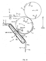
- In a manufacturing line of an absorbent article such as a disposable diaper or a sanitary napkin, as shown in
FIG. 1 , acontinuous film 101 is divided to produce single-cut films 103 having a predetermined length L103, and each of the produced single-cut films continuous sheet 105 such as a nonwoven fabric in a continuous direction thereof at a predetermined adhesion pitch P103. - As an example of this method,
PTL 1 discloses a method using an anvil roll 111 that is driven to rotate in a circumferential direction Dc, acutter roll 121 that is disposed facing the anvil roll 111 and rotates in synchronization with the anvil roll, and atransfer roll 131 disposed on a downstream side of thecutter roll 121 in the circumferential direction Dc. - To be specific, first, the
continuous film 101 is supplied at a speed V101 to aperipheral surface 111a of the anvil roll 111 rotating at a predetermined peripheral speed V111, the speed being slower than the peripheral speed V111, and apart 101e on a leading end of thecontinuous film 101 is held on theperipheral surface 111a in a face contact state while sliding by a suction section of the peripheral surface acting thereto. Next, in a case where acutter receiving part 113 on theperipheral surface 111a of the anvil roll 111 passes a position of thecutter roll 121, thecontinuous film 101 is divided and thepart 101e on the leading end is cut and separated by ablade 123 of thecutter roll 121 and thecutter receiving part 113, and thereby the single-cut film 103 is produced. Then, the produced single-cut film 103 is transported in the circumferential direction Dc at the peripheral speed V111 of the anvil roll 111 while being held by the suction section of theperipheral surface 111a of the anvil roll 111. And when the single-cut film 103 passes a position that faces thetransfer roll 131 in a transport path in the circumferential direction Dc, the single-cut film 103 is adhered to thecontinuous sheet 105 transported on thetransfer roll 131. - In the method of
PTL 1, a transport speed V105 of thecontinuous sheet 105 and the peripheral speed V111 of the anvil roll 111 are both set as the same speed. - PTL 1:
JP-A-H10-218471 - On the other hand, the size of a product is generally changed in a production line. For example, in a case the size is changed from small to large, the length L103 of the single-
cut film 103 and the adhesion pitch P103 are changed to become longer. - Here, change in the former length L103 of the single-
cut film 103 can be easily met by increase-decrease adjustment of the supply speed V101 of thecontinuous film 101 with respect to the peripheral speed V111 of the anvil roll 111. For example, the supply speed V101 should be increased in a case of elongating the length L103 of the single-cut film 103, and in contrast, the supply speed V101 should be decreased in a case of shortening the length L103. - However, the latter adhesion pitch P103 cannot be easily changed as in the case mentioned above. That is, when changing the adhesion pitch P103 under a constraint that "the peripheral speed V111 of the anvil roll 111 and the transport speed V105 of the
continuous sheet 105 are both the same" as inPTL 1, the anvil roll 111 needs to be changed to that having a roll diameter that corresponds to such adhesion pitch P103. This is because, the adhesion pitch P103 is uniquely determined by a disposition pitch P113 of thecutter receiving part 113 of the anvil roll 111 in the circumferential direction Dc since the peripheral speed V111 of the anvil roll 111 and the transport speed V105 of thecontinuous sheet 105 are both the same. - This results in the need for roll change equipment for changing the product sizes thus making the facilities complicated, and the facility operation rate will drop due to the regular roll exchange work required.
- The present invention was made in view of the foregoing issue, and it is an advantage thereof to provide a method and an apparatus for manufacturing a composite of a continuous sheet for an absorbent article that can change the product size without any roll exchange.
- A main aspect of the invention for solving the foregoing issue is method of manufacturing a composite of a continuous sheet for an absorbent article, dividing and producing from a first continuous sheet single-cut sheets of a predetermined length, and adhering the single-cut sheets to a second continuous sheet in a continuous direction thereof at a predetermined adhesion pitch, including:
- holding the first continuous sheet on a peripheral surface of a roll while sliding, by supplying the first continuous sheet continuously on the peripheral surface of the roll at a first speed lower than a peripheral speed of the roll;
- producing the single-cut sheet by dividing the first continuous sheet with a cutter at a time a cutter receiving part provided on the peripheral surface passes a position of the cutter disposed to face the peripheral surface at a predetermined position in a peripheral direction of the roll;
- transporting in the peripheral direction and at the peripheral speed the produced single-cut sheet held on the peripheral surface;
- selecting one continuous sheet among a plurality of continuous sheets as the second continuous sheet, the plurality of continuous sheets including a continuous sheet transported at a second speed that is higher than the peripheral speed, and a continuous sheet transported at a third speed that is equal to or higher than the peripheral speed but lower than the second speed; and
- adhering the single-cut sheet on the peripheral surface to the continuous sheet by supplying the selected continuous sheet towards the peripheral surface of the roll rotating at the peripheral speed, while coinciding a transport direction of the selected continuous sheet with a rotating direction of the roll.
- And also a main aspect of the invention for solving the foregoing issue is
an apparatus for manufacturing a composite of a continuous sheet for an absorbent article, dividing and producing from a first continuous sheet single-cut sheets of a predetermined length, and adhering the single-cut sheets to a second continuous sheet in a continuous direction thereof at a predetermined adhesion pitch, comprising: - a roll that is driven to rotate about a predetermined rotational axis at a predetermined peripheral speed;
- a first supply mechanism that supplies the first continuous sheet to a peripheral surface of the roll;
- a cutter disposed to face the peripheral surface at a predetermined position in a peripheral direction of the roll;
- a cutter receiving part that is provided on the peripheral surface of the roll and divides the first continuous sheet in cooperation with the cutter; and
- a second supply mechanism that selects one continuous sheet among a plurality of continuous sheets as the second continuous sheet, the plurality of continuous sheets including a continuous sheet transported at a second speed that is higher than the peripheral speed, and a continuous sheet transported at a third speed that is equal to or higher than the peripheral speed but lower than the second speed, and supplies the selected continuous sheet to the peripheral surface;
- wherein the first supply mechanism holds the first continuous sheet on the peripheral surface while sliding, by continuously supplying the first continuous sheet at a first speed lower than the peripheral speed of the roll,
- the cutter produces the single-cut sheet by dividing the first continuous sheet in cooperation with the cutter receiving part at a time the cutter receiving part passes a position of the cutter,
- the roll transports while holding on the peripheral surface thereof the produced single-cut sheet at the peripheral speed, and
- the second supply mechanism supplies the selected continuous sheet towards the peripheral surface of the roll rotating at the peripheral speed and adheres the single-cut sheet on the peripheral surface to the continuous sheet while coinciding a transport direction of the selected continuous sheet with a rotating direction of the roll.
- Other features of the invention will become clear by the description of the present specification and the accompanying drawings.
- According to the present invention, the product size can be changed without any roll exchange when manufacturing a composite of a continuous sheet for an absorbent article.
-
-
FIG. 1 is an explanatory diagram of a conventional method and an apparatus for manufacturing. -
FIG. 2A is a schematic planar view of aback face sheet 1 and anintermediate component 1a that is a basis of theback face sheet 1. -
FIG. 2B is a schematic planar view of aback face sheet 1 and anintermediate component 1a that is a basis of theback face sheet 1. -
FIG. 3 is a schematic side view of amanufacturing apparatus 10 used in the method of manufacturing according to the present embodiment. -
FIG. 4 is a schematic side view of themanufacturing apparatus 10 in a case of manufacturing theintermediate component 1a of a small size. -
FIG. 5 is a schematic side view of themanufacturing apparatus 10 in a case of manufacturing theintermediate component 1a of a large size. -
FIG. 6 is an explanatory diagram of an example of areas in which an air intake operation is turned ON/OFF in a circumferential direction Dc of ananvil roll 11. -
FIG. 7 is an explanatory diagram of a disposition pattern ofair intake holes 13 on aperipheral surface 11a of theanvil roll 11, and a flattened view of theperipheral surface 11a in the circumferential direction Dc. -
FIG. 8 is an enlarged side view of an end holding area A3e of theanvil roll 11. -
FIG. 9 is an enlarged side view of a remaining area A3r of theanvil roll 11. -
FIG. 10 is an explanatory diagram of asuction belt conveyor 43 having anendless belt 44 provided with aprotruded part 44p. -
FIG. 11 is an explanatory diagram of ahammer roll 51 as an example of another embodiment. - At least the following matters will be made clear by the description in the present specification and the accompanying drawings.
- A method of manufacturing a composite of a continuous sheet for an absorbent article, dividing and producing from a first continuous sheet single-cut sheets of a predetermined length, and adhering the single-cut sheets to a second continuous sheet in a continuous direction thereof at a predetermined adhesion pitch, including:
- holding the first continuous sheet on a peripheral surface of a roll while sliding, by supplying the first continuous sheet continuously on the peripheral surface of the roll at a first speed lower than a peripheral speed of the roll;
- producing the single-cut sheet by dividing the first continuous sheet with a cutter at a time a cutter receiving part provided on the peripheral surface passes a position of the cutter disposed to face the peripheral surface at a predetermined position in a peripheral direction of the roll;
- transporting in the peripheral direction and at the peripheral speed the produced single-cut sheet held on the peripheral surface;
- selecting one continuous sheet among a plurality of continuous sheets as the second continuous sheet, the plurality of continuous sheets including a continuous sheet transported at a second speed that is higher than the peripheral speed, and a continuous sheet transported at a third speed that is equal to or higher than the peripheral speed but lower than the second speed; and
- adhering the single-cut sheet on the peripheral surface to the continuous sheet by supplying the selected continuous sheet towards the peripheral surface of the roll rotating at the peripheral speed, while coinciding a transport direction of the selected continuous sheet with a rotating direction of the roll.
- According to such method of manufacturing a composite of a continuous sheet, a change of product size can be easily managed. That is, in a case of changing a length of the single-cut film along with changing the product size, the first speed of the first continuous sheet should be relatively-changed with respect to the peripheral speed of the roll. Also, the adhesion pitch of the single-cut film can be changed by at least selecting either of the continuous sheets transported at the second speed or the continuous sheet transported at the third speed as the second continuous sheet. Thus, the product size can be changed without any roll exchange.
- In the method of manufacturing a composite of a continuous sheet for an absorbent article, it is preferable that
in a case the continuous sheet transported at the second speed is selected as the second continuous sheet in the selecting,
in the adhering,
a leading end in the peripheral direction of the single-cut sheet is adhered to the second continuous sheet, and thereafter, the single-cut sheet is pulled by the second continuous sheet via the leading end, and while a part of the single-cut sheet held on the peripheral surface slides relatively with respect to the peripheral surface in a travelling direction, the part is gradually peeled off from the peripheral surface to be overlapped and adhered onto the second continuous sheet. - According to this method of manufacturing a composite of a continuous sheet, the single-cut sheet moves together with the peripheral surface of the roll at the peripheral speed before adhesion of the leading end of the single-cut sheet to the second continuous sheet, however, after the adhesion of the leading end to the second continuous sheet, the single-cut sheet can move together with the second continuous sheet at the second speed as the transport speed of the second continuous sheet by sliding relatively with respect to the peripheral surface. In this way, unreasonable load caused by relative speed difference between the peripheral speed of the peripheral surface and the second speed of the second continuous sheet is prevented from acting on the single-cut sheet when being handed over between the two. And as a result, generation of wrinkles on the single-cut sheet when being adhered to the second continuous sheet is prevented.
- In the method of manufacturing a composite of a continuous sheet for an absorbent article, it is preferable that
the single-cut sheet moves together with the peripheral surface at the peripheral speed until the leading end part of the single-cut sheet is adhered to the second continuous sheet, and the single-cut sheet moves together with the second continuous sheet at the second speed while sliding relatively with respect to the peripheral surface in the travelling direction after the leading end part is adhered to the second continuous sheet. - According to this method of manufacturing a composite of a continuous sheet, the single-cut sheet can be smoothly handed over from the peripheral surface to the second continuous sheet.
- In the method of manufacturing a composite of a continuous sheet for an absorbent article, it is preferable that
the peripheral surface includes a leading end holding area that holds the leading end, and a rear part holding area that holds a part rear of the leading end in the peripheral direction, and
a holding force per unit area for holding the single-cut sheet on the peripheral surface is smaller in the rear part holding area than in the leading end holding area. - According to this method of manufacturing a composite of a continuous sheet, the rear part can relatively slide smoothly with respect to the peripheral surface that should be performed after adhesion of the leading end to the second continuous sheet.
- Also, since the holding force in the end holding area is high, the leading end can be effectively prevented from being peeled that may be caused by air resistance or the like in a case where the single-cut sheet being held on the peripheral surface is transported at the peripheral speed. As a result, adhesion deficiency of the single-cut sheet to the second continuous sheet can be prevented.
- In the method of manufacturing a composite of a continuous sheet for an absorbent article, it is preferable that
the peripheral surface includes the leading end holding area that holds the leading end part and a remaining area that is other than the leading end part holding area, and
the leading end holding area includes a protruded part protruding outward in a radial direction of the roll beyond the remaining area. - According to this method of manufacturing a composite of a continuous sheet, when the leading end of the single-cut sheet is adhered to the second continuous sheet, the leading end can be pressed against the second continuous sheet by the protruded part of the end holding area. As a result, adhesion strength between the leading end and the second continuous sheet can be increased.
- Also, the remaining area is relatively distant from the second continuous sheet than the end holding area by an amount of at least the length of the protruded part. Thus, contact between the second continuous sheet and the peripheral surface is suppressed while increasing the pressing force applied to the leading end. And in this way, it is possible to control scratch damage on the surface of the second continuous sheet that may be caused by the relative speed difference between the second continuous sheet and the peripheral surface.
- In the method of manufacturing a composite of a continuous sheet for an absorbent article, it is preferable that
the peripheral surface includes a width direction that is perpendicular to the peripheral direction,
a plurality of air intake holes are formed on the peripheral surface and the single-cut sheet is attracted and held on the peripheral surface by an air intake through the air intake holes, and
a groove part is formed on the peripheral surface to connect at least some of the air intake holes in a breathable manner, and a part of the groove part is positioned on an outer side of the single-cut sheet in the width direction. - According to this method of manufacturing a composite of a continuous sheet, the air intake hole connected to the groove part takes in outside air from the part of the groove part with relatively small resistance, and firm adsorption that may be caused by vacuum when the air intake hole is blocked by the single-cut sheet can be avoided. As a result, the peripheral surface is prevented from holding the single-cut sheet firmly, and in the aforementioned "adhering", a peeling-off resistance when peeling off the single-cut sheet from the peripheral surface is reduced, and thereby the single-cut sheet can be handed over from the peripheral surface to the second continuous sheet smoothly.
- In the method of manufacturing a composite of a continuous sheet for an absorbent article, it is preferable that
the peripheral surface includes the leading end holding area that holds the leading end, and the rear part holding area that holds the part rear of the leading end in the peripheral direction, and
the groove part is connected to some of the air intake holes positioned in the rear part holding area in a breathable manner. - According to this method of manufacturing a composite of a continuous sheet, a firm adsorption alike vacuuming of the single-cut sheet that may occur in the rear holding area is prevented effectively. Thus, the rear part of the single-cut sheet can relatively slide with respect to the rear holding area smoothly which should be performed after adhesion of the leading end to the second continuous sheet.
- In the method of manufacturing a composite of a continuous sheet for an absorbent article, it is preferable that
the peripheral surface includes a width direction that is perpendicular to the peripheral direction,
a plurality of air intake holes are formed on the peripheral surface and the single-cut sheet is attracted and held on the peripheral surface by the air intake through the air intake holes,
at an inside of the roll, at least some of the air intake holes are in communication with each other through a communication path in a breathable manner, and
some of the air intake holes in communication with each other through the communication path are positioned on an outer side of the single-cut sheet in the width direction. - According to this method of manufacturing a composite of a continuous sheet, of the air intake holes connected to the communication path, those positioned outside in the width direction takes in outside air through the air intake holes with relatively small resistance, and the firm adsorption that may be caused by vacuum by the air intake hole being blocked by the single-cut sheet can be avoided. As a result, the peripheral surface is prevented from holding the single-cut sheet firmly, and in the aforementioned "adhering", a peeling-off resistance when peeling off the single-cut sheet from the peripheral surface is reduced, and thereby the single-cut sheet can be handed over from the peripheral surface to the second continuous sheet smoothly.
- In the method of manufacturing a composite of a continuous sheet for an absorbent article, it is preferable that
the peripheral surface includes the leading end holding area that holds the leading end, and the rear part holding area that holds the part rear of the leading end part in the peripheral direction, and
the communication path is in communication with some of the air intake holes positioned in the rear part holding area in a breathable manner. - According to this method of manufacturing a composite of a continuous sheet, the firm adsorption alike vacuuming of the single-cut sheet that may occur in the rear holding area is prevented effectively. Thus, the rear part of the single-cut sheet can relatively slide with respect to the rear holding area smoothly which should be performed after adhesion of the leading end to the second continuous sheet.
- In the method of manufacturing a composite of a continuous sheet for an absorbent article, it is preferable that
the second continuous sheet has a higher air permeability than the single-cut sheet,
a transport path of the second continuous sheet is in a direction parallel to a tangent direction of the peripheral surface,
an air intake mechanism is provided to an adjacent position of the transport path closest to the peripheral surface to perform through the second continuous sheet an air intake in a direction that separates the single-cut sheet from the peripheral surface, and
in the adhering,
at a time each portions of the peripheral surface passes the adjacent position, a holding force of each of the portions that holds the single-cut sheet is reduced, and thereby a portion of the single-cut sheet that passes the adjacent position transfers gradually from the peripheral surface to the second continuous sheet. - According to this method of manufacturing a composite of a continuous sheet, the suction force by the air intake of the air intake mechanism at the adjacent position can act on the single-cut sheet through the second continuous sheet based on the high air permeability of the second continuous sheet. And the holding force of each of the portions of the peripheral surface is weakened when passing the adjacent position. Thus, the single-cut sheet can be transferred from the peripheral surface to the second continuous sheet smoothly at the adjacent position.
- In the method of manufacturing a composite of a continuous sheet for an absorbent article, it is preferable that
the air intake mechanism is a suction belt conveyor that transports the second continuous sheet,
the suction belt conveyor includes a belt having a plurality of air intake holes, the belt moving along the transport path while attracting the second continuous sheet by an air intake through the air intake holes, and
in the adhering,
a suction force by the air intake through the air intake holes of the belt acts, through the second continuous sheet, on a portion of the single-cut sheet that is transferred from the peripheral surface to the second continuous sheet. - According to this method of manufacturing a composite of a continuous sheet, the single-cut sheet can be attracted to the belt through the second continuous sheet. Thus, the load that is needed for peeling off the single-cut sheet from the peripheral surface after adhering the leading end of the single-cut sheet to the second continuous sheet can be imposed on the
belt 44. As a result, the load on the second continuous sheet is reduced, and generation of wrinkles on the second continuous sheet can be suppressed. - In the method of manufacturing a composite of a continuous sheet for an absorbent article, it is preferable that
the peripheral surface includes the leading end holding area that holds the leading end and the remaining area that is other than the leading end holding area, and
a space between the remaining area and the belt is larger than a sum of a thickness of the single-cut sheet and a thickness of the second continuous sheet. - According to this method of manufacturing a composite of a continuous sheet, the contact between the remaining area and the second continuous sheet can be reduced, and it is possible to inhibit scratch damage on the surface of the second continuous sheet that may be caused by the relative speed difference between the second continuous sheet and the remaining area.
- In the method of manufacturing a composite of a continuous sheet for an absorbent article, it is preferable that
the peripheral surface of the roll includes the leading end holding area that holds the leading end, and a remaining area that is other than the leading end holding area,
the second continuous sheet has a higher air permeability than the single-cut sheet,
a transport path of the second continuous sheet is in a direction parallel to a tangent direction of the peripheral surface,
in an adjacent position closest the peripheral surface of the transport path, an air intake mechanism is provided to perform an air intake in a direction that separates the single-cut sheet from the peripheral surface through the second continuous sheet,
the air intake mechanism is a suction belt conveyor that transports the second continuous sheet,
the suction belt conveyor includes a belt having a plurality of air intake holes, the belt moving along the transport path while attracting the second continuous sheet to a peripheral surface thereof by the air intake through the air intake holes, and
a protruded part is provided at a portion in the peripheral surface of the belt that should face the leading end holding area of the roll. - According to this method of manufacturing a composite of a continuous sheet, in the case of adhering the leading end of the single-cut sheet to the second continuous sheet, the leading end is attracted toward the second continuous sheet by the air intake of the belt of the suction belt conveyor, and in addition to this, the second continuous sheet can be pressed against the leading end by the protrusion of the belt. As a result, adhesion strength between the leading end and the second continuous sheet can be increased.
- In the method of manufacturing a composite of a continuous sheet for an absorbent article, it is preferable that
the third speed is same as the peripheral speed,
in the selecting, in a case where the continuous sheet transported at the third speed is selected as the second continuous sheet, the second continuous sheet is transported toward the roll along a transport path that wraps around the peripheral surface at a predetermined wrapping angle, and
in the adhering, the single-cut sheet adheres to the second continuous sheet while wrapping around at the wrapping angle. - According to this method of manufacturing a composite of a continuous sheet, in the case where the continuous sheet transported at the third speed is selected as the second continuous sheet, the transport speed of the second continuous sheet becomes the same speed as the peripheral speed of the peripheral surface, and the relative speed difference between the single-cut sheet held on the peripheral surface and the second continuous sheet is nearly nil. Thus, generation of wrinkles when adhering the single-cut sheet to the second continuous sheet is suppressed efficiently.
- Also, an apparatus for manufacturing a composite of a continuous sheet for an absorbent article, dividing and producing from a first continuous sheet single-cut sheets of a predetermined length, and adhering the single-cut sheets to a second continuous sheet in a continuous direction thereof at a predetermined adhesion pitch, including:
- a roll that is driven to rotate about a predetermined rotational axis at a predetermined peripheral speed;
- a first supply mechanism that supplies the first continuous sheet to a peripheral surface of the roll;
- a cutter disposed to face the peripheral surface at a predetermined position in a peripheral direction of the roll;
- a cutter receiving part that is provided on the peripheral surface of the roll and divides the first continuous sheet in cooperation with the cutter; and
- a second supply mechanism that selects one continuous sheet among a plurality of continuous sheets as the second continuous sheet, the plurality of continuous sheets including a continuous sheet transported at a second speed that is higher than the peripheral speed, and a continuous sheet transported at a third speed that is equal to or higher than the peripheral speed but lower than the second speed, and supplies the selected continuous sheet to the peripheral surface;
- wherein the first supply mechanism holds the first continuous sheet on the peripheral surface while sliding, by continuously supplying the first continuous sheet at a first speed lower than the peripheral speed of the roll,
- the cutter produces the single-cut sheet by dividing the first continuous sheet in cooperation with the cutter receiving part at a time the cutter receiving part passes a position of the cutter,
- the roll transports while holding on the peripheral surface thereof the produced single-cut sheet at the peripheral speed, and
- the second supply mechanism supplies the selected continuous sheet towards the peripheral surface of the roll rotating at the peripheral speed and adheres the single-cut sheet on the peripheral surface to the continuous sheet while coinciding a transport direction of the selected continuous sheet with a rotating direction of the roll.
- According to such an apparatus for manufacturing a composite of a continuous sheet, operational advantages that are the same as the above-mentioned method of manufacturing can be realized.
- In a method of manufacturing a composite of a continuous sheet for an absorbent article according to a first embodiment, an
intermediate component 1a that becomes a basis of aback face sheet 1 of a disposable diaper is manufactured as an example of the composite of the continuous sheet. -
FIGS. 2A and 2B respectively show schematic planar views of theback face sheet 1 and theintermediate component 1a that becomes the basis of theback face sheet 1. - The
back face sheet 1 shown inFIG. 2A is acomposite sheet 1 that includes anexterior sheet 5 forming an exterior of the diaper, an impermeable leak-proof film 3 that is adhered to a face in an inner side of the exterior sheet 5 (face on a side of a wearer's skin). On top of the leak-proof film 3, an absorbent body that is not shown formed by molding a pulp fiber, a permeable surface sheet that is also not shown and the like are successively stacked and fixed, and become a basis of the diaper. - A nonwoven fabric that includes a resin fiber as main material or the like can be given as an example of a material of the
exterior sheet 5, and here, it is the nonwoven fabric. Also, a resin film or the like can be given as an example of a material of the leak-proof film 3, and here, it is the resin film. - From the viewpoint of cost reduction, the planar size of the leak-
proof film 3 is smaller than the planar size of theexterior sheet 5. Also, air permeability of the leak-proof film 3 in the thickness direction (direction that penetrates the paper surface) is lower than air permeability of theexterior sheet 5 in the thickness direction. - As shown in
FIG. 2B , theintermediate component 1a that becomes the basis of theback face sheet 1 is a continuous body before being divided intoback face sheets 1 at a product pitch P. That is, theintermediate component 1a is made by intermittently adhering a plurality of leak-proof films continuous sheet 5a of the nonwoven fabric as original cloth of theexterior sheet 5 in a continuing direction thereof at an adhesion pitch P3 having a same value as the product pitch P. - Thus, the method of manufacturing the
intermediate component 1a includes a process of dividing acontinuous film 3a (corresponds to a first continuous sheet) as an original cloth of the leak-proof film 3 and thereby producing a single-cut film 3 (corresponds to a single-cut sheet) having a predetermined length of L3, and a process of adhering the produced single-cut film 3 as the leak-proof film 3 to thecontinuous sheet 5a (corresponds to a second continuous sheet) as an original cloth of theexterior sheet 5 in the continuing direction thereof at the above mentioned adhesion pitch of P3. - In such method of manufacturing, the length L3 of the single-
cut film 3 and the adhesion pitch P3 need to be changed for changing the product size. However, by using the method of manufacturing according to the present embodiment, such requirements can be easily met without any exchanging of large-scale equipment and the like such as roll exchange and the like as explained below. -
FIG. 3 is a schematic side view of anapparatus 10 for manufacturing used in the method of manufacturing according to the present embodiment. Hereafter, a width direction of thecontinuous sheet 5a is referred to as the CD direction, and this CD direction is perpendicular to a transport direction (continuous direction) of thecontinuous sheet 5a, and points a direction that penetrates the paper surface inFIG. 3 . - The
apparatus 10 for manufacturing includes, (1) ananvil roll 11 that is driven to rotate about a rotational axis C11 pointing the CD direction at a predetermined peripheral speed V11 in a circumferential direction Dc, (2) a continuousfilm supply mechanism 21 that continuously supplies thecontinuous film 3a to aperipheral surface 11a of theanvil roll 11 at a supply speed V3a slower than the peripheral speed V11, (3) acutter roll 31 that is disposed to face theanvil roll 11 at a predetermined position Q31 in the circumferential direction Dc and divides thecontinuous film 3a in cooperation with theanvil roll 11 and thereby produces the single-cut film 3, and (4) a continuoussheet transport mechanism 41 that continuously supplies thecontinuous sheet 5a toward theperipheral surface 11a of theanvil roll 11 while coinciding a transport direction thereof with a rotating direction of theanvil roll 11 for the purpose of adhering the single-cut film 3 held on theperipheral surface 11a of theanvil roll 11 to thecontinuous sheet 5a. - Here, the aforementioned affixation of the single-
cut film 3 on thecontinuous sheet 5a is performed by adhesion. That is, before adhesion, an adhesive is pre-applied on at least either of the faces to be adhered to each other, which is thecontinuous sheet 5a or the single-cut film 3. In this example, as shown inFIG. 3 , a hot-melt adhesive is applied on a substantially entire surface of one side of thecontinuous film 3a by an adhesive applyingsystem 81 right before supplying thecontinuous film 3a to theanvil roll 11. - Hereafter, explanation is given on each
component - The anvil roll 11 (corresponds to roll) is a cylindrical body having a perfect-circular cross section. At the
peripheral surface 11a thereof, a receivingpart 12 is provided for receiving aflat blade 32 of the cutter roll 31 (corresponds to a cutter receiving part). The receivingparts 12 are disposed at an equal pitch P12 in the circumferential direction Dc, and in the illustrated example, are disposed at two locations in the circumferential direction Dc. In this way, a sheet of single-cut film 3 is divided and produced by a half-turn of theanvil roll 11. - Also, the
peripheral surface 11a has a function of holding sheet-type material by wrapping it around thereto in a state of face contact, and in this way, the single-cut film 3 that is divided and produced by thecutter roll 31, and a leading end 3ae of thecontinuous film 3a before being divided into the single-cut film 3 is held on theperipheral surface 11a in a state of face contact. In this example, this holding function is achieved by a plurality of air intake holes 13 formed on theperipheral surface 11a (not shown inFIG. 3 ). That is, suction force acts on theperipheral surface 11a of theanvil roll 11 by an air intake through the air intake holes 13, and this suction force becomes the holding force for holding the single-cut film 3 or the leading end 3ae of thecontinuous film 3a described above. - The continuous film supply mechanism 21 (corresponds to a first supply mechanism) has a pair of upper and lower pinch rolls 22a, 22b for example. And the pinch rolls 22a and 22b are driven to rotate while sandwiching the
continuous film 3a therebetween, and supply thecontinuous film 3a to theperipheral surface 11a of theanvil roll 11 at the predetermined supply speed V3a. - Here, this supply speed V3a (corresponds to first speed) is set slower than the peripheral speed V11 of the
anvil roll 11. Therefore, the leading end 3ae of thecontinuous film 3a is held on theperipheral surface 11a in a state of face contact while sliding in a direction to fall behind along theperipheral surface 11a of theanvil roll 11, until it is divided and separated from thecontinuous film 3a by thecutter roll 31. That is, the leading end 3ae of thecontinuous film 3a gradually moves toward a downstream side in the circumferential direction Dc while sliding on theperipheral surface 11a at the supply speed V3a. And as shown inFIG. 3 , after being cut and separated from thecontinuous film 3a by thecutter roll 31, the leading end 3ae moves as the single-cut film 3 at the speed V3 same as the peripheral speed V11 of theanvil roll 11 while being held together on theperipheral surface 11a of theanvil roll 11. In this way, a space is generated between the succeeding single-cut film 3 that is divided and produced subsequently. And when reaching a supply position Q5a of thecontinuous sheet 5a set downstream in the circumferential direction Dc, the single-cut film 3 is adhered to thecontinuous sheet 5a and moves integral with thecontinuous sheet 5a. - The cutter roll 31 (corresponds to cutter) includes the
roll 31 that is driven to rotate about a rotational axis C31 pointing the CD direction as a main body, and theflat blade 32 is provided on aperipheral surface 31a thereof. Thecutter roll 31 is driven to rotate in synchronization with theanvil roll 11, and divides the leading end 3ae from thecontinuous film 3a in cooperation with theanvil roll 11 and thereby produces the single-cut film 3. - In detail, the
cutter roll 31 is driven to rotate so that theflat blade 32 of thecutter roll 31 faces the receivingpart 12 of theanvil roll 11 every time the receivingpart 12 of theanvil roll 11 that rotates in the circumferential direction Dc passes the position Q31 of thecutter roll 31, and in this way thecutter roll 31 cuts and separates the leading end 3ae from thecontinuous film 3a in cooperation with theanvil roll 11. In the illustrated example, for the purpose of enabling such movement, a perimeter of the pitch circle of theflat blade 32 of the cutter roll 31 (path of an edge of the flat blade 32) and a perimeter of the pitch circle of the receivingpart 12 of the anvil roll 11 (path of an edge of the receiving part 12) are set as a same value. And also, numbers of theflat blade 32 and the receivingpart 12 are set the same being two. - The continuous sheet transport mechanism 41 (corresponds to second supply mechanism) includes, for example, a transport route RS for small size products for transporting a continuous sheet 5aS (5a) for small size products shown in a chain double-dashed line in
FIG. 3 , and a transport route RL for large size products for transporting a continuous sheet 5aL (5a) for large size products shown in a solid line in the sameFIG. 3 . Here, the transport route RL for large size products can supply the continuous sheet 5aL toward theperipheral surface 11a of theanvil roll 11 by setting a predetermined position in the circumferential direction Dc as a supply position Q5aL (Q5a) for large size products. On the other hand, the transport route RS for small size products can supply the continuous sheet 5aS toward theperipheral surface 11a by setting a position in the upstream side of the supply position Q5aL for large size products in the circumferential direction Dc as a supply position Q5aS (Q5a) for small size products. The transport route RS for small size products and the transport route RL for large size products are selected and used alternatively according to the change in product size. Due to the cooperation of this alternative selection and change in the supply speed V3a of thecontinuous film 3a made by the continuousfilm supply mechanism 21, the product size changed is performed as described below. - For example, in a case of manufacturing the
intermediate component 1a for small size products, the continuousfilm supply mechanism 21 sets the supply speed V3a of thecontinuous film 3a to a slow speed V3aS for small size products. In this way, supply amount of thecontinuous film 3a per half-turn of theanvil roll 11 decreases, and the leading end 3ae of thecontinuous film 3a is divided into a short length L3S for small size products by thecutter roll 31 or the like, and as a result, the short single-cut film 3 for small size products is produced and held on theperipheral surface 11a of theanvil roll 11. - Meanwhile, the transport route RS for small size products is selected at the continuous
sheet transport mechanism 41. In the transport route RS for small size products, the continuous sheet 5aS having narrow width that corresponds to small size products (corresponds to continuous sheet that is transported at a third speed) that is transported. Also, the continuous sheet 5aS is transported at a transport speed V5aS that is adapted to transport small size products (corresponds to the third speed) and in the example, it is transported at a same speed as the peripheral speed V11 of theanvil roll 11. In this way, on the continuous sheet 5aS, the short single-cut film 3 for small size products is adhered intermittently at an adhesion pitch P3S that is adapted to small size products and thereby theintermediate component 1a for small size products is manufactured. - On the other hand, in a case of manufacturing the
intermediate component 1a for large size products, first, the continuousfilm supply mechanism 21 sets the supply speed V3a of thecontinuous film 3a to a speed V3aL faster than the supply speed V3aS for small size products. Thereby, supply amount of thecontinuous film 3a per half-turn of theanvil roll 11 increases, and the leading end 3ae of thecontinuous film 3a is divided into a long length L3L for large size products by thecutter roll 31 or the like, and as a result, the long single-cut film 3 for large size products is produced and held on theperipheral surface 11a of theanvil roll 11. - Meanwhile, the transport route RL for large size products is selected at the continuous
sheet transport mechanism 41. In the transport route RL for large size products, the continuous sheet 5aL having broad width that corresponds to large size products (corresponds to continuous sheet that is transported in a second speed) is transported. Also, the continuous sheet 5aL is transported at a transport speed V5aL (corresponds to the second speed) that is adapted to transport large size products and is faster than the transport speed V5aS that is adapted to transport small size products. That is, in the example ofFIG. 3 , the continuous sheet 5aL is transported at the speed V5aL that is faster than the peripheral speed V11 of theanvil roll 11. In this way, on the continuous sheet 5aL, long single-cut films 3 for large size products are adhered intermittently at a long adhesion pitch P3L that is adapted to large size products and thereby theintermediate component 1a for large size is manufactured. - That is, the adhesion pitch P3L of large size products is further expanded than the adhesion pitch P3S of small size products based on a speed ratio R between the transport speed V5aL of large size products and the transport speed V5aS of small size products (=V5aL/V5aS) . In this way, together with the change in the length L3 of the single-cut film 3 (from L3S to L3L), change in the product size from small to large is achieved.
- By the way, in the example, as shown in
FIG. 4 , the transport route RS for small size products is set as a transport path in which the continuous sheet 5aS for small size products is wrapped around theperipheral surface 11a of theanvil roll 11 at a predetermined wrapping angle θ. And in a case where the single-cut film 3 held on theperipheral surface 11a of theanvil roll 11 passes this wrapping-around range Aw, the single-cut film 3 is transferred from theperipheral surface 11a to the continuous sheet 5aS and is adhered to the continuous sheet 5aS, however, at the time of this transfer, the peripheral speed V11 of theanvil roll 11 and the transport speed V5aS of the continuous sheet 5aS are set to the same speed as described before. Therefore, there is no fear of the single-cut film 3 or the continuous sheet 5aS getting wrinkled caused by a relative speed difference during this transfer. - On the contrary, in the case for large size products, as shown in a solid line in
FIG. 3 , the peripheral speed V11 of theanvil roll 11 and the transport speed V5aL of the continuous sheet 5aL differ from each other. Here, in a case where the relative speed difference is small, wrinkles may not be obvious due to elastic deformation of the continuous sheet 5aL or the single-cut film 3. However, in a case where the relative speed difference is large, there is a high possibility of the single-cut film 3 or the continuous sheet 5aL getting wrinkled because of the speed difference during the transfer of the single-cut film 3. - To prevent the generation of wrinkles, in the present embodiment, several ingenuities are exercised in the continuous
sheet transport mechanism 41 and in theanvil roll 11 as described below. Hereafter, these ingenuities will be explained. - First, referring to
FIG. 5 , the ingenuities exercised on the continuoussheet transport mechanism 41 is explained. In the transport route RL for large size products formed by the continuoussheet transport mechanism 41, that is, in the transport path RL of the continuous sheet 5aL of large size products, a part RLP of the transport path is set along a direction parallel to a tangent direction of theperipheral surface 11a of theanvil roll 11. The transport path RLP is set as a route that most approaches theperipheral surface 11a at the supply position Q5aL in the circumferential direction Dc. Hereafter, the supply position Q5aL at which the closest approach is made in each of the transport route RL for large size products and the circumferential direction Dc is also referred to as "adjacent position CP". - In this way, in the case where the single-
cut film 3 passes the adjacent position CP, first, theleading end 3e that is a downstream end in the circumferential direction Dc of the single-cut film 3 is adhered to the continuous sheet 5aL. After adhering theleading end 3e, since the transport speed V5aL of the continuous sheet 5aL is faster than the peripheral speed V11 of theanvil roll 11, the single-cut film 3 is pulled by the continuous sheet 5aL via theleading end 3e, and thereby apart 3r of the single-cut film 3 that is held on theperipheral surface 11a slides relatively with respect to theperipheral surface 11a in a travelling direction. And while sliding, thepart 3r is gradually peeled off from theperipheral surface 11a and is overlapped and adhered on the continuous sheet 5aL. - That is, as shown in
FIG. 3 , before the adhesion of theleading end part 3e, the single-cut film 3 moves together with theperipheral surface 11a at the peripheral speed V11 of theperipheral surface 11a, however, after the adhesion of theleading end 3e as shown inFIG. 5 , the single-cut film 3 moves together with the continuous sheet 5aL at the transport speed V5aL of the continuous sheet 5aL by sliding relatively with respect to theperipheral surface 11a in the travelling direction. In this way, unreasonable pulling-load caused by relative speed difference between the continuous sheet 5aL and theperipheral face 11a acting on the single-cut film 3 is suppressed. And as a result, generation of wrinkles at the time of adhesion is prevented. Further, ingenuities exercised on theanvil roll 11 described later also contribute largely to the relative sliding, and this will be described later. - In the example of
FIG. 5 , a suction belt conveyor 43 (corresponds to air intake mechanism) is used as a transport mechanism of the transport route RL for large size products, for the purpose of performing such hand over of the single-cut film 3 via theleading end part 3e. - More specifically, the
conveyor 43 includes anendless belt 44 that travels in a predetermined orbit, and a plurality of air intake holes 45, 45... are formed on approximately the entire surface of a mounting face of thebelt 44. And by the air intake through the air intake holes 45, 45... the continuous sheet 5aL is attracted to the mounting face. Here, a part of the orbit is set along the direction parallel to the tangent direction of theperipheral surface 11a of theanvil roll 11. Thereby, as described before, the part RLP of the transport path is set along the direction parallel to the tangent direction of theperipheral surface 11a of theanvil roll 11. Also, the air intake through each of the air intake holes 45, 45... continues while each portions of thebelt 44 passes the adjacent position CP in the transport path RLP. - Thus, even in the case where the
leading end 3e of the single-cut film 3 passes the adjacent position CP in the circumferential direction Dc, the air intake is performed through the continuous sheet 5aL having high air permeability in a direction that separates the single-cut film 3 from theperipheral surface 11a. And in this way, first, theleading end 3e of the single-cut film 3 is drawn toward the continuous sheet 5aL and adhered to the continuous sheet 5aL. And thereafter, each of theportions 3r on the rear side of theleading end 3e passes the adjacent position CP, however, also at that time, each of theportions 3r is drawn toward the continuous sheet 5aL successively by the air intake performed through thebelt 44 and the continuous sheet 5aL having high air permeability, and is adhered to the continuous sheet 5aL. - Also, since the continuous sheet 5aL has a higher air permeability than the single-
cut film 3, suction force caused by the air intake through thebelt 44 wholly acts on the single-cut film 3 through the continuous sheet 5aL, to the portion of the single-cut film 3 that is transferred from theperipheral surface 11a to the continuous sheet 5aL. In this way, the single-cut film 3 is attracted to thebelt 44 and thereby, a component of force needed for peeling off the single-cut film 3 from theperipheral surface 11a in the transport direction can be imposed on thebelt 44. As a result, the load needed for the peeling-off that may be imposed on the continuous sheet 5aL mainly via theleading end 3e after adhering theleading end 3e can be imposed on thebelt 44. And thus, the load on the continuous sheet 5aL is reduced and generation of wrinkles on the continuous sheet 5aL can be suppressed. - By the way, in the
conveyor 43 ofFIG. 5 , theendless belt 44 can be configured so as to swing in a direction to separate from theanvil roll 11 by using either of the pair ofpulleys endless belt 44 as a fulcrum. For example, thepulley 47a positioned on a downstream side can be configured so as to swing by using thepulley 47b positioned on an upstream side of the adjacent position CP in the transport route RL for large size products as the fulcrum. By configuring so that, in a case of theleading end 3e of the single-cut film 3 passing the adjacent position CP, theendless belt 44 approaches theanvil roll 11 to press the continuous sheet 5aL to theleading end 3e, and on the other hand, after theleading end 3e has passed the adjacent position CP, theendless belt 44 is moved so as to separate from theanvil roll 11 to a passing position that is spaced by a predetermined distance, theleading end part 3e can be firmly adhered to the continuous sheet 5aL. - Next, ingenuities exercised on the
anvil roll 11 are described. It has been mentioned above that theanvil roll 11 includes the plurality of air intake holes 13, 13... on the smoothperipheral surface 11a thereof, and the single-cut film 3 is attracted to theperipheral surface 11a by the air intake through these air intake holes 13, 13.... However, it is a matter of course that these air intake holes 13, 13... move in the circumferential direction Dc together with theperipheral surface 11a by rotation of theanvil roll 11. And during this moving process, each of the air intake holes 13, 13... is configured to turn on/off the air intake movement according to each position along the circumferential direction Dc.FIG. 6 is an explanatory diagram of an example of areas in which the air intake movement is turned on/off in the circumferential direction Dc. In the figure, inner configurations of theanvil roll 11 and thesuction belt conveyor 43 are described. - As shown in
FIG. 6 , during the moving process of the air intake holes 13 in the circumferential direction Dc, the air intake through the air intake holes 13 is turned on in an area from a position Q3a where thecontinuous film 3a is supplied to theperipheral surface 11a, through the position Q31 of thecutter roll 31, to the adjacent position CP that corresponds to a transfer position of the single-cut film 3. However, when passing the adjacent position CP, the air intake of the air intake holes 13 is turned off. Therefore, when each portions of theperipheral surface 11a passes the adjacent position CP in the circumferential direction Dc, the air intake of theair intake hole 13 of each of the portions stops. Thereby, the part of the single-cut film 3 that has passed the adjacent position CP can smoothly transfer from theperipheral surface 11a to the continuous sheet 5aL successively. And when the air intake holes 13 returns to the supply position Q3a of thecontinuous film 3a by further moving in the circumferential direction Dc, the air intake through the air intake holes 13 turns on again and repeats the above mentioned movement. -
FIG. 7 is an explanatory diagram of a disposition pattern of the air intake holes 13 on theperipheral surface 11a of theanvil roll 11, and it is a developed view of theperipheral surface 11a in the circumferential direction Dc. In the example, theperipheral surface 11a has two areas A3, A3 aligned in the circumferential direction Dc that attract and hold the single-cut film 3. Each of the areas A3, A3 can hold one sheet of single-cut film 3. And each of the areas A3, A3 has a leading end holding area A3e and a rear part holding area A3r. The leading end holding area A3e is an area for attracting and holding theleading end 3e of the single-cut film 3, and is set for a predetermined area from a position nearest to the receivingpart 12 on an upstream side as the start point to a further upstream side in the circumferential direction Dc. Whereas, the rear part holding area A3r is set further upstream of the leading end holding area A3e in the circumferential direction Dc and attracts and holds thepart 3r that is at the rear of theleading end 3e of the single-cut film 3. - Here, as shown in
FIG. 7 , a disposition density of the air intake holes 13 (number of the air intake holes 13 disposed per unit area of theperipheral surface 11a) is lower in the rear part holding area A3r than in the leading end holding area A3e. Thus, a force for holding the single-cut film 3 per unit area is smaller in the rear part holding area A3r than in the leading end holding area A3e. - Thus, the
rear part 3r can relatively slide with respect to theperipheral surface 11a smoothly which should be performed after adhesion of theleading end 3e to the continuous sheet 5aL. Also, in a case where the single-cut film 3 held on theperipheral surface 11a is integrally transported by theanvil roll 11 at the peripheral speed V11, there is fear of theleading end 3e of the single-cut film 3 being lifted by air resistance or the like. However, as described before, since the holding force in the leading end holding area A3e is increased, theleading end 3e is effectively prevented from being lifted. As a result, adhesion deficiency of the single-cut film 3 to the continuous sheet 5aL is prevented. - Also, if the
air intake hole 13 is in a sealed state being blocked completely, vacuum is generated attracting the single-cut film 3 firmly. And the single-cut film 3 becomes difficult to peel off at the time of peeling off the single-cut film 3 from theperipheral surface 11a. And as a result, smooth transfer to the continuous sheet 5aL is impaired. Here, in the example ofFIG. 7 , agroove part 15 is formed on theperipheral surface 11a that connects at least some of the air intake holes 13, 13... in a breathable manner, and apart 15e of thegroove part 15 is positioned outside the single-cut film 3 in the width direction (CD direction). Thereby outside air can be taken from thepart 15e to the intake holes 13. - More specifically, in the example of
FIG. 7 , a plurality ofrows 13R are aligned and disposed in the circumferential direction Dc, and therow 13R consists of the plurality of air intake holes 13, 13 aligned in the CD direction. Each of therows 13R of air intake holes includes agroove part 15 along the CD direction, and thereby the air intake holes 13, 13 that belong to thesame row 13R of air intake holes are in communication with each other through thegroove part 15 in a breathable manner. InFIG. 7 , a width size W3 of the single-cut film 3 is shown, and positions of bothend parts groove part 15 are located outside the single-cut film 3 in the width direction respectively. Thus, the air intake holes 13, 13... connected to thegroove part 15 take in outside air through the bothend parts groove part 15 with relatively small resistance, and theair intake hole 13 is avoided from being in a vacuum sealed state even if the air intake holes 13 are completely covered with the single-cut film 3. That is, theperipheral surface 11a is prevented from holding the single-cut film 3 firmly and as a result, theperipheral surface 11a can hand over the single-cut film 3 to the continuous sheet 5aL smoothly. - By the way, such formation of the
groove part 15 is effective especially to therow 13R of air intake holes positioned in the rear part holding area A3r. That is, it is preferable that thegroove part 15 is connected to some of the air intake holes 13 positioned in the rear part holding area A3r in the breathable manner. In this way, the single-cut film 3 slides relatively with respect to the rear part holding area A3r smoothly that should be performed after adhering theleading end 3e of the single-cut film 3 to the continuous sheet 5aL. And as a result, generation of wrinkles on the single-cut film 3 can be suppressed more effectively. - By the way, in this example, since the disposition pattern of the air intake holes 13 of
FIG. 7 is an approximately grid-style arrangement in which the air intake holes 13 are aligned in the circumferential direction Dc and in the CD direction, thegroove part 15 is formed along the CD direction as inFIG. 7 . However, the carving pattern of thegroove part 15 is not limited to this. For example, in a case where the disposition pattern of the air intake holes 13 is in a so-called staggered arrangement, each of the air intake holes 13, 13... aligned in a zigzag-form in the CD direction can be connected by agroove part 15 in a zigzag-line form. - Further, instead of the above mentioned
groove part 15, the firm attracting through theair intake hole 13 caused by the blockage can be prevented in a way as follows. That is, at least some of the air intake holes 13, 13... can be in communication with each other through acommunication path 14 inside theanvil roll 11 in a breathable manner, and at the same time, some of the air intake holes 13, 13... in communication with each other through thecommunication path 14 can be positioned outside the single-cut film 3 in the CD direction. - For example, in the examples of
FIGS. 6 and7 , acommunication path 14 that corresponds to therow 13R of air intake holes is formed inside theanvil roll 11 along the CD direction, and the air intake holes 13, 13... that belong to thesame row 13R of air intake holes are in communication with each other through thecorresponding communication path 14 in a breathable manner. And positions of the air intake holes 13, 13 of each of therows 13R of air intake holes at both ends in the CD direction are respectively located outside the single-cut film 3 in the width direction as shown inFIG. 7 . In such way, each of the air intake holes 13, 13... connected to thecommunication path 14 takes in outside air through the air intake holes 13, 13 at both ends in the CD direction with relatively small resistance, and thereby theair intake hole 13 is avoided from being in a vacuum sealed state even if the air intake holes 13 other than those at both-ends are completely covered with the single-cut film 3. That is, theperipheral surface 11a is prevented from holding the single-cut film 3 firmly. Note that, a valve can be provided in thecommunication path 14 for adjusting an air intake amount. - By the way, similar to the
groove part 15 described above, such configuration for preventing the vacuum blockage of thecommunication path 14 or the like is preferably applied especially to therow 13R of air intake holes positioned in the rear part holding area A3r. That is, it is preferable that thecommunication path 14 is in communication with some of the air intake holes 13, 13... positioned in the rear part holding area A3r in a breathable manner. In this way, the single-cut film 3 slides relatively with respect to the rear part holding area A3r smoothly that should be performed after adhering theleading end part 3e of the single-cut film 3 to the continuous sheet 5aL. - Also it is preferable that, as shown in an enlarged side view of the
anvil roll 11 ofFIG. 8 , the leading end holding area A3e includes aprotruded part 11p, and theprotruded part 11p protrudes outward in a radial direction of theanvil roll 11 than the remaining area A3r besides the leading end holding area A3e on theperipheral surface 11a. In the illustrated example, as theprotruded part 11p, an area having an increased diameter is set in a predetermined area that is from a position of the receivingpart 12 to a further upstream side in the circumferential direction Dc (backward side) in the leading end holding area A3e. The amount of increaseddiameter 5 is, for example, from 0.2 mm to 1.0 mm in radius. - In this way, in the case of adhering the
leading end 3e of the single-cut film 3 to the continuous sheet 5aL, theleading end 3e can be pressed against the continuous sheet 5aL by theprotruded part 11p of the leading end holding area A3e. As a result, adhesion strength between theleading end part 3e and the continuous sheet 5aL can be increased. - To make the effect of pressing more certain, it is preferable that a space Ge between the
protruded part 11p and thebelt 44 is set so as to become smaller than the sum of a thickness of the single-cut film 3 and the thickness of the continuous sheet 5aL at the adjacent position CP in which thebelt 44 of thesuction belt conveyor 43 and theperipheral surface 11a of theanvil roll 11 make the closest approach to each other. By the way, each of the thicknesses can be measured as a distance that appears between a pair of indenters, for example a pair of indenters included in a thickness gage (trade name: PEACOK DIAL THICKNESS GAUGE No.11352), when sandwiching an entire surface of a square sample of 10cm x 10cm under pressure of 3g/cm2 in the thickness direction. - Also, in the case where the
protruded part 11p is provided in the leading end holding area A3e as described above, the remaining area A3r is relatively distant from the continuous sheet 5aL than the leading end holding area A3e at least for theprotruded part 11p. Thus, contact between the continuous sheet 5aL and theperipheral surface 11a can be suppressed while increasing the pressing force applied to theleading end 3e. And in this way, it is possible to inhibit the occurrence of scratch damage on the surface of the continuous sheet 5aL that may be caused by the relative speed difference between the continuous sheet 5aL and theperipheral surface 11a. - Also, from a viewpoint of suppressing the scratch damage on the continuous sheet 5aL, as shown in
FIG. 9 , it is preferable that a space Gr between thebelt 44 and the remaining area A3r of theperipheral surface 11a at the adjacent position CP is set so as to be larger than the sum of the thickness of the single-cut film 3 and the thickness of the continuous sheet 5aL. In this way, the contact between the remaining area A3r and the continuous sheet 5aL can be avoided and the above mentioned scratch damage on the continuous sheet 5aL can be surely suppressed. - Also, depending on the situation, it is possible to provide a
protruded part 44p on theendless belt 44 of thesuction belt conveyor 43 instead of theprotruded part 11p of the leading end part holding area A3e ofFIG. 8 , as shown inFIG. 10 . That is, while theperipheral surface 11a of theanvil roll 11 is formed by having a uniform radius without including any protrudedpart 11p in an entire periphery thereof, theprotruded part 44p can be formed in a portion which should face the leading end part holding area A3e of theanvil roll 11 in an peripheral surface of theendless belt 44. In the illustrated example, theprotruded part 44p is disposed at a predetermined disposition pitch in two positions as an example of the plurality of positions in an orbiting direction of theendless belt 44. This disposition pitch coincides with the adhesion pitch P3L of the single-cut film 3 of a large size. In theprotruded part 44p, theair intake hole 45 is provided in the same way as in the other portion of theendless belt 44. - In a case where the configuration of
FIG. 10 is adopted, more cost reduction can be achieved than the configuration ofFIG. 8 in which theprotruded part 11p is provided to theanvil roll 11. This is because theprotruded part 44p can be additionally provided to theendless belt 44 at a lower cost than processing and forming theprotruded part 11p on theperipheral surface 11a of theanvil roll 11. - By the way, the
conveyor 43 ofFIG. 10 is used to manufactureintermediate components 1a for large size products and is not necessarily needed to manufactureintermediate components 1a for small size products, however, should there be a case of using theconveyor 43 in manufacturing theintermediate component 1a for small size products, theconveyor 43 will need to be exchanged according to the change in product size from large to small. This is because, the disposition pitch of theprotruded part 44p of theendless belt 44 is made to coincide with the adhesion pitch P3 of the single-cut film 3, and the adhesion pitch P3S for small size products and the adhesion pitch P3L for large size products differ from each other. However, theanvil roll 11 does not have to be exchanged in this configuration. - In the above, embodiments according to the present invention were explained. However, the present invention is not limited to the above mentioned embodiments and modifications as described below are possible in so far as such modifications fall within the scope of protection as defined by appended claims.
- In the above-mentioned embodiments, the method using the air intake mechanism has been exemplified as a method for adhering to the continuous sheet 5aL the
leading end 3e of the single-cut film 3 held on theperipheral surface 11a of theanvil roll 11. That is, theleading end 3e of the single-cut film 3 was attracted to theperipheral surface 11a of theanvil roll 11 and adhered to the continuous sheet 5aL by thesuction belt conveyor 43 as the air intake mechanism. However, there is no limitation to this and for example, physical pressing can be adopted. More specifically, ahammer roll 51 shown inFIG. 11 can be used. - The
hammer roll 51 includes as a main body a roll member disposed in the adjacent position CP by facing theperipheral surface 11a of theanvil roll 11, and is driven to rotate about a rotational axis C51 pointing the CD direction. In a part of a circumferential direction Dc51 thereof, aconvex part 51a projecting in a radial direction of thehammer roll 51 is included. And thehammer roll 51 is driven to rotate so that theconvex part 51a faces theperipheral surface 11a each time theleading end 3e of the single-cut film 3 held on theperipheral surface 11a of theanvil roll 11 passes the adjacent position CP. In this way, the continuous sheet 5aL is pressed against theleading end 3e of the single-cut film 3 by theconvex part 51a and thereby, theleading end 3e is adhered firmly to the continuous sheet 5aL. - By the way, in the case of using the
hammer roll 51, thesuction belt conveyor 43 can be used as the transport mechanism that forms the transport path RL of the continuous sheet 5aL. However, there is no limitation to this as long as the transport route RL for large size products as mentioned above can be set, and for example, the transport route RL for large size products can be set to run across the continuous sheet 5aL between two pass line rolls 53, 54 as shown inFIG. 11 . - In the above-mentioned embodiments, the length L3 (L3S, L3L) of the single-
cut film 3 in the circumferential direction Dc inFIG. 3 was not described in detail. However, for example, the length L3 can be set longer than half the length of the disposition pitch P12 of the receivingpart 12 on theperipheral surface 11a of theanvil roll 11 in the circumferential direction Dc, and shorter than the disposition pitch P12. And in the case of adopting such setting, the single-cut film 3 is attracted firmly to theperipheral surface 11a of theanvil roll 11 due to the relatively long length thereof, and thereby the single-cut film 3 becomes hard to peel off from theperipheral surface 11a. And the ingenuities exercised on theanvil roll 11 mentioned before exert effects in such a case, and operational advantages thereof (such as preventing the sealed state associated with vacuuming of the air intake hole 13) can be enjoyed sufficiently. - In the above-mentioned embodiments, for the purpose of performing the adhesion of the
leading end 3e of the single-cut film 3 to the continuous sheet 5aL not only by suction but also by pressing, an example has been disclosed in which theprotruded part 11p is formed in the leading end holding area A3e of theanvil roll 11 as shown inFIG. 8 , and the space Ge between theprotruded part 11p and thebelt 44 of thesuction belt conveyor 43 is set to be smaller than the sum of the thickness of the single-cut film 3 and the thickness of the continuous sheet 5aL. However, on the contrary, the space Ge can be set to be larger. And in such case, theleading end 3e of the single-cut film 3 transfers from the leading end holding area A3e to the continuous sheet 5aL by jumping, and in this way, is prevented from being effected by the relative speed difference between theperipheral surface 11a of theanvil roll 11 and the continuous sheet 5aL, and as a result, appearance of wrinkles on theleading end 3e of the single-cut film 3 can be suppressed further reliably. - In the above-mentioned embodiments, the change in size between two sizes such as small and large was mentioned as an example of the change in product size, however, there is no limitation to this, and the change in size between three sizes can be performed by adding medium size, and furthermore, other sizes such as XS and XL can be added too.
- In the above-mentioned embodiments, as an example of the transport route RS of the continuous sheet 5aS for small size products that is an example of "the continuous sheet transported at the third speed", as shown in
FIG. 4 , a path that wraps around theanvil roll 11 at the predetermined wrapping angle θ was exemplified. However, there is no limitation to this, and as same as the transport route RL for large size products ofFIG. 5 , a transport path that does not wrap around theanvil roll 11 can be 4applied to the continuous sheet 5aS for small size products. In such case, the transport speed V5aS of the continuous sheet 5aS for small size products can be set freely within a range of speed faster than or equal to the peripheral speed V11 of theanvil roll 11 and speed slower than the transport speed V5aL. - In the above-mentioned embodiments, the suction through the air intake holes 13 on the
peripheral surface 11a was exemplified as an example of a method of holding the single-cut film 3 or the like on theperipheral surface 11a of theanvil roll 11. However, there is no limitation to this as long as the single-cut film 3 or the like is held in a slidable manner with respect to theperipheral surface 11a. - In the above-mentioned embodiments, the film was mentioned as an example of the single-cut sheet and the first continuous sheet. However, there is no limitation to this as long as it is in a sheet-form and the nonwoven fabric or woven fabric or the like can be used. Also, the nonwoven fabric was mentioned as an example of the second continuous sheet, however, there is no limitation to this as long as it is in a sheet-form, and woven fabric or film or the like can be used.
- 1 back face sheet, 1a intermediate component (composite of continuous sheet), 3 single-cut film (single-cut sheet, leak-proof film), 3a continuous film (first continuous sheet), 3ae leading end of continuous film, 3e leading end of single-cut film, 3r each rear part, 5 exterior sheet, 5a continuous sheet (second continuous sheet), 5aL continuous sheet (second continuous sheet), 5aS continuous sheet (second continuous sheet), 10 manufacturing apparatus, 11 anvil roll (roll), 11a peripheral surface, 11p protruded part, 12 receiving part (cutter receiving part), 13 air intake hole, 13R row of air intake holes, 14 communication path, 15 groove part, 15e both end parts (a part), 21 continuous film supply mechanism (first supply mechanism), 22a pinch roll, 22b pinch roll, 31 cutter roll (cutter), 31a peripheral surface, 32 flat blade, 41 continuous sheet transport mechanism (second supply mechanism), 43 suction belt conveyor (air intake mechanism), 44 endless belt (belt), 44p protruded part, 45 air intake hole, 47a pulley, 47b pulley, 51 hammer roll, 51a convex part, 53 pass line roll, 54 pass line roll, 81 adhesive applying system, A3 area, A3e leading end holding area, A3r rear part holding area (remaining area), CP adjacent position, Ge space, Gr space, Q3a supply position of continuous film, Q5a supply position of continuous sheet, Q5aL supply position for large size products, Q5aS supply position for small size products, Q31 position of cutter roll, RL transport route for large size products (transport path), RS transport route for small size products (transport path), RLP transport path, C11 rotational axis, C31 rotational axis, C51 rotational axis
Claims (15)
- A method of manufacturing a composite of a continuous sheet (1a) for an absorbent article, dividing and producing from a first continuous sheet (3a) single-cut sheets (3) of a predetermined length (L3), and adhering the single-cut sheets to a second continuous sheet (5a) in a continuous direction thereof at a predetermined adhesion pitch (P3), comprising:holding the first continuous sheet on a peripheral surface (11a) of a roll (11) while sliding, by supplying the first continuous sheet continuously on the peripheral surface of the roll at a first speed (V3a) lower than a peripheral speed (V11) of the roll;producing the single-cut sheet by dividing the first continuous sheet with a cutter (31) at a time a cutter receiving part (12) provided on the peripheral surface (31a) passes a position of the cutter disposed to face the peripheral surface at a predetermined position (Q31) in a peripheral direction of the roll;transporting in the peripheral direction and at the peripheral speed the produced single-cut sheet held on the peripheral surface; characterised by the steps ofselecting one continuous sheet among a plurality of continuous sheets as the second continuous sheet, the plurality of continuous sheets including a continuous sheet transported at a second speed (V5aL) that is higher than the peripheral speed, and a continuous sheet transported at a third speed (V5aS) that is equal to or higher than the peripheral speed but lower than the second speed; andadhering the single-cut sheet on the peripheral surface to the continuous sheet by supplying the selected continuous sheet towards the peripheral surface of the roll rotating at the peripheral speed, while coinciding a transport direction of the selected continuous sheet with a rotating direction of the roll.
- A method of manufacturing a composite of a continuous sheet (1a) for an absorbent article according to claim 1, wherein
in a case the continuous sheet transported at the second speed is selected as the second continuous sheet (5a) in the selecting,
in the adhering,
a leading end (3e) in the peripheral direction of the single-cut sheet (3) is adhered to the second continuous sheet, and thereafter, the single-cut sheet is pulled by the second continuous sheet via the leading end, and while a part of the single-cut sheet held on the peripheral surface slides relatively with respect to the peripheral surface in a travelling direction, the part is gradually peeled off from the peripheral surface to be overlapped and adhered onto the second continuous sheet. - A method of manufacturing a composite of a continuous sheet (1a) for an absorbent article according to claim 2, wherein
the single-cut sheet (3) moves together with the peripheral surface at the peripheral speed (V11) until the leading end part (3e) of the single-cut sheet is adhered to the second continuous sheet (5a) , and the single-cut sheet moves together with the second continuous sheet at the second speed while sliding relatively with respect to the peripheral surface in the travelling direction after the leading end part is adhered to the second continuous sheet. - A method of manufacturing a composite of a continuous sheet (1a) for an absorbent article according to claim 2 or 3, wherein
the peripheral surface includes a leading end holding area (A3e) that holds the leading end (3ae), and a rear part holding area (A3r) that holds a part rear of the leading end in the peripheral direction, and
a holding force per unit area for holding the single-cut sheet (3) on the peripheral surface is smaller in the rear part holding area than in the leading end holding area. - A method of manufacturing a composite of a continuous sheet (1a) for an absorbent article according to any of claims 2 to 4, wherein
the peripheral surface includes the leading end holding area (A3e) that holds the leading end part (3ae) and a remaining area (A3r) that is other than the leading end part holding area, and
the leading end holding area includes a protruded part (44p) protruding outward in a radial direction of the roll beyond the remaining area. - A method of manufacturing a composite of a continuous sheet (1a) for an absorbent article according to any of claims 2 to 5, wherein
the peripheral surface includes a width direction that is perpendicular to the peripheral direction,
a plurality of air intake holes (45) are formed on the peripheral surface and the single-cut sheet (3) is attracted and held on the peripheral surface by an air intake through the air intake holes, and
a groove part (15) is formed on the peripheral surface to connect at least some of the air intake holes in a breathable manner, and a part of the groove part is positioned on an outer side of the single-cut sheet in the width direction. - A method of manufacturing a composite of a continuous sheet (1a) for an absorbent article according to claim 6, wherein
the peripheral surface includes the leading end holding area (A3e) that holds the leading end (3ae), and the rear part holding area (A3r) that holds the part rear of the leading end in the peripheral direction, and
the groove part (15) is connected to some of the air intake holes (45) positioned in the rear part holding area in a breathable manner. - A method of manufacturing a composite of a continuous sheet (1a) for an absorbent article according to any of claims 2 to 7, wherein
the peripheral surface includes a width direction that is perpendicular to the peripheral direction,
a plurality of air intake holes (45) are formed on the peripheral surface and the single-cut sheet (3) is attracted and held on the peripheral surface by the air intake through the air intake holes,
at an inside of the roll, at least some of the air intake holes are in communication with each other through a communication path (14) in a breathable manner, and
some of the air intake holes in communication with each other through the communication path are positioned on an outer side of the single-cut sheet in the width direction. - A method of manufacturing a composite of a continuous sheet (1a) for an absorbent article according to claim 8, wherein
the peripheral surface includes the leading end holding area (A3e) that holds the leading end (3ae), and the rear part holding area (A3r) that holds the part rear of the leading end part in the peripheral direction, and
the communication path (14) is in communication with some of the air intake holes (45) positioned in the rear part holding area in a breathable manner. - A method of manufacturing a composite of a continuous sheet (1a) for an absorbent article according to any of claims 2 to 9, wherein
the second continuous sheet (5a) has a higher air permeability than the single-cut sheet (3),
a transport path (RL, RS) of the second continuous sheet is in a direction parallel to a tangent direction of the peripheral surface,
an air intake mechanism (43) is provided to an adjacent position (CP) of the transport path closest to the peripheral surface to perform through the second continuous sheet an air intake in a direction that separates the single-cut sheet from the peripheral surface, and
in the adhering,
at a time each portions of the peripheral surface passes the adjacent position, a holding force of each of the portions that holds the single-cut sheet is reduced, and thereby a portion of the single-cut sheet that passes the adjacent position transfers gradually from the peripheral surface to the second continuous sheet. - A method of manufacturing a composite of a continuous sheet (1a) for an absorbent article according to claim 10, wherein
the air intake mechanism (43) is a suction belt conveyor that transports the second continuous sheet (5a),
the suction belt conveyor includes a belt (44) having a plurality of air intake holes (45), the belt moving along the transport path while attracting the second continuous sheet by an air intake through the air intake holes, and
in the adhering,
a suction force by the air intake through the air intake holes of the belt acts, through the second continuous sheet, on a portion of the single-cut sheet (3) that is transferred from the peripheral surface to the second continuous sheet. - A method of manufacturing a composite of a continuous sheet (1a) for an absorbent article according to claim 11, wherein
the peripheral surface includes the leading end holding area (A3e) that holds the leading end (3ae) and the remaining area (A3r) that is other than the leading end holding area, and
a space between the remaining area and the belt is larger than a sum of a thickness of the single-cut sheet and a thickness of the second continuous sheet. - A method of manufacturing a composite of a continuous sheet (1a) for an absorbent article according to any of claims 2 to 4, wherein
the peripheral surface of the roll (11) includes the leading end holding area (A3e) that holds the leading end (3ae), and a remaining area (A3r) that is other than the leading end holding area,
the second continuous sheet (5a) has a higher air permeability than the single-cut sheet (3),
a transport path (RLP) of the second continuous sheet is in a direction parallel to a tangent direction of the peripheral surface,
in an adjacent position (CP) closest the peripheral surface of the transport path, an air intake mechanism (43) is provided to perform an air intake in a direction that separates the single-cut sheet from the peripheral surface through the second continuous sheet,
the air intake mechanism is a suction belt conveyor that transports the second continuous sheet,
the suction belt conveyor includes a belt (44) having a plurality of air intake holes (45), the belt moving along the transport path while attracting the second continuous sheet to a peripheral surface thereof by the air intake through the air intake holes, and
a protruded part (44p) is provided at a portion in the peripheral surface of the belt that should face the leading end holding area of the roll. - A method of manufacturing a composite of a continuous sheet (1a) for an absorbent article according to any of claims 1 to 13, wherein
the third speed is same as the peripheral speed,
in the selecting, in a case where the continuous sheet transported at the third speed is selected as the second continuous sheet (5a), the second continuous sheet is transported toward the roll along a transport path (RLP) that wraps around the peripheral surface at a predetermined wrapping angle, and
in the adhering, the single-cut sheet (3) adheres to the second continuous sheet while wrapping around at the wrapping angle. - An apparatus (1) for manufacturing a composite of a continuous sheet (1a) for an absorbent article, dividing and producing from a first continuous sheet (3a) single-cut sheets (3) of a predetermined length, and adhering the single-cut sheets to a second continuous sheet (5a) in a continuous direction thereof at a predetermined adhesion pitch (P103), comprising:a roll (11) that is driven to rotate about a predetermined rotational axis (C11) at a predetermined peripheral speed;a first supply mechanism (21) that supplies the first continuous sheet to a peripheral surface of the roll;a cutter (31) disposed to face the peripheral surface at a predetermined position in a peripheral direction of the roll;a cutter receiving part (12) that is provided on the peripheral surface of the roll and divides the first continuous sheet in cooperation with the cutter; characterised bya second supply mechanism (41) that selects one continuous sheet among a plurality of continuous sheets as the second continuous sheet (5a), the plurality of continuous sheets including a continuous sheet transported at a second speed that is higher than the peripheral speed, and a continuous sheet transported at a third speed that is equal to or higher than the peripheral speed but lower than the second speed, and supplies the selected continuous sheet to the peripheral surface;wherein the first supply mechanism holds the first continuous sheet on the peripheral surface while sliding, by continuously supplying the first continuous sheet at a first speed lower than the peripheral speed of the roll,the cutter produces the single-cut sheet by dividing the first continuous sheet in cooperation with the cutter receiving part at a time the cutter receiving part passes a position of the cutter,the roll transports while holding on the peripheral surface thereof the produced single-cut sheet at the peripheral speed, andthe second supply mechanism supplies the selected continuous sheet towards the peripheral surface of the roll rotating at the peripheral speed and adheres the single-cut sheet on the peripheral surface to the continuous sheet while coinciding a transport direction of the selected continuous sheet with a rotating direction of the roll.
Applications Claiming Priority (2)
| Application Number | Priority Date | Filing Date | Title |
|---|---|---|---|
| JP2009240709A JP5393394B2 (en) | 2009-10-19 | 2009-10-19 | Manufacturing method and manufacturing apparatus for composite of continuous sheet according to absorbent article |
| PCT/JP2010/067619 WO2011048954A1 (en) | 2009-10-19 | 2010-10-07 | Method and device for manufacturing composite of continuous sheets for absorptive article |
Publications (3)
| Publication Number | Publication Date |
|---|---|
| EP2491906A1 EP2491906A1 (en) | 2012-08-29 |
| EP2491906A4 EP2491906A4 (en) | 2013-08-28 |
| EP2491906B1 true EP2491906B1 (en) | 2014-09-03 |
Family
ID=42686901
Family Applications (1)
| Application Number | Title | Priority Date | Filing Date |
|---|---|---|---|
| EP10824803.0A Not-in-force EP2491906B1 (en) | 2009-10-19 | 2010-10-07 | Method and device for manufacturing composite of continuous sheets for absorptive article |
Country Status (7)
| Country | Link |
|---|---|
| US (1) | US20120247661A1 (en) |
| EP (1) | EP2491906B1 (en) |
| JP (1) | JP5393394B2 (en) |
| CN (1) | CN101822591B (en) |
| AR (1) | AR078670A1 (en) |
| TW (1) | TW201125543A (en) |
| WO (1) | WO2011048954A1 (en) |
Families Citing this family (20)
| Publication number | Priority date | Publication date | Assignee | Title |
|---|---|---|---|---|
| JP6220795B2 (en) * | 2012-07-06 | 2017-10-25 | ユニ・チャーム株式会社 | Manufacturing method and manufacturing apparatus for composite of continuous sheet according to absorbent article |
| ITBO20120562A1 (en) * | 2012-10-15 | 2014-04-16 | Gdm Spa | MACHINES FOR THE CONSTRUCTION OF HYGIENIC ABSORBENT ITEMS |
| EP2996653A1 (en) * | 2013-05-16 | 2016-03-23 | The Procter & Gamble Company | Methods and apparatuses for folding absorbent articles |
| JP6211684B2 (en) | 2013-05-16 | 2017-10-11 | ザ プロクター アンド ギャンブル カンパニー | Method for folding an absorbent article |
| US10308462B2 (en) | 2013-09-06 | 2019-06-04 | Kimberly-Clark Worldwide, Inc. | Plate for an anvil roll with a reduced-vacuum region for use in a slip and cut system and method of using the same |
| FR3019493B1 (en) * | 2014-04-08 | 2017-11-10 | Aplix Sa | PROCESS FOR IMPORTING DEVELOPMENT AGRIPPTING LAMINATE AND LAMINATE OBTAINED BY THE PROCESS |
| WO2015173952A1 (en) * | 2014-05-16 | 2015-11-19 | オリオン機械工業株式会社 | Product conveying device |
| WO2015200279A1 (en) * | 2014-06-26 | 2015-12-30 | The Procter & Gamble Company | Method and apparatus for transferring a discrete substrate |
| DK3028687T3 (en) * | 2014-12-05 | 2017-05-15 | Fameccanica Data Spa | Device and method for producing an elastic composite web with intermittent elastic sections |
| CN108135748B (en) * | 2015-10-14 | 2019-07-23 | 尤妮佳股份有限公司 | The delivery method being singly sliced relevant to absorbent commodity |
| TWI692434B (en) * | 2015-11-04 | 2020-05-01 | 日商花王股份有限公司 | Absorbent article manufacturing method and absorbent article manufacturing apparatus |
| CN109310531B (en) * | 2016-06-06 | 2019-12-27 | 尤妮佳股份有限公司 | Method and apparatus for manufacturing composite body of continuous sheet for absorbent article |
| CN107235366A (en) * | 2017-07-24 | 2017-10-10 | 广州市兴世机械制造有限公司 | Integral type shearing device of the continuous elastic with timber-used and its application method |
| CN107720343A (en) * | 2017-09-06 | 2018-02-23 | 苏州盛风文化创意发展有限公司 | Covering of the fan pastes system |
| JP2019097614A (en) * | 2017-11-28 | 2019-06-24 | 花王株式会社 | Method and apparatus for manufacturing sheet pieces, and manufacturing method of absorber |
| CN108433876B (en) * | 2018-04-09 | 2023-03-31 | 瑞光(上海)电气设备有限公司 | Coating and pasting composite device for full-size coating material |
| JP7171428B2 (en) * | 2018-12-28 | 2022-11-15 | ユニ・チャーム株式会社 | METHOD AND MANUFACTURING APPARATUS FOR MANUFACTURING CONTINUOUS SHEET COMPOSITE OF ABSORBENT ARTICLE |
| WO2021140831A1 (en) * | 2020-01-10 | 2021-07-15 | 株式会社瑞光 | Method for manufacturing disposable wearing article |
| WO2022270233A1 (en) * | 2021-06-23 | 2022-12-29 | 株式会社瑞光 | Method and device for manufacturing wearable article |
| CN114033105B (en) * | 2021-11-09 | 2022-11-04 | 中冶建工集团有限公司 | Construction process of reinforcing steel bar protective layer filler strip for wall column and beam slab structure |
Family Cites Families (26)
| Publication number | Priority date | Publication date | Assignee | Title |
|---|---|---|---|---|
| JPS6413358A (en) * | 1987-07-06 | 1989-01-18 | Omori Machinery | Device to transfer soft sheetform article to accumulating device and the like |
| US5296080A (en) * | 1988-04-19 | 1994-03-22 | Paper Converting Machine Company | Apparatus for applying an elastic waistband to a disposable diaper |
| DE4417415C1 (en) * | 1994-05-18 | 1995-10-05 | Windmoeller & Hoelscher | Device to turn workpieces |
| JP3695875B2 (en) * | 1997-02-04 | 2005-09-14 | 花王株式会社 | Intermittent cutting and transfer device for adhesive sheets |
| JP3692699B2 (en) * | 1997-03-31 | 2005-09-07 | コニカミノルタホールディングス株式会社 | Image recording device |
| US6276421B1 (en) * | 1998-06-05 | 2001-08-21 | Armstrong World Industries, Inc. | Release sheet application apparatus |
| JPH11347504A (en) * | 1998-06-11 | 1999-12-21 | Sony Corp | Method and apparatus for cleaning belt-shaped member |
| US6183576B1 (en) * | 1999-05-27 | 2001-02-06 | Kimberly-Clark Worldwide, Inc. | Multiple path bonding |
| JP2002035027A (en) * | 2000-07-27 | 2002-02-05 | Zuiko Corp | Manufacturing equipment of clothing |
| JP4362218B2 (en) * | 2000-10-05 | 2009-11-11 | 株式会社トウメイエンジニアリング | Simple packaging device |
| US6604623B2 (en) * | 2001-01-31 | 2003-08-12 | Zuiko Corporation | Article transfer apparatus |
| US6634269B2 (en) * | 2001-03-15 | 2003-10-21 | The Procter & Gamble Company | Apparatus and method for associating cut sheet sections with a moving carrier web |
| JP4712756B2 (en) * | 2001-08-29 | 2011-06-29 | 株式会社瑞光 | Manufacturing method of article |
| US6895649B2 (en) * | 2001-08-29 | 2005-05-24 | Zuiko Corporation | Article production method |
| US20030188615A1 (en) * | 2002-04-03 | 2003-10-09 | 3M Innovative Properties Company | Angled product transfer conveyor |
| US20040007328A1 (en) * | 2002-07-15 | 2004-01-15 | Kimberly-Clark Worldwide, Inc. | Apparatus for cutting and placing limp pieces of material |
| US7347914B2 (en) * | 2002-12-13 | 2008-03-25 | Zuiko Corporation | Method for producing an article having an elastic bonded between two webs |
| JP4571812B2 (en) * | 2003-02-24 | 2010-10-27 | ハイデルベルガー ドルツクマシーネン アクチエンゲゼルシヤフト | Sheet transport device |
| JP2005199395A (en) * | 2004-01-16 | 2005-07-28 | Koyo Autom Mach Co Ltd | Rotary cutter device |
| JP4518842B2 (en) * | 2004-05-31 | 2010-08-04 | 花王株式会社 | Sheet cutting device |
| US7537215B2 (en) * | 2004-06-15 | 2009-05-26 | Curt G. Joa, Inc. | Method and apparatus for securing stretchable film using vacuum |
| JP4076527B2 (en) * | 2004-08-27 | 2008-04-16 | 花王株式会社 | Sheet cut application control method |
| US7533709B2 (en) * | 2005-05-31 | 2009-05-19 | Curt G. Joa, Inc. | High speed vacuum porting |
| US7770712B2 (en) * | 2006-02-17 | 2010-08-10 | Curt G. Joa, Inc. | Article transfer and placement apparatus with active puck |
| JP4726674B2 (en) * | 2006-03-29 | 2011-07-20 | 花王株式会社 | Sheet cutting method and apparatus |
| JP5280754B2 (en) * | 2008-06-30 | 2013-09-04 | ユニ・チャーム株式会社 | Intermittent cutting transfer device |
-
2009
- 2009-10-19 JP JP2009240709A patent/JP5393394B2/en not_active Expired - Fee Related
-
2010
- 2010-03-30 CN CN201010139843.1A patent/CN101822591B/en active Active
- 2010-10-07 EP EP10824803.0A patent/EP2491906B1/en not_active Not-in-force
- 2010-10-07 WO PCT/JP2010/067619 patent/WO2011048954A1/en active Application Filing
- 2010-10-07 US US13/501,286 patent/US20120247661A1/en not_active Abandoned
- 2010-10-18 AR ARP100103799A patent/AR078670A1/en unknown
- 2010-10-19 TW TW099135581A patent/TW201125543A/en unknown
Also Published As
| Publication number | Publication date |
|---|---|
| CN101822591A (en) | 2010-09-08 |
| CN101822591B (en) | 2013-10-09 |
| EP2491906A1 (en) | 2012-08-29 |
| AR078670A1 (en) | 2011-11-23 |
| WO2011048954A1 (en) | 2011-04-28 |
| TW201125543A (en) | 2011-08-01 |
| JP5393394B2 (en) | 2014-01-22 |
| JP2011083547A (en) | 2011-04-28 |
| EP2491906A4 (en) | 2013-08-28 |
| US20120247661A1 (en) | 2012-10-04 |
Similar Documents
| Publication | Publication Date | Title |
|---|---|---|
| EP2491906B1 (en) | Method and device for manufacturing composite of continuous sheets for absorptive article | |
| JP4169283B2 (en) | MULTI-PROCESSING APPARATUS AND LOG MANUFACTURING METHOD FOR FORMING WEB MATERIAL LOG | |
| CA2726564C (en) | Apparatus and method for producing absorbent article with stretch film side panel and application of intermittent discrete components of an absorbent article | |
| TW201609518A (en) | Semi-scored double-sided tape product and method of producing the same | |
| JP4524252B2 (en) | Method for manufacturing worn article | |
| US9089453B2 (en) | Method for producing absorbent article with stretch film side panel and application of intermittent discrete components of an absorbent article | |
| US20160030252A1 (en) | Slip-Cut Operation with Static Electric Holding Force and Ultrasonic Bonding Apparatus | |
| JP6220795B2 (en) | Manufacturing method and manufacturing apparatus for composite of continuous sheet according to absorbent article | |
| EP2596778B1 (en) | Apparatus and method for applying short machine direction adhesive patches to a carrier layer | |
| JP2987143B1 (en) | Adhesive sheet manufacturing equipment | |
| JP3231253B2 (en) | Apparatus for producing adhesive coating and method for producing adhesive coating | |
| JP3231252B2 (en) | Adhesive coating manufacturing equipment | |
| EP2813199B1 (en) | Method for producing absorbent article with stretch film side panel | |
| JPH0312893B2 (en) |
Legal Events
| Date | Code | Title | Description |
|---|---|---|---|
| PUAI | Public reference made under article 153(3) epc to a published international application that has entered the european phase |
Free format text: ORIGINAL CODE: 0009012 |
|
| 17P | Request for examination filed |
Effective date: 20120323 |
|
| AK | Designated contracting states |
Kind code of ref document: A1 Designated state(s): AL AT BE BG CH CY CZ DE DK EE ES FI FR GB GR HR HU IE IS IT LI LT LU LV MC MK MT NL NO PL PT RO RS SE SI SK SM TR |
|
| DAX | Request for extension of the european patent (deleted) | ||
| A4 | Supplementary search report drawn up and despatched |
Effective date: 20130729 |
|
| RIC1 | Information provided on ipc code assigned before grant |
Ipc: B65H 39/14 20060101ALI20130723BHEP Ipc: B65H 37/04 20060101ALI20130723BHEP Ipc: A61F 13/49 20060101ALI20130723BHEP Ipc: A61F 13/15 20060101AFI20130723BHEP |
|
| GRAP | Despatch of communication of intention to grant a patent |
Free format text: ORIGINAL CODE: EPIDOSNIGR1 |
|
| RIC1 | Information provided on ipc code assigned before grant |
Ipc: B65H 37/04 20060101ALI20140304BHEP Ipc: A61F 13/15 20060101AFI20140304BHEP Ipc: B65H 39/14 20060101ALI20140304BHEP Ipc: B65H 35/08 20060101ALI20140304BHEP Ipc: A61F 13/49 20060101ALI20140304BHEP |
|
| INTG | Intention to grant announced |
Effective date: 20140328 |
|
| GRAS | Grant fee paid |
Free format text: ORIGINAL CODE: EPIDOSNIGR3 |
|
| GRAA | (expected) grant |
Free format text: ORIGINAL CODE: 0009210 |
|
| AK | Designated contracting states |
Kind code of ref document: B1 Designated state(s): AL AT BE BG CH CY CZ DE DK EE ES FI FR GB GR HR HU IE IS IT LI LT LU LV MC MK MT NL NO PL PT RO RS SE SI SK SM TR |
|
| REG | Reference to a national code |
Ref country code: GB Ref legal event code: FG4D |
|
| REG | Reference to a national code |
Ref country code: AT Ref legal event code: REF Ref document number: 685162 Country of ref document: AT Kind code of ref document: T Effective date: 20140915 Ref country code: CH Ref legal event code: EP |
|
| REG | Reference to a national code |
Ref country code: IE Ref legal event code: FG4D |
|
| REG | Reference to a national code |
Ref country code: DE Ref legal event code: R096 Ref document number: 602010018802 Country of ref document: DE Effective date: 20141016 |
|
| REG | Reference to a national code |
Ref country code: AT Ref legal event code: MK05 Ref document number: 685162 Country of ref document: AT Kind code of ref document: T Effective date: 20140903 |
|
| PG25 | Lapsed in a contracting state [announced via postgrant information from national office to epo] |
Ref country code: GR Free format text: LAPSE BECAUSE OF FAILURE TO SUBMIT A TRANSLATION OF THE DESCRIPTION OR TO PAY THE FEE WITHIN THE PRESCRIBED TIME-LIMIT Effective date: 20141204 Ref country code: ES Free format text: LAPSE BECAUSE OF FAILURE TO SUBMIT A TRANSLATION OF THE DESCRIPTION OR TO PAY THE FEE WITHIN THE PRESCRIBED TIME-LIMIT Effective date: 20140903 Ref country code: NO Free format text: LAPSE BECAUSE OF FAILURE TO SUBMIT A TRANSLATION OF THE DESCRIPTION OR TO PAY THE FEE WITHIN THE PRESCRIBED TIME-LIMIT Effective date: 20141203 Ref country code: FI Free format text: LAPSE BECAUSE OF FAILURE TO SUBMIT A TRANSLATION OF THE DESCRIPTION OR TO PAY THE FEE WITHIN THE PRESCRIBED TIME-LIMIT Effective date: 20140903 Ref country code: SE Free format text: LAPSE BECAUSE OF FAILURE TO SUBMIT A TRANSLATION OF THE DESCRIPTION OR TO PAY THE FEE WITHIN THE PRESCRIBED TIME-LIMIT Effective date: 20140903 Ref country code: LT Free format text: LAPSE BECAUSE OF FAILURE TO SUBMIT A TRANSLATION OF THE DESCRIPTION OR TO PAY THE FEE WITHIN THE PRESCRIBED TIME-LIMIT Effective date: 20140903 |
|
| REG | Reference to a national code |
Ref country code: NL Ref legal event code: VDEP Effective date: 20140903 |
|
| REG | Reference to a national code |
Ref country code: LT Ref legal event code: MG4D |
|
| PG25 | Lapsed in a contracting state [announced via postgrant information from national office to epo] |
Ref country code: RS Free format text: LAPSE BECAUSE OF FAILURE TO SUBMIT A TRANSLATION OF THE DESCRIPTION OR TO PAY THE FEE WITHIN THE PRESCRIBED TIME-LIMIT Effective date: 20140903 Ref country code: HR Free format text: LAPSE BECAUSE OF FAILURE TO SUBMIT A TRANSLATION OF THE DESCRIPTION OR TO PAY THE FEE WITHIN THE PRESCRIBED TIME-LIMIT Effective date: 20140903 Ref country code: AT Free format text: LAPSE BECAUSE OF FAILURE TO SUBMIT A TRANSLATION OF THE DESCRIPTION OR TO PAY THE FEE WITHIN THE PRESCRIBED TIME-LIMIT Effective date: 20140903 Ref country code: CY Free format text: LAPSE BECAUSE OF FAILURE TO SUBMIT A TRANSLATION OF THE DESCRIPTION OR TO PAY THE FEE WITHIN THE PRESCRIBED TIME-LIMIT Effective date: 20140903 Ref country code: LV Free format text: LAPSE BECAUSE OF FAILURE TO SUBMIT A TRANSLATION OF THE DESCRIPTION OR TO PAY THE FEE WITHIN THE PRESCRIBED TIME-LIMIT Effective date: 20140903 |
|
| PG25 | Lapsed in a contracting state [announced via postgrant information from national office to epo] |
Ref country code: NL Free format text: LAPSE BECAUSE OF FAILURE TO SUBMIT A TRANSLATION OF THE DESCRIPTION OR TO PAY THE FEE WITHIN THE PRESCRIBED TIME-LIMIT Effective date: 20140903 |
|
| PG25 | Lapsed in a contracting state [announced via postgrant information from national office to epo] |
Ref country code: EE Free format text: LAPSE BECAUSE OF FAILURE TO SUBMIT A TRANSLATION OF THE DESCRIPTION OR TO PAY THE FEE WITHIN THE PRESCRIBED TIME-LIMIT Effective date: 20140903 Ref country code: CZ Free format text: LAPSE BECAUSE OF FAILURE TO SUBMIT A TRANSLATION OF THE DESCRIPTION OR TO PAY THE FEE WITHIN THE PRESCRIBED TIME-LIMIT Effective date: 20140903 Ref country code: PT Free format text: LAPSE BECAUSE OF FAILURE TO SUBMIT A TRANSLATION OF THE DESCRIPTION OR TO PAY THE FEE WITHIN THE PRESCRIBED TIME-LIMIT Effective date: 20150105 Ref country code: IS Free format text: LAPSE BECAUSE OF FAILURE TO SUBMIT A TRANSLATION OF THE DESCRIPTION OR TO PAY THE FEE WITHIN THE PRESCRIBED TIME-LIMIT Effective date: 20150103 Ref country code: SK Free format text: LAPSE BECAUSE OF FAILURE TO SUBMIT A TRANSLATION OF THE DESCRIPTION OR TO PAY THE FEE WITHIN THE PRESCRIBED TIME-LIMIT Effective date: 20140903 Ref country code: RO Free format text: LAPSE BECAUSE OF FAILURE TO SUBMIT A TRANSLATION OF THE DESCRIPTION OR TO PAY THE FEE WITHIN THE PRESCRIBED TIME-LIMIT Effective date: 20140903 |
|
| PG25 | Lapsed in a contracting state [announced via postgrant information from national office to epo] |
Ref country code: PL Free format text: LAPSE BECAUSE OF FAILURE TO SUBMIT A TRANSLATION OF THE DESCRIPTION OR TO PAY THE FEE WITHIN THE PRESCRIBED TIME-LIMIT Effective date: 20140903 |
|
| REG | Reference to a national code |
Ref country code: CH Ref legal event code: PL |
|
| REG | Reference to a national code |
Ref country code: DE Ref legal event code: R097 Ref document number: 602010018802 Country of ref document: DE |
|
| PG25 | Lapsed in a contracting state [announced via postgrant information from national office to epo] |
Ref country code: MC Free format text: LAPSE BECAUSE OF FAILURE TO SUBMIT A TRANSLATION OF THE DESCRIPTION OR TO PAY THE FEE WITHIN THE PRESCRIBED TIME-LIMIT Effective date: 20140903 Ref country code: BE Free format text: LAPSE BECAUSE OF NON-PAYMENT OF DUE FEES Effective date: 20141031 |
|
| PLBE | No opposition filed within time limit |
Free format text: ORIGINAL CODE: 0009261 |
|
| STAA | Information on the status of an ep patent application or granted ep patent |
Free format text: STATUS: NO OPPOSITION FILED WITHIN TIME LIMIT |
|
| REG | Reference to a national code |
Ref country code: IE Ref legal event code: MM4A |
|
| PG25 | Lapsed in a contracting state [announced via postgrant information from national office to epo] |
Ref country code: CH Free format text: LAPSE BECAUSE OF NON-PAYMENT OF DUE FEES Effective date: 20141031 Ref country code: DK Free format text: LAPSE BECAUSE OF FAILURE TO SUBMIT A TRANSLATION OF THE DESCRIPTION OR TO PAY THE FEE WITHIN THE PRESCRIBED TIME-LIMIT Effective date: 20140903 Ref country code: LI Free format text: LAPSE BECAUSE OF NON-PAYMENT OF DUE FEES Effective date: 20141031 |
|
| 26N | No opposition filed |
Effective date: 20150604 |
|
| PG25 | Lapsed in a contracting state [announced via postgrant information from national office to epo] |
Ref country code: IT Free format text: LAPSE BECAUSE OF FAILURE TO SUBMIT A TRANSLATION OF THE DESCRIPTION OR TO PAY THE FEE WITHIN THE PRESCRIBED TIME-LIMIT Effective date: 20140903 |
|
| PG25 | Lapsed in a contracting state [announced via postgrant information from national office to epo] |
Ref country code: IE Free format text: LAPSE BECAUSE OF NON-PAYMENT OF DUE FEES Effective date: 20141007 |
|
| PG25 | Lapsed in a contracting state [announced via postgrant information from national office to epo] |
Ref country code: SI Free format text: LAPSE BECAUSE OF FAILURE TO SUBMIT A TRANSLATION OF THE DESCRIPTION OR TO PAY THE FEE WITHIN THE PRESCRIBED TIME-LIMIT Effective date: 20140903 |
|
| PG25 | Lapsed in a contracting state [announced via postgrant information from national office to epo] |
Ref country code: SM Free format text: LAPSE BECAUSE OF FAILURE TO SUBMIT A TRANSLATION OF THE DESCRIPTION OR TO PAY THE FEE WITHIN THE PRESCRIBED TIME-LIMIT Effective date: 20140903 |
|
| PG25 | Lapsed in a contracting state [announced via postgrant information from national office to epo] |
Ref country code: BG Free format text: LAPSE BECAUSE OF FAILURE TO SUBMIT A TRANSLATION OF THE DESCRIPTION OR TO PAY THE FEE WITHIN THE PRESCRIBED TIME-LIMIT Effective date: 20140903 |
|
| PG25 | Lapsed in a contracting state [announced via postgrant information from national office to epo] |
Ref country code: HU Free format text: LAPSE BECAUSE OF FAILURE TO SUBMIT A TRANSLATION OF THE DESCRIPTION OR TO PAY THE FEE WITHIN THE PRESCRIBED TIME-LIMIT; INVALID AB INITIO Effective date: 20101007 Ref country code: TR Free format text: LAPSE BECAUSE OF FAILURE TO SUBMIT A TRANSLATION OF THE DESCRIPTION OR TO PAY THE FEE WITHIN THE PRESCRIBED TIME-LIMIT Effective date: 20140903 Ref country code: LU Free format text: LAPSE BECAUSE OF NON-PAYMENT OF DUE FEES Effective date: 20141007 Ref country code: MT Free format text: LAPSE BECAUSE OF FAILURE TO SUBMIT A TRANSLATION OF THE DESCRIPTION OR TO PAY THE FEE WITHIN THE PRESCRIBED TIME-LIMIT Effective date: 20140903 Ref country code: BE Free format text: LAPSE BECAUSE OF FAILURE TO SUBMIT A TRANSLATION OF THE DESCRIPTION OR TO PAY THE FEE WITHIN THE PRESCRIBED TIME-LIMIT Effective date: 20140903 |
|
| REG | Reference to a national code |
Ref country code: FR Ref legal event code: PLFP Year of fee payment: 7 |
|
| REG | Reference to a national code |
Ref country code: FR Ref legal event code: PLFP Year of fee payment: 8 |
|
| PG25 | Lapsed in a contracting state [announced via postgrant information from national office to epo] |
Ref country code: MK Free format text: LAPSE BECAUSE OF FAILURE TO SUBMIT A TRANSLATION OF THE DESCRIPTION OR TO PAY THE FEE WITHIN THE PRESCRIBED TIME-LIMIT Effective date: 20140903 |
|
| REG | Reference to a national code |
Ref country code: FR Ref legal event code: PLFP Year of fee payment: 9 |
|
| PG25 | Lapsed in a contracting state [announced via postgrant information from national office to epo] |
Ref country code: AL Free format text: LAPSE BECAUSE OF FAILURE TO SUBMIT A TRANSLATION OF THE DESCRIPTION OR TO PAY THE FEE WITHIN THE PRESCRIBED TIME-LIMIT Effective date: 20140903 |
|
| PGFP | Annual fee paid to national office [announced via postgrant information from national office to epo] |
Ref country code: FR Payment date: 20180913 Year of fee payment: 9 |
|
| PGFP | Annual fee paid to national office [announced via postgrant information from national office to epo] |
Ref country code: DE Payment date: 20180925 Year of fee payment: 9 |
|
| PGFP | Annual fee paid to national office [announced via postgrant information from national office to epo] |
Ref country code: GB Payment date: 20181003 Year of fee payment: 9 |
|
| REG | Reference to a national code |
Ref country code: DE Ref legal event code: R119 Ref document number: 602010018802 Country of ref document: DE |
|
| PG25 | Lapsed in a contracting state [announced via postgrant information from national office to epo] |
Ref country code: DE Free format text: LAPSE BECAUSE OF NON-PAYMENT OF DUE FEES Effective date: 20200501 |
|
| GBPC | Gb: european patent ceased through non-payment of renewal fee |
Effective date: 20191007 |
|
| PG25 | Lapsed in a contracting state [announced via postgrant information from national office to epo] |
Ref country code: FR Free format text: LAPSE BECAUSE OF NON-PAYMENT OF DUE FEES Effective date: 20191031 Ref country code: GB Free format text: LAPSE BECAUSE OF NON-PAYMENT OF DUE FEES Effective date: 20191007 |