EP2491485B1 - Virtual database system - Google Patents
Virtual database system Download PDFInfo
- Publication number
- EP2491485B1 EP2491485B1 EP10825452.5A EP10825452A EP2491485B1 EP 2491485 B1 EP2491485 B1 EP 2491485B1 EP 10825452 A EP10825452 A EP 10825452A EP 2491485 B1 EP2491485 B1 EP 2491485B1
- Authority
- EP
- European Patent Office
- Prior art keywords
- database
- data
- files
- virtual
- blocks
- Prior art date
- Legal status (The legal status is an assumption and is not a legal conclusion. Google has not performed a legal analysis and makes no representation as to the accuracy of the status listed.)
- Active
Links
- 238000003860 storage Methods 0.000 claims description 286
- 238000000034 method Methods 0.000 claims description 78
- 238000012545 processing Methods 0.000 claims description 21
- 230000004044 response Effects 0.000 claims description 15
- 230000008859 change Effects 0.000 claims description 5
- 238000004519 manufacturing process Methods 0.000 description 245
- 238000012360 testing method Methods 0.000 description 44
- 238000011161 development Methods 0.000 description 37
- 230000008569 process Effects 0.000 description 29
- 238000013515 script Methods 0.000 description 27
- 238000000275 quality assurance Methods 0.000 description 14
- 238000010926 purge Methods 0.000 description 13
- 238000012546 transfer Methods 0.000 description 13
- 230000015654 memory Effects 0.000 description 12
- 230000008520 organization Effects 0.000 description 12
- 238000011084 recovery Methods 0.000 description 11
- 230000009471 action Effects 0.000 description 9
- 238000007726 management method Methods 0.000 description 9
- 238000010586 diagram Methods 0.000 description 8
- 238000004891 communication Methods 0.000 description 6
- 230000000694 effects Effects 0.000 description 6
- 230000003993 interaction Effects 0.000 description 5
- 230000005012 migration Effects 0.000 description 5
- 238000013508 migration Methods 0.000 description 5
- 230000010076 replication Effects 0.000 description 5
- 238000004422 calculation algorithm Methods 0.000 description 4
- 238000007906 compression Methods 0.000 description 4
- 230000006835 compression Effects 0.000 description 4
- 238000007796 conventional method Methods 0.000 description 4
- 230000002354 daily effect Effects 0.000 description 4
- 230000006870 function Effects 0.000 description 4
- 230000014759 maintenance of location Effects 0.000 description 4
- 230000007246 mechanism Effects 0.000 description 4
- 230000000644 propagated effect Effects 0.000 description 4
- 238000004458 analytical method Methods 0.000 description 3
- 230000009286 beneficial effect Effects 0.000 description 3
- 230000008901 benefit Effects 0.000 description 3
- 238000004590 computer program Methods 0.000 description 3
- 238000005516 engineering process Methods 0.000 description 3
- 230000003287 optical effect Effects 0.000 description 3
- 230000000717 retained effect Effects 0.000 description 3
- 238000013500 data storage Methods 0.000 description 2
- 239000000835 fiber Substances 0.000 description 2
- 238000012423 maintenance Methods 0.000 description 2
- 230000000873 masking effect Effects 0.000 description 2
- 238000012986 modification Methods 0.000 description 2
- 230000004048 modification Effects 0.000 description 2
- 230000002085 persistent effect Effects 0.000 description 2
- 238000012549 training Methods 0.000 description 2
- 238000007792 addition Methods 0.000 description 1
- 230000005540 biological transmission Effects 0.000 description 1
- 230000001413 cellular effect Effects 0.000 description 1
- 239000003795 chemical substances by application Substances 0.000 description 1
- 238000010276 construction Methods 0.000 description 1
- 238000001816 cooling Methods 0.000 description 1
- 238000013461 design Methods 0.000 description 1
- 230000003203 everyday effect Effects 0.000 description 1
- 230000007274 generation of a signal involved in cell-cell signaling Effects 0.000 description 1
- 230000036541 health Effects 0.000 description 1
- 230000006872 improvement Effects 0.000 description 1
- 238000010348 incorporation Methods 0.000 description 1
- 238000009434 installation Methods 0.000 description 1
- 230000010354 integration Effects 0.000 description 1
- 239000004973 liquid crystal related substance Substances 0.000 description 1
- 230000005055 memory storage Effects 0.000 description 1
- 238000012544 monitoring process Methods 0.000 description 1
- 230000000737 periodic effect Effects 0.000 description 1
- 238000005201 scrubbing Methods 0.000 description 1
- 230000008054 signal transmission Effects 0.000 description 1
- 230000003068 static effect Effects 0.000 description 1
- 239000000126 substance Substances 0.000 description 1
- 230000001360 synchronised effect Effects 0.000 description 1
- 230000009466 transformation Effects 0.000 description 1
- 230000001960 triggered effect Effects 0.000 description 1
Images


Classifications
-
- G—PHYSICS
- G06—COMPUTING; CALCULATING OR COUNTING
- G06F—ELECTRIC DIGITAL DATA PROCESSING
- G06F16/00—Information retrieval; Database structures therefor; File system structures therefor
- G06F16/90—Details of database functions independent of the retrieved data types
- G06F16/95—Retrieval from the web
- G06F16/954—Navigation, e.g. using categorised browsing
-
- G—PHYSICS
- G06—COMPUTING; CALCULATING OR COUNTING
- G06F—ELECTRIC DIGITAL DATA PROCESSING
- G06F16/00—Information retrieval; Database structures therefor; File system structures therefor
- G06F16/10—File systems; File servers
- G06F16/11—File system administration, e.g. details of archiving or snapshots
- G06F16/128—Details of file system snapshots on the file-level, e.g. snapshot creation, administration, deletion
-
- G—PHYSICS
- G06—COMPUTING; CALCULATING OR COUNTING
- G06F—ELECTRIC DIGITAL DATA PROCESSING
- G06F16/00—Information retrieval; Database structures therefor; File system structures therefor
- G06F16/20—Information retrieval; Database structures therefor; File system structures therefor of structured data, e.g. relational data
- G06F16/25—Integrating or interfacing systems involving database management systems
- G06F16/256—Integrating or interfacing systems involving database management systems in federated or virtual databases
-
- G—PHYSICS
- G06—COMPUTING; CALCULATING OR COUNTING
- G06F—ELECTRIC DIGITAL DATA PROCESSING
- G06F16/00—Information retrieval; Database structures therefor; File system structures therefor
- G06F16/90—Details of database functions independent of the retrieved data types
- G06F16/95—Retrieval from the web
- G06F16/951—Indexing; Web crawling techniques
-
- G—PHYSICS
- G06—COMPUTING; CALCULATING OR COUNTING
- G06F—ELECTRIC DIGITAL DATA PROCESSING
- G06F17/00—Digital computing or data processing equipment or methods, specially adapted for specific functions
- G06F17/40—Data acquisition and logging
-
- G—PHYSICS
- G06—COMPUTING; CALCULATING OR COUNTING
- G06F—ELECTRIC DIGITAL DATA PROCESSING
- G06F2201/00—Indexing scheme relating to error detection, to error correction, and to monitoring
- G06F2201/84—Using snapshots, i.e. a logical point-in-time copy of the data
Definitions
- This invention relates generally to databases, and in particular to storage efficient systems for managing databases and lifecycle workflows based on databases.
- Databases store the data that is critical to an organization and thus form an important part of an organization's information technology infrastructure. As the information available in an organization grows, so does the complexity of the infrastructure required to manage the databases that store the information. The increased complexity of the infrastructure increases the resources required to manage the databases and the applications that depend on the databases. These increased costs may include the costs associated with hardware for managing the databases as well as the costs associated with additional personnel needed to maintain the hardware. The increased complexity of the infrastructure also affects the maintenance operations associated with the databases, for example, causing backup and recovery operations to take significantly longer.
- production database servers run applications that manage the day-to-day transactions of the organization. Changes to production databases or to applications that depend on the production databases are tested on copies of the databases to protect the production environment. Copies of the production databases may be required for several stages in the lifecycles of workflows associated with the production database and applications that depend on the production databases. For example, the stages in the lifecycle of a change incorporated in a production database may include a development stage, a tuning stage, a testing stage, a quality assurance stage, a certification stage, a training stage, and a staging stage. Making copies of the production databases for each stage requires redundant and expensive hardware infrastructure as well as the time overhead required to copy the data, which may take days or weeks. Additional hardware also requires additional costs associated with physically storing the hardware, such as floor space requirements and costs related to power and cooling. Furthermore, redundant hardware typically causes inefficient use of available resources.
- Lifecycle workflows can be complex and often involve coordination across multiple teams. Hence, making a database available for a specific purpose, such as for supporting a particular stage in the lifecycle, may require further processing associated with the databases.
- databases often contain critical confidential information, causing security and integrity to be important considerations in an environment managing databases.
- access permissions required for different teams working on different stages are often different. For example, data that can be accessed by personnel managing the production database server is often different from data that can be accessed by a person working in the testing stage of the lifecycle. This causes further complications related to administration of permissions across various stages of the lifecycle of any workflow related to the databases.
- US2004/0054648 proposes a system management server that detects a data structure of a database and sends independently instructions to virtualization apparatuses to create virtual volumes or the like to which the data of each data structure is stored separately and set the function to the virtual volume as required. Thereafter, the system management server also issues an instruction to a database management server DBMS to create a database to store the data of data structure to the corresponding virtual volume.
- a method for creating a virtual database system as set out in claim 1.
- a system for creating a virtual database as set out in claim 14.
- VDB virtual database
- a "source database” includes physical copies of the database in an enterprise that includes production database, standby database, and any other life cycle databases.
- production database and “source database” are used interchangeably to mean the same.
- Multiple database blocks are read from the source database and stored on a storage system.
- a database block is a unit of data used by a database and comprises a specific number of bytes stored in the storage.
- a database block can also be referred to as a page.
- a portion of the database block stores metadata associated with the database block.
- Examples of information that may be stored in the metadata of a database block include information related to the data stored in the database block, information related to objects of database that the database block is part of, or information indicating when the data in the database block was updated.
- the information indicating when a database block was updated may be available as a relative ordering of the database blocks based on their time of update.
- the database blocks retrieved from the source database and stored on the storage system correspond to different point-in-time copies of the source database and at least some of the database blocks are associated with multiple point-in-time copies of the source database.
- a set of files are created for a virtual database. Each file in the set of files created for a VDB is linked to the database blocks on the storage system associated with a point-in-time copy of the source database.
- the set of files associated with the VDB are mounted on a database server allowing the database server to read from and write to the set of files.
- a virtual database may be created based on point-in-time copies of another virtual database.
- multiple VDBs can be created based on the database blocks associated with the same point-in-time copies of the source database.
- two VDBs created may be associated with different point-in-time copy of the source databases.
- the database blocks stored on the storage system may be shared between sets of files associated with different VDBs. The sharing of database blocks stored on the storage system may occur between VDBs associated with the same point-in-time copy of the source database or between VDBs associated with different point-in-time copies of the source database.
- pre-script operations may be performed before linking, loading, or provisioning operations.
- the pre-script operation allows user specified operations to be executed, for example, processing information that may not be stored in the source database.
- post-script operations may be performed after linking, loading, or provisioning operations.
- a post-script operation may be associated with a pre-script operation and perform further processing on the information processed in the pre-script operation.
- a request can be received from the database server to read the data stored in the VDB.
- the data requested is accessed from the database blocks and sent to the database server in response to the read request.
- a request can be received from the database server to write data to the VDB.
- a database block associated with a file in the set of files associated with the VDB is identified for writing the data sent in the write request. If the database block identified is also associated with the second VDB, a copy of the database block is made.
- the copied database block is linked to the file and the data in the write request is written to the copied database block.
- the original database block that was copied remains associated with the second VDB allowing the second VDB to view data unchanged by the write operation.
- the method comprises sending a request to receive a point-in-time copy of a source database.
- the source database is a storage level snapshot of a production database.
- the source database is a standby database that replicates a production database.
- the virtual database is a first virtual database and the source database is a second virtual database.
- the method comprises associating the source database with a predetermined policy for managing point-in-time copies of the source database.
- the predetermined policy may specify a schedule for purging the point-in-time copy after a retention period.
- the predetermined policy may specify purging the point-in-time copy based on availability of space on the storage system.
- the predetermined policy may specify a schedule for receiving point-in-time copies of the source database.
- the schedule may specify calendar days for receiving point-in-time copies of the source database.
- the schedule may specify calendar days for receiving transaction logs of the source database.
- the predetermined policy specifies a schedule for purging transaction logs after a retention period.
- the predetermined policy specifies purging transaction logs based on availability of space on the storage system.
- the storage system is running on a virtual machine.
- the method further comprises sending program code to a production database system associated with the source database, wherein the program code is configured to send point-in-time copies of the source database.
- receiving the point-in-time copies comprises receiving data streams corresponding to the point-in-time copies, wherein each data stream comprises data from database blocks associated with the source database.
- the method includes analyzing the data streams received to identify database blocks and analyzing the metadata of database blocks to determine whether the database block needs to be stored.
- the method comprises analyzing the data streams received to identify database blocks and determining not to store the database blocks that are one of temporary database blocks, empty database blocks, or database blocks that did not change since a previous retrieval of point-in-time copy of the source database.
- the method comprises receiving information describing transaction logs from the source database, wherein information describing transaction logs represents changes to the source database since a previous receipt of information describing transaction logs.
- the method comprises storing the information describing the transaction logs in hierarchical memory storage devices.
- mounting the set of files is storage protocol independent.
- the method comprises compressing the database blocks prior to storing on the storage system.
- the source database is a portion of a production database.
- the portion of the production database may comprise a table space.
- the portion of the production database may comprise at least a database table.
- the database blocks linked with the set of files comprise a portion of the source database.
- the database blocks linked with the set of files comprise at least a database table associated with the source database.
- the virtual database is a privileged virtual database that allows access to all information.
- the virtual database is a non-privileged virtual database that allows access to a subset of information considered non-sensitive information.
- the virtual database may be a non-privileged virtual database that masks sensitive information.
- the method comprises: associating a point-in-time copy with a bookmark token; and specifying the bookmark token to specify the point-in-time copy of the source database for use in creating a virtual database.
- the method may comprise storing the bookmark token.
- the method comprises associating the virtual database with one or more privileges specifying accessibility of information to a user with a given privilege.
- a privilege may be one of administrative privilege allowing-policy management; owner privilege allowing provisioning of VDBs; and auditor privilege allowing viewing of information associated with VDBs.
- one or more virtual databases are created based on the state of a production database or a virtual database at a particular point in time, and the virtual databases can then be individually accessed and modified as desired.
- a database comprises data stored in a computer for use by computer implemented applications.
- a database server is a computer program that can interact with the database and provides database services, for example, access to the data stored in the database.
- Database servers include commercially available programs, for example, database servers included with database management systems provided by ORACLE, SYBASE, MICROSOFT SQL SERVER, IBM's DB2, MYSQL, and the like.
- a database may be implemented using a database model, for example, a relational mode, object model, hierarchical mode or network model.
- production database is used in particular examples to illustrate a useful application of the technology; however, it can be appreciated that the techniques disclosed can be used for any database, regardless of whether the database is used as a production database.
- embodiments can create a virtual database using storage level snapshots of production databases or clones of production databases instead of a live production database.
- the virtual databases are "virtual" in the sense that the physical implementation of the database files is decoupled from the logical use of the database files by a database server.
- information from the production database is copied to a storage system at various times, such as periodically. This enables reconstruction of the database files associated with the production database for these different points in time.
- the information may be managed in the storage system in an efficient manner so that copies of information are made only if necessary. For example, if a portion of the database is unchanged from a version that was previously copied, that unchanged portion need not be copied.
- a virtual database created for a point in time is stored as a set of files that contain the information of the database as available at that point in time.
- Each file includes a set of database blocks and the data structures for referring to the database blocks.
- the database blocks may be compressed in order to store them efficiently.
- the database blocks may be stored in the storage system data store 390 in an encrypted form to increase security of stored data.
- a virtual database may be created on a database server by creating the database files for the production database corresponding to the state of the production database at a previous point in time, as required for the database server.
- the files corresponding to the virtual database are made available to the database server using a file sharing mechanism, which links the virtual database to the appropriate database blocks stored on the storage system.
- provisioning The process of making the virtual database available to a database server is called “provisioning" the virtual database.
- provisioning the virtual database includes managing the process of creating a running database server based on virtual database. Multiple VDBs can be provisioned based on the state of the production database at the same point in time.
- VDBs can be based on different point in time state of the same production database or different production databases.
- provisioned databases are monitored for health and user actions.
- the database storage system 100 is notified of these events.
- the database storage system 100 handles these events based on either built-in or user specified rules. For example, if a user action affects availability of a virtual database, a warning message can be displayed on monitoring console or transmitted to a user via email.
- the database server on which a virtual database has been provisioned can then read from and write to the files stored on the storage system.
- a database block may be shared between different files, each file associated with a different VDB.
- a database block is shared if the corresponding virtual database systems 130 are only reading the information in the database block and not writing to the database block.
- the virtual database manager 375 makes copies of the database blocks only if necessary. For example, a particular database block may be shared by multiple VDBs that read from the same database block. But if one of virtual database systems 130 attempts to write to the database block, a separate copy of the database block is made because the writing operation causes that database block to be different for the VDB corresponding to that virtual database systems 130 than it is for the other VDBs.
- FIG. 1 illustrates one embodiment for how information may be copied from a production database to a database storage system and provisioned as virtual databases using a file sharing system.
- the production database systems 110 manage data for an organization. In some embodiments information may be copied from storage level snapshots of production databases or clones of production databases instead of a live production database.
- the database storage system 100 retrieves data associated with databases from one or more production database systems 110 and stores the data in an efficient manner, further described below.
- a database administrator user interface 140 allows a database administrator to perform various actions supported by the database storage system 100.
- the database storage system 100 may send a request 150 for data to a production database system 110.
- the production database system 110 responds by sending information stored in the production database as a stream of data 160.
- the request 150 is sent periodically and the production database system 110 responds by sending information representing changes of data stored in the production database since the last response 160 sent by the production database system 110.
- the database storage system 100 receives the data 160 sent by the production database system 110 and stores the data.
- the database storage system 100 may analyze the data 160 received to determine whether to store the information or skip the information if the information is not useful for reconstructing the database at previous time points.
- the database storage system 100 stores the information efficiently, for example, by keeping versions of database blocks that have changed and reusing database blocks that have not changed.
- database storage system 100 employs a hierarchical caching system where high speed solid-state drive (SSD) or equivalent storage devices are configured for caching read operations and for persisting logs for writing operations to magnetic disks.
- SSD solid-state drive
- the database storage system 100 creates files that represent the information corresponding to the production database system 110 at a given point in time.
- the database storage system 100 exposes 170 the corresponding files to a virtual database system 130 using a file sharing system 120.
- the virtual database system 130 runs a database server that can operate with the files exposed 170 by the database storage system 100. Hence, a virtual copy of the production database is created for the virtual database system 130 for a given point in time in a storage efficient manner.
- FIG. 2 shows that a virtual database system 130 may run a different version of the database server and/or a different operating system compared to the production database system 110 that is the source of the database being virtualized.
- the virtual database files stored in the database storage system 100 are appropriately modified so that the virtual database system 130 can operate with the files even though the database server 230 has a different version compared to the database server 205 and/or a different operating system 240 compared to operating system 210.
- the database server 230 running on the virtual database system 130 has version Vy which is different from the version Vx of the database server 205 running on the production database system 110.
- FIG. 2 shows that the database server 230 running on the virtual database system 130 has version Vy which is different from the version Vx of the database server 205 running on the production database system 110.
- the operating system 240 running on the virtual database system 130 is OSy which is different the operating system OSx running on the production database system 110.
- server 230 and 205 may run dissimilar database software programs. This provides the ability to try different operating systems or database server versions for running the database. In the case of database and/or application upgrade, patching, or migration, this ability makes it easy to test the operation without any effect on production system. Operations can be then certified in an isolated environment prior to deployment into a production system.
- the database storage system 100 may be executed on a virtual machine provided by platform virtualization software or server virtualization software that allows multiple operating systems to run on a host computer concurrently.
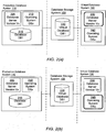
- FIG. 3 shows a high level block diagram illustrating a system environment suitable for making storage efficient copies of information from a production database and provisioning one or more virtual databases using that information.
- the system environment comprises one or more production database systems 110, a database storage system 100, an administration system 140, and one or more virtual database systems 130.
- Systems shown in FIG. 3 can communicate with each other if necessary via a network.
- a production database system 110 is typically used by an organization for maintaining its daily transactions. For example, an online bookstore may save all the ongoing transactions related to book purchases, book returns, or inventory control in a production system 110.
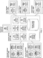
- the production system 110 includes a database server 345, a production DB data store 350, a vendor interface module 335, and a production system library 385. In alternative configurations, different and/or additional modules can be included in a production database system 110.
- the production DB data store 350 stores data associated with a database that may represent for example, information representing daily transactions of an enterprise.
- the database server 345 is a computer program that provides database services and application programming interfaces (APIs) for managing data stored on the production DB data store 350.
- the production system library 385 provides APIs useful for extracting information from the production database system 110.
- the vendor interface module 335 represents APIs provided by a vendor for customizing functionality provided by the database server 345, for example, APIs to retrieve database blocks that changed since a previous time point.
- An example of a vendor interface module is the program code of a database server provided by vendor ORACLE that implements RMAN APIs.
- the vendor interface module 335 mounts the production DB data store 350 of the production database system 110 on the database storage system 100 using a file sharing system similar to the file sharing system 120. Mounting the production DB data store 350 on the database storage system 100 allows transfer of information stored on the production database system 110 to the database storage system 100.
- the production system library 385 may be implemented in different ways depending on the requirements of the vendor interface module 335.
- the vendor interface module 335 loads the production system library 385 in order to call back functions implemented in the production system library 385.
- the production system library 385 may be a shared object file with a ".so” or a ".DLL” file extension that contains executable program code that can be called by a C/C++ executable program or by a JAVA program that uses the JAVA NATIVE INTERFACE for interaction with binary code generated by C/C++ programs.
- the production system library 385 may be implemented using the JAVA programming language and installed in the production database system 110 as a file with ".jar” extension.
- the java program requires a JAVA VIRTUAL MACHINE running on the production database system 110 for execution.
- a part of the production system library 385 may be implemented as an executable ".so" shared object file and another part of the production system library 385 may be implemented as a JAVA program installed as a ".jar” file.
- the vendor interface module 335 responds to requests from database storage system 100, and in response to the requests, collects requested information from the production DB data store 350 and returns the collected information to the database storage system 100.
- the vendor interface module 335 may send request to the database server 345 for retrieving information from the production DB data store 350.
- the vendor interface module 335 loads the program code in the production system library 385 and invokes it to transmit the stream of data for to the database storage system 100 for further processing.
- the vendor interface module 335 may directly interact with the production DB data store 350 instead of sending a request to the database server 345 to retrieve the necessary database blocks.
- the vendor interface module 335 may retrieve the necessary database blocks from storage level snapshots of production databases or clones of production databases instead of a live production database.
- the database storage system 100 retrieves information available in the production database systems 110 and stores it.
- the information retrieved includes database blocks comprising data stored in the database, transaction log information, metadata information related to the database, information related to users of the database and the like.
- the information retrieved may also include configuration files associated with the databases.
- databases may use vendor specific configuration files to specify various configuration parameters including initialization parameters associated with the databases. Copying the configuration files allows a VDB to be created with configuration parameters similar to the source production database.
- the configuration parameters files may be modified by a database administrator using the user interface 395 to customize the VDB configuration for a specific usage scenario.
- the production database may be accessed by a database server 345 using a particular cache size whereas the corresponding VDB may be accessed by a database server 360 using a different cache size.
- the information retrieved may also include information associated with applications using the database, for example, an enterprise resource planning (ERP) application may be using the database and may have data specific to the ERP application.
- ERP enterprise resource planning
- Retrieving the ERP application data allows a similar ERP application to be executed with a VDB created based on the production database system. This is beneficial for usage scenarios where a VDB is created for an environment similar to the production environment, for example, for testing and development.
- a database administrator can use the user interface 395 to specify logic for copying the information that is specific to a production environment as well as logic for appropriately installing the information with a VDB for use by a virtual database system 130.
- information regarding users of the production database may be obtained by using specific APIs or by running specific scripts on the production database.
- the information about the users can be used to facilitate life cycle management of VDBs in the system.
- a database administrator is allowed to use the user interface 395 in order to specify information regarding user accounts to be created and their access permissions. For example, if the VDB is created for testing purposes, test users may be created.on the VDB for test organization whereas if the VDB is created as a standby for the production database, only users with production support roles should have access.
- access permission may specify if a user can provision a privileged VDB.
- privileged VDB is a VDB with full access to non-public information (information that may not be accessible to non-privileged users), for example, social security numbers or credit card information.
- the corresponding un-privileged VDB is a VDB with non-public information masked or scrambled.
- Another example of privileged VDB is a VDB with sensitive data accessible transparently.
- the corresponding un-privileged VDB is a VDB with sensitive information encrypted.
- access privileges are simplified to three levels: administrator, owner, and auditor.
- Administrator has full control of all managed objects including databases and hosts. The control available to an administrator included policy management.
- Owner has access to use of resources, for example, an owner can provision a VDB.
- Auditor can view logs but may not have rights to consume system resources.
- the data stored in the storage system data store 390 can be exposed to a virtual database system 130 allowing the virtual database system 130 to treat the data as a copy of the production database stored in the production database system 110.
- the database storage system 100 includes a point-in-time copy manager 310, a transaction log manager 320, a interface manager 330, a system configuration manager 315, a storage allocation manager 365, a file sharing manager 370, a virtual database manager 375, and a storage system data store 390. In alternative configurations, different and/or additional modules can be included in the database storage system 100.
- the point-in-time copy manager 310 interacts with the production database system 110 by sending a request to the vendor interface module 335 to retrieve information representing a point-in-time copy (also referred to as a "PIT copy") of a database stored in the production DB data store 350.
- the point-in-time copy manager 310 stores the data obtained from the production database system 110 in the storage system data store 390.
- the data retrieved by the point-in-time copy manager 310 corresponds to database blocks (or pages) of the database being copied from the production DB data store 350.
- a subsequent PIT copy request may need to retrieve only the data that changed in the database since the previous request.
- the data collected in the first request can be combined with the data collected in a second request to reconstruct a copy of the database corresponding to a point in time at which the data was retrieved from the production DB data store 350 for the second request.
- the transaction log manager 320 sends request to the production database system 110 for retrieving portions of the transaction logs stored in the production database system 110.
- the request from the transaction log manager 320 is sent to the vendor interface module 335.
- the data obtained by the transaction log manager 320 from the vendor interface module 335 is stored in the storage system data store 390.
- a request for transaction logs retrieves only the changes in the transaction logs in the production database system 110 since a previous request for the transaction logs was processed.
- the database blocks retrieved by a point in time copy manager 310 combined with the transaction logs retrieved by the transaction log manager 320 can be used to reconstruct a copy of a database in the production system 110 corresponding to times in the past in between the times as which point-in-time copies are made.
- the storage allocation manager 365 provides the functionality of saving data retrieved from the production database system 110.
- the point-in-time copy manager 310 may call APIs of storage allocation manager to save blocks of data retrieved from the production database system 110.
- the storage allocation manager 365 keeps track of the various versions of each block of data that may be obtained from the production database system 110. For a given time point, the storage allocation manager 365 can be requested to provide the latest version of a block of data obtained before the given time point.
- the storage allocation manager 365 can also be used for making copies of blocks of data. If a block of data is copied for read-only purposes, the storage allocation manager 365 allocates only sufficient storage to keep a pointer of reference to the exiting block of data. However, if an attempt to write to the copied block of data is made, the storage allocation manager 365 allocates sufficient storage to make an actual copy of the block of data to avoid updating the original block of data.
- the file sharing manager 370 allows files stored in the storage system data store 390 to be shared across computers that may be connected with the database storage system 100 over the network.
- the file sharing manager 370 uses the file sharing system 120 for sharing files.
- An example of a system for sharing files is a network file system (NFS).
- a system for sharing files may utilize fiber channel Storage area networks (FC-SAN) or network attached storage (NAS) or combinations and variations thereof.
- the system for sharing files may be based on small computer system interface (SCSI) protocol, internet small computer system interface (iSCSI) protocol, fiber channel protocols or other similar and related protocols.
- the database storage system 100 may utilize a logical volume manager.
- Sharing a file stored in the storage system data store 390 using the file sharing manager 370 allows a remote computer, for example, the virtual database systems 130 to access the data in the shared file.
- a remote system may be able to read and write from/to the file shared by the storage system data store 390.
- files are organized in a format emulating a given file system disk layout, such as the file system of WINDOWS operating system called NTFS or the UNIX file system (UFS).
- the virtual database manager 375 receives requests for creation of a virtual database for a virtual database system 130.
- the request for creation of a virtual database may be sent by a database administrator using the administration system 140 and identifies a production database system 110, a virtual database system 130, and includes a past point-in-time corresponding to which a virtual database needs to be created.
- the virtual database manager 375 creates the necessary files corresponding to the virtual database being created and shares the files with the virtual database system 130.
- the database administrator for a virtual database system 130 may be different from a database administrator for the production database system 110.
- the interface manager 330 renders for display information necessary for display using the administration system 140.
- a database administrator user can see information available in the storage system data store 390 as well as take actions executed by the database storage system. For example, a database administrator can see the different production databases stored in the storage system data store 390 obtained from different production database systems 110. As another example, the database administrator can request the database storage system 100 to make a PIT copy of a database stored on a production database system 110 at a particular point-in-time.
- the interface manager 330 allows external applications to access information of the database storage system 100.
- the database storage system may provide application programming interface (API) to allow third party vendors to write applications based on database storage system 100.
- API application programming interface
- the interface manager 330 provides web services that allow web applications to access information available in the database storage system 100.
- the database storage system can be part of a cloud computing environment.
- a third party vendor can use web services to implement various workflow scenarios based on VDBs, for example the various workflow scenarios described herein. This allows automation of the workflow scenarios based on VDBs.
- the system configuration manager 315 allows a database administrator using the administration system 140 to setup or change the configuration of the database storage system 100. For example, when the database storage system is being initially setup or at a later stage, the system configuration manager 315 allows a database administrator user or an agent to specify production database systems 110 and virtual database systems 130 to connect to. The system configuration manager 315 also allows a user with appropriate roles and privileges to setup policies specifying the schedule with which the point-in-time copy manager 310 retrieves PIT copies of databases in the production database systems 110 as well as the frequency and the times at which the transaction log manager 320 retrieves updates to online transaction logs from the production database systems 110. In an embodiment, a schedule can specify the frequency and times during the day for the PIT and log retrieval actions or it could be an a periodic schedule specifying the calendar days when the same action should take place.
- policies can be defined by a database administrator and stored in the system configuration manager 315 for various operations associated with the loading of point-in-time copies from production database systems 110, loading of transaction logs from the production database systems 110, purging of information from the database storage system 100 including point-in-time copies of databases and transaction log information, and provisioning of virtual database systems.
- a policy specifies rules for executing the specific operation. For example, a policy may specify the operation to be executed based on a predetermined schedule.
- a policy may determine when to purge PIT copies stored in the database storage system 100 based on number of PIT copies that have been accumulated for a production database.
- a policy may measure storage availability to determine when to purge information.
- old PIT copies of selected databases may be purged.
- the policy may also specify priority of production databases to be used before purging information, for example, low priority database information is purged before purging high-priority database information.
- a policy may determine when to obtain new information from a production database and automatically update VDB information and provision the updated VDB based on the new information.
- a virtual database system 130 includes a database server 360 and a VDB system library 380.
- the database server 360 is similar in functionality to the database server 345 and is a computer program that provides database services and application programming interfaces (APIs) for managing data stored on a data store 350.
- the data managed by the database server 360 may be stored on the storage system data store 390 that is shared by the database storage system 100 using a file sharing system 120.
- the VDB system library 380 contains program code for processing requests sent by the database storage system 100. In alternative configurations, different and/or additional modules can be included in a virtual database system 130.
- FIG. 4 shows the interactions between the database storage system 100 and the production database system 110 to make point-in-time copies of the data stored in a database in the production database system 110.
- the point-in-time copy manager 310 sends 405 a request to the vendor interface module 335 of the production database system 110 for retrieving data associated with a database of the production database system 110.
- the request 405 is sent using the secure shell or SSH network protocol that allows data to be interchanged between two networked devices.
- the request 405 may be sent in response to a request from the administration system 140 or may be configured as a periodically scheduled action.
- the database storage system 100 may be configured to send 405 a request to the production database system 110 at a predetermined time every day.
- the database storage system does not require a process dedicated with the database storage system 100 to be constantly executed on the production database system 480. This is beneficial to the production database system 480 since a process dedicated to sending information to the database storage system 100 may consume significant resources of the production system and may not be desirable. Hence, the database storage system sends the requests 405, 450 whenever it needs information from the production database system 480.
- the production database system 480 sends the requested data to the point-in-time copy manager 310. If the request 405 is the first request for data associated with a database stored on the production database system 110, the production database system 480 sends the data of the entire database in reply. In response to subsequent requests 405, the production database system 480 sends only the data of the database blocks that changed since the last time a reply was sent 430 in response to a previous request 405.
- the vendor interface module 335 sends 410 a request to the database server 345 to collect the information required for the reply 430.
- the vendor interface module 335 also loads the program code available in the production system library 385.
- the database server sends 415 a request for the necessary data to the data store 350 and receives the requested data in response 420.
- the database server 345 sends 425 the requested data to the vendor interface module 335 in response to the request 410.
- the vendor interface module 335 invokes 470 the production system library 385 to package the data received 425 from the database server into a format that can be processed by the point-in-time copy manager 310.
- the production system library 385 sends 430 the requested data stream that is formatted appropriately to the point-in-time copy manager 310.
- the production system library 385 sends 430 the information sent 425 by the database server to the point-in-time copy manager 310.
- the vendor interface module 335 in conjunction with the program code of the production system library 385 builds the data stream for
- the vendor interface module 335 in conjunction with the production system library 385 obtains the required data directly from the data store 350 and sends 430 the data to the point-in-time copy manager 310.
- these embodiments are beneficial when the database server 345 does support appropriate APIs for extracting the necessary information.
- the production system library 385 includes code to analyze the structures of the files of the database stored in the data store 350 and also includes code to process metadata associated with database blocks stored in the data store 350 to find database blocks that changed since a previous time point.
- the reply 430 is a stream of data comprising database blocks that may be stored in multiple files in the data store 350.
- the stream of data corresponding to the reply 430 may interleave information associated with the different database blocks, for example, database blocks obtained from different files may be interleaved.
- the program code of the point-in-time copy manager 310 processes the data stream without assuming any particular order of the database blocks received in the data stream.
- These database blocks may also belong to different databases.
- FIG. 5 shows a flowchart of the process illustrating the processing of a stream of data received from a production database system 110 by the point-in-time copy manager 310.
- the point-in-time copy manager 310 receives 510 the stream of data including blocks changed since the last PIT copy.
- the point-in-time copy manager 310 processes the stream of data to identify 515 database blocks in the stream of data.
- Each database block includes metadata that contains information regarding the database block, for example, database object this block belongs to, the size of the database block, the file from which the database block was obtained, the offset within the file where the database block was stored, and a log sequence number that specifies the order in which database blocks are updated in the database in the production database system 110.
- the point-in-time copy manager 310 analyzes 520 the metadata for each database block to determine if the database block needs to be stored in the storage system data store 390 or it can be eliminated.
- the log sequence number in the metadata of the database block may indicate that even though the production system library 385 sent 430 the database block along with the data stream, the database block was never updated since the last reply 430 received from the production system library 385.
- the block need not be stored in the storage system data store 390 and can be skipped.
- Other examples of database blocks that need not be stored include temporary database blocks, session specific database blocks, and empty database blocks that have no data written in them.
- Another example of database blocks that need not be stored includes database blocks that are not meaningful or inaccessible to database software. Another example includes database blocks that have been marked deleted, emptied, or invalidated by database software.
- the information sent 430 by the production database system 480 included unnecessary blocks that were eliminated after the data stream was received by the database storage system 100. In other embodiment, some or all of the unnecessary blocks may be eliminated while the data stream is built by the production system library 385. In this embodiment, the data stream sent 430 to the database storage system 100 by the production database system 480 is reduced in size resulting in efficient communication between the two systems.
- the database storage system may achieve significant savings in terms of storage required for the database files compared to the production database system for the data corresponding to the same database.
- the storage space occupied by the data corresponding to a production database in the storage system data store 390 may be a quarter of the space occupied by the production database in the production DB data store 350. Note that the entire information corresponding to the production database system is obtained by the first PIT copy. Subsequent PIT copies obtain only the changed information in the production DB and can be much smaller than the information contained in the first PIT copy.
- the point-in-time copy manager 310 determines 525 that a database block in the data stream can be skipped, the point-in-time copy manager 310 proceeds to identify 515 the next database block for processing.
- the point-in-time copy manager 310 uses the database block size available in the stream metadata to identify database block boundaries in the stream of data. Each block is then processed accordingly.
- the point-in-time copy manager 310 determines that the database block in the data stream needs to be stored in the data storage system data store 390, the point-in-time copy manager 310 analyzes the database block metadata to map 530 the database block to a database file and a location within the file. The point-in-time copy manager 310 sends 435 a request to the storage allocation manager 365 to save 535 the database block. The storage allocation manager 365 stores 440 the database block in the appropriate file associated with database block in the storage system data store 390. The point-in-time copy manager 310 checks 540 if the data stream is processed completely. If there is unprocessed data remaining in the data stream, the point-in-time copy manager 310 proceeds to identify the next block of data for processing.
- the storage allocation manager 365 may keep several different versions of the database block in the storage system data store 390 corresponding to the data in the database block if it is updated at different points in time.
- the file in which the database block is saved comprises a file header including metadata associated with the file and a sequence of database blocks.
- Each vendor specific database server 345 organizes the database information as a set of files that the database server 345 is capable of processing.
- the organization of information using the set of files for the database may be vendor specific and the database storage system incorporates the program logic to organize the database information in vendor specific organization of files.
- the point-in-time copy manager 310 creates a set of files structure that may be similar to the set of files of the database in the data store 350.
- the information in the storage system data store 390 may include multiple versions of the database blocks, each corresponding to updated information at different points in time.
- the storage allocation manager 365 stores the database blocks associated with the files in an efficient manner, such that a copy of a database block is made only if the database block was updated for a point-in-time. For example, if a block B1 is updated at time T1 but not at time T2, whereas a block B2 is updated at time T1 and T2 both, the data structure of the storage system data store 390 does not keep a copy of the database block B1 for time T2 whereas it keeps a version of the database block B2 for time T2.
- FIG. 4 also illustrates the interaction of the transaction log manager 320 with the production system library 385.
- the transaction log manager 320 retrieves incremental changes made to the transaction logs in a database in the production database system 110 since a previous time point.
- the request 445 is sent using the secure shell or SSH network protocol.
- the request 445 may identify the database for which information is required and provide a time value corresponding to the previous time point the transaction log information was received.
- the production system library 385 sends 450 the requested information in response to the request 445 to the transaction log manager 320.
- the vendor interface module 335 may obtain the requested information either by calling the database server 345 APIs or by directly interacting with the data store 350, as described above.
- the incremental changes to the database logs obtained from the production database system 110 are saved by the transaction log manager 320 by sending a request 460 to the storage allocation manager 365 that stores 440 the information in the storage system data store 390.
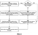
- FIG. 6 shows a process for copying the transaction log files from a production database system 110 to the database storage system 100.
- the transaction log manager 320 sends 600 a request to the production database system 110 for retrieving the updates to transaction logs since the last update was received by the transaction log manager 320.
- the transaction log manager 320 receives 610 the response from the production database system 110 as a data stream.
- the transaction log manager 320 analyzes the data stream received to determine 620 the log file to which the transaction log data needs to be written. It is possible that the data received in a data stream needs to be written to multiple log files.
- the transaction log manager 320 writes 630 the online transaction log data from the data stream to the appropriate log file.
- the transaction log manager 320 waits 640 a predetermined interval of time between log file updates and sends 650 the next request to the production database system 110 to check if new updates to the transaction log updates are available. If no updates were made to the production database during this time interval, the production database system 110 informs the transaction log manager 320 accordingly. If no new updates to transaction log for this time interval are available, the transaction log manager 320 waits 640 for another interval of time. If the response from the production database system 110 indicates that updates to transaction logs are available, the transaction log manager 320 sends 600 the next request to the production database system 110 for retrieving the next update to the transaction logs.
- the incremental changes to the transaction logs may be obtained by the transaction log manager 320 much more frequently compared to the point-in-time copy made by the point-in-time copy manager 310.
- the point-in-time copy manager may make a point-in-time copy of a database stored in the production database system 110 once a day whereas the incremental changes to the transaction logs may be obtained by the transaction log manager 320 every five minutes.
- Obtaining incremental changes to the transaction logs at a high frequency provides the ability to recreate a copy of a database from the production database system 110 at a time point in between the times that a point-in-time copy is made by the point-in-time copy manager 310.
- the production database system 110 may reuse the transaction log files in a circular fashion, thereby overwriting the previous log files. However, the database storage system 100 creates a new log file each time it determines to close the log file to which data is currently being written to start writing to a different log file.
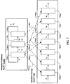
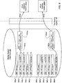
- FIG. 7 compares the log files of the production database system 110 with the log files of the database storage system 100.
- the log files 710 for the production database system represent online transaction log files. A limited number of files are typically allotted for storing the online transaction logs. For example, FIG. 7 shows three files 710(a), 710(b), and 710(c) allotted by the production database system 110 for storing the online transaction logs.
- the arrows 730 indicate a change of the transaction log file to which the transaction logs are being written by the production database system 110 at a given time Ti (the times T1, T2, T3, are assumed monotonically increasing). For example, at time T1, the production database system 110 stopped writing the transaction logs to the file 710(a) and started writing the transaction logs to the file 710(b). Similarly at time T2, the production database system 110 stopped writing the transaction logs to the file 710(b) and started writing the transaction logs to the file 710(c). At time T3, the production database system 110 stopped writing the transaction logs to the file 710(c) and decided to reuse the transaction log file 710(a).
- the production database system 110 Before reusing a transaction log file, the production database system 110 ensures that the transaction logs available in the transaction log file are applied to the appropriate database.
- the log file changes at times T4, T5, T6 are similar to the changes described above.
- the production database system may typically reuse the transaction log files in a circular fashion to reuse storage.
- the database storage system does not use a circular reuse strategy for log file data because the database storage system keeps the historical information for a much longer time determined by the log retention policy, based on the transaction logs. Keeping the historical information based on the transaction logs provides the ability to create VDBs for past time points. VDBs can be created for past time points as long as transaction logs necessary to reconstruct the database snapshot corresponding to the past time points are available. A strategy based on circular reuse of transaction log files results in earlier transaction logs being overwritten. Hence, a database system using circular reuse strategy for the log files can only reconstruct database snapshots based on the transaction logs for recent time points for which the transaction logs have not been overwritten.
- the logs files 720 stored in the database storage system 100 are retained log files.
- the arrow 740 represents transfer of information from a transaction log file 710 of the production database system 110 to the retained log file 720 of the database storage system 100.
- Each arrow 740 may correspond to several requests 445 being sent from the transaction log manager 320 to the production database system 110 and several responses being sent 450 by the production database system 110 that are processed by the transaction log manager 320 and stored.
- arrow 740(a) indicates copy of information from log file 710(a) to 720(a) during the time interval T1 to T2.
- the production database system started writing transaction logs to file 710(b).
- the database storage system creates a new log file 720(b) and arrow 740(b) indicates the transfer of transaction log information from file 710(b) to log file 720(b).
- the database storage system creates a new log file 720(d).
- Arrow 740(d) indicates copy of transaction log information to log file 720(d).
- the transaction log information from the same transaction log file of the production database system 110 may be copied to multiple log files in the database storage system 100 at different times.
- the information in transaction log file 710(a) is copied to log file 720(a) between T0 and T1, to log file 720(d) between T3 and T4, and to log file 720(g) between time T6 and T7.
- the database storage system 100 avoids reuse of the log files to keep the transaction log information for as long as possible as determined by the log retention policy. This allows a user to recreate a snapshot of a database at a previous time point for which the transaction log information is available.
- FIG. 8 illustrates the information obtained at different points in time by the database storage system 390 from various production database systems 110 that is stored in the storage system data store 390.
- FIG. 8 shows information related to two databases, DB1 and DB2 obtained from the production database system 110.
- the information 850 correspond to data obtained for database DB1 whereas the information 860 correspond to the data obtained for database DB2.
- the information 850 or 860 comprises a set of database blocks and a set of transaction logs.
- the information 850(a) represents the first PIT copy of database DB1 obtained from the production database system 110.
- the information 850(b) represents the first transaction log update for the database DB1 since the first PIT copy and the information 850(c) represents the second transaction log update for the database DB1 since the first PIT copy.
- the information 850(d) represents second PIT copy of the database DB1.
- the information 850(d) stores only the database blocks that were changed in the database DB1 since the first PIT copy was made.
- the information 850(e) represents the first transaction log update for the database DB1 since the second PIT copy.
- the information 860 correspond to the database DB2.
- the time Ti indicated next to a information 850 corresponds to the time that information was copied in the structure.
- the time Ti represents the time of the last update made to the database blocks before the PIT copy was made.
- the time Ti represents the time of the last transaction log in the corresponding set of the transactions logs stored.
- FIG. 8 is a flowchart of the process for creating a virtual database.
- the virtual database manager 375 receives 905 a request to create a virtual database for a Virtual Database System 130.
- the request to create a VDB may be received from the administration system 140.
- the request to create a VDB may include details of the production database system 110 and the corresponding database that needs to be made available as a VDB, the virtual database system 130 for which the VDB needs to be created, and a past time point Tn for which the database snapshot needs to be created as a VDB.
- the virtual database manager 375 identifies 910 the recent most PIT copy associated with time Tj, such that Tj ⁇ Tn.
- the virtual database manager 375 further identifies 915 a portion of the log file updates for the time period from Tj to Tn.
- the read/write file structure 870 is created 920 by making storage efficient copies of the database blocks in the identified PIT copy and the appropriate portions of the log files.
- the appropriate transaction logs can be applied to a VDB created based on a PIT copy so as to create a snapshot of the source database for a time point that occurs after the PIT copy was made.
- a VDB can be created for any time point in between PIT copies by appropriately applying the transaction logs to a previous PIT copy.
- a PIT copy may have been made from a production database at midnight on a particular date.
- a VDB can be created based on the state of the production database at a particular time later during the day, for example, 10:25am, even though no PIT copy was made at that particular time. The changes in the production database from midnight to the particular time are obtained from the transaction logs.
- the virtual database manager 375 sends 935 (indicated by arrow 830 in FIG. 8 ) handles to the read/write file structure to the associated virtual database system 130.
- the virtual database manager 375 makes the file structures available to the virtual database system 130 by sending a request to the file sharing manager 370.
- the file sharing manager 370 in response, shares the appropriate files with the virtual database system 130 using the file sharing system 120.
- the virtual database manager 375 also sends 930 a request to the virtual database system 130 to perform recovery 930 of the new virtual database by applying the appropriate retained logs to the database blocks.
- the recovery of the database is automatically performed by the database when the database server starts in the virtual database system 130.
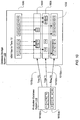
- FIG. 10 indicates how storage efficient copies are made to create a read/write file structure representing a VDB.
- the structures 1010 represent the files corresponding to a database on the production database system 110.
- the structures Fi and Gi represent database blocks stored in the files 1010 respectively (Fi refers to F1, F2, F3,... and similarly Gi refers to G1, G2, G3,).
- the arrows 1015 represent the process of making PIT copies at different time points Ti.
- the first PIT copy 1030 made at time T0 needs to copy all the necessary database blocks of the database. For example, F1i represents a copy of block Fi and block G1i represents a copy of block Gi.
- the PIT copy 1035 made at time T1 copies only the blocks that changed since the last PIT copy and may copy much less data compared to the first PIT copy. Similarly at time T2 another PIT copy 1040 is made copying the database blocks that changed since the previous PIT copy 1035.
- the VDB file structures 1050 are created for time point T2.
- the blocks V11, V12,..., V25 may be implemented as pointers to the actual database block that stores the data.
- V11 represents the information in block F1 and since the block F1 was never updated during copies made at time T1 and T2, V11 points at F11.
- V12 represents the information in block F2 and since F2 was updated at time T1, V 12 points at the block F22.
- V13 corresponds to block F3 that was updated at time T2 and points at the block F33.
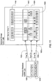
- FIG. 11 illustrates the file structures 1150 created for time point T1. Note that U13 corresponding to block F3 points at F13 since the block F3 was never updated for time point T1. Also, U14 points at block F24 corresponding to block F4 copied at time T1. None of the structures in 1150 point at PIT copy 1040 since the PIT copy 1040 was made after the time point T1.
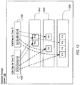
- FIG. 12 illustrates how database blocks stored on the storage system data store 390 may be shared by file structures created for different VDBs.
- FIG. 12 shows the file structures corresponding to the file 1005 of the production system database 110 created for VDBs as illustrated in FIG. 10 and FIG. 11 .
- the block V 13 and V14 of the file structure C50 point at the latest copy of the blocks F33 and F34 that are not shared with the VDB files 1150 for time T1.
- block V11 ofVDB files 1050 at T2 shares block F11 with block U11 of VDB files 1150 at T1.
- block V12 of 1050 shares database block F22 with block U12 of 1150.
- the sharing of blocks across multiple VDBs results in efficiently utilization of data stored in the storage system data store 390.
- one of the VDBs attempts to write to a shared database block
- a copy of the shared database block is made for the VDB attempting to write.
- the remaining VDBs that shared the database block continue to share the original database block. Accordingly, any changes to the copied database block are not visible to the remaining VDBs since the changes are specific to the VDB that is writing to the database block.
- a VDB may be created using a point-in-time copy of another VDB as a source.
- VDB1 is created and provisioned to a virtual database system 130.
- Database blocks associated with the VDB are copied when the virtual database system 130 writes to the database blocks for the first time.
- Point-in-time copies of VDB1 are also made based on a predefined schedule. This allows a user to create a second virtual database VDB2 based on a point-in-time copy of VDB1.
- Transaction logs of VDB1 are also stored, allowing a user to create the second virtual database VDB2 based on any previous state of VDB1 that may be in-between point-in-time copies of VDB1.
- FIG. 13 further illustrates incorporation of log files in the VDB file structures 1350 that corresponds to a database snapshot for a time point T1+t2 that occurs before T2.
- the log file data L1 is copied by the transaction log manager 320 at time T1+t1 and the log file data L2 is copied at time T1+t2.
- Additional log data L3 written in the production database system 110 is not shown copied to the database storage system and may be copied at a time after T1+t2.
- the file structure 1350 created for a VDB includes structure VL11 that points to the appropriate log file data representing the log information copied between time T1 and T1+t2, represented by L1 and L2.
- the logs pointed at by structure V11 may be applied to the database blocks 1035 using the database recovery process.
- the virtual database system 130 Since the structure 1050 illustrated in FIG. 10 , structure 1150 illustrated in FIG. 11 , or structure 1350 illustrated in FIG. 13 are read/write structures, the virtual database system 130 is allowed to read from these structures as well as write to them.
- the virtual database system 130 writes to a block Vij, space is allocated for the database block and the data of the corresponding database block copied to the space allocated. For example, if the virtual database system 130 writes to the block V 11, space is allocated and block F11 copied to the allocated block. Hence the original copy of the block F11 is maintained as a read only copy and the virtual database system 130 is allowed to write to a copy of the appropriate database block created specifically for the virtual database system 130.
- FIG. 14 illustrates an example of the life cycles of a database in a workflow for making changes to the database or to applications that depend on the database.
- copies of a production database 1405 may be made for several purposes including development, tuning, testing, quality assurance, certification, training, and staging. Making copies of large databases by conventional means can be a slow process. Furthermore, running different copies of databases on different machines results in inefficient usage of the hardware.
- Various workflow scenarios associated with databases can be simplified and made highly efficient by creating virtual databases instead of making physical copies of the databases. Multiple virtual databases can be stored in a database storage system 100 and the available resources of the system can be utilized efficiently.
- the steps performed in a workflow scenario based on VDBs can be significantly different from the operations performed for the same workflow scenario using conventional systems. These steps may be executed by a database administrator of the database storage system 100 or executed automatically using a script. Various operations associated with a virtual database are described below.
- the link operation provides information necessary to access a database on a production database system 110 to the system configuration manager 315 of the database storage system 100.
- the information necessary to access the database enables the database storage system 100 to retrieve data from the production database system 110.
- the information may include the name of the database, network address of the production database system 110 hosting the database, and access control information.
- the database storage system may communicate with the production database system 110 to validate the information of the database.
- the database storage system 100 can retrieve database blocks from the linked database in the production database system 110 and store them in the storage system data store 390.
- the database blocks stored in the storage system data store 390 can be used to create virtual databases.
- linking may specify that only a part of source database needs to be copied rather than the whole source database.
- a part of the source database could be a table space, a set of one or more tables, a subset of a table, or a set of subsets of tables.
- a user can specify a script for computing a part of a database.
- the load operation retrieves data from a database of the production database system 110 for storage in the database storage system 100.
- the database needs to be linked to the database storage system 100 before the database can be loaded. If the load operation is retrieving the data of the database for the first time, the entire data available in the database is retrieved. As a result, the first load operation can be slow and may take several hours or days depending on the size of the database and the network bandwidth based on state of the art hardware. Subsequent load operations may take significantly less time since they retrieve only changes in the database since a previous load operation.
- the load operation is performed periodically to obtain the changes to the database on an ongoing basis.
- the load operation may obtain database blocks of the database and/or transaction logs representing updates to the database since a previous point in time.
- the input required for the load operation includes information identifying a previously linked database. If only a part of the source database is specified in linking, only that part will be loaded.
- the load operation can also incrementally update information available in a VDB.
- the information obtained from the production database system 110 by a database storage system 100 may be updated periodically.
- the information provisioned to the virtual database system 130 can also be updated. It is possible that the data in the VDB is updated by the virtual database system 130.
- the incremental load identifies the updates made by the virtual database system 130 and compares them with the changes retrieved from the production database system 110. If there are no conflicts in the two sets of updates, the load operation can succeed by applying the changes of the production database system 110 to the VDB. If there are conflicts, a report of the conflicts may be presented to a database administrator and input requested from the database administrator to help resolve the conflicts.
- the conflicts between the updates from the two sources are detected by identifying the database blocks affected by the two updates. If there is no overlap between the database blocks of the two sets of updates, the database storage system 100 determines that there are no conflicts. If only part of source database is specified in linking, only changes to that part will be loaded.
- the provision operation creates a virtual database in the database storage system 100 and makes it available to a virtual database system 130.
- the virtual database may be created based on a point-in-time copy of a source database or a point-in-time copy of another virtual database.
- One or more read/write files may be created for the VDB and shared with the virtual database system 130 using the file sharing system 120.
- the read/write files include structures that point to database blocks stored in the storage system data store 390.
- the input required for the provision operation includes information identifying a previously linked and loaded database or an existing VDB, a previous time point corresponding to the desired state of the database, and information identifying a virtual database system 130 for which the virtual database is being provisioned.
- a part of a VDB could be provisioned.
- parts from different VDBs may be provisioned together to form a new VDB.
- several VDBs may be provisioned together as a group using application specific coordination scheme. These group oriented provisioning may involve provisioning or coordination of provisioning of application logic or configuration.
- the bookmarking operation marks an application significant point in time in one or more virtual databases.
- the resulting "bookmark" can be used to direct provisioning operation.
- the operation is triggered by user or external program through administration system 140.
- Database storage system 100 returns a token as the resulted "bookmark" is stored in database storage system 100.
- user or external programs can provision the VDB or the group of VDBs to the same application significant point in time using returned token.
- an external program may wish to capture production database in certain state, such as right after a massive batch processing run.
- User could invoke bookmarking operation via administration system 140 and save returned token. Later, user can provision the VDB to the same state by supplying saved token.
- tokens are in the form of string.
- the refresh operation corresponds to the database storage system 100 periodically updating a VDB based on the latest information from the source database system 110.
- a VDB may be used for a reporting system that generates report for users to view.
- the refresh operation automatically loads the latest information periodically from a production database system 110, for example, daily.
- the VDB being refreshed is shutdown.
- the VDB is updated with the latest point-in-time copy of the production database system 110 and the VDB restarted. Accordingly, the users of the corresponding virtual database system 130 see the latest reports based on the latest point-in-time copy of the data in the production database system 110.
- the VDB may also be refreshed based on transaction logs obtained in between point-in-time copies obtained from production database system 110.
- the input required for a refresh operation includes information identifying a VDB to be refreshed and a schedule for refreshing the data.
- the pre-script operation corresponds to execution of special purpose instructions that perform specific tasks before performing another database storage system 100 operation.
- a pre-script operation may be performed before provisioning a VDB or a load of a database from the production database server 110.
- a database may be used along with applications that require application specific data stored outside the database.
- a pre-script operation can be executed to load the application specific data to the database storage system 100.
- the input to the pre-script operation may include an executable script specifying the operations to be performed and details of the database storage system 100 operation before which the pre-script operation is performed.
- the post-script operation corresponds to execution of special purpose instructions that perform specific tasks after performing database storage system 100 operation.
- a post-script operation may be performed after provisioning a VDB to a virtual database system 130. Testing and development of an application using the database in the production database system 110, can be performed by running a similar application using a testing or development virtual database system 130.
- the application specific data copied from the production database server 110 by the pre-script operation may have to be further copied to the virtual database system 130 that runs a corresponding application.
- the instructions for copying the application specific data from the database storage system 100 to the virtual database system 130 are executed as a post-script operation after the provision operation.
- the input to the post-script operation includes an executable script specifying the operations to be performed and details of the database storage system 100 operation after which the post-script operation is performed.
- pre-script and post-script operations can be associated with various VDB operations.
- pre-script operation can be performed before a refresh operation and a corresponding post-script operation performed after the refresh operation to allow copy/installation of specific information before/after the refresh operation.
- prescript/post-script operations may be associated with other VDB operations including link, load, provision, and export among other operations.
- pre-scripting/post-scripting operations allow scrubbing of data by using compression, masking, or removing data including columns or rows of database tables.
- Pre-scripting and post-scripting allows dealing with application data associated with applications using the source database and/or the VDB.
- Pre-scripting and post-scripting allows management of system environment issues associated with provisioning of VDBs and allows starting/stopping activities before/after a VDB is provisioned.
- the share operation corresponds to granting permission to another user in order to allow the user to access a VDB.
- the share operation may include the step of creating a new VDB and provisioning it for sharing with a new user or a set of users. For example, in a test and development environment, after reaching a particular stage of development using a VDB, the VDB may be shared with test users.
- the input required for a share operation may include information a VDB to be shared, information identifying users with whom the VDB is shared and access control information identifying the level of permissions granted to.the users.
- the export operation copies the information available in a database from one computer to another. Typically the information is copied to a target computer for assembly as a database.
- a stage operation corresponds to an export operation that copies the database information to a staging server.
- a staging server is typically used for performing system level testing of a database before using changes made to the database or to a database application in a production environment.
- the input to the export operation includes, information identifying the VDB to be exported and information identifying the target machine to which the data from the VDB needs to be exported.
- the mask operation corresponds to altering or skipping specific information in a database when the information in the database is being copied. For example, when a copy of a database is made, sensitive information in the source may not be copied to the target. Another example is that data is scrambled when database is provisioned. Examples of sensitive information include credit card information or social security numbers.
- Example scenarios where database information is masked include making a copy of a production database for testing purposes. Users of the database that perform testing using a VDB may not need the sensitive information stored in the production database system 110.
- Other operations that can transform data being copied from a source database include compress and encrypt. The compress operation transforms the data by preserving the original information but the converting the format of the data so that it occupies less space when stored.
- the encrypt operation transforms the data to a format that cannot be read by applications that do not have the logic to decode the encrypted information.
- the inputs to the mask, compress, or encrypt operations include information identifying a source VDB and a target database.
- the target database may itself be a VDB or the data can be exported to a conventional system.
- the purge operation deletes information not needed from a VDB.
- information is purged when it occupies large amount of space and is not needed anymore.
- a database may be storing event data associated with events occurring in a system over a long period of time. Old data that is not needed any more or data that has been archived can be purged from the database.
- the purge operation can be performed when the database information is copied by skipping the information to be purged from the copy operation.
- the inputs for a purge operation can include information identifying a source VDB and a target database.
- the target database can be a VDB or it can be a conventional database.
- the extract, transform, and load (ETL) operations refers to typical operations performed in a data warehousing project.
- the extract step retrieves data from a source, the transform step modifies the data based on certain operational needs and the load operation loads the data to a target system.
- the input required by the ETL operations includes information identifying a source database, information identifying a target database, and operations to be performed for transformation of the data.
- the inputs for the ETL operation can include information identifying a source VDB and a target database.
- the target database can be a VDB or it can be a conventional database.
- the replicate operation transfers changes from the data stored in a source storage system to a target storage system.
- the data being replicated can either be a VDB or the data stored in the storage system data store 390, corresponding to the database blocks obtained from one or more production database systems 110.
- the source and target storage systems need to be setup appropriately for the replicate operation.
- Program code for replication on the source storage system may periodically identify the changes in the data stored in the source storage system and send the changes to the target storage system.
- program code on the target storage system may receive the changes form the source storage system and process them appropriately to incorporate the changes.
- Replication can be used for high-availability by mirroring the data from the source storage system to the target storage system.
- the target storage system is available for use in case the source storage system becomes unavailable for some reason.
- the inputs for the replicate operation may include information identifying a source system and a target system.
- the backup operation creates a copy of the data available in a storage system such that the backup copy of the storage system can be used to reconstruct information of the original storage system in case the original data is lost.
- the restore operation recovers the information available in the backup copy and reconstructs the information. Note that any changes in the original storage system since the backup was created may be lost, unless the update information is saved in some format.
- the backup information is stored on large storage systems with possibly slow retrieval speed, for example, tape backup systems.
- VDB operations based on the concepts defined herein can be defined and used for datacenter workflow automation. VDB operations can also be created by combining existing VDB operations. Different workflow scenarios that utilize the above operations based on VDBs or database storage systems 100 are described below. For each workflow scenario, a brief description of the scenario based on conventional systems is compared with the scenario based on virtual databases.
- FIG. 15 illustrates a scenario for a test and development workflow based on a production environment using conventional databases.
- the production database system 1505 includes a database 1500 used in a production environment. Testing and development of software used in the production environment by conventional systems may require multiple copies of data stored in the database 1500.
- the database 1500 is copied 1550 to the data store 1515 of a development system 1510. Development activities may be performed on the development system 1510 for certain period of time. Periodically, the database in data store 1515 is further copied to a data store 1525 in a test system 1520 for performing testing of the software and/or the database. Issues found in the test system 1520 may provide feedback 1575 that may require further development activities.
- the process of development and testing may be repeated multiple times.
- the database may be copied from the test system 1520 to the data store 1535 of the quality assurance (QA) system 1530 for quality assurance that may include testing of performance, system integration, certification, and user acceptance.
- Feedback 1570 based on QA system 1530 may require further development using the development system 1510.
- the overall process of development, testing and QA may be repeated multiple times.
- the database may be further copied to the data store 1545 of a staging system 1540.
- the final changes in the software or database are propagated 1560 to the production database system 1505, for example, via an upgrade procedure.
- FIG. 16 illustrates the scenario for the test and development workflow based on virtual databases.
- a database 1500 from the production database system 1505 is linked and loaded 1665 to the database storage system 100.
- a virtual database corresponding to the database 1500 is provisioned 1640 to the development system 1610.
- the virtual database created for the development system 1610 can be refreshed 1670 multiple times based on a schedule.
- the VDB is shared with a test system 1615, thereby providing appropriate access to the users of the test system 1615.
- Sharing of the development VDB with the test VDB may involve creating a test VDB based on a point-in-time copy of the development VDB. Feedback 1575 provided by the test system 1615 may require repeated provision 1640, refresh 1670, and share 1645 operations.
- the VDB is further shared 1650 with a QA system 1630 and stored in the data store 1635. Sharing of the test or development VDB with the QA system may require creating a QA VDB based on a point-in-time copy of the corresponding test/development VDB.
- the development VDB is exported to the QA system.
- a VDB may also be staged 1655 directly to the data store 1645 of the staging system 1640.
- production server may be located in one site of the organization whereas development and testing may be performed in another site of the organization.
- the other site performing development and testing may be offshore, resulting in slow network communication between the two sites.
- the development system 1510 and test system 1520 shown in FIG. 15 may be available on one site and the remaining systems including the production system 1500, the QA system 1530, and the staging system 1540 on a different site.
- FIG. 17 shows the interaction between the various systems for this scenario.
- the sites are named first site 1765 and second site 1760.
- a database storage system 1715 is available on the first site 1765 and a second database storage system 1705 is available in the second site 1760.
- a database stored in the production database system 1505 is linked and loaded 1775 into the database storage system 1715 in the first site 1765.
- the data corresponding to the database is replicated 1725 from database storage system 1715 to the database storage system 1705.
- the replication operation 1725 may also be combined with other operations including masking, purging, compression, and encryption.
- the information may have to be masked and purged since the development/testing may be offshore and the users in the second site 1760 may not have access to specific information available in the production database.
- the information may also be compressed to reduce the time taken to transfer the data over the network and encrypted to avoid the data being stolen.
- the database is provisioned 1740 and refreshed 1770 for the development system 1610 and shared 1745 with the test system 1615 as necessary. Changes made to the database stored in the storage system data store 1710 as a result of the testing and development can be propagated back to the database storage system 1715 and stored in the storage system data store 1720. The propagation of these changes can be performed via a replication 1730 operation that can be combined with compression and encryption.
- the updated database in database storage system 1715 is exported 1750 to the QA system 1630 and/or exported 1755 to the staging system 1640.
- FIG. 18(a) illustrates the scenario for backup and restore of databases.
- the backup system 1815 may store the backup data in persistent memory, for example, a large disk storage unit and/or use a tape backup unit.
- the operation copy 1825 corresponds copying database blocks in the database 1810 or to exporting the data in the database 1810 to one or more files, copying the files to the backup system 1815 to be stored in the data store 1820.
- Some of the database systems 1810 may store snapshots of the databases on the system that also need to be backed up.
- a database system 1810 may mirror a database using another database system and synchronize changes in the mirrored database with the original database 1810.
- the mirror database may need to be backed up into the backup system 1815.
- additional standby databases may be used along with a database 1810 to protect the data from failures and disasters.
- the standby databases may also be backed up using the backup system 1815.
- An example of a vendor specific utility that helps with backups of databases is RMAN for use with ORACLE databases.
- FIG. 18(b) illustrates the scenario for restore of databases using a database storage system 1890, replacing the need for traditional backup and recovery.
- the database storage system 1890 itself acts as storage for copies of the databases 1860 in the database systems 1865.
- the copy operation 1825 is obviated by the link and load operation 1830.
- the advantages of using link and load operations supported by the database storage system 1890 are that it transfers much smaller amount of data from the database 1860 to the database storage system 1890 compared to full and incremental backups. Furthermore, subsequent updates of databases 1860 performed using the link and load 1830 operations transfer only the changes that occur in the databases 1860 on an ongoing basis, without the need to repeat a full load.
- the amount of data transferred from the databases 1860 to the storage system data store 1840 is significantly smaller than in a backup solution. Therefore, much less storage space is occupied by the data in the storage system data store 1840 and the transfer of data from the databases 1860 to the storage system data store 1840 requires much less time.
- the data available in the storage system data store 1840 is backed up 1855 using a backup system 1845.
- the backup operation 1855 may initially copy the entire data available in the storage system data store 1840 and subsequently copy 1855 incremental changes of the data stored in the storage system data store 1840.
- the amount of data stored in the storage system data store 1840 can be significantly less than the amount of data stored by the data store 1820 of the backup system 1815 since only changes made to the databases 1860 are stored in the storage system data store 1840.
- the time required to link/load the data in databases 1860 to the storage system data store 1840 combined with the time taken to backup 1855 the data of storage system data store 1840 can be significantly less than the time taken by the backup operations 1825 in a large enterprise, especially when it comes to the load and time required from the source databases.
- information in a source database is periodically copied to a target database.
- information may be copied from a source database to a target database used for recovery of information in case the source database is destroyed in a disaster (the process known as disaster recovery).
- Information may also be copied to one or more databases to increase the availability of the data to users. For example, if the source database is down for maintenance or for other reasons, the target database can be made available to the users.
- information is copied from a source database to a target database that is used for reporting purposes.
- the execution of reports on a production database system may cause significant load on a database. Since the production database system is used for transaction processing, it is preferred that a different server synchronized with the database on the production database system be used for generating reports.
- the target database is updated frequently to provide up-to-date reports using the reporting infrastructure.
- Another scenario that requires copy of information from a source database to a target database is the migration of databases from one machine to another.
- Migration of databases may be required when an enterprise upgrades software to newer versions, for example, upgrades to a newer version of operating system, a newer version of database management system, a newer version of an application, or upgrade to new hardware.
- Migration of databases may also be required from one physical location to another, for example, when a company is acquired by another company.
- FIG. 19 illustrates a system environment for copying information from one or more source database systems 1905 to target database systems 1905.
- FIG. 19 illustrates the copy or transfer 1950 of information from a source data store 1935 in a source database system 1905 to a target data store 1940 in a target database system 1910.
- information from one source data store 1935 may be transferred to more than one target data store 1940.
- information in more than one source data store 1935 may be transferred 1950 to a single target data store 1940.
- the source database systems 1905 and the target databases 1910 may be situated in different physical locations, for example, geographically separate locations illustrated as the first site 1955 and the second site 1960. Typically machines situated in different physical locations have slow network communication compared to machines situated in the same physical location. Embodiments described herein apply to source and target database systems situated in the same physical location as well as different locations.
- FIG. 20 illustrates a system environment based on virtual databases stored in database storage,systems 100 for implementing a workflow scenario conventionally implemented as shown in FIG. 19 .
- the data in the databases stored in source data stores 1935 is linked and loaded 2020 to the storage system data store 2025 of the source database storage system 2005.
- the operation 2020 may include subsequent load operations performed to update the data in the storage system data store 2025 based on updates in the source database system 1905.
- the data in the storage system data store 2025 of the source database storage system 2005 is transmitted 2015 to the storage system data store 2030 of the target database storage system 2010.
- the operation 2015 may be a copy operation that copies the entire information in the storage system data store, a backup operation, or a replicate operation that incrementally copies updates in storage system data store 2025 to the storage system data store 2030.
- the operation 2015 may copy the entire data in the storage system data store 2025.
- the changes in the storage system data store 2025 may be copied periodically to the storage system data store 2030.
- the changes to storage system data store 2030 may be applied to VDBs provisioned to target database systems 1910 using the refresh operations. If any changes are made to the VDBs by the target database system 1910, the changes may be propagated back to the storage system data store 2025.
- the operation 2030 makes databases stored in the storage system data store 2030 available to target database systems 1910.
- the operation 2030 may correspond to provisioning a VDB from the storage system data store 2030 to target database systems 1910.
- the operation 2030 may correspond to exporting a database to the target database systems 1910.
- VDBs provisioned 2035 by the source database storage system 2005 to VDB systems 2040.
- Equivalent VDBs can be created using the data in the target database storage system 2010 and provisioned 2045 to VDB systems 2050. Any changes made to the VDBs in the source database storage system 2005 are automatically saved in the storage system data store 2025 and get propagated to the target database storage system 2010 by the transfer operation 2015.
- the target database storage system 2010 may have all the modules illustrated in FIG. 3 prior to the operation 2015.
- a machine that does not have the modules of a database storage system shown in FIG. 3 may be provided for use as the target database storage system 2010.
- a uses may provide a new machine that does not have all the necessary software installed on it to act as a database storage system 100.
- the operation 2015 copies the program code that implements the modules of a database storage system to the target machine along with the data stored in the storage system data store 2025.
- the program code copied to the target machine is installed and prepared for execution. Accordingly, the machine provided for use as the target database storage system 2010 is prepared to execute the modules of a database storage system 100.
- the target database storage system 2010 can perform VDB related operations, for example, creating a virtual database or provisioning 2045 a virtual database to a VDB system 2050.
- FIG. 21 illustrates another embodiment of a system environment based on database storage systems 100 for implementing a workflow scenario conventionally implemented as shown in FIG. 19 .
- the source database systems 1905 are directly linked and loaded 2110 into the database storage system 2105.
- the database storage system 2105 may be available in a different site 1960 or physical location as the site 1955 storing the source databases or the two systems may be in the same site.
- the changes to the source data store 1935 of the source database systems 1905 are loaded 2110 to the database storage system 2105 periodically.
- the database storage system 2105 acts as the copy of the databases in source data stores 1935 that can be used for disaster recovery. Virtual databases can be created in the database storage system 2105 and provisioned for availability to the VDB system 2150.
- the database storage system 2105 can also be used in a high availability scenario where it acts as a standby system that can be used when the source database system 1905 is down.
- the database storage system 2105 acts as a standby database by creating a VDB and provisioning 2115 the created VDB to the VDB system 2150.
- the VDB system 2150 can acts as the standby database when the corresponding source database system 1905 is down.
- the database request that were processed by the source database system 1905 can be processed by the VDB system 2150 while the source database system 1905 is down.
- the changes made to the VDB by the VDB system 2150 are exported to the source storage system. After applying the changes from the VDB system 2150 to the source database system 1935, the database requests can be diverted back to the source database system 1905.
- FIG. 22 illustrates another embodiment of a system environment based on data storage systems for implementing a workflow scenario conventionally implemented as shown in FIG. 19 .
- the link load 2265 operation can be performed using the information available in the target database systems 1910 to which information form source database systems 1905 is being copied. Linking and loading the data from the database storage system may result in load on the source database system 1905 that can be avoided by retrieving the appropriate information from the mirror systems, for example, the target database systems 1910. This leaves the source storage systems 1905 undisturbed while providing the necessary information to the database storage system 2200.
- FIG. 23 illustrates a system environment for creating a data warehouse and data marts using data available in databases.
- the production database system 2305 contains the latest information based on transactions in one or more databases stored in the data store 2330. Information from one or more production database systems 2305 may be assimilated 2380 into the data store 2340 of an operational data store 2310 for analysis purposes.
- the data in the operational data store 2310 is further processed 2385 by an extract transform and load (ETL) system 2355.
- the data processed by the ETL system 2355 is sent 2375 to the data warehouse system 2315.
- the ETL system 2355 may temporarily store the data for processing.
- the processing performed by the ETL system 2355 allows the data to be stored in the data store 2360 of the data warehouse system 2315 in specific format useful for reporting and analysis operations specific to a data warehouse system 2315.
- Subsets of data stored in the data store 2360 may be computed 2370 for storage in data stores 2365 of data mart systems 2320 intended for analysis of the subsets of data for specific purposes. Since data is stored in data stores of several systems described above, the data may be backed up 2350 using a backup system 2325 and stored in a backup data store 2335.
- the above process may maintain multiple copies of the same data in different systems even though the data may not have changed. Besides, several different computer systems are used for storing the data, thereby resulting in inefficient utilization of resources.
- FIG. 24 illustrates an embodiment of a system environment based on a database storage system 100 for implementing a workflow scenario conventionally implemented as shown in FIG. 23 .
- the databases in the data store 2330 of the production database system 2305 are linked and loaded 2450 to the database storage system 2400. After the initial load operation 2450, subsequent loads 2450 only transfer data that has changed in the corresponding databases in the data store 2330.
- a virtual database can be created and provisioned 2455 for use as the operational data store 2310.
- the ETL system 2355 processes 2385 the data obtained from the VDB associated with the operational data store 2310 and sends 2375 the processed data to the data warehouse system 2315.
- the data stored in the data store 2360 of the data warehouse 2315 is linked and loaded 2460 to the database storage system 2400.
- the database storage system 2400 can create VDBs and provision 2470 them by for use by data mart systems 2320.
- Systems including the operational data store 2310, ETL system 2355, and data mart systems 2320 may not need to store the corresponding databases locally and can utilize the storage system data store 2490 for storing the databases.
- the process of backing up the various databases in the above workflow is achieved by backing up 2465 the storage system data store 2490 to the data store 2335 of the backup system 2325.
- the backup performed using the database storage system 2400 as shown in FIG. 24 can be more efficient compared to individual backups performed by various systems as shown in FIG. 23 .
- the backup of storage system data store 2490 is efficient because the amount of data being backed up can be significantly less since the storage system data store 2490 efficiently stores copies of data and also because transferring data from a single system can be more efficient than transferring data from multiple systems.
- FIG. 25 is a block diagram illustrating components of an example machine able to read instructions from a machine-readable medium and execute them in a processor (or controller). Specifically, FIG. 25 shows a diagrammatic representation of a machine in the example form of a computer system 2500 within which instructions 2524 (e.g., software) for causing the machine to perform any one or more of the methodologies discussed herein may be executed.
- the machine operates as a standalone device or may be connected (e.g., networked) to other machines. In a networked deployment, the machine may operate in the capacity of a server machine or a client machine in a server-client network environment, or as a peer machine in a peer-to-peer (or distributed) network environment.
- the machine may be a server computer, a client computer, a personal computer (PC), a tablet PC, a set-top box (STB), a personal digital assistant (PDA), a cellular telephone, a smartphone, a web appliance, a network router, switch or bridge, or any machine capable of executing instructions 2524 (sequential or otherwise) that specify actions to be taken by that machine.
- PC personal computer
- PDA personal digital assistant
- STB set-top box
- a cellular telephone a smartphone
- smartphone a web appliance
- network router switch or bridge
- the example computer system 2500 includes a processor 2502 (e.g., a central processing unit (CPU), a graphics processing unit (GPU), a digital signal processor (DSP), one or more application specific integrated circuits (ASICs), one or more radio-frequency integrated circuits (RFICs), or any combination of these), a main memory 2504, and a static memory 2506, which are configured to communicate with each other via a bus 2508.
- the computer system 2500 may further include graphics display unit 2510 (e.g., a plasma display panel (PDP), a liquid crystal display (LCD), a projector, or a cathode ray tube (CRT)).
- graphics display unit 2510 e.g., a plasma display panel (PDP), a liquid crystal display (LCD), a projector, or a cathode ray tube (CRT)
- the computer system 2500 may also include alphanumeric input device 2512 (e.g., a keyboard), a cursor control device 2514 (e.g., a mouse, a trackball, a joystick, a motion sensor, or other pointing instrument), a storage unit 2516, a signal generation device 2518 (e.g., a speaker), and a network interface device 2520, which also are configured to communicate via the bus 2508.
- alphanumeric input device 2512 e.g., a keyboard
- a cursor control device 2514 e.g., a mouse, a trackball, a joystick, a motion sensor, or other pointing instrument
- storage unit 2516 e.g., a disk drive, or other pointing instrument
- signal generation device 2518 e.g., a speaker
- network interface device 2520 which also are configured to communicate via the bus 2508.
- the storage unit 2516 includes a machine-readable medium 2522 on which is stored instructions 2524 (e.g., software) embodying any one or more of the methodologies or functions described herein.
- the instructions 2524 (e.g., software) may also reside, completely or at least partially, within the main memory 2504 or within the processor 2502 (e.g., within a processor's cache memory) during execution thereof by the computer system 2500, the main memory 2504 and the processor 2502 also constituting machine-readable media.
- the instructions 2524 (e.g., software) may be transmitted or received over a network 2526 via the network interface device 2520.
- machine-readable medium 2522 is shown in an example embodiment to be a single medium, the term “machine-readable medium” should be taken to include a single medium or multiple media (e.g., a centralized or distributed database, or associated caches and servers) able to store instructions (e.g., instructions 2524).
- the term “machine-readable medium” shall also be taken to include any medium that is capable of storing instructions (e.g., instructions 2524) for execution by the machine and that cause the machine to perform any one or more of the methodologies disclosed herein.
- the term “machine-readable medium” includes, but not be limited to, data repositories in the form of solid-state memories, optical media, and magnetic media.
- Modules may constitute either software modules (e.g., code embodied on a machine-readable medium or in a transmission signal) or hardware modules.
- a hardware module is tangible unit capable of performing certain operations and may be configured or arranged in a certain manner.
- one or more computer systems e.g., a standalone, client or server computer system
- one or more hardware modules of a computer system e.g., a processor or a group of processors
- software e.g., an application or application portion
- a hardware module may be implemented mechanically or electronically.
- a hardware module may comprise dedicated circuitry or logic that is permanently configured (e.g., as a special-purpose processor, such as a field programmable gate array (FPGA) or an application-specific integrated circuit (ASIC)) to perform certain operations.
- a hardware module may also comprise programmable logic or circuitry (e.g., as encompassed within a general-purpose processor or other programmable processor) that is temporarily configured by software to perform certain operations. It will be appreciated that the decision to implement a hardware module mechanically, in dedicated and permanently configured circuitry, or in temporarily configured circuitry (e.g., configured by software) may be driven by cost and time considerations.
- hardware module should be understood to encompass a tangible entity, be that an entity that is physically constructed, permanently configured (e.g., hardwired), or temporarily configured (e.g., programmed) to operate in a certain manner or to perform certain operations described herein.
- “hardware-implemented module” refers to a hardware module. Considering embodiments in which hardware modules are temporarily configured (e.g., programmed), each of the hardware modules need not be configured or instantiated at any one instance in time. For example, where the hardware modules comprise a general-purpose processor configured using software, the general-purpose processor may be configured as respective different hardware modules at different times. Software may accordingly configure a processor, for example, to constitute a particular hardware module at one instance of time and to constitute a different hardware module at a different instance of time.
- Hardware modules can provide information to, and receive information from, other hardware modules. Accordingly, the described hardware modules may be regarded as being communicatively coupled. Where multiple of such hardware modules exist contemporaneously, communications may be achieved through signal transmission (e.g., over appropriate circuits and buses) that connect the hardware modules. In embodiments in which multiple hardware modules are configured or instantiated at different times, communications between such hardware modules may be achieved, for example, through the storage and retrieval of information in memory structures to which the multiple hardware modules have access. For example, one hardware module may perform an operation and store the output of that operation in a memory device to which it is communicatively coupled. A further hardware module may then, at a later time, access the memory device to retrieve and process the stored output. Hardware modules may also initiate communications with input or output devices, and can operate on a resource (e.g., a collection of information).
- a resource e.g., a collection of information
- processors may be temporarily configured (e.g., by software) or permanently configured to perform the relevant operations. Whether temporarily or permanently configured, such processors may constitute processor-implemented modules that operate to perform one or more operations or functions.
- the modules referred to herein may, in some example embodiments, comprise processor-implemented modules.
- the methods described herein may be at least partially processor-implemented. For example, at least some of the operations of a method may be performed by one or processors or processor-implemented hardware modules. The performance of certain of the operations may be distributed among the one or more processors, not only residing within a single machine, but deployed across a number of machines. In some example embodiments, the processor or processors may be located in a single location (e.g., within a home environment, an office environment or as a server farm), while in other embodiments the processors may be distributed across a number of locations.
- the one or more processors may also operate to support performance of the relevant operations in a "cloud computing" environment or as a “software as a service” (SaaS). For example, at least some of the operations may be performed by a group of computers (as examples of machines including processors), these operations being accessible via a network (e.g., the Internet) and via one or more appropriate interfaces (e.g., application program interfaces (APIs).)
- a network e.g., the Internet
- APIs application program interfaces
- the performance of certain of the operations may be distributed among the one or more processors, not only residing within a single machine, but deployed across a number of machines.
- the one or more processors or processor-implemented modules may be located in a single geographic location (e.g., within a home environment, an office environment, or a server farm). In other example embodiments, the one or more processors or processor-implemented modules may be distributed across a number of geographic locations.
- any reference to "one embodiment” or “an embodiment” means that a particular element, feature, structure, or characteristic described in connection with the embodiment is included in at least one embodiment.
- the appearances of the phrase “in one embodiment” in various places in the specification are not necessarily all referring to the same embodiment.
- Coupled and “connected” along with their derivatives. It should be understood that these terms are not intended as synonyms for each other. For example, some embodiments may be described using the term “connected” to indicate that two or more elements are in direct physical or electrical contact with each other. In another example, some embodiments may be described using the term “coupled” to indicate that two or more elements are in direct physical or electrical contact. The term “coupled,” however, may also mean that two or more elements are not in direct contact with each other, but yet still cooperate or interact with each other. The embodiments are not limited in this context.
- the terms “comprises,” “comprising,” “includes,” “including,” “has,” “having” or any other variation thereof, are intended to cover a non-exclusive inclusion.
- a process, method, article, or apparatus that comprises a list of elements is not necessarily limited to only those elements but may include other elements not expressly listed or inherent to such process, method, article, or apparatus.
- “or” refers to an inclusive or and not to an exclusive or. For example, a condition A or B is satisfied by any one of the following: A is true (or present) and B is false (or not present), A is false (or not present) and B is true (or present), and both A and B are true (or present).
Applications Claiming Priority (2)
| Application Number | Priority Date | Filing Date | Title |
|---|---|---|---|
| US12/603,541 US8150808B2 (en) | 2009-10-21 | 2009-10-21 | Virtual database system |
| PCT/US2010/052960 WO2011049839A1 (en) | 2009-10-21 | 2010-10-15 | Virtual database system |
Publications (3)
| Publication Number | Publication Date |
|---|---|
| EP2491485A1 EP2491485A1 (en) | 2012-08-29 |
| EP2491485A4 EP2491485A4 (en) | 2013-07-31 |
| EP2491485B1 true EP2491485B1 (en) | 2016-03-30 |
Family
ID=43880069
Family Applications (1)
| Application Number | Title | Priority Date | Filing Date |
|---|---|---|---|
| EP10825452.5A Active EP2491485B1 (en) | 2009-10-21 | 2010-10-15 | Virtual database system |
Country Status (8)
| Country | Link |
|---|---|
| US (4) | US8150808B2 (zh) |
| EP (1) | EP2491485B1 (zh) |
| JP (2) | JP5591938B2 (zh) |
| KR (1) | KR101617339B1 (zh) |
| CN (1) | CN102667711B (zh) |
| AU (1) | AU2010310827B2 (zh) |
| CA (1) | CA2778415C (zh) |
| WO (1) | WO2011049839A1 (zh) |
Families Citing this family (136)
| Publication number | Priority date | Publication date | Assignee | Title |
|---|---|---|---|---|
| US10152692B2 (en) | 2008-12-03 | 2018-12-11 | International Business Machines Corporation | Governing exposing services in a service model |
| US8060792B2 (en) | 2009-03-31 | 2011-11-15 | Amazon Technologies, Inc. | Monitoring and automated recovery of data instances |
| US9207984B2 (en) | 2009-03-31 | 2015-12-08 | Amazon Technologies, Inc. | Monitoring and automatic scaling of data volumes |
| US8713060B2 (en) | 2009-03-31 | 2014-04-29 | Amazon Technologies, Inc. | Control service for relational data management |
| US9705888B2 (en) | 2009-03-31 | 2017-07-11 | Amazon Technologies, Inc. | Managing security groups for data instances |
| US8307003B1 (en) | 2009-03-31 | 2012-11-06 | Amazon Technologies, Inc. | Self-service control environment |
| US8332365B2 (en) | 2009-03-31 | 2012-12-11 | Amazon Technologies, Inc. | Cloning and recovery of data volumes |
| US10120767B2 (en) * | 2009-07-15 | 2018-11-06 | Idera, Inc. | System, method, and computer program product for creating a virtual database |
| US9135283B2 (en) * | 2009-10-07 | 2015-09-15 | Amazon Technologies, Inc. | Self-service configuration for data environment |
| US8161077B2 (en) | 2009-10-21 | 2012-04-17 | Delphix Corp. | Datacenter workflow automation scenarios using virtual databases |
| US8150808B2 (en) | 2009-10-21 | 2012-04-03 | Delphix Corp. | Virtual database system |
| US8335765B2 (en) | 2009-10-26 | 2012-12-18 | Amazon Technologies, Inc. | Provisioning and managing replicated data instances |
| US8074107B2 (en) | 2009-10-26 | 2011-12-06 | Amazon Technologies, Inc. | Failover and recovery for replicated data instances |
| US8676753B2 (en) | 2009-10-26 | 2014-03-18 | Amazon Technologies, Inc. | Monitoring of replicated data instances |
| US9110919B2 (en) * | 2009-10-30 | 2015-08-18 | Symantec Corporation | Method for quickly identifying data residing on a volume in a multivolume file system |
| US8315977B2 (en) * | 2010-02-22 | 2012-11-20 | Netflix, Inc. | Data synchronization between a data center environment and a cloud computing environment |
| US8548944B2 (en) | 2010-07-15 | 2013-10-01 | Delphix Corp. | De-duplication based backup of file systems |
| US20120066146A1 (en) * | 2010-09-15 | 2012-03-15 | International Business Machines Corporation | Automating A Governance Process Of Investigating Service Reuse In A Governed SOA |
| US8769483B2 (en) | 2010-09-15 | 2014-07-01 | International Business Machines Corporation | Automating a governance process of optimizing a portfolio of services in a governed SOA |
| US8380845B2 (en) * | 2010-10-08 | 2013-02-19 | Microsoft Corporation | Providing a monitoring service in a cloud-based computing environment |
| US8959219B2 (en) | 2010-10-18 | 2015-02-17 | Microsoft Technology Licensing, Llc | Dynamic rerouting of service requests between service endpoints for web services in a composite service |
| US8874787B2 (en) | 2010-10-20 | 2014-10-28 | Microsoft Corporation | Optimized consumption of third-party web services in a composite service |
| US20120116840A1 (en) * | 2010-11-10 | 2012-05-10 | Omer Alon | Method and apparatus for marketing management |
| US9858155B2 (en) | 2010-11-16 | 2018-01-02 | Actifio, Inc. | System and method for managing data with service level agreements that may specify non-uniform copying of data |
| US8904126B2 (en) | 2010-11-16 | 2014-12-02 | Actifio, Inc. | System and method for performing a plurality of prescribed data management functions in a manner that reduces redundant access operations to primary storage |
| US8402004B2 (en) | 2010-11-16 | 2013-03-19 | Actifio, Inc. | System and method for creating deduplicated copies of data by tracking temporal relationships among copies and by ingesting difference data |
| US8417674B2 (en) | 2010-11-16 | 2013-04-09 | Actifio, Inc. | System and method for creating deduplicated copies of data by sending difference data between near-neighbor temporal states |
| US8843489B2 (en) | 2010-11-16 | 2014-09-23 | Actifio, Inc. | System and method for managing deduplicated copies of data using temporal relationships among copies |
| US8689181B2 (en) | 2010-11-23 | 2014-04-01 | Axeda Corporation | Scripting web services |
| US8468174B1 (en) | 2010-11-30 | 2013-06-18 | Jedidiah Yueh | Interfacing with a virtual database system |
| US9104803B2 (en) * | 2011-01-03 | 2015-08-11 | Paypal, Inc. | On-demand software test environment generation |
| US9053184B2 (en) * | 2011-04-14 | 2015-06-09 | International Business Machines Corporation | On-demand generation of correlated collections of mashable data from distributed, non-homogeneous data sources |
| US9037564B2 (en) | 2011-04-29 | 2015-05-19 | Stephen Lesavich | Method and system for electronic content storage and retrieval with galois fields on cloud computing networks |
| US9361479B2 (en) | 2011-04-29 | 2016-06-07 | Stephen Lesavich | Method and system for electronic content storage and retrieval using Galois fields and geometric shapes on cloud computing networks |
| US9569771B2 (en) | 2011-04-29 | 2017-02-14 | Stephen Lesavich | Method and system for storage and retrieval of blockchain blocks using galois fields |
| US9137250B2 (en) | 2011-04-29 | 2015-09-15 | Stephen Lesavich | Method and system for electronic content storage and retrieval using galois fields and information entropy on cloud computing networks |
| US8671308B2 (en) | 2011-05-02 | 2014-03-11 | International Business Machines Corporation | Optimizing disaster recovery systems during takeover operations |
| US8522068B2 (en) * | 2011-05-02 | 2013-08-27 | International Business Machines Corporation | Coordinated disaster recovery production takeover operations |
| US8452723B2 (en) * | 2011-05-05 | 2013-05-28 | Business Objects Software Ltd. | Dataset previews for ETL transforms |
| US8874863B2 (en) | 2011-08-01 | 2014-10-28 | Actifio, Inc. | Data replication system |
| US8949197B2 (en) | 2011-10-31 | 2015-02-03 | Oracle International Corporation | Virtual full backups |
| CN102385628B (zh) * | 2011-11-14 | 2015-05-13 | 北京锐安科技有限公司 | 一种基于jdbc的数据分布式处理方法 |
| US9152461B1 (en) | 2011-12-20 | 2015-10-06 | Amazon Technologies, Inc. | Management of computing devices processing workflow stages of a resource dependent workflow |
| US9152460B1 (en) | 2011-12-20 | 2015-10-06 | Amazon Technologies, Inc. | Management of computing devices processing workflow stages of a resource dependent workflow |
| US9128761B1 (en) | 2011-12-20 | 2015-09-08 | Amazon Technologies, Inc. | Management of computing devices processing workflow stages of resource dependent workflow |
| US9158583B1 (en) | 2011-12-20 | 2015-10-13 | Amazon Technologies, Inc. | Management of computing devices processing workflow stages of a resource dependent workflow |
| US8656002B1 (en) * | 2011-12-20 | 2014-02-18 | Amazon Technologies, Inc. | Managing resource dependent workflows |
| US8788663B1 (en) | 2011-12-20 | 2014-07-22 | Amazon Technologies, Inc. | Managing resource dependent workflows |
| US8738775B1 (en) | 2011-12-20 | 2014-05-27 | Amazon Technologies, Inc. | Managing resource dependent workflows |
| US8856082B2 (en) | 2012-05-23 | 2014-10-07 | International Business Machines Corporation | Policy based population of genealogical archive data |
| AU2013277351A1 (en) | 2012-06-18 | 2015-01-22 | Actifio, Inc. | Enhanced data management virtualization system |
| US10635674B2 (en) | 2012-09-28 | 2020-04-28 | Oracle International Corporation | Migrating a pluggable database between database server instances with minimal impact to performance |
| US10915549B2 (en) * | 2012-09-28 | 2021-02-09 | Oracle International Corporation | Techniques for keeping a copy of a pluggable database up to date with its source pluggable database in read-write mode |
| US8788461B2 (en) | 2012-10-04 | 2014-07-22 | Delphix Corp. | Creating validated database snapshots for provisioning virtual databases |
| US10346369B2 (en) * | 2012-10-11 | 2019-07-09 | Delphix Corp. | Retrieving point-in-time copies of a source database for creating virtual databases |
| US9026553B2 (en) * | 2012-11-29 | 2015-05-05 | Unisys Corporation | Data expanse viewer for database systems |
| US9501501B2 (en) * | 2013-03-15 | 2016-11-22 | Amazon Technologies, Inc. | Log record management |
| CN103226501B (zh) * | 2013-05-08 | 2015-11-18 | 中国工商银行股份有限公司 | 一种数据库的逻辑备份方法以及逻辑备份系统 |
| JP2016524220A (ja) | 2013-05-14 | 2016-08-12 | アクテフィオ,インク. | 効率的なデータ複製及びガベージコレクション予測 |
| CN104166619B (zh) * | 2013-05-20 | 2017-12-15 | 腾讯科技(深圳)有限公司 | 应用程序的性能测试方法及终端 |
| CN104252452B (zh) * | 2013-06-25 | 2019-03-15 | 腾讯科技(深圳)有限公司 | 数据管理的方法及装置 |
| US9436556B2 (en) * | 2013-07-09 | 2016-09-06 | Delphix Corp. | Customizable storage system for virtual databases |
| JP6050917B2 (ja) | 2013-07-09 | 2016-12-21 | デルフィクス コーポレーション | 仮想データベースの巻き戻し |
| US9747311B2 (en) * | 2013-07-09 | 2017-08-29 | Oracle International Corporation | Solution to generate a scriptset for an automated database migration |
| US10108685B2 (en) | 2013-07-09 | 2018-10-23 | Delphix Corp. | Remote provisioning of virtual databases |
| CN103617161A (zh) * | 2013-09-26 | 2014-03-05 | 金蝶软件(中国)有限公司 | 一种针对saas模式的数据存储方法和装置 |
| WO2015074033A1 (en) | 2013-11-18 | 2015-05-21 | Madhav Mutalik | Copy data techniques |
| US9436455B2 (en) | 2014-01-06 | 2016-09-06 | Apple Inc. | Logging operating system updates of a secure element of an electronic device |
| US9483249B2 (en) | 2014-01-06 | 2016-11-01 | Apple Inc. | On-board applet migration |
| US9961011B2 (en) | 2014-01-21 | 2018-05-01 | Oracle International Corporation | System and method for supporting multi-tenancy in an application server, cloud, or other environment |
| US9720778B2 (en) | 2014-02-14 | 2017-08-01 | Actifio, Inc. | Local area network free data movement |
| US8832027B1 (en) * | 2014-03-28 | 2014-09-09 | Storagecraft Technology Corporation | Change tracking between snapshots of a source storage |
| US10037204B2 (en) | 2014-04-22 | 2018-07-31 | Delphix Corp. | Version control of applications |
| US9792187B2 (en) | 2014-05-06 | 2017-10-17 | Actifio, Inc. | Facilitating test failover using a thin provisioned virtual machine created from a snapshot |
| WO2015195834A1 (en) | 2014-06-17 | 2015-12-23 | Rangasamy Govind | Resiliency director |
| US9934014B2 (en) | 2014-08-22 | 2018-04-03 | Apple Inc. | Automatic purposed-application creation |
| US10013313B2 (en) | 2014-09-16 | 2018-07-03 | Actifio, Inc. | Integrated database and log backup |
| US10379963B2 (en) | 2014-09-16 | 2019-08-13 | Actifio, Inc. | Methods and apparatus for managing a large-scale environment of copy data management appliances |
| US11188427B2 (en) * | 2014-09-26 | 2021-11-30 | Oracle International Corporation | System and method for transaction recovery in a multitenant application server environment |
| US10445187B2 (en) | 2014-12-12 | 2019-10-15 | Actifio, Inc. | Searching and indexing of backup data sets |
| WO2016115135A1 (en) | 2015-01-12 | 2016-07-21 | Xiangdong Zhang | Disk group based backup |
| US9600193B2 (en) | 2015-02-04 | 2017-03-21 | Delphix Corporation | Replicating snapshots from a source storage system to a target storage system |
| US10083196B2 (en) * | 2015-02-04 | 2018-09-25 | Delphix Corporation | Creating secure virtual databases storing masked data |
| CN105991565B (zh) | 2015-02-05 | 2019-01-25 | 阿里巴巴集团控股有限公司 | 读写分离的方法、系统和数据库代理服务器 |
| US10255302B1 (en) | 2015-02-27 | 2019-04-09 | Jasmin Cosic | Systems, methods, apparatuses, and/or interfaces for associative management of data and inference of electronic resources |
| US9990366B2 (en) * | 2015-03-13 | 2018-06-05 | Delphix Corporation | Virtual partitions in virtual databases |
| US10884869B2 (en) * | 2015-04-16 | 2021-01-05 | Nuodb, Inc. | Backup and restore in a distributed database utilizing consistent database snapshots |
| US9923908B2 (en) * | 2015-04-29 | 2018-03-20 | International Business Machines Corporation | Data protection in a networked computing environment |
| US10282201B2 (en) | 2015-04-30 | 2019-05-07 | Actifo, Inc. | Data provisioning techniques |
| US10180954B2 (en) | 2015-05-29 | 2019-01-15 | Nuodb, Inc. | Disconnected operation within distributed database systems |
| US10613938B2 (en) | 2015-07-01 | 2020-04-07 | Actifio, Inc. | Data virtualization using copy data tokens |
| US10691659B2 (en) | 2015-07-01 | 2020-06-23 | Actifio, Inc. | Integrating copy data tokens with source code repositories |
| US10558480B2 (en) * | 2015-09-10 | 2020-02-11 | Veritas Technologies Llc | Optimizing access to production data |
| CN106557469B (zh) * | 2015-09-24 | 2020-11-20 | 创新先进技术有限公司 | 一种处理数据仓库中数据的方法及装置 |
| US10482004B2 (en) * | 2015-10-16 | 2019-11-19 | Successfactors, Inc. | Test data framework |
| US11068437B2 (en) | 2015-10-23 | 2021-07-20 | Oracle Interntional Corporation | Periodic snapshots of a pluggable database in a container database |
| US10430434B2 (en) | 2016-01-20 | 2019-10-01 | Delphix Corporation | Managing transformed snapshots in a storage system |
| WO2017130305A1 (ja) * | 2016-01-27 | 2017-08-03 | 株式会社日立製作所 | コンピュータシステム及びデータ量削減方法 |
| US10445298B2 (en) | 2016-05-18 | 2019-10-15 | Actifio, Inc. | Vault to object store |
| US10476955B2 (en) | 2016-06-02 | 2019-11-12 | Actifio, Inc. | Streaming and sequential data replication |
| US9864933B1 (en) | 2016-08-23 | 2018-01-09 | Jasmin Cosic | Artificially intelligent systems, devices, and methods for learning and/or using visual surrounding for autonomous object operation |
| US10241896B2 (en) * | 2016-11-08 | 2019-03-26 | Salesforce, Inc. | Formation and manipulation of test data in a database system |
| US10607134B1 (en) | 2016-12-19 | 2020-03-31 | Jasmin Cosic | Artificially intelligent systems, devices, and methods for learning and/or using an avatar's circumstances for autonomous avatar operation |
| US10528586B2 (en) * | 2016-12-20 | 2020-01-07 | International Business Machines Corporation | Database process with virtual nodes |
| US10171487B2 (en) | 2017-02-15 | 2019-01-01 | International Business Machines Corporation | Generating a virtual database to test data security of a real database |
| US10922296B2 (en) * | 2017-03-01 | 2021-02-16 | Sap Se | In-memory row storage durability |
| US10855554B2 (en) | 2017-04-28 | 2020-12-01 | Actifio, Inc. | Systems and methods for determining service level agreement compliance |
| CN107193910A (zh) * | 2017-05-14 | 2017-09-22 | 四川盛世天成信息技术有限公司 | 一种应用于数据安全类产品的数据库防篡改方法及系统 |
| US11157511B2 (en) * | 2017-07-19 | 2021-10-26 | Sap Se | Physical replication of database |
| US11403178B2 (en) | 2017-09-29 | 2022-08-02 | Google Llc | Incremental vault to object store |
| US11386058B2 (en) | 2017-09-29 | 2022-07-12 | Oracle International Corporation | Rule-based autonomous database cloud service framework |
| US11327932B2 (en) | 2017-09-30 | 2022-05-10 | Oracle International Corporation | Autonomous multitenant database cloud service framework |
| US10564637B2 (en) | 2017-10-05 | 2020-02-18 | Honeywell International Inc. | Wireless e-signoff system |
| US10402731B1 (en) | 2017-12-15 | 2019-09-03 | Jasmin Cosic | Machine learning for computer generated objects and/or applications |
| CN108345651A (zh) * | 2018-01-22 | 2018-07-31 | 广州欧赛斯信息科技有限公司 | 一种实现互联互通的数据虚拟化的数据集成系统和方法 |
| US11176001B2 (en) | 2018-06-08 | 2021-11-16 | Google Llc | Automated backup and restore of a disk group |
| US11860743B1 (en) * | 2018-11-27 | 2024-01-02 | Amazon Technologies, Inc. | Database operational compatibility safeguards |
| US11372991B1 (en) | 2018-11-27 | 2022-06-28 | Amazon Technologies, Inc. | Database operational continuity |
| US11086840B2 (en) | 2018-12-07 | 2021-08-10 | Snowflake Inc. | Transactional streaming of change tracking data |
| USD886143S1 (en) | 2018-12-14 | 2020-06-02 | Nutanix, Inc. | Display screen or portion thereof with a user interface for database time-machine |
| US10817157B2 (en) | 2018-12-20 | 2020-10-27 | Nutanix, Inc. | User interface for database management services |
| CN109656929B (zh) * | 2018-12-25 | 2023-06-02 | 四川效率源信息安全技术股份有限公司 | 一种雕复关系型数据库文件的方法及装置 |
| US11816066B2 (en) | 2018-12-27 | 2023-11-14 | Nutanix, Inc. | System and method for protecting databases in a hyperconverged infrastructure system |
| US11010336B2 (en) | 2018-12-27 | 2021-05-18 | Nutanix, Inc. | System and method for provisioning databases in a hyperconverged infrastructure system |
| US11561999B2 (en) * | 2019-01-31 | 2023-01-24 | Rubrik, Inc. | Database recovery time objective optimization with synthetic snapshots |
| CN112231324B (zh) * | 2019-06-26 | 2023-03-24 | 金篆信科有限责任公司 | 一种实现增量数据比对的系统及方法 |
| CA3169635A1 (en) | 2020-02-04 | 2021-08-12 | Grav1Ty Inc. | Selective synchronization of database objects |
| US11604705B2 (en) | 2020-08-14 | 2023-03-14 | Nutanix, Inc. | System and method for cloning as SQL server AG databases in a hyperconverged system |
| US11907167B2 (en) | 2020-08-28 | 2024-02-20 | Nutanix, Inc. | Multi-cluster database management services |
| US11640340B2 (en) | 2020-10-20 | 2023-05-02 | Nutanix, Inc. | System and method for backing up highly available source databases in a hyperconverged system |
| CN112380058A (zh) * | 2020-11-12 | 2021-02-19 | 上海上讯信息技术股份有限公司 | 文件恢复方法及设备 |
| US11604806B2 (en) | 2020-12-28 | 2023-03-14 | Nutanix, Inc. | System and method for highly available database service |
| US11687564B2 (en) * | 2021-02-24 | 2023-06-27 | Delphix Corp. | Continuous real-time masked database replication |
| US11892918B2 (en) | 2021-03-22 | 2024-02-06 | Nutanix, Inc. | System and method for availability group database patching |
| US20220398232A1 (en) * | 2021-06-14 | 2022-12-15 | Microsoft Technology Licensing, Llc | Versioned metadata using virtual databases |
| US11803368B2 (en) | 2021-10-01 | 2023-10-31 | Nutanix, Inc. | Network learning to control delivery of updates |
Family Cites Families (116)
| Publication number | Priority date | Publication date | Assignee | Title |
|---|---|---|---|---|
| US4853843A (en) | 1987-12-18 | 1989-08-01 | Tektronix, Inc. | System for merging virtual partitions of a distributed database |
| US6970434B1 (en) | 1995-06-07 | 2005-11-29 | Broadcom Corporation | Hierarchical communication system providing intelligent data, program and processing migration |
| US5680618A (en) * | 1993-05-26 | 1997-10-21 | Borland International, Inc. | Driver query and substitution for format independent native data access |
| DK0702815T3 (da) | 1993-06-03 | 2000-12-18 | Network Appliance Inc | Opsætning af et filsystem til skrivning på et hvilket som helst sted |
| US5680608A (en) | 1995-02-06 | 1997-10-21 | International Business Machines Corporation | Method and system for avoiding blocking in a data processing system having a sort-merge network |
| US5634053A (en) * | 1995-08-29 | 1997-05-27 | Hughes Aircraft Company | Federated information management (FIM) system and method for providing data site filtering and translation for heterogeneous databases |
| US5842222A (en) | 1996-10-04 | 1998-11-24 | Taiwan Semiconductor Manufacturing Company, Ltd. | Production information system enhanced for availability |
| US6304882B1 (en) | 1998-05-05 | 2001-10-16 | Informix Software, Inc. | Data replication system and method |
| JP2000047919A (ja) | 1998-07-30 | 2000-02-18 | Hitachi Ltd | 仮想データベースレプリケーションシステム |
| DE69924057T2 (de) | 1998-07-31 | 2006-04-13 | Alcatel | Verfahren, Ablauffolgesteuerung, intelligenter Pufferspeicher, Prozessor und Telekommunikationssystem zum Verteilen verfügbahrer Bandbreite |
| US6771595B1 (en) | 1999-08-31 | 2004-08-03 | Intel Corporation | Apparatus and method for dynamic resource allocation in a network environment |
| US7197491B1 (en) * | 1999-09-21 | 2007-03-27 | International Business Machines Corporation | Architecture and implementation of a dynamic RMI server configuration hierarchy to support federated search and update across heterogeneous datastores |
| US6963910B1 (en) | 2000-03-03 | 2005-11-08 | International Business Machines Corporation | Graphical user interface for creating assets |
| US7117259B1 (en) | 2000-03-03 | 2006-10-03 | International Business Machines Corporation | Server time window for multiple selectable servers in a graphical user interface |
| US6557012B1 (en) | 2000-04-22 | 2003-04-29 | Oracle Corp | System and method of refreshing and posting data between versions of a database table |
| US6523036B1 (en) | 2000-08-01 | 2003-02-18 | Dantz Development Corporation | Internet database system |
| US7072916B1 (en) | 2000-08-18 | 2006-07-04 | Network Appliance, Inc. | Instant snapshot |
| US7512673B2 (en) | 2001-01-11 | 2009-03-31 | Attune Systems, Inc. | Rule based aggregation of files and transactions in a switched file system |
| US7310653B2 (en) * | 2001-04-02 | 2007-12-18 | Siebel Systems, Inc. | Method, system, and product for maintaining software objects during database upgrade |
| US20020143764A1 (en) * | 2001-04-03 | 2002-10-03 | Martin Andrew R. | Data management system and method for intercepting and changing database instructions between a database back end and an application front end |
| ATE260487T1 (de) | 2001-05-17 | 2004-03-15 | Peter Pressmar | Virtuelle datenbank heterogener datenstrukturen |
| US6829617B2 (en) | 2002-02-15 | 2004-12-07 | International Business Machines Corporation | Providing a snapshot of a subset of a file system |
| US7373364B1 (en) | 2002-03-05 | 2008-05-13 | Network Appliance, Inc. | System and method for creating a point-in-time restoration of a database file |
| US7225204B2 (en) | 2002-03-19 | 2007-05-29 | Network Appliance, Inc. | System and method for asynchronous mirroring of snapshots at a destination using a purgatory directory and inode mapping |
| US7340489B2 (en) * | 2002-04-10 | 2008-03-04 | Emc Corporation | Virtual storage devices |
| JP2003316522A (ja) * | 2002-04-26 | 2003-11-07 | Hitachi Ltd | 計算機システムおよび計算機システムの制御方法 |
| US6857001B2 (en) | 2002-06-07 | 2005-02-15 | Network Appliance, Inc. | Multiple concurrent active file systems |
| US7107385B2 (en) | 2002-08-09 | 2006-09-12 | Network Appliance, Inc. | Storage virtualization by layering virtual disk objects on a file system |
| JP4124331B2 (ja) | 2002-09-17 | 2008-07-23 | 株式会社日立製作所 | Dbms向け仮想ボリューム作成・管理方法 |
| US6981114B1 (en) * | 2002-10-16 | 2005-12-27 | Veritas Operating Corporation | Snapshot reconstruction from an existing snapshot and one or more modification logs |
| US7243093B2 (en) * | 2002-11-27 | 2007-07-10 | International Business Machines Corporation | Federated query management |
| US6883083B1 (en) | 2002-12-20 | 2005-04-19 | Veritas Operating Corporation | System and method for maintaining and accessing information regarding virtual storage devices |
| US7787492B2 (en) | 2003-01-14 | 2010-08-31 | Telefonaktiebolaget Lm Ericsson (Publ) | Resource allocation management |
| US7809693B2 (en) | 2003-02-10 | 2010-10-05 | Netapp, Inc. | System and method for restoring data on demand for instant volume restoration |
| US7457982B2 (en) | 2003-04-11 | 2008-11-25 | Network Appliance, Inc. | Writable virtual disk of read-only snapshot file objects |
| AU2004246432A1 (en) | 2003-05-14 | 2004-12-16 | Gautam Dharamdas Goradia | Interactive system for building, organising, and sharing one's own databank of questions and answers in a variety of questioning formats, on any subject in one or more languages |
| US7539748B2 (en) | 2003-05-16 | 2009-05-26 | Time Warner Cable, A Division Of Time Warner Entertainment Company, L.P. | Data transfer application monitor and controller |
| US7269607B2 (en) * | 2003-09-29 | 2007-09-11 | International Business Machines Coproartion | Method and information technology infrastructure for establishing a log point for automatic recovery of federated databases to a prior point in time |
| US7346923B2 (en) * | 2003-11-21 | 2008-03-18 | International Business Machines Corporation | Federated identity management within a distributed portal server |
| US7409511B2 (en) | 2004-04-30 | 2008-08-05 | Network Appliance, Inc. | Cloning technique for efficiently creating a copy of a volume in a storage system |
| US7334094B2 (en) | 2004-04-30 | 2008-02-19 | Network Appliance, Inc. | Online clone volume splitting technique |
| US7334095B1 (en) | 2004-04-30 | 2008-02-19 | Network Appliance, Inc. | Writable clone of read-only volume |
| US7953749B2 (en) * | 2004-05-11 | 2011-05-31 | Oracel International Corporation | Providing the timing of the last committed change to a row in a database table |
| US7653665B1 (en) * | 2004-09-13 | 2010-01-26 | Microsoft Corporation | Systems and methods for avoiding database anomalies when maintaining constraints and indexes in presence of snapshot isolation |
| GB0428108D0 (en) | 2004-12-23 | 2005-01-26 | Ibm | Storage system with multiple copy targeting |
| US7363444B2 (en) * | 2005-01-10 | 2008-04-22 | Hewlett-Packard Development Company, L.P. | Method for taking snapshots of data |
| US7757056B1 (en) | 2005-03-16 | 2010-07-13 | Netapp, Inc. | System and method for efficiently calculating storage required to split a clone volume |
| US7546431B2 (en) * | 2005-03-21 | 2009-06-09 | Emc Corporation | Distributed open writable snapshot copy facility using file migration policies |
| US7631021B2 (en) | 2005-03-25 | 2009-12-08 | Netapp, Inc. | Apparatus and method for data replication at an intermediate node |
| US7539836B1 (en) | 2005-04-18 | 2009-05-26 | Netapp, Inc. | Method and system for configuring a data storage object |
| US9152823B2 (en) | 2005-04-22 | 2015-10-06 | Storagecraft Technology Corporation | Systems, methods, and computer readable media for computer data protection |
| US7822758B1 (en) | 2005-04-22 | 2010-10-26 | Network Appliance, Inc. | Method and apparatus for restoring a data set |
| WO2007002398A2 (en) | 2005-06-24 | 2007-01-04 | Syncsort Incorporated | System and method for virtualizing backup images |
| US20070028187A1 (en) | 2005-08-01 | 2007-02-01 | Goro Katsuyama | Apparatus and method for performing display processing, and computer program product |
| US20070260628A1 (en) | 2006-05-02 | 2007-11-08 | Tele Atlas North America, Inc. | System and method for providing a virtual database environment and generating digital map information |
| US20080037553A1 (en) | 2005-12-22 | 2008-02-14 | Bellsouth Intellectual Property Corporation | Systems and methods for allocating bandwidth to ports in a computer network |
| US7552295B2 (en) * | 2006-01-03 | 2009-06-23 | International Business Machines Corporation | Maintaining consistency when mirroring data using different copy technologies |
| US7747831B2 (en) * | 2006-03-20 | 2010-06-29 | Emc Corporation | High efficiency portable archive and data protection using a virtualization layer |
| JP4822889B2 (ja) | 2006-03-20 | 2011-11-24 | 富士通株式会社 | データベース統合参照プログラム、データベース統合参照方法及びデータベース統合参照装置 |
| US7590660B1 (en) | 2006-03-21 | 2009-09-15 | Network Appliance, Inc. | Method and system for efficient database cloning |
| US7860843B2 (en) | 2006-04-07 | 2010-12-28 | Data Storage Group, Inc. | Data compression and storage techniques |
| US7653794B2 (en) | 2006-05-08 | 2010-01-26 | Microsoft Corporation | Converting physical machines to virtual machines |
| US7809769B2 (en) * | 2006-05-18 | 2010-10-05 | Google Inc. | Database partitioning by virtual partitions |
| US7849114B2 (en) * | 2006-06-19 | 2010-12-07 | International Business Machines Corporation | Method, system, and program product for generating a virtual database |
| US7921077B2 (en) | 2006-06-29 | 2011-04-05 | Netapp, Inc. | System and method for managing data deduplication of storage systems utilizing persistent consistency point images |
| US7587563B1 (en) | 2006-07-11 | 2009-09-08 | Network Appliance, Inc. | Method and system to make a read-only file system appear to be writeable |
| US8311988B2 (en) | 2006-08-04 | 2012-11-13 | Apple Inc. | Consistent back up of electronic information |
| US7856424B2 (en) | 2006-08-04 | 2010-12-21 | Apple Inc. | User interface for backup management |
| US7953704B2 (en) * | 2006-08-18 | 2011-05-31 | Emc Corporation | Systems and methods for a snapshot of data |
| US7836267B1 (en) * | 2006-08-30 | 2010-11-16 | Barracuda Networks Inc | Open computer files snapshot |
| JP5068062B2 (ja) * | 2006-10-30 | 2012-11-07 | インターナショナル・ビジネス・マシーンズ・コーポレーション | データベースを統合するためのシステム、方法、およびプログラム |
| US8255915B1 (en) | 2006-10-31 | 2012-08-28 | Hewlett-Packard Development Company, L.P. | Workload management for computer system with container hierarchy and workload-group policies |
| US7827366B1 (en) | 2006-10-31 | 2010-11-02 | Network Appliance, Inc. | Method and system for providing continuous and long-term data protection for a dataset in a storage system |
| US20080104146A1 (en) | 2006-10-31 | 2008-05-01 | Rebit, Inc. | System for automatically shadowing encrypted data and file directory structures for a plurality of network-connected computers using a network-attached memory with single instance storage |
| WO2008085708A2 (en) | 2006-12-21 | 2008-07-17 | Boxicom, Inc. | Data backup system and method associated therewith |
| US8935206B2 (en) | 2007-01-31 | 2015-01-13 | Hewlett-Packard Development Company, L.P. | Snapshots in distributed storage systems |
| US7792802B1 (en) * | 2007-03-02 | 2010-09-07 | 3Par, Inc. | Archiving logs with snapshots for data recovery |
| US7941470B2 (en) | 2007-03-29 | 2011-05-10 | Vmware, Inc. | Synchronization and customization of a clone computer |
| US7760643B2 (en) | 2007-04-09 | 2010-07-20 | Telcordia Technologies, Inc. | Automatic policy change management scheme for DiffServ-enabled MPLS networks |
| US7953946B2 (en) | 2007-04-16 | 2011-05-31 | Microsoft Corporation | Controlled anticipation in creating a shadow copy |
| US8775663B1 (en) | 2007-04-25 | 2014-07-08 | Netapp, Inc. | Data replication network traffic compression |
| US8010900B2 (en) | 2007-06-08 | 2011-08-30 | Apple Inc. | User interface for electronic backup |
| US7669023B2 (en) | 2007-07-10 | 2010-02-23 | Hitachi, Ltd. | Power efficient storage with data de-duplication |
| US7949692B2 (en) * | 2007-08-21 | 2011-05-24 | Emc Corporation | Systems and methods for portals into snapshot data |
| US20090138480A1 (en) | 2007-08-29 | 2009-05-28 | Chatley Scott P | Filing system and method for data files stored in a distributed communications network |
| US7725440B2 (en) * | 2007-09-26 | 2010-05-25 | Yahoo! Inc. | Restoring a database using fuzzy snapshot techniques |
| US20090132616A1 (en) | 2007-10-02 | 2009-05-21 | Richard Winter | Archival backup integration |
| US7877357B1 (en) | 2007-10-12 | 2011-01-25 | Netapp, Inc. | Providing a simulated dynamic image of a file system |
| US7996636B1 (en) | 2007-11-06 | 2011-08-09 | Netapp, Inc. | Uniquely identifying block context signatures in a storage volume hierarchy |
| US8082234B2 (en) | 2007-11-19 | 2011-12-20 | Teradata Us, Inc. | Closed-loop system management method and process capable of managing workloads in a multi-system database environment |
| US7779051B2 (en) * | 2008-01-02 | 2010-08-17 | International Business Machines Corporation | System and method for optimizing federated and ETL'd databases with considerations of specialized data structures within an environment having multidimensional constraints |
| US20090177697A1 (en) * | 2008-01-08 | 2009-07-09 | International Business Machines Corporation | Correlation and parallelism aware materialized view recommendation for heterogeneous, distributed database systems |
| US20110004676A1 (en) | 2008-02-04 | 2011-01-06 | Masahiro Kawato | Virtual appliance deploying system |
| US8972978B2 (en) * | 2008-05-02 | 2015-03-03 | Skytap | Multitenant hosted virtual machine infrastructure |
| US7937548B2 (en) | 2008-05-21 | 2011-05-03 | Hewlett-Packard Development Company, L.P. | System and method for improved snapclone performance in a virtualized storage system |
| US8532973B1 (en) | 2008-06-27 | 2013-09-10 | Netapp, Inc. | Operating a storage server on a virtual machine |
| US8037032B2 (en) | 2008-08-25 | 2011-10-11 | Vmware, Inc. | Managing backups using virtual machines |
| US8311985B2 (en) | 2008-09-16 | 2012-11-13 | Quest Software, Inc. | Remote backup and restore system and method |
| US8732417B1 (en) * | 2008-10-15 | 2014-05-20 | Symantec Corporation | Techniques for creating snapshots of a target system |
| US9542222B2 (en) | 2008-11-14 | 2017-01-10 | Oracle International Corporation | Resource broker system for dynamically deploying and managing software services in a virtual environment based on resource usage and service level agreement |
| US20100131959A1 (en) | 2008-11-26 | 2010-05-27 | Spiers Adam Z | Proactive application workload management |
| EP2200230B1 (en) | 2008-12-16 | 2014-03-12 | Alcatel Lucent | Method and device for performing traffic control in telecommunication networks |
| US8187191B2 (en) * | 2009-01-08 | 2012-05-29 | Volcano Corporation | System and method for equalizing received intravascular ultrasound echo signals |
| US8452930B2 (en) | 2009-03-27 | 2013-05-28 | Hitachi, Ltd. | Methods and apparatus for backup and restore of thin provisioning volume |
| US8195611B2 (en) | 2009-03-31 | 2012-06-05 | International Business Machines Corporation | Using a sparse file as a clone of a file |
| US8478801B2 (en) * | 2009-05-20 | 2013-07-02 | Vmware, Inc. | Efficient reconstruction of virtual disk hierarchies across storage domains |
| US8280858B2 (en) | 2009-06-29 | 2012-10-02 | Oracle America, Inc. | Storage pool scrubbing with concurrent snapshots |
| US10120767B2 (en) * | 2009-07-15 | 2018-11-06 | Idera, Inc. | System, method, and computer program product for creating a virtual database |
| US9633399B2 (en) | 2009-08-19 | 2017-04-25 | Oracle International Corporation | Method and system for implementing a cloud-based social media marketing method and system |
| US8341119B1 (en) | 2009-09-14 | 2012-12-25 | Netapp, Inc. | Flexible copies having different sub-types |
| US8150808B2 (en) | 2009-10-21 | 2012-04-03 | Delphix Corp. | Virtual database system |
| US8161077B2 (en) | 2009-10-21 | 2012-04-17 | Delphix Corp. | Datacenter workflow automation scenarios using virtual databases |
| US9106591B2 (en) | 2009-12-24 | 2015-08-11 | Delphix Corporation | Adaptive resource management using survival minimum resources for low priority consumers |
| US8244685B2 (en) | 2010-02-24 | 2012-08-14 | Autonomy, Inc. | Data restoration utilizing forward and backward deltas |
| US8417674B2 (en) | 2010-11-16 | 2013-04-09 | Actifio, Inc. | System and method for creating deduplicated copies of data by sending difference data between near-neighbor temporal states |
| WO2012151257A1 (en) * | 2011-05-05 | 2012-11-08 | Boston Scientific Scimed, Inc. | Drug delivery device with sheath for improved drug delivery |
-
2009
- 2009-10-21 US US12/603,541 patent/US8150808B2/en active Active
-
2010
- 2010-10-15 JP JP2012535259A patent/JP5591938B2/ja active Active
- 2010-10-15 EP EP10825452.5A patent/EP2491485B1/en active Active
- 2010-10-15 KR KR1020127012816A patent/KR101617339B1/ko active IP Right Grant
- 2010-10-15 AU AU2010310827A patent/AU2010310827B2/en active Active
- 2010-10-15 CA CA2778415A patent/CA2778415C/en active Active
- 2010-10-15 WO PCT/US2010/052960 patent/WO2011049839A1/en active Application Filing
- 2010-10-15 CN CN201080058431.3A patent/CN102667711B/zh active Active
-
2011
- 2011-12-16 US US13/329,132 patent/US9037543B2/en active Active
-
2014
- 2014-07-30 JP JP2014155597A patent/JP5931973B2/ja active Active
-
2015
- 2015-05-18 US US14/715,323 patent/US9817836B2/en active Active
-
2017
- 2017-11-13 US US15/810,678 patent/US10762042B2/en active Active
Non-Patent Citations (1)
| Title |
|---|
| None * |
Also Published As
| Publication number | Publication date |
|---|---|
| US20150248422A1 (en) | 2015-09-03 |
| US20120089570A1 (en) | 2012-04-12 |
| AU2010310827A1 (en) | 2012-06-14 |
| EP2491485A4 (en) | 2013-07-31 |
| KR101617339B1 (ko) | 2016-05-02 |
| US20110093435A1 (en) | 2011-04-21 |
| CA2778415A1 (en) | 2011-04-28 |
| CN102667711A (zh) | 2012-09-12 |
| EP2491485A1 (en) | 2012-08-29 |
| JP5931973B2 (ja) | 2016-06-08 |
| US8150808B2 (en) | 2012-04-03 |
| AU2010310827B2 (en) | 2015-02-05 |
| US20180260403A1 (en) | 2018-09-13 |
| JP5591938B2 (ja) | 2014-09-17 |
| CA2778415C (en) | 2017-02-28 |
| US9037543B2 (en) | 2015-05-19 |
| WO2011049839A1 (en) | 2011-04-28 |
| US9817836B2 (en) | 2017-11-14 |
| JP2013508857A (ja) | 2013-03-07 |
| US10762042B2 (en) | 2020-09-01 |
| KR20120093296A (ko) | 2012-08-22 |
| CN102667711B (zh) | 2015-12-16 |
| JP2014238864A (ja) | 2014-12-18 |
Similar Documents
| Publication | Publication Date | Title |
|---|---|---|
| US10762042B2 (en) | Virtual database system | |
| AU2015203259B2 (en) | Datacentre workflow automation scenarios using virtual databases | |
| US10678649B2 (en) | Interfacing with a virtual database system | |
| US20190187980A1 (en) | Version control of applications | |
| US9514140B2 (en) | De-duplication based backup of file systems |
Legal Events
| Date | Code | Title | Description |
|---|---|---|---|
| PUAI | Public reference made under article 153(3) epc to a published international application that has entered the european phase |
Free format text: ORIGINAL CODE: 0009012 |
|
| 17P | Request for examination filed |
Effective date: 20120518 |
|
| AK | Designated contracting states |
Kind code of ref document: A1 Designated state(s): AL AT BE BG CH CY CZ DE DK EE ES FI FR GB GR HR HU IE IS IT LI LT LU LV MC MK MT NL NO PL PT RO RS SE SI SK SM TR |
|
| RIN1 | Information on inventor provided before grant (corrected) |
Inventor name: ZHA, CHARLIE, LI Inventor name: YUEH, JEDIDIAH |
|
| DAX | Request for extension of the european patent (deleted) | ||
| A4 | Supplementary search report drawn up and despatched |
Effective date: 20130628 |
|
| RIC1 | Information provided on ipc code assigned before grant |
Ipc: G06F 17/30 20060101ALI20130624BHEP Ipc: G06F 7/00 20060101AFI20130624BHEP |
|
| GRAP | Despatch of communication of intention to grant a patent |
Free format text: ORIGINAL CODE: EPIDOSNIGR1 |
|
| INTG | Intention to grant announced |
Effective date: 20150929 |
|
| GRAS | Grant fee paid |
Free format text: ORIGINAL CODE: EPIDOSNIGR3 |
|
| GRAA | (expected) grant |
Free format text: ORIGINAL CODE: 0009210 |
|
| INTG | Intention to grant announced |
Effective date: 20160208 |
|
| AK | Designated contracting states |
Kind code of ref document: B1 Designated state(s): AL AT BE BG CH CY CZ DE DK EE ES FI FR GB GR HR HU IE IS IT LI LT LU LV MC MK MT NL NO PL PT RO RS SE SI SK SM TR |
|
| REG | Reference to a national code |
Ref country code: GB Ref legal event code: FG4D |
|
| REG | Reference to a national code |
Ref country code: CH Ref legal event code: EP |
|
| REG | Reference to a national code |
Ref country code: AT Ref legal event code: REF Ref document number: 786040 Country of ref document: AT Kind code of ref document: T Effective date: 20160415 |
|
| REG | Reference to a national code |
Ref country code: IE Ref legal event code: FG4D |
|
| REG | Reference to a national code |
Ref country code: DE Ref legal event code: R096 Ref document number: 602010031901 Country of ref document: DE |
|
| REG | Reference to a national code |
Ref country code: LT Ref legal event code: MG4D |
|
| PG25 | Lapsed in a contracting state [announced via postgrant information from national office to epo] |
Ref country code: NO Free format text: LAPSE BECAUSE OF FAILURE TO SUBMIT A TRANSLATION OF THE DESCRIPTION OR TO PAY THE FEE WITHIN THE PRESCRIBED TIME-LIMIT Effective date: 20160630 Ref country code: HR Free format text: LAPSE BECAUSE OF FAILURE TO SUBMIT A TRANSLATION OF THE DESCRIPTION OR TO PAY THE FEE WITHIN THE PRESCRIBED TIME-LIMIT Effective date: 20160330 Ref country code: GR Free format text: LAPSE BECAUSE OF FAILURE TO SUBMIT A TRANSLATION OF THE DESCRIPTION OR TO PAY THE FEE WITHIN THE PRESCRIBED TIME-LIMIT Effective date: 20160701 Ref country code: FI Free format text: LAPSE BECAUSE OF FAILURE TO SUBMIT A TRANSLATION OF THE DESCRIPTION OR TO PAY THE FEE WITHIN THE PRESCRIBED TIME-LIMIT Effective date: 20160330 |
|
| REG | Reference to a national code |
Ref country code: NL Ref legal event code: MP Effective date: 20160330 |
|
| REG | Reference to a national code |
Ref country code: AT Ref legal event code: MK05 Ref document number: 786040 Country of ref document: AT Kind code of ref document: T Effective date: 20160330 |
|
| PG25 | Lapsed in a contracting state [announced via postgrant information from national office to epo] |
Ref country code: LV Free format text: LAPSE BECAUSE OF FAILURE TO SUBMIT A TRANSLATION OF THE DESCRIPTION OR TO PAY THE FEE WITHIN THE PRESCRIBED TIME-LIMIT Effective date: 20160330 Ref country code: SE Free format text: LAPSE BECAUSE OF FAILURE TO SUBMIT A TRANSLATION OF THE DESCRIPTION OR TO PAY THE FEE WITHIN THE PRESCRIBED TIME-LIMIT Effective date: 20160330 Ref country code: LT Free format text: LAPSE BECAUSE OF FAILURE TO SUBMIT A TRANSLATION OF THE DESCRIPTION OR TO PAY THE FEE WITHIN THE PRESCRIBED TIME-LIMIT Effective date: 20160330 Ref country code: RS Free format text: LAPSE BECAUSE OF FAILURE TO SUBMIT A TRANSLATION OF THE DESCRIPTION OR TO PAY THE FEE WITHIN THE PRESCRIBED TIME-LIMIT Effective date: 20160330 |
|
| PG25 | Lapsed in a contracting state [announced via postgrant information from national office to epo] |
Ref country code: NL Free format text: LAPSE BECAUSE OF FAILURE TO SUBMIT A TRANSLATION OF THE DESCRIPTION OR TO PAY THE FEE WITHIN THE PRESCRIBED TIME-LIMIT Effective date: 20160330 |
|
| PG25 | Lapsed in a contracting state [announced via postgrant information from national office to epo] |
Ref country code: IS Free format text: LAPSE BECAUSE OF FAILURE TO SUBMIT A TRANSLATION OF THE DESCRIPTION OR TO PAY THE FEE WITHIN THE PRESCRIBED TIME-LIMIT Effective date: 20160730 Ref country code: PL Free format text: LAPSE BECAUSE OF FAILURE TO SUBMIT A TRANSLATION OF THE DESCRIPTION OR TO PAY THE FEE WITHIN THE PRESCRIBED TIME-LIMIT Effective date: 20160330 Ref country code: EE Free format text: LAPSE BECAUSE OF FAILURE TO SUBMIT A TRANSLATION OF THE DESCRIPTION OR TO PAY THE FEE WITHIN THE PRESCRIBED TIME-LIMIT Effective date: 20160330 |
|
| REG | Reference to a national code |
Ref country code: FR Ref legal event code: PLFP Year of fee payment: 7 |
|
| PG25 | Lapsed in a contracting state [announced via postgrant information from national office to epo] |
Ref country code: SM Free format text: LAPSE BECAUSE OF FAILURE TO SUBMIT A TRANSLATION OF THE DESCRIPTION OR TO PAY THE FEE WITHIN THE PRESCRIBED TIME-LIMIT Effective date: 20160330 Ref country code: RO Free format text: LAPSE BECAUSE OF FAILURE TO SUBMIT A TRANSLATION OF THE DESCRIPTION OR TO PAY THE FEE WITHIN THE PRESCRIBED TIME-LIMIT Effective date: 20160330 Ref country code: SK Free format text: LAPSE BECAUSE OF FAILURE TO SUBMIT A TRANSLATION OF THE DESCRIPTION OR TO PAY THE FEE WITHIN THE PRESCRIBED TIME-LIMIT Effective date: 20160330 Ref country code: AT Free format text: LAPSE BECAUSE OF FAILURE TO SUBMIT A TRANSLATION OF THE DESCRIPTION OR TO PAY THE FEE WITHIN THE PRESCRIBED TIME-LIMIT Effective date: 20160330 Ref country code: CZ Free format text: LAPSE BECAUSE OF FAILURE TO SUBMIT A TRANSLATION OF THE DESCRIPTION OR TO PAY THE FEE WITHIN THE PRESCRIBED TIME-LIMIT Effective date: 20160330 Ref country code: ES Free format text: LAPSE BECAUSE OF FAILURE TO SUBMIT A TRANSLATION OF THE DESCRIPTION OR TO PAY THE FEE WITHIN THE PRESCRIBED TIME-LIMIT Effective date: 20160330 Ref country code: PT Free format text: LAPSE BECAUSE OF FAILURE TO SUBMIT A TRANSLATION OF THE DESCRIPTION OR TO PAY THE FEE WITHIN THE PRESCRIBED TIME-LIMIT Effective date: 20160801 |
|
| REG | Reference to a national code |
Ref country code: DE Ref legal event code: R081 Ref document number: 602010031901 Country of ref document: DE Owner name: DELPHIX CORP., REDWOOD CITY, US Free format text: FORMER OWNER: DELPHIX CORP., MENLO PARK, CALIF., US Ref country code: DE Ref legal event code: R082 Ref document number: 602010031901 Country of ref document: DE Representative=s name: MARKS & CLERK (LUXEMBOURG) LLP, LU |
|
| PG25 | Lapsed in a contracting state [announced via postgrant information from national office to epo] |
Ref country code: IT Free format text: LAPSE BECAUSE OF FAILURE TO SUBMIT A TRANSLATION OF THE DESCRIPTION OR TO PAY THE FEE WITHIN THE PRESCRIBED TIME-LIMIT Effective date: 20160330 Ref country code: BE Free format text: LAPSE BECAUSE OF FAILURE TO SUBMIT A TRANSLATION OF THE DESCRIPTION OR TO PAY THE FEE WITHIN THE PRESCRIBED TIME-LIMIT Effective date: 20160330 |
|
| REG | Reference to a national code |
Ref country code: DE Ref legal event code: R097 Ref document number: 602010031901 Country of ref document: DE |
|
| PG25 | Lapsed in a contracting state [announced via postgrant information from national office to epo] |
Ref country code: DK Free format text: LAPSE BECAUSE OF FAILURE TO SUBMIT A TRANSLATION OF THE DESCRIPTION OR TO PAY THE FEE WITHIN THE PRESCRIBED TIME-LIMIT Effective date: 20160330 |
|
| PLBE | No opposition filed within time limit |
Free format text: ORIGINAL CODE: 0009261 |
|
| STAA | Information on the status of an ep patent application or granted ep patent |
Free format text: STATUS: NO OPPOSITION FILED WITHIN TIME LIMIT |
|
| RAP2 | Party data changed (patent owner data changed or rights of a patent transferred) |
Owner name: DELPHIX CORP. |
|
| 26N | No opposition filed |
Effective date: 20170103 |
|
| PG25 | Lapsed in a contracting state [announced via postgrant information from national office to epo] |
Ref country code: SI Free format text: LAPSE BECAUSE OF FAILURE TO SUBMIT A TRANSLATION OF THE DESCRIPTION OR TO PAY THE FEE WITHIN THE PRESCRIBED TIME-LIMIT Effective date: 20160330 |
|
| REG | Reference to a national code |
Ref country code: CH Ref legal event code: PL |
|
| REG | Reference to a national code |
Ref country code: FR Ref legal event code: CA Effective date: 20170517 |
|
| REG | Reference to a national code |
Ref country code: IE Ref legal event code: MM4A |
|
| PG25 | Lapsed in a contracting state [announced via postgrant information from national office to epo] |
Ref country code: LI Free format text: LAPSE BECAUSE OF NON-PAYMENT OF DUE FEES Effective date: 20161031 Ref country code: CH Free format text: LAPSE BECAUSE OF NON-PAYMENT OF DUE FEES Effective date: 20161031 |
|
| PG25 | Lapsed in a contracting state [announced via postgrant information from national office to epo] |
Ref country code: LU Free format text: LAPSE BECAUSE OF NON-PAYMENT OF DUE FEES Effective date: 20161015 |
|
| REG | Reference to a national code |
Ref country code: FR Ref legal event code: PLFP Year of fee payment: 8 |
|
| PG25 | Lapsed in a contracting state [announced via postgrant information from national office to epo] |
Ref country code: IE Free format text: LAPSE BECAUSE OF NON-PAYMENT OF DUE FEES Effective date: 20161015 |
|
| PG25 | Lapsed in a contracting state [announced via postgrant information from national office to epo] |
Ref country code: CY Free format text: LAPSE BECAUSE OF FAILURE TO SUBMIT A TRANSLATION OF THE DESCRIPTION OR TO PAY THE FEE WITHIN THE PRESCRIBED TIME-LIMIT Effective date: 20160330 Ref country code: HU Free format text: LAPSE BECAUSE OF FAILURE TO SUBMIT A TRANSLATION OF THE DESCRIPTION OR TO PAY THE FEE WITHIN THE PRESCRIBED TIME-LIMIT; INVALID AB INITIO Effective date: 20101015 |
|
| PG25 | Lapsed in a contracting state [announced via postgrant information from national office to epo] |
Ref country code: MK Free format text: LAPSE BECAUSE OF FAILURE TO SUBMIT A TRANSLATION OF THE DESCRIPTION OR TO PAY THE FEE WITHIN THE PRESCRIBED TIME-LIMIT Effective date: 20160330 Ref country code: MT Free format text: LAPSE BECAUSE OF NON-PAYMENT OF DUE FEES Effective date: 20161031 Ref country code: MC Free format text: LAPSE BECAUSE OF FAILURE TO SUBMIT A TRANSLATION OF THE DESCRIPTION OR TO PAY THE FEE WITHIN THE PRESCRIBED TIME-LIMIT Effective date: 20160330 Ref country code: TR Free format text: LAPSE BECAUSE OF FAILURE TO SUBMIT A TRANSLATION OF THE DESCRIPTION OR TO PAY THE FEE WITHIN THE PRESCRIBED TIME-LIMIT Effective date: 20160330 |
|
| PG25 | Lapsed in a contracting state [announced via postgrant information from national office to epo] |
Ref country code: BG Free format text: LAPSE BECAUSE OF FAILURE TO SUBMIT A TRANSLATION OF THE DESCRIPTION OR TO PAY THE FEE WITHIN THE PRESCRIBED TIME-LIMIT Effective date: 20160330 |
|
| REG | Reference to a national code |
Ref country code: FR Ref legal event code: PLFP Year of fee payment: 9 |
|
| PG25 | Lapsed in a contracting state [announced via postgrant information from national office to epo] |
Ref country code: AL Free format text: LAPSE BECAUSE OF FAILURE TO SUBMIT A TRANSLATION OF THE DESCRIPTION OR TO PAY THE FEE WITHIN THE PRESCRIBED TIME-LIMIT Effective date: 20160330 |
|
| PGFP | Annual fee paid to national office [announced via postgrant information from national office to epo] |
Ref country code: GB Payment date: 20230831 Year of fee payment: 14 |
|
| PGFP | Annual fee paid to national office [announced via postgrant information from national office to epo] |
Ref country code: FR Payment date: 20230911 Year of fee payment: 14 |
|
| PGFP | Annual fee paid to national office [announced via postgrant information from national office to epo] |
Ref country code: DE Payment date: 20230830 Year of fee payment: 14 |