EP2491308B1 - Vorrichtung für die ansaugseite eines gebläses - Google Patents
Vorrichtung für die ansaugseite eines gebläses Download PDFInfo
- Publication number
- EP2491308B1 EP2491308B1 EP10740592.0A EP10740592A EP2491308B1 EP 2491308 B1 EP2491308 B1 EP 2491308B1 EP 10740592 A EP10740592 A EP 10740592A EP 2491308 B1 EP2491308 B1 EP 2491308B1
- Authority
- EP
- European Patent Office
- Prior art keywords
- manifold
- venturi nozzle
- section
- region
- gas
- Prior art date
- Legal status (The legal status is an assumption and is not a legal conclusion. Google has not performed a legal analysis and makes no representation as to the accuracy of the status listed.)
- Not-in-force
Links
Images

Classifications
-
- F—MECHANICAL ENGINEERING; LIGHTING; HEATING; WEAPONS; BLASTING
- F23—COMBUSTION APPARATUS; COMBUSTION PROCESSES
- F23D—BURNERS
- F23D14/00—Burners for combustion of a gas, e.g. of a gas stored under pressure as a liquid
- F23D14/46—Details
- F23D14/62—Mixing devices; Mixing tubes
Definitions
- the invention relates to a device for attachment to the suction side of a blower, in particular a premixing blower, and includes a gas inlet and a gas outlet, wherein the device is designed as a manifold and in the manifold a venturi is integrated.
- premixing blowers for gas burners are usually sucked by a radial fan air and fuel gas, premixed in a blower and blown as a combustible mixture in the burner.
- valves are used, which are either electronically or pneumatically controlled.
- the gas valve is controlled by a pneumatic negative pressure and the gas is mixed directly into the flow of the intake air. Depending on the amount of air drawn in per time, a corresponding admixed amount of gas results.
- Venturi nozzles must have a certain length compared to their diameter to produce the necessary negative pressure.
- the ratio between length and diameter is called the aspect ratio.
- the aspect ratio is usually 1: 5 based on the smallest or about 1: 3 based on the largest cross-section of the venturi.
- the pre-mixing devices are mounted on the side suction port of the blower, resulting in known structures a considerable size in all directions, which is undesirable.
- a manifold is understood to mean a component form which deflects the flow supplied to the downstream blower, preferably in the radial direction of the blower wheel.
- the fluid When flowing through a Venturi nozzle, the fluid is up to the narrowest cross-section accelerated and then delayed. In the delay of the flow, the pressure increases, which can lead to a separation of the flow at the edge, the so-called boundary layer separation, which leads to losses. It is therefore known to the person skilled in the art that the Venturi nozzle may not open too much, starting from the narrowest cross-section, whereby as a normal value an opening angle of 10 ° should not be exceeded. However, the flow is lossy even with optimal concerns over the entire length of the venturi.
- both the losses of the venturi and the manifold are spatially combined and the resulting overall loss is reduced.
- Venturi nozzle of the bend in the region of the smallest cross section is formed substantially slit-shaped, wherein the slot can extend substantially over the entire width of the venturi. Due to the slot-shaped design of the region with a small cross-section of the venturi, a substantially free flow is ensured over the width of the manifold, so that the total loss is extremely low.
- a supply line can be formed integrally with the device or the manifold, wherein the supply line is substantially tubular and extends at least over the entire width of the manifold.
- an opening gap is preferably provided, or through-holes formed with a corresponding cross-section are provided in order to permit effective mixing of the gas supplied via the feed line.
- the gas distribution within the supply line is as homogeneous as possible, so that over the opening gap as constant as possible gas delivery is ensured.
- the opening gap extends at least over half the width of the Venturi nozzle, but preferably over substantially the entire width in order to ensure the highest possible degree of admixture.
- the opening gap may be spaced from the position of the smallest cross section of the venturi at the manifold. However, such distance should not exceed 10% of the total length of the device or manifold to ensure efficient use of the venturi effect.
- the device according to the invention is of advantage that from the air inlet to the mixture outlet, a deflection of the flow of preferably 30 ° can take place. Depending on the application, however, a deflection between 30 ° and even up to 180 ° can take place.
- This is made possible by the formation of the device as a manifold, wherein the sucked air is not sucked as in the prior art axially to the impeller, but essentially from the radial direction and is deflected only at the intake of the blower housing in an axial flow.
- the flow is already deflected from the air inlet to the region of the smallest cross section by at least 15 °, preferably in a flow parallel to the fan outer wall.
- the cross section in the region of the air inlet to the cross section in the narrowest region of the Venturi nozzle have a height to width ratio between 1: 1.5 and 1: 2, preferably 1: 1.7. It is also advantageous if the mixture outlet is formed as a substantially circular outlet opening, and a distance between the edge this outlet opening and the area of the smallest cross-section of the elbow highest 1.5 times the diameter of the outlet opening.
- the distance between the center of the outlet opening and the area of least cross-section (B) should be at most 1.5 times the radius of the impeller of the blower used. Greater distances lead to a more lossy flow. An efficient use of the installation space is given above all when the Venturi projects beyond the impeller outer diameter of the respective impeller used by less than 20%.
- the width of the Venturi nozzle in the intake area substantially or exactly corresponds to the diameter of the outlet opening. This ensures that the flow over the entire length of the device or the bend and over its entire width, without any loss-generating restrictions or constrictions would be provided.
- a flange may be provided on the supply line, to which a gas line can be fastened.
- the supply line preferably extends over the entire width of the manifold so as to ensure an admixture of the gas to the air flowing through the Venturi nozzle over the entire width of the manifold. In this way, the fan as homogeneous as possible mixture of air and gas can be supplied via the suction port.
- Fig. 1 shows the device formed as a manifold 1, mounted on a fan housing in which an impeller is arranged.
- the device 1 is substantially twice as wide as high, with the height direction forming an axial direction of the impeller and the width direction forming a radial direction of the impeller.
- enlarged manifold 1 is a venturi integrated, which is spaced to the suction port of the blower and the mixture outlet 3 of the manifold.
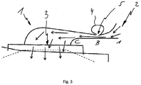
- the Venturi nozzle has a plurality of flow sections with different cross sections A, B, C, the cross sections A, C being larger than the smallest cross section B of the Venturi nozzle of the bend.
- the manifold 1 has a very flat shape and the area of the Venturi nozzle with the smallest cross-section B is formed substantially slit-shaped and extends over the entire width B of the manifold 1.
- the small cross-section B of the manifold 1 is achieved in that its outer surfaces the substantially straight bottom surface extends from both sides.
- a feed line 4 is formed, which extends substantially tubular over the entire width b of the manifold 1.
- the supply line 4 extends in the height direction approximately as far as the other components of the manifold 1 in order to achieve a compact unit as possible.
- an opening gap 5 is provided in the region of the smallest cross section B, which preferably extends over the entire width b of the Venturi nozzle.
- the feed line 4 is arranged on the manifold 1 such that the opening gap 5 extends exactly along the position of the smallest cross section.
- the opening gap 5 has a predetermined distance to the position of the smallest cross section, but this distance should not exceed 10% of the total length l of the manifold 1.
- Fig. 2 is the device 1 according to the invention in a plan view, mounted on a fan, shown in cross section.
- the manifold 1 extends over the length l and has the width b.
- the air flows over the entire width b of the air inlet 2 into the manifold 1, and is accelerated to the region of the smallest cross-section B.
- the supply line 4 has a flange 6 to which a gas line can be fastened in order to mix in gas via the supply line 4 and the opening gap 5 of the intake air.
- the mixture outlet 3 is designed as a circular outlet opening, wherein a distance f between the edge of the outlet opening and the area of the smallest cross-section B substantially has the value of the diameter d of the outlet opening.
- the distance fauch can be made larger, but should never be greater than 1.5 times the value of the diameter d of the outlet opening.
- the width b of the manifold 1 is slightly larger than the diameter of the outlet opening d, wherein the difference between b and d can already be exhausted in the material thickness of the manifold 1 and thus b and d can also be chosen the same size.
- the invention is not limited in its execution to the embodiment shown above. Rather, a number of variants are conceivable, which are also within the scope of the invention. For example, it is possible to move the supply line in the direction of the intake or in the direction of the air inlet, as long as the desired admixture of the gas is still guaranteed. Furthermore, it would be possible to form the air inlet of the bend straight and provide only a deflection of the flow in the region of the mixture outlet. In addition to the use of an opening gap shown, it is also possible to provide a plurality of openings, which ensure a gas inlet into the flow within the manifold.
Landscapes
- Engineering & Computer Science (AREA)
- Chemical & Material Sciences (AREA)
- Combustion & Propulsion (AREA)
- Mechanical Engineering (AREA)
- General Engineering & Computer Science (AREA)
- Gas Burners (AREA)
- Jet Pumps And Other Pumps (AREA)
Description
- Die Erfindung betrifft eine Vorrichtung zur Anbringung an der Ansaugseite eines Gebläses, insbesondere eines Vormischgebläses, und umfasst einen Gaseintritt sowie einen Gasaustritt, wobei die Vorrichtung als Krümmer ausgebildet und in dem Krümmer eine Venturidüse integriert ist.
- Die Erfindung wird beispielhaft anhand eines Vormischgebläses beschrieben, umfasst werden jedoch ebenso Gebläse ohne Vormischfunktion. Bei Vormischgebläsen für Gasbrenner werden üblicherweise von einem Radialgebläse Luft und Brenngas angesaugt, in einem Gebläse vorgemischt und als brennfähige Mischung in den Brenner eingeblasen. Zur Regelung des Mischungsverhältnisses, d.h. der Anteile von Luft und Gas, werden Ventile eingesetzt, die entweder elektronisch oder pneumatisch regelbar sind. Bei einer pneumatischen Regelung wird das Gasventil über einen pneumatischen Unterdruck angesteuert und das Gas direkt in die Strömung der angesaugten Luft zugemischt. Abhängig von der pro Zeit angesaugten Luftmenge ergibt sich eine entsprechende zugemischte Gasmenge. Dabei ist bekannt, den Unterdruck mittels einer auf der Ansaugseite des Vormischgebläses angeordneten Venturidüse zu erzielen, bei der mittels lokaler Strömungsquerschnittsverringerung eine lokal höhere Strömungsgeschwindigkeit und damit ein Unterdruck erzielt wird (Bernoulli-Gleichung).
- Venturidüsen müssen verglichen mit ihrem Durchmesser über eine gewisse Länge verfügen, um den notwendigen Unterdruck zu erzeugen. Das Verhältnis zwischen Länge und Durchmesser wird als Aspektverhältnis bezeichnet. Bei Vormischgebläsen beträgt das Aspektverhältnis üblicherweise 1:5 bezogen auf den geringsten oder ca. 1:3 bezogen auf den größten Querschnitt der Venturidüse. Die Vorrichtungen zur Vormischung werden an die seitliche Ansaugöffnung des Gebläses montiert, wodurch sich bei bekannten Aufbauten eine erhebliche Baugröße in allen Richtungen ergab, die unerwünscht ist.
- Als druckschriftlicher Stand der Technik ist aus der
EP 0 896 191 A2 ist eine Drallerzeuger mit darauf einteilig ausgebildeter Leiteinrichtung bekannt. DieDE 102 02 702 A1 und dieEP 2 163 820 A1 sind weitere Druckschriften aus dem vorliegenden technischen Gebiet. - Es ist die Aufgabe der Erfindung, eine Vorrichtung bereitzustellen, die die bekannten Vorteile einer pneumatischen Gemischbildung mittels Venturidüse derart verbessert, dass der benötigte Bauraum in Höhenrichtung möglichst gering ist.
- Diese Aufgabe wird mit dem Gegenstand des unabhängigen Anspruchs 1 gelöst.
- Es wird eine Vorrichtung für die Ansaugseite eines Vormischgebläses mit einem Luftbzw. Gaseintritt und einem Gas- bzw. Gemischaustritt bereitgestellt, wobei die Vorrichtung als Krümmer ausgebildet und in den Krümmer eine Venturidüse integriert ist. Als Krümmer wird eine Bauteilsform verstanden, die die dem nachgeschalteten Gebläse zugeführte Strömung, vorzugsweise in radialer Richtung des Gebläserades, umlenkt. Durch eine derartige Umlenkung kann die Erstreckung in Höhenrichtung, d.h. in axialer Richtung zu dem Gebläserad, sehr gering gehalten und somit eine kompakte und matertalsparende Baueinheit erzielt werden.
- Bei der Durchströmung einer Venturidüse wird das Fluid bis zum engsten Querschnitt beschleunigt und anschließend verzögert. Bei der Verzögerung der Strömung steigt der Druck, wobei es zu einer Ablösung der Strömung am Rand, der sogenannten Grenzschichtablösung kommen kann, die zu Verlusten führt. Dem Fachmann ist deshalb bekannt, dass sich die Venturidüse ausgehend von dem engsten Querschnitt nicht zu stark öffnen darf, wobei als üblicher Wert ein Öffnungswinkel von 10° nicht überschritten werden sollte. Die Strömung ist jedoch selbst bei optimalen Anliegen über die gesamte Länge der Venturidüse verlustbehaftet.
- Auch bei der Verwendung von Krümmern ist bekannt, dass die Umlenkung der Strömung innerhalb des Krümmers, insbesondere wenn es zu einer Ablösung der Strömung kommt, verlustbehaftet ist. Es ist deshalb notwendig, auch den Krümmer so auszulegen, dass möglichst geringe Verluste auftreten. Als bekanntes Mittel zur Reduzierung der Gefahr der Ablösung der Strömung werden für die Umlenkung relativ große Radien verwendet, wodurch jedoch die Abmaße des Krümmers erheblich vergrößert werden.
- Durch die Integration der Venturidüse in den Krümmer werden sowohl die Verluste der Venturidüse als auch des Krümmers räumlich zusammengefasst und der sich daraus ergebende Gesamtverlust verringert.
- Erfindungsgemäß ist die Venturidüse des Krümmers im Bereich des geringsten Querschnitts im wesentlichen schlitzförmig ausgebildet, wobei sich der Schlitz im wesentlichen über die gesamte Breite der Venturidüse erstrecken kann. Durch die schlitzförmige Ausbildung des Bereichs mit geringem Querschnitt der Venturidüse ist über die Breite des Krümmers eine im wesentlichen ablösefreie Strömung gewährleistet, so dass der Gesamtverlust äußerst gering ist.
- In einer günstigen Ausführung kann eine Zuleitung einteilig mit der Vorrichtung bzw. dem Krümmer ausgebildet sein, wobei die Zuleitung im wesentlichen rohrförmig ist und sich zumindest über die gesamte Breite des Krümmers erstreckt. Zwischen der Zuleitung und dem Bereich des geringsten Querschnitts der Venturidüse ist vorzugsweise ein Öffnungsspalt oder es sind mit entsprechendem Querschnitt ausgebildete Durchgangslöcher vorgesehen, um ein effektives Beimischen des über die Zuleitung zugeführten Gases zu ermöglichen. Die Gasverteilung innerhalb der Zuleitung ist möglichst homogen, so dass über den Öffnungsspalt eine möglichst konstante Gasabgabe gewährleistet ist. Der Öffnungsspalt erstreckt sich mindestens über die halbe Breite der Venturidüse, vorzugsweise jedoch im wesentlichen über die gesamte Breite, um einen möglichst hohen Grad an Beimischung zu gewährleisten. Bei bestimmten Bauformen des Krümmers kann es günstig sein, dass der Öffnungsspalt von der Position des geringsten Querschnitts der Venturidüse am Krümmer beabstandet ist. Ein derartiger Abstand sollte jedoch höchstens 10% der Gesamtlänge der Vorrichtung bzw. des Krümmers nicht überschreiten, um eine effiziente Nutzung des Venturieffekts zu gewährleisten.
- Bei der erfindungsgemäßen Vorrichtung ist von Vorteil, dass von dem Lufteintritt zu dem Gemischaustritt eine Umlenkung der Strömung von vorzugsweise 30° erfolgen kann. Anwendungsabhängig kann aber auch eine Umlenkung zwischen 30° und sogar bis 180° erfolgen. Dies wird durch die Ausbildung der Vorrichtung als Krümmer ermöglicht, wobei die angesaugte Luft nicht wie beim Stand der Technik axial zum Gebläserad, sondern im wesentlichen aus radialer Richtung angesaugt und erst bei der Ansaugöffnung des Gebläsegehäuses in eine axiale Strömung umgelenkt wird. Zur möglichst verlustfreien Strömung innerhalb der Vorrichtung bzw. des Krümmers kann vorgesehen sein, dass die Strömung bereits von dem Lufteintritt zu dem Bereich des geringsten Querschnitts um mindestens 15°, vorzugsweise in eine Strömung parallel zu der Gebläseaußenwand, umgelenkt wird.
- Bezüglich der geometrischen Form der Vorrichtung ist bevorzugt, dass der Querschnitt im Bereich des Lufteinlasses zu dem Querschnitt im engsten Bereich der Venturidüse ein Verhältnis von Höhe zu Breite zwischen 1:1,5 und 1:2, vorzugsweise 1:1,7 aufweisen. Ferner ist günstig, wenn der Gemischaustritt als eine im wesentlichen runde Auslassöffnung ausgebildet ist, und ein Abstand zwischen dem Rand dieser Auslassöffnung und dem Bereich des geringsten Querschnitts des Krümmers höchsten den 1,5-fachen Wert des Durchmessers der Auslassöffnung aufweist. Bei Verwendung des Laufrads als Bezugsgröße sollte der Abstand zwischen dem Mittelpunkt der Auslassöffnung und dem Bereich des geringsten Querschnitts (B) höchstens den 1,5 fachen Wert des Radius des Laufrades des verwendeten Gebläses sein. Größere Abstände führen zu einer verlustbehafteteren Strömung. Eine effiziente Nutzung des Bauraums ist vor allem dann gegeben, wenn das Venturi den Laufradaussendurchmesser des jeweils eingesetzten Gebläserads um weniger als die 20% überragt.
- Ferner ist bevorzugt, dass die Breite der Venturidüse im Ansaugbereich im wesentlichen oder genau dem Durchmesser der Auslassöffnung entspricht. Dadurch ist gewährleistet, dass die Strömung über die gesamte Länge der Vorrichtung bzw. des Krümmers und über dessen gesamte Breite verläuft, ohne dass verlusterzeugende Beschränkungen oder Einschnürungen vorgesehen wären.
- Zur optimalen Gaszuführung kann an der Zuleitung ein Flansch vorgesehen sein, an dem eine Gasleitung befestigbar ist. Die Zuleitung erstreckt sich vorzugsweise über die gesamte Breite des Krümmers, um somit eine Zumischung des Gases zu der durch die Venturidüse strömenden Luft über die gesamte Breite des Krümmers zu gewährleisten. Auf diese Weise kann dem Gebläse eine möglichst homogene Mischung aus Luft und Gas über die Ansaugöffnung zugeführt werden.
- Weitere Merkmale, Vorteile und Ausführungsformen der Erfindung sind Gegenstand der nachfolgenden Beschreibung und der schematischen Darstellung von Ausführungsbeispielen.
- Es zeigen:
- Fig. 1
- eine seitliche Schnittansicht einer erfindungsgemäßen Vorrichtung auf einem Gebläsegehäuse,
- Fig. 2
- eine Draufsicht der erfindungsgemäßen Vorrichtung auf einem Gebläse,
- Fig. 3
- eine vergrößerte Ansicht der Vorrichtung aus
Fig. 1 . -
Fig. 1 zeigt die als Krümmer ausgebildete Vorrichtung 1, montiert auf einem Gebläsegehäuse, in dem ein Gebläserad angeordnet ist. Die Vorrichtung 1 ist im wesentlichen doppelt so breit wie hoch, wobei die Höhenrichtung eine Axialrichtung des Gebläserades und die Breitenrichtung eine radiale Richtung des Gebläserades bilden. In dem inFig. 3 vergrößert dargestellten Krümmer 1 ist eine Venturidüse integriert, die zu der Ansaugöffnung des Gebläses und dem Gemischaustritt 3 des Krümmers beabstandet ist. Die Venturidüse weist mehrere Strömungsabschnitte mit unterschiedlichen Querschnitten A, B, C auf, wobei die Querschnitte A, C größer sind als der geringste Querschnitt B der Venturidüse des Krümmers. Der Krümmer 1 weist eine sehr flache Form auf und der Bereich der Venturidüse mit geringstem Querschnitt B ist im wesentlichen schlitzförmig ausgebildet und erstreckt sich über die gesamte Breite B des Krümmers 1. Der geringe Querschnitt B des Krümmers 1 wird dadurch erzielt, dass seine Außenflächen auf die im wesentlichen gerade Bodenfläche von beiden Seiten hin verläuft. - An dem Krümmer 1 ist im Bereich des geringsten Querschnitts B einteilig eine Zuleitung 4 ausgebildet, die sich im wesentlichen rohrförmig über die gesamte Breite b des Krümmers 1 erstreckt. Die Zuleitung 4 erstreckt sich in die Höhenrichtung in etwa soweit wie die übrigen Bauteile des Krümmers 1, um eine möglichst kompakte Baueinheit zu erzielen. Zwischen der Zuleitung 4 und dem Strömungskanal des Krümmers 1 ist im Bereich des geringsten Querschnitts B ein Öffnungsspalt 5 vorgesehen, der sich vorzugsweise über die gesamte Breite b der Venturidüse erstreckt. Bei der gezeigten Ausführung ist die Zuleitung 4 derart am Krümmer 1 angeordnet, dass sich der Öffnungsspalt 5 exakt entlang der Position des geringsten Querschnitts erstreckt. Bei alternativen Ausführungen kann vorgesehen sein, dass der Öffnungsspalt 5 einen vorbestimmten Abstand zu der Position des geringsten Querschnitts aufweist, dieser Abstand sollte jedoch 10% der Gesamtlänge I des Krümmers 1 nicht überschreiten. Mit dem erfindungsgemäßen Krümmer 1 wird die Strömung von dem Lufteintritt 2 zu dem Gemischaustritt 3 um ca. 120° umgelenkt, wobei eine erste Umlenkung von dem Lufteintritt 2 zu der Venturidüse hin und eine zweite Umlenkung im Bereich der Auslassöffnung 3 des Krümmers 1 erfolgt.
- In
Fig. 2 ist die erfindungsgemäße Vorrichtung 1 in einer Draufsicht, montiert auf ein Gebläse, im Querschnitt gezeigt. Der Krümmer 1 erstreckt sich über die Länge l und weist die Breite b auf. Die Luft strömt über die gesamte Breite b des Lufteintritts 2 in den Krümmer 1 hinein, und wird bis zum Bereich des geringsten Querschnitts B beschleunigt. Die Zuleitung 4 weist einen Flansch 6 auf, an dem eine Gasleitung befestigbar ist, um über die Zuleitung 4 und dem Öffnungsspalt 5 der angesaugten Luft Gas beizumischen. Der Gemischaustritt 3 ist als runde Auslassöffnung ausgebildet, wobei ein Abstand f zwischen dem Rand der Auslassöffnung und dem Bereich des geringsten Querschnitts B im wesentlichen den Wert des Durchmessers d der Auslassöffnung aufweist. In einer alternativen Ausführung kann der Abstand fauch größer gewählt werden, sollte jedoch nie größer als der 1,5-fache Wert des Durchmessers d der Auslassöffnung sein. Die Breite b des Krümmers 1 ist geringfügig größer als der Durchmesser der Auslassöffnung d, wobei der Unterschied zwischen b und d sich bereits in der Materialdicke des Krümmers 1 erschöpfen kann und somit b und d auch gleich groß gewählt werden können. - Die Erfindung beschränkt sich in ihrer Ausführung nicht auf das vorstehend gezeigte Ausführungsbeispiel. Vielmehr ist eine Anzahl von Varianten denkbar, die ebenfalls im Schutzbereich der Erfindung liegen. So ist beispielsweise möglich, die Zuleitung in Richtung der Ansaugöffnung oder in Richtung des Lufteintritts zu verschieben, solange die gewünschte Beimischung des Gases noch gewährleistet ist. Ferner wäre es möglich, den Lufteintritt des Krümmers gerade auszubilden und lediglich eine Umlenkung der Strömung im Bereich des Gemischaustritts vorzusehen. Neben der gezeigten Verwendung eines Öffnungsspalts ist es auch möglich, mehrere Öffnungen vorzusehen, die einen Gaseintritt in die Strömung innerhalb des Krümmers gewährleisten.
Claims (13)
- Vorrichtung (1) für die Ansaugseite eines Gebläses mit mindestens einem Gaseintritt (2) und einem Gasaustritt (3), wobei die Vorrichtung (1) als Krümmer ausgebildet und in den Krümmer eine Venturidüse integriert ist, wobei die Venturidüse mehrere Strömungsabschnitte mit unterschiedlichen Querschnitte (A, B, C) aufweist,
dadurch gekennzeichnet, dass die Venturidüse des Krümmers im Beireich des geringsten Querschnitts (B) im Wesentlichen schlitzförmig ausgebildet ist. - Vorrichtung nach mindestens einem der vorigen Ansprüche, dadurch gekennzeichnet, dass sich der Schlitz im Wesentlichen über die gesamte Breite (b) der Venturidüse des Krümmers erstreckt.
- Vorrichtung nach mindestens einem der vorigen Ansprüche, dadurch gekennzeichnet, dass eine Zuleitung (4) einteilig mit der Vorrichtung (1) ausgebildet ist.
- Vorrichtung nach dem vorigen Anspruch, dadurch gekennzeichnet, dass zwischen der Zuleitung (4) und dem Bereich des geringsten Querschnitts (B) der Venturidüse ein Öffnungsspalt (5) vorgesehen ist.
- Vorrichtung nach dem vorigen Anspruch, dadurch gekennzeichnet, dass sich der Öffnungsspalt (5) mindestens über die halbe Breite (b) der Venturidüse erstreckt.
- Vorrichtung nach einem der Ansprüche 4 oder 5 dadurch gekennzeichnet, dass der Abstand des Öffnungsspalts (5) von der Position des geringsten Querschnitts (B) höchstens 10% der Gesamtlänge (l) der Vorrichtung ist.
- Vorrichtung nach mindestens einem der vorigen Ansprüche, dadurch gekennzeichnet, dass von dem Gaseintritt (2) zu dem Gemischaustritt (3) eine Umlenkung der Strömung von mindestens 30 GRAD erfolgt.
- Vorrichtung nach mindestens einem der vorigen Ansprüche, dadurch gekennzeichnet, dass von dem Gaseintritt (2) zu dem Bereich des geringsten Querschnitts (B) eine Umlenkung der Strömung von mindestens 15 GRAD erfolgt.
- Vorrichtung nach mindestens einem der vorigen Ansprüche, dadurch gekennzeichnet, dass die Querschnitte (A, B) ein Verhältnis von Höhe zu Breite (b) zwischen 1 : 1,5 und 1 : 2 aufweisen.
- Vorrichtung nach mindestens einem der vorigen Ansprüche dadurch gekennzeichnet, dass der Gasaustritt (3) als eine im Wesentlichen runde Auslassöffnung gebildet ist und ein Abstand (f) zwischen dem Rand der Auslassöffnung und dem Bereich des geringsten Querschnitts (B) höchstens den 1,5 fachen Wert des Durchmessers (d) der Auslassöffnung aufweist.
- Vorrichtung nach dem vorigen Anspruch, dadurch gekennzeichnet, dass die Breite (b) der Venturidüse im Ansaugbereich im Wesentlichen dem Durchmesser (d) der Auslassöffnung entspricht.
- Vorrichtung nach einem der Ansprüche 3 bis 6, dadurch gekennzeichnet, dass die Zuleitung (4) einen Flansch (6) aufweist, an dem eine Gasleitung anschließbar ist.
- Vorrichtung nach einem der Ansprüche 3 bis 6, dadurch gekennzeichnet, dass sich die Zuleitung über die gesamte Breite (b) der Venturidüse des Krümmers erstreckt
Applications Claiming Priority (2)
| Application Number | Priority Date | Filing Date | Title |
|---|---|---|---|
| DE102009050562A DE102009050562A1 (de) | 2009-10-23 | 2009-10-23 | Vorrichtung für die Ansaugseite eines Gebläses |
| PCT/EP2010/061001 WO2011047895A1 (de) | 2009-10-23 | 2010-07-29 | Vorrichtung für die ansaugseite eines gebläses |
Publications (2)
| Publication Number | Publication Date |
|---|---|
| EP2491308A1 EP2491308A1 (de) | 2012-08-29 |
| EP2491308B1 true EP2491308B1 (de) | 2017-07-19 |
Family
ID=43066779
Family Applications (1)
| Application Number | Title | Priority Date | Filing Date |
|---|---|---|---|
| EP10740592.0A Not-in-force EP2491308B1 (de) | 2009-10-23 | 2010-07-29 | Vorrichtung für die ansaugseite eines gebläses |
Country Status (4)
| Country | Link |
|---|---|
| EP (1) | EP2491308B1 (de) |
| DE (1) | DE102009050562A1 (de) |
| NL (1) | NL1038321C2 (de) |
| WO (1) | WO2011047895A1 (de) |
Families Citing this family (20)
| Publication number | Priority date | Publication date | Assignee | Title |
|---|---|---|---|---|
| US8899264B2 (en) | 2011-12-15 | 2014-12-02 | Honeywell International Inc. | Gas valve with electronic proof of closure system |
| US8905063B2 (en) | 2011-12-15 | 2014-12-09 | Honeywell International Inc. | Gas valve with fuel rate monitor |
| US9835265B2 (en) | 2011-12-15 | 2017-12-05 | Honeywell International Inc. | Valve with actuator diagnostics |
| US9074770B2 (en) | 2011-12-15 | 2015-07-07 | Honeywell International Inc. | Gas valve with electronic valve proving system |
| US9557059B2 (en) | 2011-12-15 | 2017-01-31 | Honeywell International Inc | Gas valve with communication link |
| US8839815B2 (en) | 2011-12-15 | 2014-09-23 | Honeywell International Inc. | Gas valve with electronic cycle counter |
| US9846440B2 (en) | 2011-12-15 | 2017-12-19 | Honeywell International Inc. | Valve controller configured to estimate fuel comsumption |
| US9851103B2 (en) | 2011-12-15 | 2017-12-26 | Honeywell International Inc. | Gas valve with overpressure diagnostics |
| US9995486B2 (en) | 2011-12-15 | 2018-06-12 | Honeywell International Inc. | Gas valve with high/low gas pressure detection |
| US8947242B2 (en) | 2011-12-15 | 2015-02-03 | Honeywell International Inc. | Gas valve with valve leakage test |
| US10422531B2 (en) | 2012-09-15 | 2019-09-24 | Honeywell International Inc. | System and approach for controlling a combustion chamber |
| US9234661B2 (en) | 2012-09-15 | 2016-01-12 | Honeywell International Inc. | Burner control system |
| EP2868970B1 (de) | 2013-10-29 | 2020-04-22 | Honeywell Technologies Sarl | Regelungsvorrichtung |
| US10024439B2 (en) | 2013-12-16 | 2018-07-17 | Honeywell International Inc. | Valve over-travel mechanism |
| US9841122B2 (en) | 2014-09-09 | 2017-12-12 | Honeywell International Inc. | Gas valve with electronic valve proving system |
| US9645584B2 (en) | 2014-09-17 | 2017-05-09 | Honeywell International Inc. | Gas valve with electronic health monitoring |
| US10503181B2 (en) | 2016-01-13 | 2019-12-10 | Honeywell International Inc. | Pressure regulator |
| US10564062B2 (en) | 2016-10-19 | 2020-02-18 | Honeywell International Inc. | Human-machine interface for gas valve |
| US11073281B2 (en) | 2017-12-29 | 2021-07-27 | Honeywell International Inc. | Closed-loop programming and control of a combustion appliance |
| US10697815B2 (en) | 2018-06-09 | 2020-06-30 | Honeywell International Inc. | System and methods for mitigating condensation in a sensor module |
Family Cites Families (5)
| Publication number | Priority date | Publication date | Assignee | Title |
|---|---|---|---|---|
| DE19540772A1 (de) * | 1995-11-02 | 1997-05-07 | Buderus Heiztechnik Gmbh | Atmosphärischer Gasbrenner |
| EP0834695B1 (de) * | 1996-10-03 | 1999-09-01 | Siabs Industry S.R.L. | Vorrichtung zum Zuführen eines Gas/Luft-Gemisches zu einem Brenner, insbesondere für Heizungsanlagen |
| DE19733769C2 (de) * | 1997-08-05 | 2003-05-22 | Dungs Karl Gmbh & Co | Brenngas-Einleitungsvorrichtung für einen Gas-Vormischbrenner |
| DE10202702B4 (de) * | 2001-01-24 | 2013-01-10 | IfTA Ingenieurbüro für Thermoakustik GmbH | Heizgerät mit einem Gehäuse |
| ES2603421T3 (es) * | 2008-09-16 | 2017-02-27 | Siemens Aktiengesellschaft | Quemador de gas |
-
2009
- 2009-10-23 DE DE102009050562A patent/DE102009050562A1/de not_active Withdrawn
-
2010
- 2010-07-29 EP EP10740592.0A patent/EP2491308B1/de not_active Not-in-force
- 2010-07-29 WO PCT/EP2010/061001 patent/WO2011047895A1/de not_active Ceased
- 2010-10-21 NL NL1038321A patent/NL1038321C2/nl not_active IP Right Cessation
Non-Patent Citations (1)
| Title |
|---|
| None * |
Also Published As
| Publication number | Publication date |
|---|---|
| DE102009050562A1 (de) | 2011-04-28 |
| NL1038321A (nl) | 2011-04-26 |
| NL1038321C2 (nl) | 2012-03-20 |
| WO2011047895A1 (de) | 2011-04-28 |
| EP2491308A1 (de) | 2012-08-29 |
Similar Documents
| Publication | Publication Date | Title |
|---|---|---|
| EP2491308A1 (de) | Vorrichtung für die ansaugseite eines gebläses | |
| DE2832708C2 (de) | ||
| DE102013004076B4 (de) | Strahlregler mit Prallfläche und Ringwandung | |
| EP2232147B1 (de) | Brenner und verfahren zur verringerung von selbstinduzierten flammenschwingungen | |
| EP3101184B1 (de) | Sanitäre einsetzeinheit | |
| EP0896191A2 (de) | Brenngas-Einleitungsvorrichtung für einen Gas-Vormischbrenner | |
| DE202013002282U1 (de) | Strahlregler mit Prallfläche und Ringwandung | |
| AT504179A2 (de) | Brennkraftmaschine mit einem einlasssystem | |
| DE102016113588A1 (de) | Gas-Luft-Mischvorrichtung | |
| EP3274569A1 (de) | Mischvorrichtung | |
| EP2578319B1 (de) | Brausekopf | |
| DE69603715T2 (de) | Venturi mischvorrichtung | |
| WO2008019969A1 (de) | Verbrennungssystem insbesondere für eine gasturbine | |
| DE69803668T2 (de) | Brenner mit venturirohr und strömungsverteiler | |
| DE102004015829B4 (de) | Ansaugstutzen | |
| DE112017004546T5 (de) | Drosselkörper mit fluiddurchflusssteuerung | |
| DE102013002235B4 (de) | Luftansaugvorrichtung für eine Sanitärbrause | |
| EP3462088B1 (de) | Brennstoff-luft-mischeinrichtung und ein heizgerät | |
| DE102010009051A1 (de) | Brennstoffzuführungseinrichtung | |
| DE20304660U1 (de) | Sanitäre Einsetzeinheit | |
| DE102024208763A1 (de) | Fluid-Mischeinheit mit einem Venturi-Mischer, der einen schlitzförmigen Fluid-Mischabschnitt aufweist | |
| DE102010063986B4 (de) | Düsenbaugruppe für ein Einspritzventil und Einspritzventil | |
| EP1998113A2 (de) | Gasbrenner | |
| DE102021203755A1 (de) | Strahlpumpe, insbesondere Strahlpumpe für eine Brennstoffzellenanwendung | |
| EP4685300A1 (de) | Sanitäres einsetzteil |
Legal Events
| Date | Code | Title | Description |
|---|---|---|---|
| PUAI | Public reference made under article 153(3) epc to a published international application that has entered the european phase |
Free format text: ORIGINAL CODE: 0009012 |
|
| 17P | Request for examination filed |
Effective date: 20120417 |
|
| AK | Designated contracting states |
Kind code of ref document: A1 Designated state(s): AL AT BE BG CH CY CZ DE DK EE ES FI FR GB GR HR HU IE IS IT LI LT LU LV MC MK MT NL NO PL PT RO SE SI SK SM TR |
|
| RIN1 | Information on inventor provided before grant (corrected) |
Inventor name: METZ, TOBIAS Inventor name: KEBER, ROLAND |
|
| RIN1 | Information on inventor provided before grant (corrected) |
Inventor name: KEBER, ROLAND Inventor name: METZ, TOBIAS |
|
| DAX | Request for extension of the european patent (deleted) | ||
| 17Q | First examination report despatched |
Effective date: 20151102 |
|
| GRAP | Despatch of communication of intention to grant a patent |
Free format text: ORIGINAL CODE: EPIDOSNIGR1 |
|
| INTG | Intention to grant announced |
Effective date: 20170302 |
|
| GRAS | Grant fee paid |
Free format text: ORIGINAL CODE: EPIDOSNIGR3 |
|
| GRAA | (expected) grant |
Free format text: ORIGINAL CODE: 0009210 |
|
| AK | Designated contracting states |
Kind code of ref document: B1 Designated state(s): AL AT BE BG CH CY CZ DE DK EE ES FI FR GB GR HR HU IE IS IT LI LT LU LV MC MK MT NL NO PL PT RO SE SI SK SM TR |
|
| REG | Reference to a national code |
Ref country code: GB Ref legal event code: FG4D Free format text: NOT ENGLISH |
|
| REG | Reference to a national code |
Ref country code: FR Ref legal event code: PLFP Year of fee payment: 8 |
|
| REG | Reference to a national code |
Ref country code: CH Ref legal event code: EP |
|
| REG | Reference to a national code |
Ref country code: IE Ref legal event code: FG4D Free format text: LANGUAGE OF EP DOCUMENT: GERMAN |
|
| REG | Reference to a national code |
Ref country code: AT Ref legal event code: REF Ref document number: 910754 Country of ref document: AT Kind code of ref document: T Effective date: 20170815 |
|
| REG | Reference to a national code |
Ref country code: DE Ref legal event code: R096 Ref document number: 502010013886 Country of ref document: DE |
|
| REG | Reference to a national code |
Ref country code: NL Ref legal event code: MP Effective date: 20170719 |
|
| REG | Reference to a national code |
Ref country code: LT Ref legal event code: MG4D |
|
| PG25 | Lapsed in a contracting state [announced via postgrant information from national office to epo] |
Ref country code: SE Free format text: LAPSE BECAUSE OF FAILURE TO SUBMIT A TRANSLATION OF THE DESCRIPTION OR TO PAY THE FEE WITHIN THE PRESCRIBED TIME-LIMIT Effective date: 20170719 Ref country code: NO Free format text: LAPSE BECAUSE OF FAILURE TO SUBMIT A TRANSLATION OF THE DESCRIPTION OR TO PAY THE FEE WITHIN THE PRESCRIBED TIME-LIMIT Effective date: 20171019 Ref country code: FI Free format text: LAPSE BECAUSE OF FAILURE TO SUBMIT A TRANSLATION OF THE DESCRIPTION OR TO PAY THE FEE WITHIN THE PRESCRIBED TIME-LIMIT Effective date: 20170719 Ref country code: NL Free format text: LAPSE BECAUSE OF FAILURE TO SUBMIT A TRANSLATION OF THE DESCRIPTION OR TO PAY THE FEE WITHIN THE PRESCRIBED TIME-LIMIT Effective date: 20170719 Ref country code: LT Free format text: LAPSE BECAUSE OF FAILURE TO SUBMIT A TRANSLATION OF THE DESCRIPTION OR TO PAY THE FEE WITHIN THE PRESCRIBED TIME-LIMIT Effective date: 20170719 Ref country code: HR Free format text: LAPSE BECAUSE OF FAILURE TO SUBMIT A TRANSLATION OF THE DESCRIPTION OR TO PAY THE FEE WITHIN THE PRESCRIBED TIME-LIMIT Effective date: 20170719 |
|
| PG25 | Lapsed in a contracting state [announced via postgrant information from national office to epo] |
Ref country code: PL Free format text: LAPSE BECAUSE OF FAILURE TO SUBMIT A TRANSLATION OF THE DESCRIPTION OR TO PAY THE FEE WITHIN THE PRESCRIBED TIME-LIMIT Effective date: 20170719 Ref country code: GR Free format text: LAPSE BECAUSE OF FAILURE TO SUBMIT A TRANSLATION OF THE DESCRIPTION OR TO PAY THE FEE WITHIN THE PRESCRIBED TIME-LIMIT Effective date: 20171020 Ref country code: ES Free format text: LAPSE BECAUSE OF FAILURE TO SUBMIT A TRANSLATION OF THE DESCRIPTION OR TO PAY THE FEE WITHIN THE PRESCRIBED TIME-LIMIT Effective date: 20170719 Ref country code: IS Free format text: LAPSE BECAUSE OF FAILURE TO SUBMIT A TRANSLATION OF THE DESCRIPTION OR TO PAY THE FEE WITHIN THE PRESCRIBED TIME-LIMIT Effective date: 20171119 Ref country code: BG Free format text: LAPSE BECAUSE OF FAILURE TO SUBMIT A TRANSLATION OF THE DESCRIPTION OR TO PAY THE FEE WITHIN THE PRESCRIBED TIME-LIMIT Effective date: 20171019 Ref country code: LV Free format text: LAPSE BECAUSE OF FAILURE TO SUBMIT A TRANSLATION OF THE DESCRIPTION OR TO PAY THE FEE WITHIN THE PRESCRIBED TIME-LIMIT Effective date: 20170719 |
|
| REG | Reference to a national code |
Ref country code: CH Ref legal event code: PL |
|
| REG | Reference to a national code |
Ref country code: DE Ref legal event code: R097 Ref document number: 502010013886 Country of ref document: DE |
|
| PG25 | Lapsed in a contracting state [announced via postgrant information from national office to epo] |
Ref country code: CZ Free format text: LAPSE BECAUSE OF FAILURE TO SUBMIT A TRANSLATION OF THE DESCRIPTION OR TO PAY THE FEE WITHIN THE PRESCRIBED TIME-LIMIT Effective date: 20170719 Ref country code: DK Free format text: LAPSE BECAUSE OF FAILURE TO SUBMIT A TRANSLATION OF THE DESCRIPTION OR TO PAY THE FEE WITHIN THE PRESCRIBED TIME-LIMIT Effective date: 20170719 Ref country code: CH Free format text: LAPSE BECAUSE OF NON-PAYMENT OF DUE FEES Effective date: 20170731 Ref country code: MC Free format text: LAPSE BECAUSE OF FAILURE TO SUBMIT A TRANSLATION OF THE DESCRIPTION OR TO PAY THE FEE WITHIN THE PRESCRIBED TIME-LIMIT Effective date: 20170719 Ref country code: LI Free format text: LAPSE BECAUSE OF NON-PAYMENT OF DUE FEES Effective date: 20170731 Ref country code: RO Free format text: LAPSE BECAUSE OF FAILURE TO SUBMIT A TRANSLATION OF THE DESCRIPTION OR TO PAY THE FEE WITHIN THE PRESCRIBED TIME-LIMIT Effective date: 20170719 |
|
| REG | Reference to a national code |
Ref country code: IE Ref legal event code: MM4A |
|
| REG | Reference to a national code |
Ref country code: BE Ref legal event code: MM Effective date: 20170731 |
|
| PLBE | No opposition filed within time limit |
Free format text: ORIGINAL CODE: 0009261 |
|
| STAA | Information on the status of an ep patent application or granted ep patent |
Free format text: STATUS: NO OPPOSITION FILED WITHIN TIME LIMIT |
|
| PG25 | Lapsed in a contracting state [announced via postgrant information from national office to epo] |
Ref country code: SK Free format text: LAPSE BECAUSE OF FAILURE TO SUBMIT A TRANSLATION OF THE DESCRIPTION OR TO PAY THE FEE WITHIN THE PRESCRIBED TIME-LIMIT Effective date: 20170719 Ref country code: EE Free format text: LAPSE BECAUSE OF FAILURE TO SUBMIT A TRANSLATION OF THE DESCRIPTION OR TO PAY THE FEE WITHIN THE PRESCRIBED TIME-LIMIT Effective date: 20170719 Ref country code: SM Free format text: LAPSE BECAUSE OF FAILURE TO SUBMIT A TRANSLATION OF THE DESCRIPTION OR TO PAY THE FEE WITHIN THE PRESCRIBED TIME-LIMIT Effective date: 20170719 |
|
| 26N | No opposition filed |
Effective date: 20180420 |
|
| PG25 | Lapsed in a contracting state [announced via postgrant information from national office to epo] |
Ref country code: LU Free format text: LAPSE BECAUSE OF NON-PAYMENT OF DUE FEES Effective date: 20170729 |
|
| REG | Reference to a national code |
Ref country code: FR Ref legal event code: PLFP Year of fee payment: 9 |
|
| PG25 | Lapsed in a contracting state [announced via postgrant information from national office to epo] |
Ref country code: IE Free format text: LAPSE BECAUSE OF NON-PAYMENT OF DUE FEES Effective date: 20170729 |
|
| PG25 | Lapsed in a contracting state [announced via postgrant information from national office to epo] |
Ref country code: BE Free format text: LAPSE BECAUSE OF NON-PAYMENT OF DUE FEES Effective date: 20170731 Ref country code: SI Free format text: LAPSE BECAUSE OF FAILURE TO SUBMIT A TRANSLATION OF THE DESCRIPTION OR TO PAY THE FEE WITHIN THE PRESCRIBED TIME-LIMIT Effective date: 20170719 |
|
| REG | Reference to a national code |
Ref country code: AT Ref legal event code: MM01 Ref document number: 910754 Country of ref document: AT Kind code of ref document: T Effective date: 20170729 |
|
| PG25 | Lapsed in a contracting state [announced via postgrant information from national office to epo] |
Ref country code: MT Free format text: LAPSE BECAUSE OF FAILURE TO SUBMIT A TRANSLATION OF THE DESCRIPTION OR TO PAY THE FEE WITHIN THE PRESCRIBED TIME-LIMIT Effective date: 20170719 |
|
| PG25 | Lapsed in a contracting state [announced via postgrant information from national office to epo] |
Ref country code: AT Free format text: LAPSE BECAUSE OF NON-PAYMENT OF DUE FEES Effective date: 20170729 |
|
| PG25 | Lapsed in a contracting state [announced via postgrant information from national office to epo] |
Ref country code: HU Free format text: LAPSE BECAUSE OF FAILURE TO SUBMIT A TRANSLATION OF THE DESCRIPTION OR TO PAY THE FEE WITHIN THE PRESCRIBED TIME-LIMIT; INVALID AB INITIO Effective date: 20100729 |
|
| PG25 | Lapsed in a contracting state [announced via postgrant information from national office to epo] |
Ref country code: CY Free format text: LAPSE BECAUSE OF NON-PAYMENT OF DUE FEES Effective date: 20170719 |
|
| PG25 | Lapsed in a contracting state [announced via postgrant information from national office to epo] |
Ref country code: MK Free format text: LAPSE BECAUSE OF FAILURE TO SUBMIT A TRANSLATION OF THE DESCRIPTION OR TO PAY THE FEE WITHIN THE PRESCRIBED TIME-LIMIT Effective date: 20170719 |
|
| PG25 | Lapsed in a contracting state [announced via postgrant information from national office to epo] |
Ref country code: PT Free format text: LAPSE BECAUSE OF FAILURE TO SUBMIT A TRANSLATION OF THE DESCRIPTION OR TO PAY THE FEE WITHIN THE PRESCRIBED TIME-LIMIT Effective date: 20170719 |
|
| PG25 | Lapsed in a contracting state [announced via postgrant information from national office to epo] |
Ref country code: AL Free format text: LAPSE BECAUSE OF FAILURE TO SUBMIT A TRANSLATION OF THE DESCRIPTION OR TO PAY THE FEE WITHIN THE PRESCRIBED TIME-LIMIT Effective date: 20170719 |
|
| PGFP | Annual fee paid to national office [announced via postgrant information from national office to epo] |
Ref country code: FR Payment date: 20200727 Year of fee payment: 11 Ref country code: DE Payment date: 20200723 Year of fee payment: 11 Ref country code: TR Payment date: 20200724 Year of fee payment: 11 Ref country code: GB Payment date: 20200724 Year of fee payment: 11 |
|
| PGFP | Annual fee paid to national office [announced via postgrant information from national office to epo] |
Ref country code: IT Payment date: 20200731 Year of fee payment: 11 |
|
| REG | Reference to a national code |
Ref country code: DE Ref legal event code: R119 Ref document number: 502010013886 Country of ref document: DE |
|
| GBPC | Gb: european patent ceased through non-payment of renewal fee |
Effective date: 20210729 |
|
| PG25 | Lapsed in a contracting state [announced via postgrant information from national office to epo] |
Ref country code: GB Free format text: LAPSE BECAUSE OF NON-PAYMENT OF DUE FEES Effective date: 20210729 Ref country code: DE Free format text: LAPSE BECAUSE OF NON-PAYMENT OF DUE FEES Effective date: 20220201 |
|
| PG25 | Lapsed in a contracting state [announced via postgrant information from national office to epo] |
Ref country code: FR Free format text: LAPSE BECAUSE OF NON-PAYMENT OF DUE FEES Effective date: 20210731 |
|
| PG25 | Lapsed in a contracting state [announced via postgrant information from national office to epo] |
Ref country code: TR Free format text: LAPSE BECAUSE OF NON-PAYMENT OF DUE FEES Effective date: 20210729 |
|
| PG25 | Lapsed in a contracting state [announced via postgrant information from national office to epo] |
Ref country code: IT Free format text: LAPSE BECAUSE OF NON-PAYMENT OF DUE FEES Effective date: 20210729 |