EP2491264B1 - Extended plunge constant velocity joint - Google Patents
Extended plunge constant velocity joint Download PDFInfo
- Publication number
- EP2491264B1 EP2491264B1 EP09850663.7A EP09850663A EP2491264B1 EP 2491264 B1 EP2491264 B1 EP 2491264B1 EP 09850663 A EP09850663 A EP 09850663A EP 2491264 B1 EP2491264 B1 EP 2491264B1
- Authority
- EP
- European Patent Office
- Prior art keywords
- outer race
- piston
- constant velocity
- joint
- seal
- Prior art date
- Legal status (The legal status is an assumption and is not a legal conclusion. Google has not performed a legal analysis and makes no representation as to the accuracy of the status listed.)
- Active
Links
Images

Classifications
-
- F—MECHANICAL ENGINEERING; LIGHTING; HEATING; WEAPONS; BLASTING
- F16—ENGINEERING ELEMENTS AND UNITS; GENERAL MEASURES FOR PRODUCING AND MAINTAINING EFFECTIVE FUNCTIONING OF MACHINES OR INSTALLATIONS; THERMAL INSULATION IN GENERAL
- F16D—COUPLINGS FOR TRANSMITTING ROTATION; CLUTCHES; BRAKES
- F16D3/00—Yielding couplings, i.e. with means permitting movement between the connected parts during the drive
- F16D3/16—Universal joints in which flexibility is produced by means of pivots or sliding or rolling connecting parts
- F16D3/20—Universal joints in which flexibility is produced by means of pivots or sliding or rolling connecting parts one coupling part entering a sleeve of the other coupling part and connected thereto by sliding or rolling members
- F16D3/22—Universal joints in which flexibility is produced by means of pivots or sliding or rolling connecting parts one coupling part entering a sleeve of the other coupling part and connected thereto by sliding or rolling members the rolling members being balls, rollers, or the like, guided in grooves or sockets in both coupling parts
- F16D3/223—Universal joints in which flexibility is produced by means of pivots or sliding or rolling connecting parts one coupling part entering a sleeve of the other coupling part and connected thereto by sliding or rolling members the rolling members being balls, rollers, or the like, guided in grooves or sockets in both coupling parts the rolling members being guided in grooves in both coupling parts
- F16D2003/2232—Elements arranged in the hollow space between the end of the inner shaft and the outer joint member
-
- F—MECHANICAL ENGINEERING; LIGHTING; HEATING; WEAPONS; BLASTING
- F16—ENGINEERING ELEMENTS AND UNITS; GENERAL MEASURES FOR PRODUCING AND MAINTAINING EFFECTIVE FUNCTIONING OF MACHINES OR INSTALLATIONS; THERMAL INSULATION IN GENERAL
- F16D—COUPLINGS FOR TRANSMITTING ROTATION; CLUTCHES; BRAKES
- F16D2300/00—Special features for couplings or clutches
- F16D2300/06—Lubrication details not provided for in group F16D13/74
Definitions
- the present invention generally relates to constant velocity joints and specifically to an outer race assembly having a piston.
- US 2,284,199 discloses a torque transmitting slip joint of the type employed in motor vehicles to operatively connect the power plant to the road engaging driving wheels.
- the slip joint comprises an outer member with grooves extending longitudinally.
- a piston is secured to a rear end of a shaft beyond torque transmitting rollers and is provided with radially outwardly extending projections having side walls slidably engaging the walls of the grooves of the outer member.
- the piston has openings establishing communication between the spaces or chambers at opposite sides of the piston.
- US 1,620,285 discloses a flexible coupling adapted for use with high speed shafts.
- the working connection is provided by roller bearings, held against rotary movement in relation to sleeves.
- the balls are permitted axial movement in relation to one of said sleeves, along arcuately cross sectioned channels.
- a packaging ring is adapted closely to engage a cylindrical bearing surface of the sleeve.
- US 2008/0234057 discloses a slidable or plunging constant velocity joint.
- Constant velocity joints and other rotational joints are common components in automotive vehicles. Typically, constant velocity joints are used where a transmission of constant velocity rotating motion is required.
- the common types of constant velocity joints are plunging tripod, a fixed tripod, a plunging ball joint and a fixed ball joint. These types of joints are currently used in front wheel drive vehicles, rear wheel drive vehicles and on propeller shafts found in rear wheel drive, all wheel drive, and four wheel drive vehicles.
- the constant velocity joints are generally grease lubricated for life and sealed by a sealing boot when used on driveshafts or half shafts. Therefore, constant velocity joints are sealed in order to retain grease inside the joint and keep contaminants, such as dirt and water, out of the joint.
- the constant velocity joint is usually enclosed at the opened end of an outer race by a sealing boot made of a rubber, thermoplastic, or silicone type material.
- the opposite end of the outer race generally is enclosed by a dome or cap, known as a grease cap in the case of a disk type joint.
- a mono block or integral stem and race design style joint is sealed by the internal geometry of the outer race. This sealing and protection of the constant velocity joint is necessary because contamination of the inner chamber of the joint generally will cause internal damage to the joint.
- a main function of the constant velocity joint is the transmission of rotational forces and torque.
- a plunging joint will transmit rotational velocity while permitting relative axial displacement within the joint.
- a tripod joint operates as a plunging constant velocity joint while providing some degree of axial articulation.
- bolted joint designs are used to assemble a joint to a propshaft or halfshaft within the automotive vehicle. These propshaft and halfshaft assemblies are typically assembled prior to installation within a driveline of a vehicle.
- an inner rotating component When a joint is installed within a vehicle, an inner rotating component is generally plunged further into the joint in order to fit between vehicle components, e.g., a propshaft and differential. Accordingly, some extra amount of plunge capability beyond that which is necessary during ordinary operation of the vehicle must necessarily be designed into the joint. However, as the amount of lubricant required for the joint is generally dictated in part by the surface area presented by an outer rotating member within the sealed portion of the joint, the provision of this extra plunge capability requires additional lubricant within the joint, increasing costs and failure modes during operation.
- a constant velocity joint may generally include the components of an outer race assembly, including an outer race defining a plurality of tracks, a piston selectively moveable along the tracks of the outer race, and a seal disposed about the piston and abutting the outer race about substantially an entire perimeter of the piston. The seal thereby generally seals an interface between the piston and the outer race.
- the constant velocity joint may further include an inner rotational member coupled for rotation with the outer race and configured to translate axially with respect to the outer race along the plurality of tracks.
- a boot assembly may be selectively coupled to both the inner rotational member and the outer race, thereby sealing at least part of the inner rotational member to the outer race.
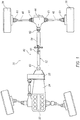
- the driveline 20 includes an engine 22 that is connected to a transmission 24 and a power take off unit 26.
- the power take off unit 26 has a propeller shaft 40 extending therefrom to connect the power take off unit 26 to a rear differential 44.
- the rear differential 44 includes a rear right hand side shaft 46 and a rear left hand side shaft 48, each of which ends with a wheel 38 on one end thereof.
- the propeller shaft 40 includes a front prop shaft 52, a rear prop shaft 54, an articulated tripode joint 50 and two high speed constant velocity joints 60.
- the constant velocity joints 60 transmit power from the propeller shaft 40 to the wheels 38 even if the wheels or the shaft have changing angles due to steering and suspension jounce and rebound.
- Additional constant velocity joints 61 are provided on both ends of the side shafts that connect to the wheels 38 and the rear differential 44.
- the constant velocity joints 60, 61 may be of any of the standard types known, such as plunging, cross groove joint, fixed ball joint, fixed tripod joint, or double offset joints, all of which are commonly known terms in the art for different varieties of constant velocity joints.
- the constant velocity joints 60, 61 allow for transmission of constant velocities at angles which are found in everyday driving of automotive vehicles in both the side shafts and prop shafts of these vehicles.
- the driveline 20 represents an all wheel drive vehicle, however it should be noted that the embodiment of the constant velocity joints 60, 61 of the current disclosure can also be used in rear wheel drive vehicles, front wheel drive vehicles, all wheel drive vehicles and four wheel drive vehicles.
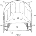
- the CV joint 60 may generally include an outer race 102 and an inner race or inner rotational member 110 that is coupled for rotation with the outer race 102. Further, the illustrated CV joint 60 is a plunging joint, i.e., that allows the inner rotational member to translate axially with respect to the outer race 102 along a plurality of tracks 104 formed in the outer race 102, e.g., during vehicle operation or installation of the CV joint to the vehicle. While the tracks 104 illustrated herein are shown as being generally straight tracks, i.e., that are aligned generally parallel to the central axis (not specifically shown) of the outer race 102, angled tracks may be employed as well, as will be described further below.
- the inner rotational member 110 may include a shaft 122. Further, the inner rotational member 110 may be coupled in any known manner to the outer race 102 for transmitting power and torque via rotational motion, while also allowing the inner rotational member 110 to translate a predetermined distance along the tracks 104.
- a plurality of rotational members such as balls, lobes, discs, wheels, or the like (not shown) may be provided that allow the outer race 102 and inner rotational member 110 to rotate together, while also allowing the inner rotational member 110 to translate axially or "plunge" within the outer race 102, and also rotate with respect to the outer race 102 to transmit power at an angle with respect to the axis of the outer race 102.
- the CV joint 60 may thereby permit the shaft 122 to rotate with respect to the outer race 102, e.g., at angles which are found in everyday driving of automotive vehicles in both the side shafts and prop shafts of these vehicles.
- the CV joint 60 may further include a boot assembly 112 that is selectively coupled to the inner rotational member 110 and the outer race 102, thereby generally sealing at least part of the inner rotational member to the outer race to provide a sealed CV joint 60.
- the outer race 102 may be provided as part of an outer race assembly 100 that includes the outer race 102, a piston 106 that is selectively moveable along the tracks of the outer race 102, and a seal 108 disposed about the piston.
- the seal 108 generally abuts the outer race 102 about substantially an entire perimeter of the piston 106, thereby generally sealing an interface between the piston 106 and the outer race 102. Accordingly, the seal 108 may prevent a lubricant (not shown) that is contained within the joint interior from intruding beyond the seal 108, as will be further described below.
- a cap 116 may be inserted into the end of the outer race 102, thereby cooperating with the boot assembly (not shown in FIG. 2 ) to generally seal the joint 60 and prevent loss of lubricant contained within the joint and also prevent intrusion of contaminants, e.g., moisture, dirt, etc.
- the piston 106 is configured to selectively move along tracks 104 provided in the outer race 102.
- the piston 106 may define a plurality of lobes 124 extending radially outward to engage the plurality of tracks 104.
- the lobes 124 and outer profile in the general axial location of the piston 106 may generally conform to a profile of the outer race 102, thereby permitting sliding movement of the piston 106 along the outer race 102 via the tracks 104.
- lobes 124 that correspond to each of the tracks in the outer race 102 due to the need for the piston 106 to move axially within the outer race 102 and the inability to provide lobes that would engage every one of the straight tracks and angled tracks across the range of axial movement of the piston. This may reduce the ability of the seal 108 to prevent intrusion of lubricant about the entire perimeter of the piston 106, but the piston 106 may still provide at least some benefit of reducing overall lubricant needed for the joint.
- the piston 106 may further define a generally circular profile at an axial position of the seal 108, thereby generally corresponding to a circular profile of the outer race 102 at the end of the outer race 102 adjacent the cap 116. While the outer race 102 and piston 106 are shown having a circular profile, other profiles may be employed so long as the profiles of the outer race 102 and piston 106 generally correspond to each other where the seal 108 is positioned on the piston 106. In one exemplary arrangement, the seal 108 abuts both the piston 106 and the outer race 102 to generally seal the interface between the piston 106 and outer race 102, while also allowing sliding movement of the piston 106 along the outer race 102. For example, as best seen in FIGS.
- the outer race 102 defines a seal engaging surface 114 extending axially along the outer race 102.
- the seal 108 is thus configured to selectively slide along the seal engaging surface 114.
- the seal engaging surface 114 defines a generally circular profile that corresponds to the profile of the piston 106, thereby allowing a consistent seal about the perimeter of the piston 106 where the seal 108 is located axially with respect to the piston 106.
- a cap 116 is inserted into the outer race 102.
- a biasing element 118 may also be disposed between the piston 106 and the cap 116, such that the biasing element 118 urges or biases the piston 106 away from the cap 116.
- the biasing element 118 is configured as a spring.
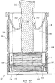
- the biasing element 118 preferably has a spring force low enough to generally permit the piston 106 to be slid toward the cap 116 (as shown in FIG. 3C ) according to the plunging of the shaft 122 into the joint 60, e.g., during installation of the CV joint 60 into a vehicle.
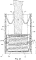
- the biasing element 118 may define a tension adequate to generally maintain the piston 106 at a maximum extension of the biasing element 118, thereby maintaining the piston 106 at a maximally extended position (as shown in FIG. 3A ) during operation of a vehicle.
- the biasing element 118 may define a sufficient biasing force to resist a force urging the piston 106 toward the cap 116 during operation.
- any lubricant contained within the joint 60 will generally be forced radially outwards by centrifugal force resulting from the joint rotation.
- the lubricant will therefore tend to accumulate along the inner surfaces of the outer race 102, and exert an axial force upon the piston 106 that is proportional to the lubricant density, the total volume of lubricant in the joint, and the contact area of the lubricant with the piston 106 when the lubricant is substantially entirely forced radially outward against the inner surfaces of the outer race 102.
- the biasing element 118 has a biasing force sufficient to resist these forces. Additionally, the biasing element 118 may have a sufficient biasing force to resist these forces and maintain the piston 106 against a reduced diameter portion of the outer race 102, as will be described further below.
- the cap 116 is inserted into one end of the outer race 102, while the inner rotational member 110 and boot assembly 112 are received in an opposite end of the outer race 102.
- the piston 106, the outer race 102, and the sealed interface between the piston 106 and the outer race 102 cooperate to define an enclosed volume A.
- a joint interior B is defined by the outer race 102, the piston 106, the sealed interface between the outer race 102 and piston 106, the inner rotational member 110, and the boot assembly 112.
- the joint interior B may be provided with lubricants to permit movement of the inner rotational member 110 within the outer race 102 during operation, e.g., sliding and rotational movement of the inner rotational member 110 with respect to the outer race 102.
- the joint interior B may generally be sealed, such that lubricants contained within the joint interior B are generally prevented from escaping from the joint interior B during operation of the joint 60.
- the joint interior B may be vented via one or more vents (not shown) to allow gases contained within the joint interior B to escape the joint interior B to the atmosphere.
- the enclosed volume A may also be generally sealed to prevent free exchange of lubricants with the joint interior B and the atmosphere, while still allowing some gaseous exchange between the joint interior B and the enclosed volume A, and also with the atmosphere, that may be necessary during operation of the joint.
- the cap 116 may be provided with any known vent mechanism (not shown) for allowing gas exchange between the enclosed volume A and the atmosphere while generally preventing loss of lubricants to the atmosphere.
- the generally sealed interface between the piston 106 and outer race 102, i.e., as defined by the seal 108, generally prevents intrusion of any lubricants or other foreign matter contained within the joint interior B from intruding into the enclosed volume A during the installation and operation of the CV joint 60, while permitting some gas exchange between the enclosed volume A and joint interior B.
- the slidable sealed interface provided by the piston 106 and seal 108 as the piston 106 is selectively translated axially with respect to the outer race 102 advantageously allows a reduced amount of lubricant to be employed within the CV joint 60. More specifically, the amount of lubricant required in a joint is generally directly proportional to the surface area presented by the outer race 102 within the joint 60. Accordingly, as the piston 106 and seal 108 generally maintain an extended position during operation of the joint 60, i.e., after installation of the joint 60 to the vehicle, the piston 106 and seal 108 effectively close off a portion of the outer race 102, reducing the amount of lubricant necessary for proper operation of the joint 60.
- piston 106 and seal 108 may be translated axially with respect to the outer race 102 toward the cap 116 during installation, as may be necessary to provide additional plunge depth of the inner rotational member 110 to allow the joint 60 to fit between the vehicle components to which it is installed, e.g., a propeller shaft and a differential.
- the enclosed volume A is therefore selectively adjustable by changing an axial position of the piston 106 with respect to the outer race 102.
- the piston 106 and seal 108 maintain a maximally extended position, e.g., as shown in FIG. 3A , that minimizes the total surface area of the outer race 102 presented within the joint interior B and maximizes the volume of the enclosed volume A.
- the biasing element 118 may bias the piston toward a maximally extended position, as described above.
- the piston 106 and seal 108 may be slid toward the cap 116 to allow additional plunging of the inner rotational member 110 and fit the CV joint 60 in between the components to which is it secured.
- the outer race 102 may define a first diameter D1 along the seal engaging surface 114, and a second diameter D2 along the plurality of tracks 104.
- the diameter D1 generally corresponds to a seal diameter defined by the seal 108, such that the diameter D1 and seal diameter 108 are generally equal, allowing for an interference fit of the seal 108 and piston 106 that allows the seal 108 to slide along the seal engaging surface 114, while also adequately preventing intrusion of lubricants from the joint interior B into the enclosed volume A.
- the second diameter D2 of the outer race 102 may be smaller than the seal diameter of the seal 108, such that the piston 106 is generally prevented from movement along said tracks beyond a predetermined distance X from the cap 116.
- the outer race 102 may thereby allow the piston 106 to slide along the seal engaging surface 114, while preventing interference of the piston 106 with the inner rotational member 110 during operation of the CV joint 60.
- the first and second diameters D1, D2 of the outer race 102 may define a transition 150 where the outer race 102 interior surface narrows from the larger diameter D1 to the maximum diameter D2 of the tracks 104.
- the transition 150 may be a sloped transition, for example as shown in FIG. 3B . Any other configuration of a transition 150 may be employed, e.g., a step feature defining a surface perpendicular to the axial travel of the piston 106.
- the transition 150 e.g., as defined in part by the reduced diameter portion of the outer race 102, may also align the piston 106 during operation of the CV joint 60, thereby enhancing the sealing effect of the piston 106 and/or seal 108.
- the reduced diameter D2 of the outer race 102 may extend about an entire circumference of the piston 106 adjacent the seal 108, such that the greater seal diameter presented by the seal 108 does not permit further movement of the piston 106 away from the cap 116, while the biasing element 118 urges the piston 106 and/or seal 108 against the reduced diameter portion of the outer race 102.
- the transition 150 may generally align the piston 106 within the outer race 102 when the piston 106 is urged into a maximally extended position furthest away from the cap 116, such that the transition 150 provides a reaction surface for the piston 106, e.g., in response to the force of the biasing element 118.
- the piston 106 is formed of a lightweight material, e.g., a plastic or lightweight steel material, so that the piston 106 does not interfere with a crush or energy absorption characteristic of the joint 60.
- the shaft 122 may generally be forced through the joint 60 and against the piston 106 and/or cap 116 with sufficient force to "punch out" the cap 116.
- This crush and "punch out” of the cap 116 may reduce transfer of vehicle crush forces along driveline components to vehicle occupant structures, thereby improving occupant safety in a crash.
- the piston 106 will necessarily absorb some degree of energy from any crush of the piston 106, this effect may be minimized by employing a lightweight plastic or steel material for the construction of the piston 106. Accordingly, the piston 106 would not interfere with the shaft 122 as it "punches out” the cap 116 from the outer race 102, at least to the extent that the piston 106 does not significantly hinder a desired energy absorption characteristic of the joint 60.
Landscapes
- Engineering & Computer Science (AREA)
- General Engineering & Computer Science (AREA)
- Mechanical Engineering (AREA)
- Sealing Devices (AREA)
Priority Applications (1)
| Application Number | Priority Date | Filing Date | Title |
|---|---|---|---|
| PL09850663T PL2491264T3 (pl) | 2009-10-21 | 2009-10-21 | Przegub równobieżny z wydłużoną kompensacją wzdłużną |
Applications Claiming Priority (1)
| Application Number | Priority Date | Filing Date | Title |
|---|---|---|---|
| PCT/US2009/061467 WO2011049563A1 (en) | 2009-10-21 | 2009-10-21 | Extended plunge constant velocity joint |
Publications (3)
| Publication Number | Publication Date |
|---|---|
| EP2491264A1 EP2491264A1 (en) | 2012-08-29 |
| EP2491264A4 EP2491264A4 (en) | 2014-10-29 |
| EP2491264B1 true EP2491264B1 (en) | 2017-08-16 |
Family
ID=43900576
Family Applications (1)
| Application Number | Title | Priority Date | Filing Date |
|---|---|---|---|
| EP09850663.7A Active EP2491264B1 (en) | 2009-10-21 | 2009-10-21 | Extended plunge constant velocity joint |
Country Status (4)
| Country | Link |
|---|---|
| US (1) | US8740711B2 (pl) |
| EP (1) | EP2491264B1 (pl) |
| PL (1) | PL2491264T3 (pl) |
| WO (1) | WO2011049563A1 (pl) |
Families Citing this family (1)
| Publication number | Priority date | Publication date | Assignee | Title |
|---|---|---|---|---|
| US11905764B1 (en) | 2020-12-09 | 2024-02-20 | IBEX Drilling Solutions, Inc. | Coupling with enhanced torsional, fatigue strength, and wear resistance |
Family Cites Families (14)
| Publication number | Priority date | Publication date | Assignee | Title |
|---|---|---|---|---|
| US1620285A (en) * | 1925-07-02 | 1927-03-08 | Link Belt Co | Flexible coupling |
| US2284199A (en) * | 1940-01-08 | 1942-05-26 | Anton F Greiner | Torque transmitting slip joint |
| DD122842A5 (pl) * | 1975-05-22 | 1976-11-05 | ||
| EP0050421B1 (en) * | 1980-10-03 | 1985-04-17 | Hardy Spicer Limited | Constant velocity ratio universal joint |
| DE3140540A1 (de) * | 1981-10-13 | 1983-04-28 | Löhr & Bromkamp GmbH, 6050 Offenbach | "gelenkwelle" |
| FR2537227B1 (fr) * | 1982-12-06 | 1987-08-21 | Centre Techn Ind Mecanique | Transmission a bille entre deux bouts d'arbres |
| US5899814A (en) | 1997-09-17 | 1999-05-04 | Dana Corporation | Vehicle drive train incorporating a plunging constant velocity joint |
| US6780114B2 (en) * | 1999-12-15 | 2004-08-24 | Ntn Corporation | Drive wheel bearing assembly |
| US6949025B1 (en) * | 2000-11-07 | 2005-09-27 | Black Warrior Wireline Corp. | Downhole motor universal joint assembly |
| US6733396B2 (en) * | 2002-03-22 | 2004-05-11 | Delphi Technologies, Inc. | Constant velocity joint |
| JP3958621B2 (ja) * | 2002-04-22 | 2007-08-15 | 株式会社日立製作所 | 動力伝達装置の緩衝機構 |
| US7278894B2 (en) | 2005-11-10 | 2007-10-09 | Gkn Driveline North America, Inc. | Propeller shaft assembly with energy absorbing material |
| JP4920465B2 (ja) * | 2007-03-20 | 2012-04-18 | Ntn株式会社 | 摺動式等速ジョイント |
| US7922590B2 (en) * | 2007-11-12 | 2011-04-12 | Gkn Driveline North America, Inc. | Grease reduction insert |
-
2009
- 2009-10-21 PL PL09850663T patent/PL2491264T3/pl unknown
- 2009-10-21 US US13/503,058 patent/US8740711B2/en active Active
- 2009-10-21 EP EP09850663.7A patent/EP2491264B1/en active Active
- 2009-10-21 WO PCT/US2009/061467 patent/WO2011049563A1/en not_active Ceased
Non-Patent Citations (1)
| Title |
|---|
| None * |
Also Published As
| Publication number | Publication date |
|---|---|
| EP2491264A4 (en) | 2014-10-29 |
| US8740711B2 (en) | 2014-06-03 |
| US20120214604A1 (en) | 2012-08-23 |
| EP2491264A1 (en) | 2012-08-29 |
| WO2011049563A1 (en) | 2011-04-28 |
| PL2491264T3 (pl) | 2018-01-31 |
Similar Documents
| Publication | Publication Date | Title |
|---|---|---|
| CA1308132C (en) | Multi-segment non-flexible boot for mechanical joint | |
| US6793581B2 (en) | Venting solution for constant velocity joint | |
| US7553238B2 (en) | Connecting assembly between a shaft journal and a constant velocity universal joint | |
| US10274020B2 (en) | Vented driveline joint | |
| US6817950B2 (en) | High angle constant velocity joint | |
| US20220258530A1 (en) | Hub- integrated-type constant-velocity joint device | |
| US7204760B2 (en) | Constant velocity joint vent | |
| US20020068638A1 (en) | Sealing assembly for constant velocity joint | |
| JPS61189323A (ja) | プランジング型の機械的動力伝達継手 | |
| US7922590B2 (en) | Grease reduction insert | |
| CN100591939C (zh) | 高角度等速万向节 | |
| GB2311117A (en) | Driveshaft for a motor vehicle driveline | |
| WO2005057035A1 (en) | Plunging constant velocity joint for a propshaft tuned for energy absorption | |
| US7008327B2 (en) | Plunging constant velocity joint for a propshaft tuned for energy absorption | |
| US7077753B2 (en) | Cross groove hybrid plunging constant velocity joint for a propshaft tuned for energy absorption | |
| US6010409A (en) | Venting constant velocity joint | |
| KR102375738B1 (ko) | 차량의 등속조인트의 그리스 씰링 구조 및 이를 포함하는 등속조인트 | |
| US7040991B2 (en) | Plunging constant velocity joint for a propshaft tuned for energy absorption | |
| US8740711B2 (en) | Extended plunge constant velocity joint | |
| US20130072312A1 (en) | High Angle Plunge Joint | |
| EP1347190B1 (en) | Constant velocity joint | |
| US6988950B2 (en) | Plunging constant velocity joint for a propshaft tuned for energy absorption | |
| US20030171154A1 (en) | Propeller shaft assembly | |
| JPH0217222A (ja) | 入力軸周囲の密封を改善した機械継手用多要素ブーツ | |
| US12535108B2 (en) | Constant velocity universal joint and manufacturing method of constant velocity universal joint |
Legal Events
| Date | Code | Title | Description |
|---|---|---|---|
| PUAI | Public reference made under article 153(3) epc to a published international application that has entered the european phase |
Free format text: ORIGINAL CODE: 0009012 |
|
| 17P | Request for examination filed |
Effective date: 20120518 |
|
| AK | Designated contracting states |
Kind code of ref document: A1 Designated state(s): AT BE BG CH CY CZ DE DK EE ES FI FR GB GR HR HU IE IS IT LI LT LU LV MC MK MT NL NO PL PT RO SE SI SK SM TR |
|
| DAX | Request for extension of the european patent (deleted) | ||
| A4 | Supplementary search report drawn up and despatched |
Effective date: 20140925 |
|
| RIC1 | Information provided on ipc code assigned before grant |
Ipc: F16D 3/20 20060101AFI20140919BHEP Ipc: F16D 3/00 20060101ALI20140919BHEP Ipc: F16D 3/22 20060101ALI20140919BHEP |
|
| GRAP | Despatch of communication of intention to grant a patent |
Free format text: ORIGINAL CODE: EPIDOSNIGR1 |
|
| STAA | Information on the status of an ep patent application or granted ep patent |
Free format text: STATUS: GRANT OF PATENT IS INTENDED |
|
| INTG | Intention to grant announced |
Effective date: 20170119 |
|
| GRAS | Grant fee paid |
Free format text: ORIGINAL CODE: EPIDOSNIGR3 |
|
| GRAJ | Information related to disapproval of communication of intention to grant by the applicant or resumption of examination proceedings by the epo deleted |
Free format text: ORIGINAL CODE: EPIDOSDIGR1 |
|
| GRAL | Information related to payment of fee for publishing/printing deleted |
Free format text: ORIGINAL CODE: EPIDOSDIGR3 |
|
| STAA | Information on the status of an ep patent application or granted ep patent |
Free format text: STATUS: REQUEST FOR EXAMINATION WAS MADE |
|
| GRAP | Despatch of communication of intention to grant a patent |
Free format text: ORIGINAL CODE: EPIDOSNIGR1 |
|
| STAA | Information on the status of an ep patent application or granted ep patent |
Free format text: STATUS: GRANT OF PATENT IS INTENDED |
|
| RAP1 | Party data changed (applicant data changed or rights of an application transferred) |
Owner name: GKN DRIVELINE NORTH AMERICA, INC. |
|
| INTC | Intention to grant announced (deleted) | ||
| GRAA | (expected) grant |
Free format text: ORIGINAL CODE: 0009210 |
|
| STAA | Information on the status of an ep patent application or granted ep patent |
Free format text: STATUS: THE PATENT HAS BEEN GRANTED |
|
| INTG | Intention to grant announced |
Effective date: 20170623 |
|
| AK | Designated contracting states |
Kind code of ref document: B1 Designated state(s): AT BE BG CH CY CZ DE DK EE ES FI FR GB GR HR HU IE IS IT LI LT LU LV MC MK MT NL NO PL PT RO SE SI SK SM TR |
|
| REG | Reference to a national code |
Ref country code: GB Ref legal event code: FG4D |
|
| REG | Reference to a national code |
Ref country code: CH Ref legal event code: EP |
|
| REG | Reference to a national code |
Ref country code: IE Ref legal event code: FG4D |
|
| REG | Reference to a national code |
Ref country code: AT Ref legal event code: REF Ref document number: 919362 Country of ref document: AT Kind code of ref document: T Effective date: 20170915 |
|
| REG | Reference to a national code |
Ref country code: DE Ref legal event code: R096 Ref document number: 602009047824 Country of ref document: DE |
|
| REG | Reference to a national code |
Ref country code: NL Ref legal event code: MP Effective date: 20170816 |
|
| REG | Reference to a national code |
Ref country code: LT Ref legal event code: MG4D |
|
| REG | Reference to a national code |
Ref country code: AT Ref legal event code: MK05 Ref document number: 919362 Country of ref document: AT Kind code of ref document: T Effective date: 20170816 |
|
| PG25 | Lapsed in a contracting state [announced via postgrant information from national office to epo] |
Ref country code: SE Free format text: LAPSE BECAUSE OF FAILURE TO SUBMIT A TRANSLATION OF THE DESCRIPTION OR TO PAY THE FEE WITHIN THE PRESCRIBED TIME-LIMIT Effective date: 20170816 Ref country code: FI Free format text: LAPSE BECAUSE OF FAILURE TO SUBMIT A TRANSLATION OF THE DESCRIPTION OR TO PAY THE FEE WITHIN THE PRESCRIBED TIME-LIMIT Effective date: 20170816 Ref country code: NL Free format text: LAPSE BECAUSE OF FAILURE TO SUBMIT A TRANSLATION OF THE DESCRIPTION OR TO PAY THE FEE WITHIN THE PRESCRIBED TIME-LIMIT Effective date: 20170816 Ref country code: LT Free format text: LAPSE BECAUSE OF FAILURE TO SUBMIT A TRANSLATION OF THE DESCRIPTION OR TO PAY THE FEE WITHIN THE PRESCRIBED TIME-LIMIT Effective date: 20170816 Ref country code: AT Free format text: LAPSE BECAUSE OF FAILURE TO SUBMIT A TRANSLATION OF THE DESCRIPTION OR TO PAY THE FEE WITHIN THE PRESCRIBED TIME-LIMIT Effective date: 20170816 Ref country code: NO Free format text: LAPSE BECAUSE OF FAILURE TO SUBMIT A TRANSLATION OF THE DESCRIPTION OR TO PAY THE FEE WITHIN THE PRESCRIBED TIME-LIMIT Effective date: 20171116 |
|
| PG25 | Lapsed in a contracting state [announced via postgrant information from national office to epo] |
Ref country code: GR Free format text: LAPSE BECAUSE OF FAILURE TO SUBMIT A TRANSLATION OF THE DESCRIPTION OR TO PAY THE FEE WITHIN THE PRESCRIBED TIME-LIMIT Effective date: 20171117 Ref country code: IS Free format text: LAPSE BECAUSE OF FAILURE TO SUBMIT A TRANSLATION OF THE DESCRIPTION OR TO PAY THE FEE WITHIN THE PRESCRIBED TIME-LIMIT Effective date: 20171216 Ref country code: BG Free format text: LAPSE BECAUSE OF FAILURE TO SUBMIT A TRANSLATION OF THE DESCRIPTION OR TO PAY THE FEE WITHIN THE PRESCRIBED TIME-LIMIT Effective date: 20171116 Ref country code: LV Free format text: LAPSE BECAUSE OF FAILURE TO SUBMIT A TRANSLATION OF THE DESCRIPTION OR TO PAY THE FEE WITHIN THE PRESCRIBED TIME-LIMIT Effective date: 20170816 Ref country code: ES Free format text: LAPSE BECAUSE OF FAILURE TO SUBMIT A TRANSLATION OF THE DESCRIPTION OR TO PAY THE FEE WITHIN THE PRESCRIBED TIME-LIMIT Effective date: 20170816 |
|
| PG25 | Lapsed in a contracting state [announced via postgrant information from national office to epo] |
Ref country code: CZ Free format text: LAPSE BECAUSE OF FAILURE TO SUBMIT A TRANSLATION OF THE DESCRIPTION OR TO PAY THE FEE WITHIN THE PRESCRIBED TIME-LIMIT Effective date: 20170816 Ref country code: RO Free format text: LAPSE BECAUSE OF FAILURE TO SUBMIT A TRANSLATION OF THE DESCRIPTION OR TO PAY THE FEE WITHIN THE PRESCRIBED TIME-LIMIT Effective date: 20170816 Ref country code: DK Free format text: LAPSE BECAUSE OF FAILURE TO SUBMIT A TRANSLATION OF THE DESCRIPTION OR TO PAY THE FEE WITHIN THE PRESCRIBED TIME-LIMIT Effective date: 20170816 |
|
| REG | Reference to a national code |
Ref country code: DE Ref legal event code: R097 Ref document number: 602009047824 Country of ref document: DE |
|
| PG25 | Lapsed in a contracting state [announced via postgrant information from national office to epo] |
Ref country code: IT Free format text: LAPSE BECAUSE OF FAILURE TO SUBMIT A TRANSLATION OF THE DESCRIPTION OR TO PAY THE FEE WITHIN THE PRESCRIBED TIME-LIMIT Effective date: 20170816 Ref country code: EE Free format text: LAPSE BECAUSE OF FAILURE TO SUBMIT A TRANSLATION OF THE DESCRIPTION OR TO PAY THE FEE WITHIN THE PRESCRIBED TIME-LIMIT Effective date: 20170816 Ref country code: MC Free format text: LAPSE BECAUSE OF FAILURE TO SUBMIT A TRANSLATION OF THE DESCRIPTION OR TO PAY THE FEE WITHIN THE PRESCRIBED TIME-LIMIT Effective date: 20170816 Ref country code: SK Free format text: LAPSE BECAUSE OF FAILURE TO SUBMIT A TRANSLATION OF THE DESCRIPTION OR TO PAY THE FEE WITHIN THE PRESCRIBED TIME-LIMIT Effective date: 20170816 Ref country code: SM Free format text: LAPSE BECAUSE OF FAILURE TO SUBMIT A TRANSLATION OF THE DESCRIPTION OR TO PAY THE FEE WITHIN THE PRESCRIBED TIME-LIMIT Effective date: 20170816 |
|
| REG | Reference to a national code |
Ref country code: CH Ref legal event code: PL |
|
| PLBE | No opposition filed within time limit |
Free format text: ORIGINAL CODE: 0009261 |
|
| STAA | Information on the status of an ep patent application or granted ep patent |
Free format text: STATUS: NO OPPOSITION FILED WITHIN TIME LIMIT |
|
| 26N | No opposition filed |
Effective date: 20180517 |
|
| REG | Reference to a national code |
Ref country code: IE Ref legal event code: MM4A |
|
| REG | Reference to a national code |
Ref country code: FR Ref legal event code: ST Effective date: 20180629 |
|
| PG25 | Lapsed in a contracting state [announced via postgrant information from national office to epo] |
Ref country code: CH Free format text: LAPSE BECAUSE OF NON-PAYMENT OF DUE FEES Effective date: 20171031 Ref country code: LU Free format text: LAPSE BECAUSE OF NON-PAYMENT OF DUE FEES Effective date: 20171021 Ref country code: LI Free format text: LAPSE BECAUSE OF NON-PAYMENT OF DUE FEES Effective date: 20171031 |
|
| REG | Reference to a national code |
Ref country code: BE Ref legal event code: MM Effective date: 20171031 |
|
| PG25 | Lapsed in a contracting state [announced via postgrant information from national office to epo] |
Ref country code: SI Free format text: LAPSE BECAUSE OF FAILURE TO SUBMIT A TRANSLATION OF THE DESCRIPTION OR TO PAY THE FEE WITHIN THE PRESCRIBED TIME-LIMIT Effective date: 20170816 Ref country code: BE Free format text: LAPSE BECAUSE OF NON-PAYMENT OF DUE FEES Effective date: 20171031 Ref country code: FR Free format text: LAPSE BECAUSE OF NON-PAYMENT OF DUE FEES Effective date: 20171031 |
|
| PG25 | Lapsed in a contracting state [announced via postgrant information from national office to epo] |
Ref country code: MT Free format text: LAPSE BECAUSE OF NON-PAYMENT OF DUE FEES Effective date: 20171021 |
|
| PG25 | Lapsed in a contracting state [announced via postgrant information from national office to epo] |
Ref country code: IE Free format text: LAPSE BECAUSE OF NON-PAYMENT OF DUE FEES Effective date: 20171021 |
|
| PG25 | Lapsed in a contracting state [announced via postgrant information from national office to epo] |
Ref country code: HU Free format text: LAPSE BECAUSE OF FAILURE TO SUBMIT A TRANSLATION OF THE DESCRIPTION OR TO PAY THE FEE WITHIN THE PRESCRIBED TIME-LIMIT; INVALID AB INITIO Effective date: 20091021 |
|
| PG25 | Lapsed in a contracting state [announced via postgrant information from national office to epo] |
Ref country code: CY Free format text: LAPSE BECAUSE OF NON-PAYMENT OF DUE FEES Effective date: 20170816 |
|
| PG25 | Lapsed in a contracting state [announced via postgrant information from national office to epo] |
Ref country code: MK Free format text: LAPSE BECAUSE OF FAILURE TO SUBMIT A TRANSLATION OF THE DESCRIPTION OR TO PAY THE FEE WITHIN THE PRESCRIBED TIME-LIMIT Effective date: 20170816 |
|
| PG25 | Lapsed in a contracting state [announced via postgrant information from national office to epo] |
Ref country code: TR Free format text: LAPSE BECAUSE OF FAILURE TO SUBMIT A TRANSLATION OF THE DESCRIPTION OR TO PAY THE FEE WITHIN THE PRESCRIBED TIME-LIMIT Effective date: 20170816 |
|
| PG25 | Lapsed in a contracting state [announced via postgrant information from national office to epo] |
Ref country code: PT Free format text: LAPSE BECAUSE OF FAILURE TO SUBMIT A TRANSLATION OF THE DESCRIPTION OR TO PAY THE FEE WITHIN THE PRESCRIBED TIME-LIMIT Effective date: 20170816 |
|
| PG25 | Lapsed in a contracting state [announced via postgrant information from national office to epo] |
Ref country code: HR Free format text: LAPSE BECAUSE OF FAILURE TO SUBMIT A TRANSLATION OF THE DESCRIPTION OR TO PAY THE FEE WITHIN THE PRESCRIBED TIME-LIMIT Effective date: 20170816 |
|
| PGFP | Annual fee paid to national office [announced via postgrant information from national office to epo] |
Ref country code: PL Payment date: 20241011 Year of fee payment: 16 |
|
| PGFP | Annual fee paid to national office [announced via postgrant information from national office to epo] |
Ref country code: GB Payment date: 20241024 Year of fee payment: 16 |
|
| PGFP | Annual fee paid to national office [announced via postgrant information from national office to epo] |
Ref country code: DE Payment date: 20251020 Year of fee payment: 17 |
|
| GBPC | Gb: european patent ceased through non-payment of renewal fee |
Effective date: 20251021 |
|
| PG25 | Lapsed in a contracting state [announced via postgrant information from national office to epo] |
Ref country code: GB Free format text: LAPSE BECAUSE OF NON-PAYMENT OF DUE FEES Effective date: 20251021 |