EP2491204B1 - Parkvorrichtung - Google Patents
Parkvorrichtung Download PDFInfo
- Publication number
- EP2491204B1 EP2491204B1 EP10790673.7A EP10790673A EP2491204B1 EP 2491204 B1 EP2491204 B1 EP 2491204B1 EP 10790673 A EP10790673 A EP 10790673A EP 2491204 B1 EP2491204 B1 EP 2491204B1
- Authority
- EP
- European Patent Office
- Prior art keywords
- trolley
- wheels
- parking device
- parking
- vehicle
- Prior art date
- Legal status (The legal status is an assumption and is not a legal conclusion. Google has not performed a legal analysis and makes no representation as to the accuracy of the status listed.)
- Active
Links
Images



Classifications
-
- E—FIXED CONSTRUCTIONS
- E04—BUILDING
- E04H—BUILDINGS OR LIKE STRUCTURES FOR PARTICULAR PURPOSES; SWIMMING OR SPLASH BATHS OR POOLS; MASTS; FENCING; TENTS OR CANOPIES, IN GENERAL
- E04H6/00—Buildings for parking cars, rolling-stock, aircraft, vessels or like vehicles, e.g. garages
- E04H6/08—Garages for many vehicles
- E04H6/12—Garages for many vehicles with mechanical means for shifting or lifting vehicles
- E04H6/18—Garages for many vehicles with mechanical means for shifting or lifting vehicles with means for transport in vertical direction only or independently in vertical and horizontal directions
- E04H6/22—Garages for many vehicles with mechanical means for shifting or lifting vehicles with means for transport in vertical direction only or independently in vertical and horizontal directions characterised by use of movable platforms for horizontal transport, i.e. cars being permanently parked on palettes
-
- E—FIXED CONSTRUCTIONS
- E04—BUILDING
- E04H—BUILDINGS OR LIKE STRUCTURES FOR PARTICULAR PURPOSES; SWIMMING OR SPLASH BATHS OR POOLS; MASTS; FENCING; TENTS OR CANOPIES, IN GENERAL
- E04H6/00—Buildings for parking cars, rolling-stock, aircraft, vessels or like vehicles, e.g. garages
- E04H6/42—Devices or arrangements peculiar to garages, not covered elsewhere, e.g. securing devices, safety devices, monitoring and operating schemes; centering devices
- E04H6/422—Automatically operated car-parks
Definitions
- the present invention refers to a parking device of the type suitable for transporting vehicles in a guided fashion into and out from defined spaces, such as lockups, parking spaces, garages, car parks, car workshop areas and the like, without the driver having to be present inside the vehicle.
- Parking devices of the type specified above are known that comprise chain or belt-operated mechanisms or mobile platforms on which the vehicle can be positioned and through which the vehicle can be transported into a parking space after the driver has got out from the vehicle itself and, similarly, it can be taken out from the parking space with nobody inside.
- the actuation of known parking devices usually occurs through a user interface, for example a push-button panel that can be easily accessed from outside of the parking space and connected with one or more electric actuation motors to move the vehicle into and out from the parking space.
- Known parking devices whilst satisfactory from the point of view of operation and reliability, have some drawbacks resulting from difficult, expensive and invasive installation that often requires major work on the masonry of the garage and on the floor of the parking area, as well as from a limited versatility with reference to the shape and size of the garage, often requiring specially-made adaptations and manufacturing in short series of parking devices that are often different according to their place of installation.
- WO 91/10794 A1 describe a parking device having features of the preamble of claim 1.
- the purpose of the present invention is therefore to provide a parking device having characteristics such as to avoid the quoted drawbacks with reference to the prior art.
- a particular purpose of the present invention is to propose a parking device that reconciles the requirements of remote controlled transportation of a vehicle in narrow parking spaces with the requirements of simple, cost-effective and non-invasive installation and of easy adaptation to shapes and sizes of different garages.
- a parking device for remote controlled transportation of a vehicle into a parking space and out from the parking space, comprising:
- the parking device in particular to the guide of the trolley able to be mounted in the parking space and to the electric motor on-board the trolley itself assembly is simple and not very invasive and the structure is strong and reliable, easily adapting to various shapes and sizes of parking spaces.
- the trolley rests through its wheels directly on a pre-existing floor of the parking space and the guiding means comprise two guide rails that laterally engage the trolley, in particular the wheels themselves.
- the trolley comprises two half-platforms spaced apart and configured to respectively receive a right wheel and a left wheel of the same axle of the vehicle, in which the two half-platforms are structurally connected together through only one or more axles that carry the wheels of the trolley.
- the electric motor and a reducing transmission are pre-assembled to form a gearmotor block screwed to the trolley and having an output shaft directly connected with a driving axle of the axles that carry the wheels.
- the device comprises end stops both going in and out configured so as to interrupt the movement of the trolley when one or more predetermined end stop positions are reached.
- the ends stops can comprise stop blocks configured to interfere with the trajectory of motion of the trolley or optical, magnetic or mechanical sensors (switches) configured to generate and send an end stop signal to the control unit, which interrupts the power supply to the motor.
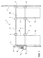
- a parking device is wholly indicated with reference numeral 1.
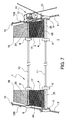
- the device 1 is configured for remote controlled transportation of a vehicle into a parking space 2 and out from the parking space 2 and comprises a trolley 3 with a support platform 4 configured to receive and support a part of the vehicle and a plurality of wheels 5, 6 for moving the trolley 3 into and out from the parking space 2, guiding means, for example two elongated guiding profiles 7, able to be mounted at the parking space 2, in particular on its floor, and configured to collaborate with the trolley 3 to ensure its guided movement, as well as an electric motor 8 mounted directly on the trolley 3 and connected through transmission means 13, for example a reduction gear, with at least one or more driving wheels 6 of the aforementioned wheels 5, 6 to actuate them.
- guiding means for example two elongated guiding profiles 7, able to be mounted at the parking space 2, in particular on its floor, and configured to collaborate with the trolley 3 to ensure its guided movement, as well as an electric motor 8 mounted directly on the trolley 3 and connected through transmission means 13, for example a reduction gear, with at
- a user control member 9 to control the parking device 1 and a control unit 10 in signal connection with the user control member 9 and with the electric motor 8 and configured to drive the electric motor 8 as a function of signals received from the user control member 9.
- the trolley 3 rests through its wheels directly on a pre-existing floor of the parking space 2 and the guides 7 laterally engage the trolley 3 and in particular its wheels 5, 6 and/or determine their path of motion.
- the trolley 3 comprises two half-platforms 4A, 4B spaced apart and configured to receive a right wheel and a left wheel, respectively, of the same axle of the vehicle, in which the two half-platforms 4A, 4B are structurally connected to one another just through one or more axles 11, 12 that carry the wheels 5, 6 of the trolley 3.
- the electric motor 8 and a reducing transmission 13 are pre-assembled to form a gearmotor block 14 screwed to the trolley 3 and having an output shaft directly connected with a driving axle 12 of the axles 11, 12.
- the gearmotor block 14 can be connected in different areas of the trolley 3 and it preferably directly engages the driving axle 12.
- end stop devices 15 can also be end stop devices 15 both going in and out, configured so as to interrupt the movement of the trolley 3 when one or more predetermined end stop positions are reached.
- the end stop devices 15 can comprise mechanical stop blocks 15A configured to interfere with the trajectory of motion of the trolley 3 or optical, magnetic or mechanical sensors 15B (for example switches) configured to generate an end stop signal when the trolley 3 reaches an end stop position and to send such an end stop signal to the control unit 10, which interrupts the electrical power supply to the motor 8.
- the stop sensors 15B can comprise an actuation block suitable for actuating a tumbler switch, in which such an actuation block comprises a magnet and it is directly connected to the guides through gluing, so that the magnet provides the compression force during the setting of the glue. In this way, there is no need to perforate the guides and fix the actuation blocks through screws.
- At least the mechanical stop block 15a that determines the mechanical end stop at the exit of the parking space comprises at least one seat 23 formed at one of the guides 7 and suitable for receiving or engaging an engagement portion 24 connected to the platform 4 or to one of the supporting half-platforms 4A, 4B so as to prevent the engagement portion 24 and, therefore, the platform 4 or half-platforms 4A, 4B from lifting up while the wheels of the vehicle go up and/or down.
- the seat 23 is formed from a tubular profile welded or screwed to the guide 7 and the engagement portion 24 comprises a bar or pin extending in the direction of motion of the device and connected to a tab projecting from the platform or half-platform 4, 4A, 4B.
- the guides 7 are arranged at the inner wheels 5, 6 of the device 1 so as not to obstruct the parking of a vehicle without the help of the device itself and to leave the space at the two side of the vehicle free.
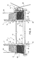
- the guides 7 comprise a U-shaped profile 25 the cavity of which receives the wheels 5, 6 so as to guide them on both sides ( figure 8 ).
- the device 1 comprises one or more reference rods 26 positioned at the outer sides of the platform 4 or of the half-platforms 4A, 4B in order to make it easier for the vehicle to correctly go up onto the platform.
- the support platform 4, i.e. the support half-platforms 4A, 4B can have dimensions such as to receive just a pair of wheels of the vehicle, dragging the other pair of (idle) wheels or, in particular for vehicles with four wheel drive and automatic gearshift, the support platform 4 or the support half-platforms 4A, 4B can have dimensions such as to receive all of the wheels. In this way, the device works well with the "parking" mode of vehicles with automatic gearshift.
- the support platform 4, or else the support half-platforms 4A, 4B comprise one or more ramps 16 defining an inclined plane that makes it easier for the wheels of a vehicle to go up onto and down from the platform itself.
- the ramps 16 can advantageously be hinged to an elevated portion 17 of the platform 4 and further supported by one or more support rollers 18 arranged in a front area on the lower side of the ramps 16.
- the front end of the ramps 16 can be elastically supported, for example through a spring 19 that acts between the structure of the trolley 3 and the ramp 16.
- the elevated portion(s) 17 of the support platform 4 comprise holding barriers 20, for example configured as depressions or low holding walls, suitable for preventing the wheels of the vehicle from rolling when there are slight differences in level or in response to the movement of the trolley 3.
- the user control member 9 comprises a remote control in data connection with a receiver of the control unit 10 (arranged in the parking space or on-board the trolley, preferably integrated in the gearmotor block).
- the user control member 9 can have three buttons: a first button to actuate the entry into the parking space 2, a second button to actuate the exit from the parking space 2 and a third button that stops the trolley 3 from moving at any time.
- the electrical connection of the motor 8 can be made through an electric power supply cable 22 able to be tightened through a cable-winder 21 that can be fixed to the parking space 2.
- the trolley 3 In order to make the vehicle enter into the parking space 2, the trolley 3 must be positioned at the entry to such a space, in order to allow the vehicle to go up with the front or rear wheels and with the help of the ramps 16, onto the platforms 4A, 4B, by inserting just the front or rear end of the vehicle inside the parking space.
- the wheels 5, 6 of the trolley 3 will be correctly directed by the guides 7 arranged flush with wheels and fixed with simple anchors to the floor of the parking space 2.
- manual switching means 27, 28 are foreseen that are suitable for coupling and decoupling the movement of the driving wheels 6 from the motor 8, so as to allow idle movement of the device 1 in the case of an interruption to the electrical power supply. This would allow the device 1 to be pushed together with the vehicle resting on it manually into and out from the parking space.
- the manual switching means 27, 28 can comprise a coupling key 27 able to be removably inserted into a coupling seat 28 formed in part in a drive shaft 29 of the motor 8 and in part in a transmission shaft 30 of the transmission means 13, in which such a transmission shaft 30 is preferably formed directly by the driving axle 12.
- the coupling key 27 and the coupling seat 28 are formed so as to jointly make a shape coupling of the drive shaft 29 and of the transmission shaft 30; 12 rotating as a unit, and the coupling key 27 itself comprises a manual gripping portion 31 arranged outside of the motor 8 so as to make it easier to be accessed manually by the user.
- the parking device 1 has numerous advantages.
- the device 1 is very compact, allowing free access to the car parking space, like, for example, for storing various goods (often, indeed, particularly deep lockups make it possible to put up shelves on which various objects and material can be placed), without taking up excessive bulk, without creating dangers and obstacles and without occupying precious space.
- the device 1 is simple to make a strong with few components, which makes both installation and maintenance easier.
- the simplicity of construction of the device 1 has the correlated benefit of being able to adapt the device 1 to various types of vehicle and parking space/lockup, by simply using longer or shorter axles and lengthening or shortening the travel of the device itself.
Landscapes
- Engineering & Computer Science (AREA)
- Architecture (AREA)
- Civil Engineering (AREA)
- Structural Engineering (AREA)
- Mechanical Engineering (AREA)
- Handcart (AREA)
- Apparatuses And Processes For Manufacturing Resistors (AREA)
- Physical Deposition Of Substances That Are Components Of Semiconductor Devices (AREA)
- Vehicle Interior And Exterior Ornaments, Soundproofing, And Insulation (AREA)
Claims (16)
- Parkvorrichtung (1) für die ferngesteuerte Beförderung eines Fahrzeugs in einen Parkplatz (2) und aus diesem heraus, die Folgendes umfasst:einen Spurwagen (3) mit einer Trageplattform (4), die darauf ausgelegt ist, einen Teil des Fahrzeugs zu tragen und mehrere Räder (5, 6) zum Bewegen des Spurwagens (3) in und aus dem Parkplatz (2) heraus,Führungselemente (7), die am Parkplatz (2) montiert und so konfiguriert werden können, dass sie mit dem Spurwagen (3) zusammenwirken, um seinen Bewegungspfad zu bestimmen,einen Motor (8), der direkt auf den Spurwagen (3) montiert und mittels Getriebevorrichtungen (13) mit einem oder mehreren Antriebsrädern (6) der genannten Räder (5, 6) verbunden ist, um diese zu betätigen,ein Benutzer-Steuerelement (9) zur Steuerung der Parkvorrichtung (1),eine Steuereinheit (10) in Signalverbindung mit dem Benutzer-Steuerelement (9) und dem Elektromotor (8), die darauf ausgelegt ist, den Elektromotor (8) als eine Funktion von Signalen anzutreiben, die von dem Benutzer-Steuerelement (9) empfangen werden, dadurch gekennzeichnet, dass der genannte Spurwagen (3) zwei Halbplattformen (4A, 4B) umfasst, die im Abstand zueinander liegen und darauf ausgelegt sind, jeweils ein rechtes und ein linkes Rad derselben Achse des Fahrzeugs zu empfangen, wobei die beiden Halbplattformen (4A, 4B) strukturell nur über eine oder mehrere weitere Achsen (11, 12) miteinander verbunden sind, die die Räder (5, 6) tragen.
- Parkvorrichtung (1) nach Anspruch 1, die den genannten Parkplatz (2) umfasst, in der der Spurwagen (3) durch die genannten Räder (5, 6) direkt auf dem Boden des Parkplatzes (2) ruht und die Führungen (7) seitlich seine Räder (5, 6) ankuppeln, um ihren Bewegungspfad zu bestimmen.
- Parkvorrichtung (1) nach einem beliebigen der vorstehenden Ansprüche, bei der der genannte Elektromotor (8) und ein Untersetzungsgetriebe (13) vormontiert sind, um einen Getriebemotorblock (14) zu bilden, der auf dem Spurwagen (3) verschraubt ist und dessen Abtriebswelle direkt mit einer Antriebsachse (12) der Achsen (11, 12) verbunden ist.
- Parkvorrichtung (1) nach einem beliebigen der vorstehenden Ansprüche, die Endanschlagvorrichtungen (15) umfasst und so ausgelegt ist, dass die Bewegung des Spurwagens (3) unterbrochen wird, wenn eine oder mehrere zuvor festgelegte Endanschlagpositionen erreicht werden.
- Parkvorrichtung (1) nach Anspruch 4, bei der die genannten Endanschlagvorrichtungen (15) mechanische Stoppblöcke (15°) umfassen, die darauf ausgelegt sind, die Bewegungsbahn des Wagens (3) zu schneiden.
- Parkvorrichtung (1) nach Anspruch 4, bei der die genannten Endanschlagvorrichtungen (15) magnetische oder mechanische optische Sensoren (15B) umfassen, die darauf ausgelegt sind, ein Endanschlagsignal zu erzeugen, wenn der Wagen (3) eine Endanschlagposition erreicht und ein solches Endanschlagsignal an die Steuereinheit (10) zu senden, die als Antwort auf das Endanschlagsignal die elektrische Stromversorgung zum Motor (8) unterbricht.
- Parkvorrichtung (1) nach einem beliebigen der vorstehenden Ansprüche, bei der die Trageplattform (4, 4A, 4B) eine oder mehrere Rampen (16) umfasst, die eine geneigte Ebene bilden, um den Rädern eines Automobils das Herauf- und Herunterfahren zu erleichtern.
- Parkvorrichtung (1) nach Anspruch 7, bei der die genannten Rampen (16) mit Scharnieren an einem erhöhten Teil (17) der Plattform (4) befestigt und außerdem von einer oder mehreren Stützrollen (18) getragen werden, die an der unteren Seite der Rampen (16) angeordnet sind oder von einer Feder (19), die zwischen den Strukturen des Spurwagens (3) und der Rampe (16) wirkt.
- Parkvorrichtung (1) nach einem beliebigen der vorstehenden Ansprüche, bei der die Trageplattform (4) Haltebarrieren (20) umfasst, die geeignet sind, das Rollen der Fahrzeugräder zu unterbinden.
- Parkvorrichtung (1) nach einem beliebigen der vorstehenden Ansprüche, die Endanschlagsensoren (15B) mit einem Antriebsblock umfasst, der zum Betätigen eines Kippschalters geeignet ist, bei der der genannten Antriebsblock einen Magneten umfasst und durch Verkleben mit den Führungen verbunden ist.
- Parkvorrichtung (1) nach einem beliebigen der vorstehenden Ansprüche, die einen mechanischen Stoppblock (15A) umfasst, der einen mechanischen Endanschlag am Ausgang der Parkvorrichtung bildet, wobei der genannte mechanische Stoppblock (15A) über mindestens einen Sitz (23) verfügt, der an einer der Führungen (7) ausgeformt und geeignet ist, einen Kupplungsteil (24) anzukuppeln, der mit der Plattform (4) verbunden ist, um dem Anheben der Plattform (4) vorzubeugen, während die Räder des Fahrzeugs sich nach oben und/oder unten bewegen.
- Parkvorrichtung (1) nach einem beliebigen der vorstehenden Ansprüche, bei der die genannten Führungen (7) an den Innenrädern (5, 6) der Vorrichtung (1) angeordnet sind, so dass der Raum an den beiden Seiten des Fahrzeugs frei bleibt.
- Parkvorrichtung (1) nach einem beliebigen der vorstehenden Ansprüche, bei der die genannten Führungen (7) ein U-förmiges Profil (25) umfassen, dessen Kavität die Räder (5, 6) aufnimmt, um sie auf beiden Seiten zu führen.
- Parkvorrichtung (1) nach einem beliebigen der vorstehenden Ansprüche, die eine oder mehrere Bezugsstangen (26) umfasst, die an den Außenseiten der Plattform (4) positioniert sind, um es dem Fahrzeug zu erleichtern, sich korrekt auf die Plattform zu bewegen.
- Parkvorrichtung (1) nach einem beliebigen der vorstehenden Ansprüche, die manuelle Schaltvorrichtungen (27, 28) umfassen, die sich zum Ein- und Auskuppeln der Bewegung der Antriebsräder (6) vom Motor (8) eignet, so dass sich die Vorrichtung (1) im Fall der Unterbrechung der Stromversorgung im Leerlauf bewegen kann.
- Parkvorrichtung (1) nach dem vorstehenden Anspruch, bei der die genannten Schaltvorrichtungen (27, 28) eine Kupplungspassfeder umfassen, die entfernbar in einen Kupplungssitz (28) eingesetzt werden kann, der zum Teil in einer Antriebswelle (29) des Motors (8) und zum Teil in einer Getriebewelle (30, 12) der Getriebeelemente (13) gebildet wird, bei der die genannte Kupplungspassfeder (27) und der genannte Kupplungssitz (28) so geformt sind, dass sie zusammen eine Formkupplung der Antriebswelle (29) und der Getriebewelle (30, 12) bilden, die als eine Einheit dreht, wobei die Kupplungspassfeder (27) einen manuellen Eingriffteil (31) aufweist, der außerhalb des Motors (8) angeordnet ist.
Applications Claiming Priority (2)
| Application Number | Priority Date | Filing Date | Title |
|---|---|---|---|
| ITMI2009A001815A IT1396216B1 (it) | 2009-10-20 | 2009-10-20 | Dispositivo di parcheggio |
| PCT/IT2010/000419 WO2011048620A1 (en) | 2009-10-20 | 2010-10-18 | Parking device |
Publications (2)
| Publication Number | Publication Date |
|---|---|
| EP2491204A1 EP2491204A1 (de) | 2012-08-29 |
| EP2491204B1 true EP2491204B1 (de) | 2013-12-25 |
Family
ID=42316011
Family Applications (1)
| Application Number | Title | Priority Date | Filing Date |
|---|---|---|---|
| EP10790673.7A Active EP2491204B1 (de) | 2009-10-20 | 2010-10-18 | Parkvorrichtung |
Country Status (4)
| Country | Link |
|---|---|
| EP (1) | EP2491204B1 (de) |
| ES (1) | ES2453091T3 (de) |
| IT (1) | IT1396216B1 (de) |
| WO (1) | WO2011048620A1 (de) |
Cited By (1)
| Publication number | Priority date | Publication date | Assignee | Title |
|---|---|---|---|---|
| EP4717851A1 (de) | 2024-09-25 | 2026-04-01 | Green Pack S.R.L. | Verbesserte ausrüstung zum automatischen parken für ein fahrzeug und/oder wasserfahrzeug |
Families Citing this family (5)
| Publication number | Priority date | Publication date | Assignee | Title |
|---|---|---|---|---|
| IT201600130236A1 (it) * | 2016-12-22 | 2018-06-22 | Emanuele Molon | Sistema di parcheggio assistito per autoveicoli. |
| GB2561857B (en) * | 2017-04-25 | 2019-08-14 | My Parker Ltd | A vehicle parking device |
| DE102017220587B4 (de) * | 2017-11-17 | 2022-06-23 | Robert Bosch Gmbh | Konzept zum Bewegen eines Kraftfahrzeugs innerhalb eines Parkplatzes |
| CN108252241B (zh) * | 2018-02-11 | 2019-03-19 | 刘优然 | 一种停车收费系统及收费方法 |
| CN110847667A (zh) * | 2019-11-04 | 2020-02-28 | 徐州康博智能控制仪表有限公司 | 一种停车位占位系统及其控制方法 |
Family Cites Families (7)
| Publication number | Priority date | Publication date | Assignee | Title |
|---|---|---|---|---|
| JPS463289Y1 (de) * | 1967-03-31 | 1971-02-04 | ||
| AU3756489A (en) * | 1988-06-09 | 1990-01-05 | Hans Hammer | Parking system and process for automatic parking of vehicles |
| EP0511995A4 (en) * | 1990-01-19 | 1993-03-31 | David Lester Gilbert | Storage apparatus |
| SE468906B (sv) * | 1991-10-29 | 1993-04-05 | Sven Tord Eriksson | Parkerings- och/eller lageranlaeggning |
| CN1281834C (zh) * | 2003-12-19 | 2006-10-25 | 中国国际海运集装箱(集团)股份有限公司 | 车体装置,应用该车体装置的搬运存取系统及其使用方法 |
| JP4002920B2 (ja) * | 2004-10-07 | 2007-11-07 | 国勳 黄 | 駐車装置 |
| US7909558B2 (en) * | 2006-09-25 | 2011-03-22 | Bec Companies, Inc. | Overhead vehicle storage system |
-
2009
- 2009-10-20 IT ITMI2009A001815A patent/IT1396216B1/it active
-
2010
- 2010-10-18 EP EP10790673.7A patent/EP2491204B1/de active Active
- 2010-10-18 WO PCT/IT2010/000419 patent/WO2011048620A1/en not_active Ceased
- 2010-10-18 ES ES10790673.7T patent/ES2453091T3/es active Active
Cited By (1)
| Publication number | Priority date | Publication date | Assignee | Title |
|---|---|---|---|---|
| EP4717851A1 (de) | 2024-09-25 | 2026-04-01 | Green Pack S.R.L. | Verbesserte ausrüstung zum automatischen parken für ein fahrzeug und/oder wasserfahrzeug |
Also Published As
| Publication number | Publication date |
|---|---|
| WO2011048620A1 (en) | 2011-04-28 |
| IT1396216B1 (it) | 2012-11-16 |
| ITMI20091815A1 (it) | 2011-04-21 |
| ES2453091T3 (es) | 2014-04-04 |
| EP2491204A1 (de) | 2012-08-29 |
Similar Documents
| Publication | Publication Date | Title |
|---|---|---|
| EP2491204B1 (de) | Parkvorrichtung | |
| EP2335991B1 (de) | Sicherheitsfusshalterung für eine u-bahn-plattform | |
| KR20090122360A (ko) | 회전식 차량 로딩 플렛폼을 구비한 하나의 주차 공간에 두 차량을 주차하는 주차 장치 | |
| KR20210011578A (ko) | 평면왕복식 주차장치 | |
| KR102333719B1 (ko) | 차량용 승강기의 추락방지 시스템 | |
| EP0577075B1 (de) | Parkhaus | |
| RU2514311C1 (ru) | Парковочное устройство | |
| KR102007332B1 (ko) | 견인프레임 수납 기능을 가진 카라반 | |
| GB2417242A (en) | Apparatus for parking a vehicle within a garage | |
| KR100596744B1 (ko) | 자동 주차 설비 | |
| WO2012126902A2 (en) | Entrance gate for an automatic parking garage having mechanism for centering a vehicle on the entrance gate | |
| KR100411934B1 (ko) | 자동차 주차장치 | |
| JPH10153005A (ja) | 自動車の横寄せ装置 | |
| KR101285850B1 (ko) | 무인차량 입출고 장치 | |
| KR200312073Y1 (ko) | 주차설비의 승강로 출입구 차량 차단장치 | |
| KR200326238Y1 (ko) | 자동 주차 설비 | |
| KR100405329B1 (ko) | 주차장치 | |
| KR200288421Y1 (ko) | 주차 장치 | |
| RU65537U1 (ru) | Механизированная стоянка вертикального типа | |
| KR200236486Y1 (ko) | 차량용 쟈키 | |
| KR200372212Y1 (ko) | 입체주차장치의 파레트 미끄럼 방지장치 | |
| KR20030020081A (ko) | 자동차 주차장치 | |
| KR960002674Y1 (ko) | 승용차의 측면 이동장치 | |
| KR200264271Y1 (ko) | 자동차 주차장치 | |
| KR200246296Y1 (ko) | 가정용 회전주차시스템 |
Legal Events
| Date | Code | Title | Description |
|---|---|---|---|
| PUAI | Public reference made under article 153(3) epc to a published international application that has entered the european phase |
Free format text: ORIGINAL CODE: 0009012 |
|
| 17P | Request for examination filed |
Effective date: 20120511 |
|
| AK | Designated contracting states |
Kind code of ref document: A1 Designated state(s): AL AT BE BG CH CY CZ DE DK EE ES FI FR GB GR HR HU IE IS IT LI LT LU LV MC MK MT NL NO PL PT RO RS SE SI SK SM TR |
|
| DAX | Request for extension of the european patent (deleted) | ||
| GRAP | Despatch of communication of intention to grant a patent |
Free format text: ORIGINAL CODE: EPIDOSNIGR1 |
|
| INTG | Intention to grant announced |
Effective date: 20130415 |
|
| GRAS | Grant fee paid |
Free format text: ORIGINAL CODE: EPIDOSNIGR3 |
|
| GRAA | (expected) grant |
Free format text: ORIGINAL CODE: 0009210 |
|
| AK | Designated contracting states |
Kind code of ref document: B1 Designated state(s): AL AT BE BG CH CY CZ DE DK EE ES FI FR GB GR HR HU IE IS IT LI LT LU LV MC MK MT NL NO PL PT RO RS SE SI SK SM TR |
|
| REG | Reference to a national code |
Ref country code: GB Ref legal event code: FG4D |
|
| REG | Reference to a national code |
Ref country code: CH Ref legal event code: EP |
|
| REG | Reference to a national code |
Ref country code: AT Ref legal event code: REF Ref document number: 646756 Country of ref document: AT Kind code of ref document: T Effective date: 20140115 |
|
| REG | Reference to a national code |
Ref country code: IE Ref legal event code: FG4D |
|
| REG | Reference to a national code |
Ref country code: DE Ref legal event code: R096 Ref document number: 602010012747 Country of ref document: DE Effective date: 20140213 |
|
| REG | Reference to a national code |
Ref country code: CH Ref legal event code: NV Representative=s name: BOVARD AG, CH |
|
| REG | Reference to a national code |
Ref country code: ES Ref legal event code: FG2A Ref document number: 2453091 Country of ref document: ES Kind code of ref document: T3 Effective date: 20140404 |
|
| PG25 | Lapsed in a contracting state [announced via postgrant information from national office to epo] |
Ref country code: HR Free format text: LAPSE BECAUSE OF FAILURE TO SUBMIT A TRANSLATION OF THE DESCRIPTION OR TO PAY THE FEE WITHIN THE PRESCRIBED TIME-LIMIT Effective date: 20131225 Ref country code: NO Free format text: LAPSE BECAUSE OF FAILURE TO SUBMIT A TRANSLATION OF THE DESCRIPTION OR TO PAY THE FEE WITHIN THE PRESCRIBED TIME-LIMIT Effective date: 20140325 Ref country code: FI Free format text: LAPSE BECAUSE OF FAILURE TO SUBMIT A TRANSLATION OF THE DESCRIPTION OR TO PAY THE FEE WITHIN THE PRESCRIBED TIME-LIMIT Effective date: 20131225 Ref country code: LT Free format text: LAPSE BECAUSE OF FAILURE TO SUBMIT A TRANSLATION OF THE DESCRIPTION OR TO PAY THE FEE WITHIN THE PRESCRIBED TIME-LIMIT Effective date: 20131225 Ref country code: SE Free format text: LAPSE BECAUSE OF FAILURE TO SUBMIT A TRANSLATION OF THE DESCRIPTION OR TO PAY THE FEE WITHIN THE PRESCRIBED TIME-LIMIT Effective date: 20131225 |
|
| REG | Reference to a national code |
Ref country code: NL Ref legal event code: VDEP Effective date: 20131225 |
|
| REG | Reference to a national code |
Ref country code: AT Ref legal event code: MK05 Ref document number: 646756 Country of ref document: AT Kind code of ref document: T Effective date: 20131225 |
|
| REG | Reference to a national code |
Ref country code: LT Ref legal event code: MG4D |
|
| PG25 | Lapsed in a contracting state [announced via postgrant information from national office to epo] |
Ref country code: RS Free format text: LAPSE BECAUSE OF FAILURE TO SUBMIT A TRANSLATION OF THE DESCRIPTION OR TO PAY THE FEE WITHIN THE PRESCRIBED TIME-LIMIT Effective date: 20131225 Ref country code: LV Free format text: LAPSE BECAUSE OF FAILURE TO SUBMIT A TRANSLATION OF THE DESCRIPTION OR TO PAY THE FEE WITHIN THE PRESCRIBED TIME-LIMIT Effective date: 20131225 |
|
| PG25 | Lapsed in a contracting state [announced via postgrant information from national office to epo] |
Ref country code: BE Free format text: LAPSE BECAUSE OF FAILURE TO SUBMIT A TRANSLATION OF THE DESCRIPTION OR TO PAY THE FEE WITHIN THE PRESCRIBED TIME-LIMIT Effective date: 20131225 Ref country code: EE Free format text: LAPSE BECAUSE OF FAILURE TO SUBMIT A TRANSLATION OF THE DESCRIPTION OR TO PAY THE FEE WITHIN THE PRESCRIBED TIME-LIMIT Effective date: 20131225 Ref country code: IS Free format text: LAPSE BECAUSE OF FAILURE TO SUBMIT A TRANSLATION OF THE DESCRIPTION OR TO PAY THE FEE WITHIN THE PRESCRIBED TIME-LIMIT Effective date: 20140425 |
|
| PG25 | Lapsed in a contracting state [announced via postgrant information from national office to epo] |
Ref country code: AT Free format text: LAPSE BECAUSE OF FAILURE TO SUBMIT A TRANSLATION OF THE DESCRIPTION OR TO PAY THE FEE WITHIN THE PRESCRIBED TIME-LIMIT Effective date: 20131225 Ref country code: PT Free format text: LAPSE BECAUSE OF FAILURE TO SUBMIT A TRANSLATION OF THE DESCRIPTION OR TO PAY THE FEE WITHIN THE PRESCRIBED TIME-LIMIT Effective date: 20140428 Ref country code: RO Free format text: LAPSE BECAUSE OF FAILURE TO SUBMIT A TRANSLATION OF THE DESCRIPTION OR TO PAY THE FEE WITHIN THE PRESCRIBED TIME-LIMIT Effective date: 20131225 Ref country code: SK Free format text: LAPSE BECAUSE OF FAILURE TO SUBMIT A TRANSLATION OF THE DESCRIPTION OR TO PAY THE FEE WITHIN THE PRESCRIBED TIME-LIMIT Effective date: 20131225 Ref country code: CY Free format text: LAPSE BECAUSE OF FAILURE TO SUBMIT A TRANSLATION OF THE DESCRIPTION OR TO PAY THE FEE WITHIN THE PRESCRIBED TIME-LIMIT Effective date: 20131225 Ref country code: NL Free format text: LAPSE BECAUSE OF FAILURE TO SUBMIT A TRANSLATION OF THE DESCRIPTION OR TO PAY THE FEE WITHIN THE PRESCRIBED TIME-LIMIT Effective date: 20131225 Ref country code: CZ Free format text: LAPSE BECAUSE OF FAILURE TO SUBMIT A TRANSLATION OF THE DESCRIPTION OR TO PAY THE FEE WITHIN THE PRESCRIBED TIME-LIMIT Effective date: 20131225 |
|
| REG | Reference to a national code |
Ref country code: DE Ref legal event code: R097 Ref document number: 602010012747 Country of ref document: DE |
|
| PG25 | Lapsed in a contracting state [announced via postgrant information from national office to epo] |
Ref country code: DK Free format text: LAPSE BECAUSE OF FAILURE TO SUBMIT A TRANSLATION OF THE DESCRIPTION OR TO PAY THE FEE WITHIN THE PRESCRIBED TIME-LIMIT Effective date: 20131225 |
|
| PLBE | No opposition filed within time limit |
Free format text: ORIGINAL CODE: 0009261 |
|
| STAA | Information on the status of an ep patent application or granted ep patent |
Free format text: STATUS: NO OPPOSITION FILED WITHIN TIME LIMIT |
|
| PG25 | Lapsed in a contracting state [announced via postgrant information from national office to epo] |
Ref country code: PL Free format text: LAPSE BECAUSE OF FAILURE TO SUBMIT A TRANSLATION OF THE DESCRIPTION OR TO PAY THE FEE WITHIN THE PRESCRIBED TIME-LIMIT Effective date: 20131225 |
|
| 26N | No opposition filed |
Effective date: 20140926 |
|
| REG | Reference to a national code |
Ref country code: DE Ref legal event code: R097 Ref document number: 602010012747 Country of ref document: DE Effective date: 20140926 |
|
| PG25 | Lapsed in a contracting state [announced via postgrant information from national office to epo] |
Ref country code: MC Free format text: LAPSE BECAUSE OF FAILURE TO SUBMIT A TRANSLATION OF THE DESCRIPTION OR TO PAY THE FEE WITHIN THE PRESCRIBED TIME-LIMIT Effective date: 20131225 Ref country code: SI Free format text: LAPSE BECAUSE OF FAILURE TO SUBMIT A TRANSLATION OF THE DESCRIPTION OR TO PAY THE FEE WITHIN THE PRESCRIBED TIME-LIMIT Effective date: 20131225 Ref country code: LU Free format text: LAPSE BECAUSE OF FAILURE TO SUBMIT A TRANSLATION OF THE DESCRIPTION OR TO PAY THE FEE WITHIN THE PRESCRIBED TIME-LIMIT Effective date: 20141018 |
|
| REG | Reference to a national code |
Ref country code: IE Ref legal event code: MM4A |
|
| REG | Reference to a national code |
Ref country code: FR Ref legal event code: PLFP Year of fee payment: 6 |
|
| PG25 | Lapsed in a contracting state [announced via postgrant information from national office to epo] |
Ref country code: IE Free format text: LAPSE BECAUSE OF NON-PAYMENT OF DUE FEES Effective date: 20141018 |
|
| PG25 | Lapsed in a contracting state [announced via postgrant information from national office to epo] |
Ref country code: SM Free format text: LAPSE BECAUSE OF FAILURE TO SUBMIT A TRANSLATION OF THE DESCRIPTION OR TO PAY THE FEE WITHIN THE PRESCRIBED TIME-LIMIT Effective date: 20131225 |
|
| PG25 | Lapsed in a contracting state [announced via postgrant information from national office to epo] |
Ref country code: IT Free format text: LAPSE BECAUSE OF FAILURE TO SUBMIT A TRANSLATION OF THE DESCRIPTION OR TO PAY THE FEE WITHIN THE PRESCRIBED TIME-LIMIT Effective date: 20131225 Ref country code: GR Free format text: LAPSE BECAUSE OF FAILURE TO SUBMIT A TRANSLATION OF THE DESCRIPTION OR TO PAY THE FEE WITHIN THE PRESCRIBED TIME-LIMIT Effective date: 20140326 Ref country code: BG Free format text: LAPSE BECAUSE OF FAILURE TO SUBMIT A TRANSLATION OF THE DESCRIPTION OR TO PAY THE FEE WITHIN THE PRESCRIBED TIME-LIMIT Effective date: 20131225 |
|
| PG25 | Lapsed in a contracting state [announced via postgrant information from national office to epo] |
Ref country code: HU Free format text: LAPSE BECAUSE OF FAILURE TO SUBMIT A TRANSLATION OF THE DESCRIPTION OR TO PAY THE FEE WITHIN THE PRESCRIBED TIME-LIMIT; INVALID AB INITIO Effective date: 20101018 Ref country code: TR Free format text: LAPSE BECAUSE OF FAILURE TO SUBMIT A TRANSLATION OF THE DESCRIPTION OR TO PAY THE FEE WITHIN THE PRESCRIBED TIME-LIMIT Effective date: 20131225 Ref country code: MT Free format text: LAPSE BECAUSE OF FAILURE TO SUBMIT A TRANSLATION OF THE DESCRIPTION OR TO PAY THE FEE WITHIN THE PRESCRIBED TIME-LIMIT Effective date: 20131225 |
|
| REG | Reference to a national code |
Ref country code: FR Ref legal event code: PLFP Year of fee payment: 7 |
|
| REG | Reference to a national code |
Ref country code: FR Ref legal event code: PLFP Year of fee payment: 8 |
|
| PG25 | Lapsed in a contracting state [announced via postgrant information from national office to epo] |
Ref country code: MK Free format text: LAPSE BECAUSE OF FAILURE TO SUBMIT A TRANSLATION OF THE DESCRIPTION OR TO PAY THE FEE WITHIN THE PRESCRIBED TIME-LIMIT Effective date: 20131225 |
|
| REG | Reference to a national code |
Ref country code: FR Ref legal event code: PLFP Year of fee payment: 9 |
|
| PG25 | Lapsed in a contracting state [announced via postgrant information from national office to epo] |
Ref country code: AL Free format text: LAPSE BECAUSE OF FAILURE TO SUBMIT A TRANSLATION OF THE DESCRIPTION OR TO PAY THE FEE WITHIN THE PRESCRIBED TIME-LIMIT Effective date: 20131225 |
|
| PGFP | Annual fee paid to national office [announced via postgrant information from national office to epo] |
Ref country code: CH Payment date: 20191031 Year of fee payment: 10 |
|
| PGFP | Annual fee paid to national office [announced via postgrant information from national office to epo] |
Ref country code: ES Payment date: 20201102 Year of fee payment: 11 |
|
| REG | Reference to a national code |
Ref country code: CH Ref legal event code: PL |
|
| PG25 | Lapsed in a contracting state [announced via postgrant information from national office to epo] |
Ref country code: LI Free format text: LAPSE BECAUSE OF NON-PAYMENT OF DUE FEES Effective date: 20201031 Ref country code: CH Free format text: LAPSE BECAUSE OF NON-PAYMENT OF DUE FEES Effective date: 20201031 |
|
| PGFP | Annual fee paid to national office [announced via postgrant information from national office to epo] |
Ref country code: DE Payment date: 20211224 Year of fee payment: 12 |
|
| REG | Reference to a national code |
Ref country code: ES Ref legal event code: FD2A Effective date: 20230207 |
|
| PG25 | Lapsed in a contracting state [announced via postgrant information from national office to epo] |
Ref country code: ES Free format text: LAPSE BECAUSE OF NON-PAYMENT OF DUE FEES Effective date: 20211019 |
|
| REG | Reference to a national code |
Ref country code: DE Ref legal event code: R119 Ref document number: 602010012747 Country of ref document: DE |
|
| PG25 | Lapsed in a contracting state [announced via postgrant information from national office to epo] |
Ref country code: DE Free format text: LAPSE BECAUSE OF NON-PAYMENT OF DUE FEES Effective date: 20230503 |
|
| PGFP | Annual fee paid to national office [announced via postgrant information from national office to epo] |
Ref country code: GB Payment date: 20251022 Year of fee payment: 16 |
|
| PGFP | Annual fee paid to national office [announced via postgrant information from national office to epo] |
Ref country code: FR Payment date: 20251030 Year of fee payment: 16 |