EP2490823B1 - Dispensing head for a fluid dispenser - Google Patents
Dispensing head for a fluid dispenser Download PDFInfo
- Publication number
- EP2490823B1 EP2490823B1 EP10785482.0A EP10785482A EP2490823B1 EP 2490823 B1 EP2490823 B1 EP 2490823B1 EP 10785482 A EP10785482 A EP 10785482A EP 2490823 B1 EP2490823 B1 EP 2490823B1
- Authority
- EP
- European Patent Office
- Prior art keywords
- spray
- fluid
- orifice
- spray orifice
- head
- Prior art date
- Legal status (The legal status is an assumption and is not a legal conclusion. Google has not performed a legal analysis and makes no representation as to the accuracy of the status listed.)
- Active
Links
- 239000012530 fluid Substances 0.000 title claims description 62
- 239000007921 spray Substances 0.000 claims description 81
- 238000011144 upstream manufacturing Methods 0.000 claims description 10
- 239000002245 particle Substances 0.000 claims description 6
- 230000003116 impacting effect Effects 0.000 claims description 4
- 239000000463 material Substances 0.000 claims description 3
- 238000007789 sealing Methods 0.000 claims description 3
- 239000000047 product Substances 0.000 description 25
- 239000012528 membrane Substances 0.000 description 12
- 238000005507 spraying Methods 0.000 description 8
- 230000035882 stress Effects 0.000 description 7
- 102000004190 Enzymes Human genes 0.000 description 4
- 108090000790 Enzymes Proteins 0.000 description 4
- 239000004480 active ingredient Substances 0.000 description 4
- 239000005556 hormone Substances 0.000 description 4
- 229940088597 hormone Drugs 0.000 description 4
- 102000004196 processed proteins & peptides Human genes 0.000 description 4
- 108090000765 processed proteins & peptides Proteins 0.000 description 4
- 102000004169 proteins and genes Human genes 0.000 description 4
- 108090000623 proteins and genes Proteins 0.000 description 4
- 239000007788 liquid Substances 0.000 description 2
- 230000015572 biosynthetic process Effects 0.000 description 1
- 230000008602 contraction Effects 0.000 description 1
- 230000006378 damage Effects 0.000 description 1
- 230000009429 distress Effects 0.000 description 1
- 230000005284 excitation Effects 0.000 description 1
- 239000012634 fragment Substances 0.000 description 1
- 239000012263 liquid product Substances 0.000 description 1
- 238000004519 manufacturing process Methods 0.000 description 1
- 230000004048 modification Effects 0.000 description 1
- 238000012986 modification Methods 0.000 description 1
- 239000007922 nasal spray Substances 0.000 description 1
- 229940097496 nasal spray Drugs 0.000 description 1
Images

Classifications
-
- B—PERFORMING OPERATIONS; TRANSPORTING
- B65—CONVEYING; PACKING; STORING; HANDLING THIN OR FILAMENTARY MATERIAL
- B65D—CONTAINERS FOR STORAGE OR TRANSPORT OF ARTICLES OR MATERIALS, e.g. BAGS, BARRELS, BOTTLES, BOXES, CANS, CARTONS, CRATES, DRUMS, JARS, TANKS, HOPPERS, FORWARDING CONTAINERS; ACCESSORIES, CLOSURES, OR FITTINGS THEREFOR; PACKAGING ELEMENTS; PACKAGES
- B65D83/00—Containers or packages with special means for dispensing contents
- B65D83/14—Containers or packages with special means for dispensing contents for delivery of liquid or semi-liquid contents by internal gaseous pressure, i.e. aerosol containers comprising propellant for a product delivered by a propellant
- B65D83/28—Nozzles, nozzle fittings or accessories specially adapted therefor
-
- A—HUMAN NECESSITIES
- A61—MEDICAL OR VETERINARY SCIENCE; HYGIENE
- A61M—DEVICES FOR INTRODUCING MEDIA INTO, OR ONTO, THE BODY; DEVICES FOR TRANSDUCING BODY MEDIA OR FOR TAKING MEDIA FROM THE BODY; DEVICES FOR PRODUCING OR ENDING SLEEP OR STUPOR
- A61M15/00—Inhalators
- A61M15/0085—Inhalators using ultrasonics
-
- A—HUMAN NECESSITIES
- A61—MEDICAL OR VETERINARY SCIENCE; HYGIENE
- A61M—DEVICES FOR INTRODUCING MEDIA INTO, OR ONTO, THE BODY; DEVICES FOR TRANSDUCING BODY MEDIA OR FOR TAKING MEDIA FROM THE BODY; DEVICES FOR PRODUCING OR ENDING SLEEP OR STUPOR
- A61M15/00—Inhalators
- A61M15/08—Inhaling devices inserted into the nose
-
- B—PERFORMING OPERATIONS; TRANSPORTING
- B05—SPRAYING OR ATOMISING IN GENERAL; APPLYING FLUENT MATERIALS TO SURFACES, IN GENERAL
- B05B—SPRAYING APPARATUS; ATOMISING APPARATUS; NOZZLES
- B05B17/00—Apparatus for spraying or atomising liquids or other fluent materials, not covered by the preceding groups
- B05B17/04—Apparatus for spraying or atomising liquids or other fluent materials, not covered by the preceding groups operating with special methods
- B05B17/06—Apparatus for spraying or atomising liquids or other fluent materials, not covered by the preceding groups operating with special methods using ultrasonic or other kinds of vibrations
- B05B17/0607—Apparatus for spraying or atomising liquids or other fluent materials, not covered by the preceding groups operating with special methods using ultrasonic or other kinds of vibrations generated by electrical means, e.g. piezoelectric transducers
-
- B—PERFORMING OPERATIONS; TRANSPORTING
- B05—SPRAYING OR ATOMISING IN GENERAL; APPLYING FLUENT MATERIALS TO SURFACES, IN GENERAL
- B05B—SPRAYING APPARATUS; ATOMISING APPARATUS; NOZZLES
- B05B11/00—Single-unit hand-held apparatus in which flow of contents is produced by the muscular force of the operator at the moment of use
- B05B11/01—Single-unit hand-held apparatus in which flow of contents is produced by the muscular force of the operator at the moment of use characterised by the means producing the flow
- B05B11/10—Pump arrangements for transferring the contents from the container to a pump chamber by a sucking effect and forcing the contents out through the dispensing nozzle
Definitions
- the present invention relates to a fluid dispenser device comprising a dispensing head.
- the present invention relates to fluid dispensing devices adapted for dispensing or spraying doses of biological active ingredients, such as, for example, proteins, peptides, hormones, enzymes or the like.
- biological active ingredients such as, for example, proteins, peptides, hormones, enzymes or the like.
- this distribution can be performed as a nasal spray.
- Fluid dispensing devices used to date in the pharmaceutical industry generally include a tank on which is mounted a pump or a valve which is actuated by means of a pusher or dispensing head provided with a spray orifice.
- These devices which are perfectly adapted for dispensing conventional liquid product in the pharmaceutical industry, prove to be more difficult to use for dispensing biological active ingredients such as proteins, peptides, hormones, enzymes or the like.
- the mechanical and fluidic characteristics provided by the pumps or the valves, and in particular the pressure drops, the turbulence levels and the shear stresses, have generally been found to be incompatible with the three-dimensional molecular structure of said biological active principles. It follows that these biological active principles are generally deteriorated during distribution through conventional dispensing devices, in particular in the spray profiles.
- JP 08332426 and JP 08332425 of distribution devices equipped with vibration generating means and the document US 2005/0100512 discloses a head which intermittently provides a distribution of a fluid product fed by a valve.
- the present invention aims to provide a fluid dispensing device comprising a dispensing head that does not reproduce the aforementioned drawbacks.
- the present invention aims to provide a dispensing device adapted to distribute biological active ingredients without damaging them in a negative manner.
- the present invention also aims to provide such a fluid dispenser device adapted to provide spray performance compatible with the nature of biological active principles such as proteins, peptides, hormones, enzymes or the like.
- the present invention also aims to provide such a fluid dispenser device that is simple and inexpensive to manufacture and assemble.
- the present invention therefore relates to a fluid dispenser device, comprising a reservoir containing fluid, a dispensing member, such as a pump or a valve, mounted on said reservoir, and a dispensing head mounted on said dispensing member, said dispensing head comprising a hollow body, defining a fluid product passage between an inlet orifice, connected to said dispenser member, and a spray orifice, vibration generating means being disposed in said passage; upstream of said spray orifice, said vibration generating means being actuated during the passage of the fluid to finely spray said fluid through said spray orifice.
- said vibration generating means comprise a piezoelectric material.
- said vibration generating means comprise a vibrating needle having a tip adapted to close said spray orifice in a closed position.
- said inlet orifice and said spray orifice are oriented axially along a longitudinal axis of said head, said needle being displaceable and vibrating along said longitudinal axis.
- said tip in the closed position, cooperates sealingly with a sealing membrane disposed directly upstream of said spray orifice.
- said needle is fixed on a piezoelectric plate.
- said needle is axially displaceable in said head between a closed position, in which it closes the spray orifice and a fluid product passage, thus defining a spray chamber, and an open position, in which it opens said orifice spraying medium and said fluid product passage, allowing the fluid product to pass from said inlet port to said spray orifice.
- said passage of fluid product is formed by a portion of larger diameter made inside said dispensing head.
- said vibration generating means comprise a vibrating plate disposed on an inner wall of said head, the fluid product impacting said vibrating plate.
- said outlet orifice is oriented approximately perpendicular to the direction of flow of the fluid product through the inlet orifice, said vibrating plate being disposed on an inclined inner wall, preferably at approximately 45 °, so that the fluid jet impacting said vibrating plate is fragmented into spray and directed to the spray orifice.
- said vibrating plate forms a wall of a spray chamber comprising a chamber inlet connected to said inlet orifice and provided with said spray orifice.
- said vibration generating means comprise a vibrating membrane defining between said vibrating membrane and the spray orifice a resonance chamber.
- said resonance chamber is substantially cylinder-shaped having a length and a diameter smaller than the resonance wavelengths of said membrane, said resonance chamber forming a Helmholtz resonator.
- said membrane has substantially the same diameter as said resonance chamber, said head comprising a passage for the fluid product extending radially outside said membrane.
- the fluid spray sprayed through said spray orifice has an average particle size of between 20 and 40 ⁇ m and / or a spray speed of less than 10 m / s, advantageously less than 5 m / s, preferably about 1 m / s, and / or a spray angle of less than 50 °, preferably about 30 °.
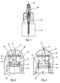
- the figure 1 is a schematic view of a dispensing device which comprises a reservoir 10 containing the fluid product to be dispensed, on which is assembled a dispensing member, in this case a pump 20, actuated by a pusher or dispensing head provided with a spray orifice 31.
- the dispensing head is of the nasal type and comprises a body 30 provided with an axial extension whose end is provided with the spray orifice 31, said axial extension being intended to penetrate into the nostril of the user.
- the dispenser member 20 may be a pump of a different type, or even a valve.
- the head of distribution may be of different shape, including a spray orifice 31 directed in a direction other than the axial direction shown on the figure 1 , and in particular in a direction approximately perpendicular to this axial direction, as shown in FIG. figure 4 .
- the dispensing head comprises upstream of the spray orifice 31 a spray profile, generally formed of non-radial channels connecting the expulsion channel of the head to a central swirl chamber. arranged directly upstream of the spray orifice.
- a spray profile generally formed of non-radial channels connecting the expulsion channel of the head to a central swirl chamber.
- Such a spraying profile induces significant shear stresses of the fluid product by a succession of contractions / detents, especially at the level of the non-radial channels and the swirl chamber.
- the present invention provides for replacing this spray pattern with a system more adapted to use with biological active principles, such as proteins, peptides, hormones, enzymes or the like, while guaranteeing a perfect spraying of said active principles. organic.
- the present invention aims to provide fluid dispensing devices capable of satisfying a certain number of spray performance, especially in terms of the size of the particles of the spray, which are preferably between 20 and 40 ⁇ m. .
- no particle will have a particle size of less than 10 ⁇ m.
- the spray speed is preferably less than 10 m / s, and ideally about 1 m / s.
- the spray angle that is to say the angle within which the different particles of the spray will be found after the exit through the spray orifice 31, is preferably less than 50 °, and advantageously about 30 °.
- the combination of these performances is particularly suitable for the distribution of biological active principles, the molecules of which have significant three-dimensional sizes relatively fragile and therefore subject to destruction in conventional spray profiles.
- these characteristics are applied at doses of 50 to 100 microliters of fluid, and the nasal head is preferably inserted into the nostril on a depth of about 1 centimeter.
- these values are not limiting but only given by way of example.
- the present invention provides means for generating vibration 40, 140, 240 in the hollow body 30, 130, 230 of the dispensing head, said means for generating vibrations being actuated at the moment of passage of the fluid product from the dispensing member 20, in this case preferably a mechanical pump, the actuation of said vibration generating means for finely spraying said fluid product through said spray orifice 31 , 131, 231. It is therefore the vibration generating means that undergo high frequency stresses that make it possible to spray the fluid product, the latter no longer undergoing the stresses, in particular shear stresses, of conventional spraying profiles.
- the vibration generating means 40 comprise a needle 41.
- This needle 41 is preferably associated with a piezoelectric plate 48 connected to a power source 49, the excitation of the piezoelectric plate 48 causing a
- the needle 41 has in its downstream end a point 45 adapted to seal the spray orifice 31 of the dispensing head when it is in the closed position.
- this closure in the closed position is made by cooperation with a membrane 39 disposed directly upstream of said spray orifice 31, as shown in FIGS. Figures 2 and 3 .
- the needle 41 slides preferably in a substantially cylindrical channel formed inside the body 30 of the dispensing head, this channel extending between the inlet orifice 32 and the spray orifice 31.
- inlet and spray port are found axially along a longitudinal axis A and said needle moves and vibrates along the same axis A.
- the needle 41 has in its upstream portion a disk 46 fixed on said piezoelectric plate 48 , and whose outer diameter is substantially equal to the inner diameter of said cylinder in which the needle moves.
- said needle 41 isolates a spray chamber 35, said tip 45 of the needle sealing the spray orifice 31, and said rear plate 46 of said needle closing a fluid passage 37 made in the body 30 of said dispensing head.
- said fluid product passage 37 is advantageously made in a side wall of said head, by a portion of greater diameter, so that in the open position shown on the figure 3 , the fluid product can flow laterally around said needle 41, in particular around said piezoelectric plate 48 and said disk 46, as symbolized by the arrows F on the figure 3 .
- the vibration of the needle 41 will cause the distribution of fine spray droplets from the fluid product arriving in said spray chamber 35, without exerting negative stresses on the fluid, which makes the device suitable to the distribution of biological active ingredients.
- the figure 4 represents a second embodiment of the present invention.
- the vibration generating means 140 comprise a vibrating plate 148 disposed on an inner wall of the body 130 of said dispensing head.
- the fluid product from the pump 20, preferably in the form of a gel, impinges on said vibrating plate 148, and the vibration of this vibrating plate 148 will cause the spraying into fine spray droplets of said fluid product, which will then be dispensed through said spray orifice 131.
- the spray orifice is oriented approximately perpendicular to the central axis of the head which corresponds to the direction of movement of the fluid, in particular through the inlet orifice 132, as symbolized by the arrows F.
- the vibrating plate 148 is preferably arranged in an inclined plane, advantageously at around 45 °, with respect to the direction F, to automatically and directly direct the droplets of fluid product towards the spray orifice 131.
- vibrating plate 148 is from preferably formed by a piezoelectric material, connected to a power supply 149, which is only very schematically represented on the figure 4 and which can be of any suitable form.
- a spray chamber 135 is formed directly upstream of the spray orifice 131, said vibrating plate 148 forming a wall of said spray chamber 135.
- Said chamber also comprises a fluid product inlet passage 137, preferably formed by a portion of reduced diameter in the body 130 of the dispensing head. The presence of this chamber between the vibrating plate 148 and the spray orifice 131 promotes the formation of the spray.
- the figure 5 represents a third embodiment of the present invention.
- the vibration generating means 240 comprise a vibrating membrane 241 disposed inside the body 230 of said dispensing head.
- This third embodiment in fact provides for forming a Helmholtz resonator directly upstream of the spray orifice 231, in order to guarantee the spraying of the jet of liquid coming from the pump.
- This Helmholtz resonator is advantageously formed by a substantially cylindrical resonance chamber 235 having a length L and a diameter D. Said resonance chamber 235 opens on its downstream side into the spray orifice 231 and comprises, on the opposite side, said membrane The diameter of this vibrating membrane is preferably substantially equal to the diameter D of the resonance chamber 235.
- the dimensions of length L and diameter D of the resonator are of course chosen to be smaller than the wavelengths. involved, in particular those of resonance of the vibrating membrane 241, as is typical for a Helmholtz resonator.
- this Helmholtz resonator in particular the volume of the resonance chamber 235, has the role of a hydraulic spring which pumps the liquid and contributes to the splitting of the spray at the spray orifice 231, without imposing constraints. shear or other excessive mechanical and physical stresses on the fluid product, making this device particularly suitable for the distribution of biological active principles.
- the dispensing head comprises a portion of larger diameter 237 forming a passage for the fluid product radially outside said vibrating membrane 241. The flow of fluid at this location is symbolized by the arrows F.
Description
La présente invention concerne un dispositif de distribution de produit fluide comportant une tête de distribution.The present invention relates to a fluid dispenser device comprising a dispensing head.
Plus particulièrement, la présente invention concerne des dispositifs de distribution de produit fluide adaptés pour distribuer ou pulvériser des doses de principes actifs biologiques, tel que par exemple des protéines, des peptides, des hormones, des enzymes ou similaires. En particulier, cette distribution peut être réalisée sous forme de spray nasal. Les dispositifs de distribution de produit fluide utilisés jusqu'à ce jour dans l'industrie pharmaceutique comportent de manière connue généralement un réservoir sur lequel est monté une pompe ou une valve qui est actionnée au moyen d'un poussoir ou tête de distribution pourvue d'un orifice de pulvérisation. Ces dispositifs qui sont parfaitement adaptés pour distribuer du produit liquide classique dans l'industrie pharmaceutique, s'avèrent plus difficiles à utiliser pour distribuer des principes actifs biologiques tel que les protéines, peptides, hormones, enzymes ou similaires. En particulier, les caractéristiques mécaniques et fluidiques fournies par les pompes ou les valves, et notamment les pertes de charge, les niveaux de turbulence et les contraintes de cisaillement, se sont généralement avérées incompatibles avec la structure moléculaire tridimensionnelle desdits principes actifs biologiques. Il s'ensuit que ces principes actifs biologiques sont généralement détériorés lors de la distribution à travers des dispositifs de distribution classiques, en particulier dans les profils de pulvérisation.More particularly, the present invention relates to fluid dispensing devices adapted for dispensing or spraying doses of biological active ingredients, such as, for example, proteins, peptides, hormones, enzymes or the like. In particular, this distribution can be performed as a nasal spray. Fluid dispensing devices used to date in the pharmaceutical industry generally include a tank on which is mounted a pump or a valve which is actuated by means of a pusher or dispensing head provided with a spray orifice. These devices which are perfectly adapted for dispensing conventional liquid product in the pharmaceutical industry, prove to be more difficult to use for dispensing biological active ingredients such as proteins, peptides, hormones, enzymes or the like. In particular, the mechanical and fluidic characteristics provided by the pumps or the valves, and in particular the pressure drops, the turbulence levels and the shear stresses, have generally been found to be incompatible with the three-dimensional molecular structure of said biological active principles. It follows that these biological active principles are generally deteriorated during distribution through conventional dispensing devices, in particular in the spray profiles.
Les documents
La présente invention a pour but de fournir un dispositif de distribution de produit fluide comportant une tête de distribution qui ne reproduit pas les inconvénients susmentionnés.The present invention aims to provide a fluid dispensing device comprising a dispensing head that does not reproduce the aforementioned drawbacks.
Plus particulièrement, la présente invention a pour but de fournir un dispositif de distribution adapté pour distribuer des principes actifs biologiques sans les détériorer de manière négative.More particularly, the present invention aims to provide a dispensing device adapted to distribute biological active ingredients without damaging them in a negative manner.
La présente invention a aussi pour but de fournir un tel dispositif de distribution de produit fluide adapté à fournir des performances de spray compatibles avec la nature des principes actifs biologiques tel que les protéines, les peptides, les hormones, les enzymes ou similaires.The present invention also aims to provide such a fluid dispenser device adapted to provide spray performance compatible with the nature of biological active principles such as proteins, peptides, hormones, enzymes or the like.
La présente invention a également pour but de fournir un tel dispositif de distribution de produit fluide qui soit simple et peu coûteux à fabriquer et à assembler.The present invention also aims to provide such a fluid dispenser device that is simple and inexpensive to manufacture and assemble.
La présente invention a donc pour objet un dispositif de distribution de produit fluide , comportant un réservoir contenant du produit fluide, un organe de distribution, tel qu'une pompe ou une valve, monté sur ledit réservoir, et une tête de distribution montée sur ledit organe de distribution, ladite tête de distribution comprenant un corps creux, définissant un passage de produit fluide entre un orifice d'entrée, relié audit organe de distribution, et un orifice de pulvérisation, des moyens de génération de vibrations étant disposés dans ledit passage en amont dudit orifice de pulvérisation, lesdits moyens de génération de vibrations étant actionnés lors du passage du produit fluide pour finement pulvériser ledit produit fluide à travers ledit orifice de pulvérisation.The present invention therefore relates to a fluid dispenser device, comprising a reservoir containing fluid, a dispensing member, such as a pump or a valve, mounted on said reservoir, and a dispensing head mounted on said dispensing member, said dispensing head comprising a hollow body, defining a fluid product passage between an inlet orifice, connected to said dispenser member, and a spray orifice, vibration generating means being disposed in said passage; upstream of said spray orifice, said vibration generating means being actuated during the passage of the fluid to finely spray said fluid through said spray orifice.
Avantageusement, lesdits moyens de génération de vibrations comportent un matériau piézoélectrique.Advantageously, said vibration generating means comprise a piezoelectric material.
Selon un premier mode de réalisation avantageux, lesdits moyens de génération de vibrations comportent un pointeau vibrant comportant une pointe adaptée à obturer ledit orifice de pulvérisation dans une position de fermeture.According to a first advantageous embodiment, said vibration generating means comprise a vibrating needle having a tip adapted to close said spray orifice in a closed position.
Avantageusement, ledit orifice d'entrée et ledit orifice de pulvérisation sont orientés axialement le long d'un axe longitudinal de ladite tête, ledit pointeau étant déplaçable et vibrant selon ledit axe longitudinal.Advantageously, said inlet orifice and said spray orifice are oriented axially along a longitudinal axis of said head, said needle being displaceable and vibrating along said longitudinal axis.
Avantageusement, en position de fermeture, ladite pointe coopère de manière étanche avec une membrane d'étanchéité disposée directement en amont dudit orifice de pulvérisation.Advantageously, in the closed position, said tip cooperates sealingly with a sealing membrane disposed directly upstream of said spray orifice.
Avantageusement, ledit pointeau est fixé sur une plaque piézoélectrique.Advantageously, said needle is fixed on a piezoelectric plate.
Avantageusement, ledit pointeau est déplaçable axialement dans ladite tête entre une position de fermeture, dans laquelle il obture l'orifice de pulvérisation et un passage de produit fluide, définissant ainsi une chambre de pulvérisation, et une position ouverte, dans laquelle il ouvre ledit orifice de pulvérisation et ledit passage de produit fluide, permettant au produit fluide de passer dudit orifice d'entrée vers ledit orifice de pulvérisation.Advantageously, said needle is axially displaceable in said head between a closed position, in which it closes the spray orifice and a fluid product passage, thus defining a spray chamber, and an open position, in which it opens said orifice spraying medium and said fluid product passage, allowing the fluid product to pass from said inlet port to said spray orifice.
Avantageusement, ledit passage de produit fluide est formé par une partie de plus grand diamètre réalisé à l'intérieur de ladite tête de distribution.Advantageously, said passage of fluid product is formed by a portion of larger diameter made inside said dispensing head.
Selon un second mode de réalisation avantageux, lesdits moyens de génération de vibrations comportent une plaque vibrante disposée sur une paroi interne de ladite tête, le produit fluide impactant ladite plaque vibrante.According to a second advantageous embodiment, said vibration generating means comprise a vibrating plate disposed on an inner wall of said head, the fluid product impacting said vibrating plate.
Avantageusement, ledit orifice de sortie est orienté environ perpendiculairement à la direction d'écoulement du produit fluide à travers l'orifice d'entrée, ladite plaque vibrante étant disposée sur une paroi interne inclinée, de préférence à environ 45°, de sorte que le jet de produit fluide impactant ladite plaque vibrante est fragmenté en spray et dirigé vers l'orifice de pulvérisation.Advantageously, said outlet orifice is oriented approximately perpendicular to the direction of flow of the fluid product through the inlet orifice, said vibrating plate being disposed on an inclined inner wall, preferably at approximately 45 °, so that the fluid jet impacting said vibrating plate is fragmented into spray and directed to the spray orifice.
Avantageusement, ladite plaque vibrante forme une paroi d'une chambre de pulvérisation comportant une entrée de chambre reliée audit orifice d'entrée et pourvue dudit orifice de pulvérisation.Advantageously, said vibrating plate forms a wall of a spray chamber comprising a chamber inlet connected to said inlet orifice and provided with said spray orifice.
Selon un troisième mode de réalisation avantageux, lesdits moyens de génération de vibrations comportent une membrane vibrante définissant entre ladite membrane vibrante et l'orifice de pulvérisation une chambre de résonance.According to a third advantageous embodiment, said vibration generating means comprise a vibrating membrane defining between said vibrating membrane and the spray orifice a resonance chamber.
Avantageusement, ladite chambre de résonance est sensiblement en forme de cylindre ayant une longueur et un diamètre inférieurs aux longueurs d'ondes de résonances de ladite membrane, ladite chambre de résonance formant un résonateur de Helmholtz.Advantageously, said resonance chamber is substantially cylinder-shaped having a length and a diameter smaller than the resonance wavelengths of said membrane, said resonance chamber forming a Helmholtz resonator.
Avantageusement, ladite membrane a sensiblement le même diamètre que ladite chambre de résonance, ladite tête comportant un passage pour le produit fluide s'étendant radialement à l'extérieur de ladite membrane.Advantageously, said membrane has substantially the same diameter as said resonance chamber, said head comprising a passage for the fluid product extending radially outside said membrane.
Avantageusement, le spray de produit fluide pulvérisé à travers ledit orifice de pulvérisation comporte une taille de particule moyenne comprise entre 20 et 40 µm et/ou une vitesse de spray inférieure à 10 m/s, avantageusement inférieure à 5 m/s, de préférence environ 1 m/s, et/ou un angle de spray inférieur à 50°, avantageusement environ 30°.Advantageously, the fluid spray sprayed through said spray orifice has an average particle size of between 20 and 40 μm and / or a spray speed of less than 10 m / s, advantageously less than 5 m / s, preferably about 1 m / s, and / or a spray angle of less than 50 °, preferably about 30 °.
Ces caractéristiques et avantages et d'autres de la présente invention apparaîtront plus clairement au cours de la description détaillée suivante de trois modes de réalisation de la présente invention, faite en référence aux dessins joints, donnés à titre d'exemples non limitatifs, et sur lesquels
- la
figure 1 est une vue schématique en section transversale d'un dispositif de distribution de produit fluide auquel la présente invention peut s'appliquer, - la
figure 2 est une vue schématique de détail en section transversale d'une partie d'une tête de distribution de produit fluide selon un premier mode de réalisation de la présente invention, en position de fermeture, - la
figure 3 est une vue similaire à celle de lafigure 2 , en position d'ouverture, - la
figure 4 est une vue similaire à celle desfigures 2 et 3 , représentant un second mode de réalisation de la présente invention, - la
figure 5 est une vue similaire auxfigures 2, 3 et4 , représentant un troisième mode de réalisation de la présente invention.
- the
figure 1 is a schematic cross-sectional view of a fluid dispenser device to which the present invention is applicable, - the
figure 2 is a diagrammatic cross-sectional detail view of a portion of a fluid dispenser head according to a first embodiment of the present invention, in the closed position, - the
figure 3 is a view similar to that of thefigure 2 , in the open position, - the
figure 4 is a view similar to that ofFigures 2 and 3 , representing a second embodiment of the present invention, - the
figure 5 is a view similar toFigures 2, 3 and4 , showing a third embodiment of the present invention.
La
Dans un dispositif de distribution de produit fluide classique, la tête de distribution comporte en amont de l'orifice de pulvérisation 31 un profil de pulvérisation, généralement formé de canaux non radiaux reliant le canal d'expulsion de la tête à une chambre de tourbillonnement centrale disposée directement en amont de l'orifice de pulvérisation. Un tel profil de pulvérisation induit des contraintes de cisaillement importantes du produit fluide par succession de contractions/détentes, notamment au niveau des canaux non radiaux et de la chambre de tourbillonnement.In a conventional fluid dispensing device, the dispensing head comprises upstream of the spray orifice 31 a spray profile, generally formed of non-radial channels connecting the expulsion channel of the head to a central swirl chamber. arranged directly upstream of the spray orifice. Such a spraying profile induces significant shear stresses of the fluid product by a succession of contractions / detents, especially at the level of the non-radial channels and the swirl chamber.
La présente invention prévoit de remplacer ce profil de pulvérisation par un système plus adapté à l'utilisation avec des principes actifs biologiques, tels que des protéines, des peptides, des hormones, des enzymes ou similaires, tout en garantissant une parfaite pulvérisation desdits principes actifs biologiques. En particulier, la présente invention a pour but de fournir les dispositifs de distribution de produit fluide capables de satisfaire un certain nombre de performances de spray, notamment au niveau de la taille des particules du spray, qui sont de préférence comprises entre 20 et 40 µm. Avantageusement, aucune particule n'aura une taille de particule inférieure à 10 µm. Par ailleurs, la vitesse de spray est de préférence inférieure à 10 m/s, et idéalement d'environ 1 m/s. L'angle de spray, c'est-à-dire l'angle à l'intérieur duquel se retrouveront les différentes particules du spray après la sortie à travers l'orifice de pulvérisation 31, est de préférence inférieur à 50°, et avantageusement environ de 30°. La combinaison de ces performances s'avère particulièrement adaptée à la distribution de principes actifs biologiques, dont les molécules ont des tailles tridimensionnelles importantes relativement fragiles et donc soumises à destruction dans les profils de pulvérisation classiques. Avantageusement, ces caractéristiques sont appliquées à des doses de 50 à 100 microlitres de produit fluide, et la tête nasale est de préférence insérée dans la narine sur une profondeur d'environ 1 centimètre. Bien entendu, ces valeurs ne sont pas limitatives mais seulement données à titre d'exemple.The present invention provides for replacing this spray pattern with a system more adapted to use with biological active principles, such as proteins, peptides, hormones, enzymes or the like, while guaranteeing a perfect spraying of said active principles. organic. In particular, the present invention aims to provide fluid dispensing devices capable of satisfying a certain number of spray performance, especially in terms of the size of the particles of the spray, which are preferably between 20 and 40 μm. . Advantageously, no particle will have a particle size of less than 10 μm. Furthermore, the spray speed is preferably less than 10 m / s, and ideally about 1 m / s. The spray angle, that is to say the angle within which the different particles of the spray will be found after the exit through the
Pour garantir l'obtention de ces caractéristiques ou performances de spray, la présente invention prévoit des moyens de génération de vibration 40, 140, 240 dans le corps creux 30, 130, 230 de la tête de distribution, lesdits moyens de génération de vibrations étant actionnés au moment du passage du produit fluide issu de l'organe de distribution 20, en l'occurrence de préférence une pompe mécanique, l'actionnement desdits moyens de génération de vibrations permettant de finement pulvériser ledit produit fluide à travers ledit orifice de pulvérisation 31, 131, 231. Ce sont donc les moyens de génération de vibrations qui subissent des contraintes haute fréquences qui permettent de pulvériser le produit fluide, celui-ci ne subissant plus les contraintes, notamment de cisaillement, des profils de pulvérisations classiques.In order to guarantee obtaining these characteristics or spray performance, the present invention provides means for generating
Les
La
La
Bien que la présente invention a été décrite et représentée en référence à trois modes de réalisation de celle-ci, il est entendu qu'elle n'est pas limitée à ces modes de réalisation, mais qu'au contraire un homme du métier peut y apporter toutes modifications utiles sans sortir du cadre de la présente invention, tel que définit par les revendications annexées.Although the present invention has been described and shown with reference to three embodiments thereof, it is understood that it is not limited to these embodiments, but that on the contrary a person skilled in the art can make any useful modifications without departing from the scope of the present invention, as defined by the appended claims.
Claims (15)
- A fluid dispenser device comprising: a reservoir (10) containing fluid; a dispenser member (20), such as a pump or a valve, that is mounted on said reservoir (10); and a dispenser head that is mounted on said dispenser member (20), said dispenser head including a hollow body (30, 130, 230) that defines a fluid passage between an inlet orifice (32, 132, 232), connected to said dispenser member (20), and a spray orifice (31, 131, 231); the device being characterized in that vibration generator means (40, 140, 240) are arranged in said passage upstream from said spray orifice (31, 131, 231), said vibration generator means (40, 140, 240) being actuated while fluid is passing so as to spray said fluid finely through said spray orifice (31, 131, 231).
- A device according to claim 1, wherein said vibration generator means (40, 140, 240) include a piezoelectric material.
- A device according to claim 1 or claim 2, wherein said vibration generator means (40) include a vibrating pin (41) that includes a tip (45) that is adapted to plug said spray orifice (31) in a closed position.
- A device according to claim 3, wherein said inlet orifice (32) and said spray orifice (31) are oriented axially along a longitudinal axis (A) of said head, said pin (41) being movable and vibrating along said longitudinal axis (A).
- A device according to claim 3 or claim 4, wherein, in the closed position, said tip (45) co-operates in leaktight manner with a sealing diaphragm (39) that is arranged directly upstream from said spray orifice (31).
- A device according to any one of claims 3 to 5, wherein said pin (41) is fastened on a piezoelectric plate (48).
- A device according to any one of claims 3 to 6, wherein said pin (41) is axially movable in said head between a closed position in which it plugs the spray orifice (31) and a fluid passage (37), thereby defining a spray chamber (35), and an open position in which it opens said spray orifice (31) and said fluid passage (37), enabling the fluid to pass from said inlet orifice (32) to said spray orifice (31).
- A device according to claim 7, wherein said fluid passage (37) is formed by a portion of greater diameter formed inside said dispenser head.
- A device according to claim 1 or claim 2, wherein said vibration generator means (140) comprise a vibrating plate (148) that is arranged on an inside wall of said head, the fluid impacting said vibrating plate (148).
- A device according to claim 9, wherein said outlet orifice (131) is oriented approximately perpendicularly to the direction of flow of the fluid (F) through the inlet orifice (132), said vibrating plate being arranged on an inside wall (138) that slopes, preferably at about 45°, so that the jet of fluid impacting said vibrating plate (148) is fragmented into spray and directed towards the spray orifice (131).
- A device according to claim 9 or claim 10, wherein said vibrating plate (148) forms a wall of a spray chamber (135) that includes a chamber inlet (137) connected to said inlet orifice (132), and that is provided with said spray orifice (131).
- A device according to claim 1 or claim 2, wherein said vibration generator means (240) comprise a vibrating diaphragm (241) that defines a resonance chamber (235) between said vibrating diaphragm (241) and the spray orifice (231).
- A device according to claim 12, wherein said resonance chamber (235) is substantially in the shape of a cylinder having a length (L) and a diameter (D) that are shorter than the resonance wavelengths of said diaphragm (241), said resonance chamber (235) forming a Helmholtz resonator.
- A device according to claim 13, wherein said diaphragm (241) has substantially the same diameter (D) as said resonance chamber (235), said head including a passage (237) for the fluid, which passage extends radially outside said diaphragm (241).
- A device according to any preceding claim, wherein the fluid spray that is sprayed through said spray orifice (31, 131, 231) has a mean particle size lying in the range 20 µm to 40 µm, and/or a spray speed that is less than 10 m/s, advantageously less than 5 m/s, preferably about 1 m/s, and/or a spray angle that is less than 50°, advantageously about 30°.
Applications Claiming Priority (2)
| Application Number | Priority Date | Filing Date | Title |
|---|---|---|---|
| FR0957337A FR2951442B1 (en) | 2009-10-20 | 2009-10-20 | DISPENSING HEAD FOR FLUID PRODUCT DISPENSING DEVICE. |
| PCT/FR2010/052235 WO2011048330A1 (en) | 2009-10-20 | 2010-10-20 | Distribution head for a device for distributing a fluid product |
Publications (2)
| Publication Number | Publication Date |
|---|---|
| EP2490823A1 EP2490823A1 (en) | 2012-08-29 |
| EP2490823B1 true EP2490823B1 (en) | 2014-12-17 |
Family
ID=42112217
Family Applications (1)
| Application Number | Title | Priority Date | Filing Date |
|---|---|---|---|
| EP10785482.0A Active EP2490823B1 (en) | 2009-10-20 | 2010-10-20 | Dispensing head for a fluid dispenser |
Country Status (7)
| Country | Link |
|---|---|
| US (1) | US9387975B2 (en) |
| EP (1) | EP2490823B1 (en) |
| JP (1) | JP2013508051A (en) |
| CN (1) | CN102548667A (en) |
| FR (1) | FR2951442B1 (en) |
| IN (1) | IN2012DN02113A (en) |
| WO (1) | WO2011048330A1 (en) |
Families Citing this family (8)
| Publication number | Priority date | Publication date | Assignee | Title |
|---|---|---|---|---|
| DE202011107265U1 (en) * | 2011-10-31 | 2013-02-11 | Nordson Corporation | Dispensing module, applicator head and nozzle for dispensing a fluid, in particular hot melt adhesive |
| WO2014165694A2 (en) * | 2013-04-04 | 2014-10-09 | The United States Of America, As Represented By The Secretary, Department Of Health And Human Services, Centers For Disease Control Aned Prevention | Nasal aerosol delivery system |
| JP6322844B2 (en) * | 2014-06-25 | 2018-05-16 | 東興薬品工業株式会社 | Nasal spray nozzle used for medical syringes |
| KR102491446B1 (en) | 2014-06-25 | 2023-01-20 | 도코 야쿠힌 고교 가부시키가이샤 | Rhinovaccination system of influenza vaccine |
| CN107430101B (en) * | 2015-03-31 | 2021-07-16 | 沃特世科技公司 | Multi-injection mode valve module |
| IT201600080879A1 (en) * | 2016-08-01 | 2018-02-01 | Giorgio Mezzoli | REGULATOR |
| CN108787192B (en) * | 2017-05-02 | 2020-07-17 | 苏州众慧合智能制造有限公司 | Self-excitation pulse type energy-saving valve |
| JP2022521471A (en) * | 2019-02-08 | 2022-04-08 | レッキニ,ヒュリヤ トパル | Fluid dispenser for distributing cosmetics |
Citations (2)
| Publication number | Priority date | Publication date | Assignee | Title |
|---|---|---|---|---|
| US3739952A (en) * | 1971-07-09 | 1973-06-19 | Gillette Co | Intermittent dispensing device |
| US20050100512A1 (en) * | 2000-04-17 | 2005-05-12 | Daizo Corporation | Intermittent injection aerosol product for skin |
Family Cites Families (18)
| Publication number | Priority date | Publication date | Assignee | Title |
|---|---|---|---|---|
| US2766064A (en) * | 1955-08-22 | 1956-10-09 | Howard V Schweitzer | Paint gun |
| US3224677A (en) * | 1964-09-14 | 1965-12-21 | Kelroy Corp | Vaporizing apparatus |
| US5435282A (en) * | 1994-05-19 | 1995-07-25 | Habley Medical Technology Corporation | Nebulizer |
| JPH08332425A (en) * | 1995-06-06 | 1996-12-17 | Funai Electric Co Ltd | Atomizer |
| JPH08332426A (en) * | 1995-06-09 | 1996-12-17 | Funai Electric Co Ltd | Atomizer |
| DE19743299C2 (en) * | 1997-09-30 | 1999-11-18 | Siemens Ag | Device for controlling an actuator |
| DE10102846B4 (en) * | 2001-01-23 | 2012-04-12 | Pari Pharma Gmbh | aerosol generator |
| US8012136B2 (en) * | 2003-05-20 | 2011-09-06 | Optimyst Systems, Inc. | Ophthalmic fluid delivery device and method of operation |
| KR101149275B1 (en) * | 2004-02-24 | 2012-05-25 | 마이크로도스 테라퓨특스, 인코포레이티드 | Synthetic jet based medicament delivery method and apparatus |
| US9108211B2 (en) * | 2005-05-25 | 2015-08-18 | Nektar Therapeutics | Vibration systems and methods |
| KR100707211B1 (en) * | 2006-02-03 | 2007-04-13 | 삼성전자주식회사 | Synthetic jet actuator |
| CN2889333Y (en) * | 2006-05-24 | 2007-04-18 | 深圳市健康源科技有限公司 | Mouth sucking type household ultrasonic atomization therapeutic device |
| FR2908329B1 (en) * | 2006-11-14 | 2011-01-07 | Telemaq | DEVICE AND METHOD FOR ULTRASOUND FLUID DELIVERY |
| WO2008061408A1 (en) | 2006-11-22 | 2008-05-29 | Huiliang Liu | Flameless medical electronic atomizer |
| EP1927373B1 (en) * | 2006-11-30 | 2012-08-22 | PARI Pharma GmbH | Inhalation nebulizer |
| US20080128527A1 (en) * | 2006-12-05 | 2008-06-05 | The Hong Kong Polytechnic University | Liquid dispensing apparatus based on piezoelectrically driven hollow horn |
| US20090054116A1 (en) * | 2007-08-23 | 2009-02-26 | Nokia Corporation | Method and apparatus for scent dispensing |
| US20090108094A1 (en) * | 2007-10-23 | 2009-04-30 | Yehuda Ivri | Synthetic jet air freshener |
-
2009
- 2009-10-20 FR FR0957337A patent/FR2951442B1/en active Active
-
2010
- 2010-10-20 US US13/502,926 patent/US9387975B2/en active Active
- 2010-10-20 CN CN201080045569XA patent/CN102548667A/en active Pending
- 2010-10-20 JP JP2012534748A patent/JP2013508051A/en not_active Withdrawn
- 2010-10-20 EP EP10785482.0A patent/EP2490823B1/en active Active
- 2010-10-20 WO PCT/FR2010/052235 patent/WO2011048330A1/en active Application Filing
-
2012
- 2012-03-09 IN IN2113DEN2012 patent/IN2012DN02113A/en unknown
Patent Citations (2)
| Publication number | Priority date | Publication date | Assignee | Title |
|---|---|---|---|---|
| US3739952A (en) * | 1971-07-09 | 1973-06-19 | Gillette Co | Intermittent dispensing device |
| US20050100512A1 (en) * | 2000-04-17 | 2005-05-12 | Daizo Corporation | Intermittent injection aerosol product for skin |
Also Published As
| Publication number | Publication date |
|---|---|
| US20120205464A1 (en) | 2012-08-16 |
| FR2951442B1 (en) | 2012-01-20 |
| WO2011048330A1 (en) | 2011-04-28 |
| US9387975B2 (en) | 2016-07-12 |
| IN2012DN02113A (en) | 2015-08-21 |
| FR2951442A1 (en) | 2011-04-22 |
| EP2490823A1 (en) | 2012-08-29 |
| CN102548667A (en) | 2012-07-04 |
| JP2013508051A (en) | 2013-03-07 |
Similar Documents
| Publication | Publication Date | Title |
|---|---|---|
| EP2490823B1 (en) | Dispensing head for a fluid dispenser | |
| EP3121071B1 (en) | Device for cleaning a sensor for a motor vehicle | |
| EP1339501B1 (en) | Fluid or powdery product dispensing device | |
| FR2773784A1 (en) | Atomizer head for fluid product dispenser with outlet channel and spring-loaded shutter | |
| EP0802827A1 (en) | Spray nozzle | |
| FR2892158A1 (en) | FLUID PRODUCT DELIVERY PUMP | |
| FR2782024A1 (en) | DISPENSING HEAD AND DEVICE FOR DISPENSING A FLUID PRODUCT COMPRISING SUCH A HEAD | |
| FR3050125A1 (en) | SPRAY NOZZLE, IN PARTICULAR FOR A SYSTEM FOR DISTRIBUTING A PRESSED PRODUCT WITH A PUSH BUTTON, AND A DISTRIBUTION SYSTEM COMPRISING SUCH A NOZZLE | |
| EP0471610B1 (en) | Nozzle with incorporated valve | |
| FR2815611A1 (en) | Spray head has liquid channel which terminates in outlet and contains rigid insert, flexible tube fitting around upper end of this and being deformed when it is squeezed between insert and front wall of spray head, to allow spraying | |
| EP1446231B1 (en) | Dispensing head and fluid product dispenser comprising same | |
| FR3072313B1 (en) | DEVICE FOR DISPENSING FLUID PRODUCT | |
| EP1606192A1 (en) | Product distributor comprising a pump operated by a plunger | |
| FR3065890A1 (en) | FLUID PRODUCT DISTRIBUTION MODULE. | |
| EP0897324B1 (en) | Two-phase spray device for a fluid or pasty material | |
| EP2446970A1 (en) | Dispensing system and dispenser for a fluid product dispenser | |
| FR2838110A1 (en) | FLUID PRODUCT DISPENSING DEVICE | |
| EP3016706A1 (en) | Fluid or powdery product dispensing device | |
| EP1230031B1 (en) | Fast rate pump | |
| WO2003078073A1 (en) | Fluid product dispensing device | |
| WO2018041594A1 (en) | Pressurised fluid dispensing head and aerosol can or manual pump comprising such a dispensing head | |
| FR3079428A1 (en) | HEAD OF DISTRIBUTION OF FLUID PRODUCT. | |
| WO2020229762A1 (en) | Device for dispensing a fluid product | |
| FR3083997A1 (en) | PUMP FOR DISPENSING A FLUID PRODUCT, DISPENSING HEAD EQUIPPED WITH SUCH A PUMP AND BOTTLE THEREOF | |
| FR3117046A1 (en) | Powder dose dispensing device |
Legal Events
| Date | Code | Title | Description |
|---|---|---|---|
| PUAI | Public reference made under article 153(3) epc to a published international application that has entered the european phase |
Free format text: ORIGINAL CODE: 0009012 |
|
| 17P | Request for examination filed |
Effective date: 20120515 |
|
| AK | Designated contracting states |
Kind code of ref document: A1 Designated state(s): AL AT BE BG CH CY CZ DE DK EE ES FI FR GB GR HR HU IE IS IT LI LT LU LV MC MK MT NL NO PL PT RO RS SE SI SK SM TR |
|
| RAP1 | Party data changed (applicant data changed or rights of an application transferred) |
Owner name: APTAR FRANCE SAS |
|
| DAX | Request for extension of the european patent (deleted) | ||
| 17Q | First examination report despatched |
Effective date: 20130228 |
|
| REG | Reference to a national code |
Ref country code: DE Ref legal event code: R079 Ref document number: 602010021137 Country of ref document: DE Free format text: PREVIOUS MAIN CLASS: B05B0011000000 Ipc: B05B0017060000 |
|
| RIC1 | Information provided on ipc code assigned before grant |
Ipc: B05B 11/00 20060101ALN20140508BHEP Ipc: A61M 15/00 20060101ALI20140508BHEP Ipc: B05B 17/06 20060101AFI20140508BHEP Ipc: A61M 15/08 20060101ALI20140508BHEP Ipc: B65D 83/28 20060101ALI20140508BHEP |
|
| RIC1 | Information provided on ipc code assigned before grant |
Ipc: A61M 15/08 20060101ALI20140509BHEP Ipc: B05B 11/00 20060101ALN20140509BHEP Ipc: B05B 17/06 20060101AFI20140509BHEP Ipc: B65D 83/28 20060101ALI20140509BHEP Ipc: A61M 15/00 20060101ALI20140509BHEP |
|
| GRAP | Despatch of communication of intention to grant a patent |
Free format text: ORIGINAL CODE: EPIDOSNIGR1 |
|
| INTG | Intention to grant announced |
Effective date: 20140714 |
|
| GRAS | Grant fee paid |
Free format text: ORIGINAL CODE: EPIDOSNIGR3 |
|
| GRAA | (expected) grant |
Free format text: ORIGINAL CODE: 0009210 |
|
| AK | Designated contracting states |
Kind code of ref document: B1 Designated state(s): AL AT BE BG CH CY CZ DE DK EE ES FI FR GB GR HR HU IE IS IT LI LT LU LV MC MK MT NL NO PL PT RO RS SE SI SK SM TR |
|
| REG | Reference to a national code |
Ref country code: GB Ref legal event code: FG4D Free format text: NOT ENGLISH |
|
| REG | Reference to a national code |
Ref country code: CH Ref legal event code: EP |
|
| REG | Reference to a national code |
Ref country code: IE Ref legal event code: FG4D Free format text: LANGUAGE OF EP DOCUMENT: FRENCH |
|
| REG | Reference to a national code |
Ref country code: AT Ref legal event code: REF Ref document number: 701495 Country of ref document: AT Kind code of ref document: T Effective date: 20150115 |
|
| REG | Reference to a national code |
Ref country code: DE Ref legal event code: R096 Ref document number: 602010021137 Country of ref document: DE Effective date: 20150129 |
|
| PG25 | Lapsed in a contracting state [announced via postgrant information from national office to epo] |
Ref country code: NO Free format text: LAPSE BECAUSE OF FAILURE TO SUBMIT A TRANSLATION OF THE DESCRIPTION OR TO PAY THE FEE WITHIN THE PRESCRIBED TIME-LIMIT Effective date: 20150317 Ref country code: FI Free format text: LAPSE BECAUSE OF FAILURE TO SUBMIT A TRANSLATION OF THE DESCRIPTION OR TO PAY THE FEE WITHIN THE PRESCRIBED TIME-LIMIT Effective date: 20141217 Ref country code: LT Free format text: LAPSE BECAUSE OF FAILURE TO SUBMIT A TRANSLATION OF THE DESCRIPTION OR TO PAY THE FEE WITHIN THE PRESCRIBED TIME-LIMIT Effective date: 20141217 |
|
| REG | Reference to a national code |
Ref country code: LT Ref legal event code: MG4D |
|
| PG25 | Lapsed in a contracting state [announced via postgrant information from national office to epo] |
Ref country code: HR Free format text: LAPSE BECAUSE OF FAILURE TO SUBMIT A TRANSLATION OF THE DESCRIPTION OR TO PAY THE FEE WITHIN THE PRESCRIBED TIME-LIMIT Effective date: 20141217 Ref country code: SE Free format text: LAPSE BECAUSE OF FAILURE TO SUBMIT A TRANSLATION OF THE DESCRIPTION OR TO PAY THE FEE WITHIN THE PRESCRIBED TIME-LIMIT Effective date: 20141217 Ref country code: RS Free format text: LAPSE BECAUSE OF FAILURE TO SUBMIT A TRANSLATION OF THE DESCRIPTION OR TO PAY THE FEE WITHIN THE PRESCRIBED TIME-LIMIT Effective date: 20141217 Ref country code: GR Free format text: LAPSE BECAUSE OF FAILURE TO SUBMIT A TRANSLATION OF THE DESCRIPTION OR TO PAY THE FEE WITHIN THE PRESCRIBED TIME-LIMIT Effective date: 20150318 Ref country code: LV Free format text: LAPSE BECAUSE OF FAILURE TO SUBMIT A TRANSLATION OF THE DESCRIPTION OR TO PAY THE FEE WITHIN THE PRESCRIBED TIME-LIMIT Effective date: 20141217 |
|
| REG | Reference to a national code |
Ref country code: AT Ref legal event code: MK05 Ref document number: 701495 Country of ref document: AT Kind code of ref document: T Effective date: 20141217 |
|
| REG | Reference to a national code |
Ref country code: DE Ref legal event code: R082 Ref document number: 602010021137 Country of ref document: DE Representative=s name: STAUDT IP LAW, DE |
|
| PG25 | Lapsed in a contracting state [announced via postgrant information from national office to epo] |
Ref country code: NL Free format text: LAPSE BECAUSE OF FAILURE TO SUBMIT A TRANSLATION OF THE DESCRIPTION OR TO PAY THE FEE WITHIN THE PRESCRIBED TIME-LIMIT Effective date: 20141217 |
|
| PG25 | Lapsed in a contracting state [announced via postgrant information from national office to epo] |
Ref country code: SK Free format text: LAPSE BECAUSE OF FAILURE TO SUBMIT A TRANSLATION OF THE DESCRIPTION OR TO PAY THE FEE WITHIN THE PRESCRIBED TIME-LIMIT Effective date: 20141217 Ref country code: EE Free format text: LAPSE BECAUSE OF FAILURE TO SUBMIT A TRANSLATION OF THE DESCRIPTION OR TO PAY THE FEE WITHIN THE PRESCRIBED TIME-LIMIT Effective date: 20141217 Ref country code: RO Free format text: LAPSE BECAUSE OF FAILURE TO SUBMIT A TRANSLATION OF THE DESCRIPTION OR TO PAY THE FEE WITHIN THE PRESCRIBED TIME-LIMIT Effective date: 20141217 Ref country code: CZ Free format text: LAPSE BECAUSE OF FAILURE TO SUBMIT A TRANSLATION OF THE DESCRIPTION OR TO PAY THE FEE WITHIN THE PRESCRIBED TIME-LIMIT Effective date: 20141217 Ref country code: ES Free format text: LAPSE BECAUSE OF FAILURE TO SUBMIT A TRANSLATION OF THE DESCRIPTION OR TO PAY THE FEE WITHIN THE PRESCRIBED TIME-LIMIT Effective date: 20141217 |
|
| PG25 | Lapsed in a contracting state [announced via postgrant information from national office to epo] |
Ref country code: AT Free format text: LAPSE BECAUSE OF FAILURE TO SUBMIT A TRANSLATION OF THE DESCRIPTION OR TO PAY THE FEE WITHIN THE PRESCRIBED TIME-LIMIT Effective date: 20141217 Ref country code: IS Free format text: LAPSE BECAUSE OF FAILURE TO SUBMIT A TRANSLATION OF THE DESCRIPTION OR TO PAY THE FEE WITHIN THE PRESCRIBED TIME-LIMIT Effective date: 20150417 Ref country code: PL Free format text: LAPSE BECAUSE OF FAILURE TO SUBMIT A TRANSLATION OF THE DESCRIPTION OR TO PAY THE FEE WITHIN THE PRESCRIBED TIME-LIMIT Effective date: 20141217 |
|
| REG | Reference to a national code |
Ref country code: DE Ref legal event code: R097 Ref document number: 602010021137 Country of ref document: DE |
|
| PLBE | No opposition filed within time limit |
Free format text: ORIGINAL CODE: 0009261 |
|
| STAA | Information on the status of an ep patent application or granted ep patent |
Free format text: STATUS: NO OPPOSITION FILED WITHIN TIME LIMIT |
|
| REG | Reference to a national code |
Ref country code: FR Ref legal event code: PLFP Year of fee payment: 6 |
|
| PG25 | Lapsed in a contracting state [announced via postgrant information from national office to epo] |
Ref country code: DK Free format text: LAPSE BECAUSE OF FAILURE TO SUBMIT A TRANSLATION OF THE DESCRIPTION OR TO PAY THE FEE WITHIN THE PRESCRIBED TIME-LIMIT Effective date: 20141217 |
|
| 26N | No opposition filed |
Effective date: 20150918 |
|
| PG25 | Lapsed in a contracting state [announced via postgrant information from national office to epo] |
Ref country code: SI Free format text: LAPSE BECAUSE OF FAILURE TO SUBMIT A TRANSLATION OF THE DESCRIPTION OR TO PAY THE FEE WITHIN THE PRESCRIBED TIME-LIMIT Effective date: 20141217 |
|
| PG25 | Lapsed in a contracting state [announced via postgrant information from national office to epo] |
Ref country code: LU Free format text: LAPSE BECAUSE OF FAILURE TO SUBMIT A TRANSLATION OF THE DESCRIPTION OR TO PAY THE FEE WITHIN THE PRESCRIBED TIME-LIMIT Effective date: 20151020 |
|
| REG | Reference to a national code |
Ref country code: CH Ref legal event code: PL |
|
| PG25 | Lapsed in a contracting state [announced via postgrant information from national office to epo] |
Ref country code: MC Free format text: LAPSE BECAUSE OF FAILURE TO SUBMIT A TRANSLATION OF THE DESCRIPTION OR TO PAY THE FEE WITHIN THE PRESCRIBED TIME-LIMIT Effective date: 20141217 |
|
| REG | Reference to a national code |
Ref country code: IE Ref legal event code: MM4A |
|
| PG25 | Lapsed in a contracting state [announced via postgrant information from national office to epo] |
Ref country code: LI Free format text: LAPSE BECAUSE OF NON-PAYMENT OF DUE FEES Effective date: 20151031 Ref country code: CH Free format text: LAPSE BECAUSE OF NON-PAYMENT OF DUE FEES Effective date: 20151031 |
|
| REG | Reference to a national code |
Ref country code: FR Ref legal event code: PLFP Year of fee payment: 7 |
|
| PG25 | Lapsed in a contracting state [announced via postgrant information from national office to epo] |
Ref country code: IE Free format text: LAPSE BECAUSE OF NON-PAYMENT OF DUE FEES Effective date: 20151020 |
|
| PG25 | Lapsed in a contracting state [announced via postgrant information from national office to epo] |
Ref country code: SM Free format text: LAPSE BECAUSE OF FAILURE TO SUBMIT A TRANSLATION OF THE DESCRIPTION OR TO PAY THE FEE WITHIN THE PRESCRIBED TIME-LIMIT Effective date: 20141217 Ref country code: BG Free format text: LAPSE BECAUSE OF FAILURE TO SUBMIT A TRANSLATION OF THE DESCRIPTION OR TO PAY THE FEE WITHIN THE PRESCRIBED TIME-LIMIT Effective date: 20141217 Ref country code: HU Free format text: LAPSE BECAUSE OF FAILURE TO SUBMIT A TRANSLATION OF THE DESCRIPTION OR TO PAY THE FEE WITHIN THE PRESCRIBED TIME-LIMIT; INVALID AB INITIO Effective date: 20101020 |
|
| PG25 | Lapsed in a contracting state [announced via postgrant information from national office to epo] |
Ref country code: CY Free format text: LAPSE BECAUSE OF FAILURE TO SUBMIT A TRANSLATION OF THE DESCRIPTION OR TO PAY THE FEE WITHIN THE PRESCRIBED TIME-LIMIT Effective date: 20141217 |
|
| PG25 | Lapsed in a contracting state [announced via postgrant information from national office to epo] |
Ref country code: BE Free format text: LAPSE BECAUSE OF NON-PAYMENT OF DUE FEES Effective date: 20151031 |
|
| PG25 | Lapsed in a contracting state [announced via postgrant information from national office to epo] |
Ref country code: TR Free format text: LAPSE BECAUSE OF FAILURE TO SUBMIT A TRANSLATION OF THE DESCRIPTION OR TO PAY THE FEE WITHIN THE PRESCRIBED TIME-LIMIT Effective date: 20141217 Ref country code: MT Free format text: LAPSE BECAUSE OF FAILURE TO SUBMIT A TRANSLATION OF THE DESCRIPTION OR TO PAY THE FEE WITHIN THE PRESCRIBED TIME-LIMIT Effective date: 20141217 |
|
| REG | Reference to a national code |
Ref country code: FR Ref legal event code: PLFP Year of fee payment: 8 |
|
| PG25 | Lapsed in a contracting state [announced via postgrant information from national office to epo] |
Ref country code: MK Free format text: LAPSE BECAUSE OF FAILURE TO SUBMIT A TRANSLATION OF THE DESCRIPTION OR TO PAY THE FEE WITHIN THE PRESCRIBED TIME-LIMIT Effective date: 20141217 |
|
| PG25 | Lapsed in a contracting state [announced via postgrant information from national office to epo] |
Ref country code: PT Free format text: LAPSE BECAUSE OF FAILURE TO SUBMIT A TRANSLATION OF THE DESCRIPTION OR TO PAY THE FEE WITHIN THE PRESCRIBED TIME-LIMIT Effective date: 20141217 |
|
| REG | Reference to a national code |
Ref country code: FR Ref legal event code: PLFP Year of fee payment: 9 |
|
| PG25 | Lapsed in a contracting state [announced via postgrant information from national office to epo] |
Ref country code: AL Free format text: LAPSE BECAUSE OF FAILURE TO SUBMIT A TRANSLATION OF THE DESCRIPTION OR TO PAY THE FEE WITHIN THE PRESCRIBED TIME-LIMIT Effective date: 20141217 |
|
| P01 | Opt-out of the competence of the unified patent court (upc) registered |
Effective date: 20230526 |
|
| PGFP | Annual fee paid to national office [announced via postgrant information from national office to epo] |
Ref country code: GB Payment date: 20231120 Year of fee payment: 14 |
|
| REG | Reference to a national code |
Ref country code: DE Ref legal event code: R082 Ref document number: 602010021137 Country of ref document: DE Representative=s name: SONNENBERG HARRISON PARTNERSCHAFT MBB PATENT- , DE |
|
| PGFP | Annual fee paid to national office [announced via postgrant information from national office to epo] |
Ref country code: IT Payment date: 20231011 Year of fee payment: 14 Ref country code: FR Payment date: 20231027 Year of fee payment: 14 Ref country code: DE Payment date: 20231107 Year of fee payment: 14 |