EP2490597B1 - Speculum - Google Patents
Speculum Download PDFInfo
- Publication number
- EP2490597B1 EP2490597B1 EP10770934.7A EP10770934A EP2490597B1 EP 2490597 B1 EP2490597 B1 EP 2490597B1 EP 10770934 A EP10770934 A EP 10770934A EP 2490597 B1 EP2490597 B1 EP 2490597B1
- Authority
- EP
- European Patent Office
- Prior art keywords
- speculum
- arms
- elements
- arm
- channel
- Prior art date
- Legal status (The legal status is an assumption and is not a legal conclusion. Google has not performed a legal analysis and makes no representation as to the accuracy of the status listed.)
- Active
Links
- 210000000744 eyelid Anatomy 0.000 claims description 20
- 230000002452 interceptive effect Effects 0.000 claims description 4
- 238000000465 moulding Methods 0.000 claims description 4
- 230000000670 limiting effect Effects 0.000 claims description 2
- 230000014759 maintenance of location Effects 0.000 claims 2
- 229920001169 thermoplastic Polymers 0.000 claims 1
- 239000004416 thermosoftening plastic Substances 0.000 claims 1
- 238000000926 separation method Methods 0.000 description 8
- 210000003811 finger Anatomy 0.000 description 7
- 238000004519 manufacturing process Methods 0.000 description 4
- 238000000034 method Methods 0.000 description 4
- 230000000717 retained effect Effects 0.000 description 3
- 238000001746 injection moulding Methods 0.000 description 2
- 238000001356 surgical procedure Methods 0.000 description 2
- 239000012815 thermoplastic material Substances 0.000 description 2
- 230000000295 complement effect Effects 0.000 description 1
- 210000005224 forefinger Anatomy 0.000 description 1
- 210000003128 head Anatomy 0.000 description 1
- 239000000463 material Substances 0.000 description 1
- 230000036961 partial effect Effects 0.000 description 1
- 230000005855 radiation Effects 0.000 description 1
- 230000002829 reductive effect Effects 0.000 description 1
- 230000000284 resting effect Effects 0.000 description 1
- 230000002441 reversible effect Effects 0.000 description 1
- 230000001954 sterilising effect Effects 0.000 description 1
- 238000004659 sterilization and disinfection Methods 0.000 description 1
- 210000003813 thumb Anatomy 0.000 description 1
Images


Classifications
-
- A—HUMAN NECESSITIES
- A61—MEDICAL OR VETERINARY SCIENCE; HYGIENE
- A61B—DIAGNOSIS; SURGERY; IDENTIFICATION
- A61B17/00—Surgical instruments, devices or methods, e.g. tourniquets
- A61B17/02—Surgical instruments, devices or methods, e.g. tourniquets for holding wounds open; Tractors
- A61B17/0231—Surgical instruments, devices or methods, e.g. tourniquets for holding wounds open; Tractors for eye surgery
-
- A—HUMAN NECESSITIES
- A61—MEDICAL OR VETERINARY SCIENCE; HYGIENE
- A61B—DIAGNOSIS; SURGERY; IDENTIFICATION
- A61B17/00—Surgical instruments, devices or methods, e.g. tourniquets
- A61B17/28—Surgical forceps
- A61B17/2812—Surgical forceps with a single pivotal connection
- A61B17/2816—Pivots
-
- A—HUMAN NECESSITIES
- A61—MEDICAL OR VETERINARY SCIENCE; HYGIENE
- A61B—DIAGNOSIS; SURGERY; IDENTIFICATION
- A61B17/00—Surgical instruments, devices or methods, e.g. tourniquets
- A61B17/28—Surgical forceps
- A61B17/2812—Surgical forceps with a single pivotal connection
- A61B17/2833—Locking means
Definitions
- This invention relates to speculums for opening, and maintaining in an open position, eyelids, and, more particular, to speculums having arrangements for being retained at specific open positions.
- Speculums are know in the prior art for opening, and maintaining in an open position, eyelids during ocular procedures or surgery.
- Prior art speculums include bent-wire speculums where the speculum is formed from a unitary piece of resilient wire. The speculums are provided in unbiased, rest states, corresponding to the open position of the eyelids. For use, the speculums are compressed to engage the eyelids and, then, allowed to expand to cause opening thereof. These speculums have no provision for positional adjustment or being retained at a particular position. The inherently generated elastic force is used to maintain these speculums during use.
- speculums have been also provided in the prior art with separate positional adjustment arrangements.
- speculums have been provided which include a bolt spanning between the arms of the speculum, wherein threaded movement of a nut along the length of the bolt causes positional adjustment of one or both of the arms.
- These speculums require components in addition to the speculum itself.
- a speculum according to claim 1 or 13 includes a first arm having a first channel formed thereon adapted to the shape of an eyelid; a second arm having a second channel formed thereon adapted to the shape of an eyelid; a hinge unitarily formed with the first and second arms, the hinge permitting the first and second arms to selectively rotate about an axis rotation, the selective rotation causing the first and second channels to selectively move closer and farther apart; and, a position retaining arrangement.
- the position retaining arrangement includes a first element formed unitarily with the first arm, and a second element formed unitarily with the second arm. The first and second elements are configured to cooperatively retain the first and second arms in a selected rotational position.
- a unitary speculum may be formed which includes an adjustable position retaining arrangement.
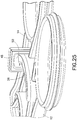
- Figures 1-35 show a speculum, and various features thereof.
- a speculum 10 is useable for opening, and maintaining in an open position, eyelids during ocular procedures or surgery.
- the speculum 10 is unitarily formed as one piece.
- the speculum 10 be formed from a thermoplastic material which is sterilizable.
- the speculum 10 is intended to be a single-use product which is sterilized, packaged for use, and discarded after use.
- the speculum 10 includes first and second arms 12, 14 which are connected by a hinge 16.
- the hinge 16 is unitarily formed with the first and second arms 12, 14.
- the first and second arms 12, 14 each include a distal end 18 having formed thereon a channel 20 adapted to the shape of an eyelid.
- the first and second arms 12, 14 each include a proximal end 22, located opposite the distal end 18.
- the hinge 16 is located at a mid-point of the first and second arms 12, 14 between the distal and proximal ends 18, 22.
- first and second arms 12, 14 may be rotated about an axis of rotation, designated by reference numeral 24, to selectively cause the distal ends 18 to come closer or further apart as need be.
- the speculum 10 be provided in the state shown in Figure 2 , with the distal ends 18, including the channels 20, being in proximity. This state corresponds to a pre-use state.
- the eyelids of a patient should be engaged with the speculum 10 being in the pre-use state. With subsequent separation of the distal ends 18, as represented by Figures 6 and 7 , a patient's eyelids may be engaged and caused to be opened to an open state, as represented by Figure 7 .
- first and second elements 26, 28 are unitarily formed on the first and second arms 12, 14, respectively.
- the first element 26 preferably includes a series of teeth 30, each defining a peak 32.
- the teeth 30 may be saw-tooth shaped, but other shapes are possible.
- Recesses 34 are defined between adjacent pairs of the teeth 30.
- the second element 28 preferably includes a pointer 36 formed to nest within the recesses 34 between the peaks 32 of adjacent pairs of the teeth 30. Two or more of the pointers 36 may be also arranged in series to engage the teeth 30, as shown in Figures 14-16 .
- the first and second elements 26, 28 may be reversibly located on the front and second arms 12, 14.
- the teeth 30 are configured to by-pass the pointer 36 over a predetermined range of relative movement between the first and second arms 12, 14.
- the pointer 36 is formed to restrict movement of the teeth 30 relative thereto.
- a pair of the set of teeth 30 is provided with a channel 38 therebetween.
- the channel 38 permits the teeth 30, particularly the two sets of the teeth 30, to straddle a portion of the second arm 14, in providing stability during interengagement of the corresponding elements.
- a pair of the pointers 36 may be utilized.
- the first and second elements 26, 28 are preferably separated and out of contact.
- the speculum 10 is maintained in the pre-use state, as shown in Figure 2 , through inherent memory provided to the speculum 10 during manufacturing.
- the first element 26 is caused to engage the second element 28, particularly with the teeth 30 by-passing the pointer 36.
- the pointer 36 imparts resistance against further separation of the distal ends 18 due to interfering interengagement with the teeth 30. A threshold amount of force allows such resistance to be overcome to permit adjustment of the teeth 30 relative to the pointer 26.
- the speculum 10 is used to open the eyelids of a patient and to maintain that open state.
- the degree to which the eyelids are opened may be adjusted as described above. It is noted that the eyelids may impart a reactionary closing force against the speculum 10.
- the threshold level of resistance against relative movement generated by the first and second elements 26, 28 must be greater than the closing force applied by the eyelids.
- the speculum 10 may be formed with additional features, such as with the first and second arms 12, 14 being curved, as shown in Figures 3-5 .
- the portions of the first and second arms 12, 14 between the hinge 16 and the distal ends 18 are curved away from a plane which intersects the proximal ends 22 and the hinge 16.
- the curved configuration permits placement of the speculum 10 during use adjacent to the eye and without interference of the curvature of a person's face.
- finger holes 40 may be formed at the proximal ends 22 to provide easier manipulation of the first and second arms 12, 14 for use.
- the hinge 16 is preferably a living hinge and may be formed with various configurations. With reference to Figures 1-7 , the hinge 16 may be formed as a strip of relatively uniform thickness. With reference to Figures 10-13 , the hinge 16 is preferably formed with thinned section 42 which permits easier rotation thereabout. The thinned section 42 provides greater predictability in operation of the hinge 16. More than one of the thinned sections 42 may be utilized. In addition, one or more ribs 44 may be provided about one or more of the thinned sections 42 so as to add additional rigidity to the hinge 16.
- the speculum 10 can be also provided with hard stops limiting the extent of relative movement between the first and second arms 12, 14.
- one or more stop blocks 41 may be provided to limit the movement of the first and second arms 12, 14, particularly to prevent the distal ends 18 from contacting.
- the stop blocks 41 may be located distally of the hinge 16 and shaped to come into interfering engagement with a predetermined extent of movement of the distal ends 18 coming together.
- the stop blocks 41 may extend from the first arm 12, the second arm 14 and/or the hinge 16.
- the stop blocks 41 may be wedge-shaped to come into contact over a limited region 43.
- portions of the distal end 18, for example at the channels 20, may come together to limit the extent of movement of the distal ends 18 coming together.
- the proximal ends 22 of the first and second arms 12, 14, may be configured to come into contact to limit the extent to which the distal ends 18 may be separated.
- the hinge 16 may be located at the proximal ends 22 of the first and second arms 12, 14 (opposite ends of the first and second arms 12, 14 from the channels 20 thereof). With this arrangement, the finger holes 40 may be located at midpoints on the first and second arms 12, 14 between the distal and proximal ends 18, 22. With the hinge 16 being located at the proximal ends 22, the distal ends 18 are caused to move apart by separating the first and second arms 12, 14 and, conversely, brought closer together by bringing the first and second arms 12, 14 together. As shown in Figures 14-16 , a side support 46 may be provided extending from the hinge 16. The side support 46 defines a resting surface for a third finger of a user during operation.
- a user may place a thumb and a forefinger in the finger holes 40 with a ring finger or pinkie being pressed against the side support 46 for additional stability.
- the side support 46 need not be provided.
- the finger holes 40 may be defined by a partial loop, as opposed to the complete loop shown, for example, in Figures 1-7 . It is preferred that the finger holes 40 have sufficient definition to accept and transmit force for both opening and closing the speculum 10.
- first and second elements 26, 28 in the embodiments discussed above are orientated to have the teeth 30 and the pointer 36 extend in a direction generally parallel to the longitudinal axes of the first and second arms 12, 14.
- the teeth 30 and the pointer 36 may be oriented in a direction generally perpendicular to the longitudinal axes of the first and second arms 12, 14.
- the first and second arms 12, 14 may be positionally adjusted by applying a torsional force about the hinge 16 to separate the first and second elements 26, 28. Once separated, the first and second arms 12, 14 are free to be positionally adjusted.
- an exemplary arch-shaped bridge 48 may be provided to limit the extent of separation of the first and second elements 26, 28.
- the bridge 48 may be formed on the second arm 14 with an opening 50 sized to permit passage therethrough of the first element 26.
- the opening 50 is sized to permit sufficient separation of the first and second elements 26, 28 to permit positional adjustment of the first and second arms 12, 14, yet limits excessive separation.
- the first and second elements 26, 28 may be separated axially by displacing one or both of the first and second arms 12, 14. In a separated state, the first and second arms 12, 14 may be positionally adjusted. It is preferred that the hinge 16 be located at the proximal ends 22 of the first and second arms 12, 14 for this arrangement.
- one or more features for retaining sutures may be provided.
- one or more suture cleats 52 may be located on the first arm 12 and/or the second arm 14, preferably in proximity to the distal end(s) 18.
- the suture cleats 52 each include a notch 54 formed to resiliently grip a thread or suture 56 therein.
- a sufficiently strong resilient grip is generated by each of the cleats 52 in the notch 54 to retain the suture 56 therein without movement of the suture 56 relative to the first and second arms 12, 14 during movement of the first and second arms 12, 14.
- the resilient grip is generated by the inherent resilience of portions of the cleats 52 surrounding the notch 54.
- one or more suture posts 58 may be provided about which sutures can be wrapped and tied off.
- an enlarged head 60 may be provided on each of the suture posts 58 which limits slippage of a suture from the suture post 58.
- the suture posts 58 may be easier to manufacture with the speculum 10 than the suture cleats 52, e.g., by injection molding.
- the speculum 10 is formed as a single, unitary piece.
- the speculum 10 is formed of a moldable thermoplastic material, which is sterilizeable. In this manner, the speculum 10 can be molded as a single piece in various molding techniques, such as injection molding. It is also preferred that the material of the speculum 10 not be capable of withstanding autoclaving. By not being capable of withstanding autoclaving, the likelihood of re-using the speculum 10 is greatly reduced. This minimizes potentially unsafe re-use.
- the speculum 10 be prepared with gamma radiation or gas (e.g., EtO) sterilization.
- gamma radiation or gas e.g., EtO
- the speculum 10 is provided as a one-piece article, which requires beyond initial molding no additional manufacturing or assembly steps, and which is single-use, which limits improper and potentially unsafe re-use.
Description
- This invention relates to speculums for opening, and maintaining in an open position, eyelids, and, more particular, to speculums having arrangements for being retained at specific open positions.
- Speculums are know in the prior art for opening, and maintaining in an open position, eyelids during ocular procedures or surgery. Prior art speculums include bent-wire speculums where the speculum is formed from a unitary piece of resilient wire. The speculums are provided in unbiased, rest states, corresponding to the open position of the eyelids. For use, the speculums are compressed to engage the eyelids and, then, allowed to expand to cause opening thereof. These speculums have no provision for positional adjustment or being retained at a particular position. The inherently generated elastic force is used to maintain these speculums during use.
- Speculums have been also provided in the prior art with separate positional adjustment arrangements. For example, speculums have been provided which include a bolt spanning between the arms of the speculum, wherein threaded movement of a nut along the length of the bolt causes positional adjustment of one or both of the arms. These speculums require components in addition to the speculum itself.
- Documents
WO 92/18055 A1 RU 2 020 860 C1 FR 712.704 A - In one aspect, a speculum according to claim 1 or 13 is provided.The speculum includes a first arm having a first channel formed thereon adapted to the shape of an eyelid; a second arm having a second channel formed thereon adapted to the shape of an eyelid; a hinge unitarily formed with the first and second arms, the hinge permitting the first and second arms to selectively rotate about an axis rotation, the selective rotation causing the first and second channels to selectively move closer and farther apart; and, a position retaining arrangement. The position retaining arrangement includes a first element formed unitarily with the first arm, and a second element formed unitarily with the second arm. The first and second elements are configured to cooperatively retain the first and second arms in a selected rotational position. Advantageously, with the subject invention, a unitary speculum may be formed which includes an adjustable position retaining arrangement.
- These and other features of the invention will be better understood through a study of the following detailed description and accompanying drawings.
-
Figures 1-35 show a speculum, and various features thereof. - With reference to the Figures, various embodiments of a
speculum 10 are shown. Thespeculum 10 is useable for opening, and maintaining in an open position, eyelids during ocular procedures or surgery. Preferably, thespeculum 10 is unitarily formed as one piece. In addition, it is preferred that thespeculum 10 be formed from a thermoplastic material which is sterilizable. Thespeculum 10 is intended to be a single-use product which is sterilized, packaged for use, and discarded after use. - With reference to
Figures 1-9 , a preferred embodiment of thespeculum 10 is shown. In particular, thespeculum 10 includes first andsecond arms hinge 16. Preferably, thehinge 16 is unitarily formed with the first andsecond arms second arms distal end 18 having formed thereon achannel 20 adapted to the shape of an eyelid. The first andsecond arms proximal end 22, located opposite thedistal end 18. In the preferred embodiment, as shown inFigures 1-7 , thehinge 16 is located at a mid-point of the first andsecond arms proximal ends - With reference to
Figures 2 ,6 and 7 , movement of theproximal ends 22 of the first andsecond arms distal ends 18, including thechannels 20, of the first andsecond arms proximal ends 22 results in thedistal ends 18, including thechannels 20, coming closer together. In this manner, the first andsecond arms reference numeral 24, to selectively cause thedistal ends 18 to come closer or further apart as need be. It is preferred that in an initial state, thespeculum 10 be provided in the state shown inFigure 2 , with thedistal ends 18, including thechannels 20, being in proximity. This state corresponds to a pre-use state. The eyelids of a patient should be engaged with thespeculum 10 being in the pre-use state. With subsequent separation of thedistal ends 18, as represented byFigures 6 and 7 , a patient's eyelids may be engaged and caused to be opened to an open state, as represented byFigure 7 . - It is preferred that the
speculum 10 be provided with a position retaining arrangement, whereby the first andsecond arms Figures 8 and 9 , complementary first andsecond elements second arms first element 26 preferably includes a series ofteeth 30, each defining apeak 32. By way of nonlimiting example, theteeth 30 may be saw-tooth shaped, but other shapes are possible.Recesses 34 are defined between adjacent pairs of theteeth 30. Thesecond element 28 preferably includes apointer 36 formed to nest within therecesses 34 between thepeaks 32 of adjacent pairs of theteeth 30. Two or more of thepointers 36 may be also arranged in series to engage theteeth 30, as shown inFigures 14-16 . As will be appreciated by those skilled in the art, the first andsecond elements second arms - Preferably, the
teeth 30 are configured to by-pass thepointer 36 over a predetermined range of relative movement between the first andsecond arms pointer 36 is formed to restrict movement of theteeth 30 relative thereto. - As shown in
Figure 8 , in a preferred embodiment, a pair of the set ofteeth 30 is provided with achannel 38 therebetween. Thechannel 38 permits theteeth 30, particularly the two sets of theteeth 30, to straddle a portion of thesecond arm 14, in providing stability during interengagement of the corresponding elements. In addition, a pair of thepointers 36 may be utilized. - With reference to
Figures 1 and2 , in the initial pre-use state, the first andsecond elements speculum 10 is maintained in the pre-use state, as shown inFigure 2 , through inherent memory provided to thespeculum 10 during manufacturing. - During use, and with initial coming together of the
proximal ends 22 of the first andsecond arms distal ends 18, thefirst element 26 is caused to engage thesecond element 28, particularly with theteeth 30 by-passing thepointer 36. Thepointer 36 imparts resistance against further separation of thedistal ends 18 due to interfering interengagement with theteeth 30. A threshold amount of force allows such resistance to be overcome to permit adjustment of theteeth 30 relative to thepointer 26. - With the
pointer 36 nesting between adjacent pairs of theteeth 30, the relative positions of the first andsecond arms Figures 6 and 7 , adjusted from the pre-use state ofFigure 2 , may be achieved and maintained. - The
speculum 10 is used to open the eyelids of a patient and to maintain that open state. The degree to which the eyelids are opened may be adjusted as described above. It is noted that the eyelids may impart a reactionary closing force against thespeculum 10. The threshold level of resistance against relative movement generated by the first andsecond elements - With a procedure being completed, force is applied to separate the
proximal ends 22 of the first andsecond arms teeth 30 past thepointer 36 to return thespeculum 10 to a state permitting thechannels 22 to be removed from a patient's eyelids. Thespeculum 10 is intended for single use. - The
speculum 10 may be formed with additional features, such as with the first andsecond arms Figures 3-5 . Preferably, the portions of the first andsecond arms hinge 16 and the distal ends 18 are curved away from a plane which intersects the proximal ends 22 and thehinge 16. The curved configuration permits placement of thespeculum 10 during use adjacent to the eye and without interference of the curvature of a person's face. In addition, finger holes 40 may be formed at the proximal ends 22 to provide easier manipulation of the first andsecond arms - As will be appreciated by those skilled in the art, the
hinge 16 is preferably a living hinge and may be formed with various configurations. With reference toFigures 1-7 , thehinge 16 may be formed as a strip of relatively uniform thickness. With reference toFigures 10-13 , thehinge 16 is preferably formed with thinnedsection 42 which permits easier rotation thereabout. The thinnedsection 42 provides greater predictability in operation of thehinge 16. More than one of the thinnedsections 42 may be utilized. In addition, one ormore ribs 44 may be provided about one or more of the thinnedsections 42 so as to add additional rigidity to thehinge 16. - The
speculum 10 can be also provided with hard stops limiting the extent of relative movement between the first andsecond arms Figures 26-29 , one or more stop blocks 41 may be provided to limit the movement of the first andsecond arms Figure 2 , the stop blocks 41 may be located distally of thehinge 16 and shaped to come into interfering engagement with a predetermined extent of movement of the distal ends 18 coming together. The stop blocks 41 may extend from thefirst arm 12, thesecond arm 14 and/or thehinge 16. The stop blocks 41 may be wedge-shaped to come into contact over alimited region 43. Due to the interfering engagement, contact between the distal ends 18 may be avoided and, as such, interference therebetween may be avoided. With reference toFigure 2 , portions of thedistal end 18, for example at thechannels 20, may come together to limit the extent of movement of the distal ends 18 coming together. In addition, with reference toFigure 7 , the proximal ends 22 of the first andsecond arms - With reference to
Figures 14-18 , thehinge 16 may be located at the proximal ends 22 of the first andsecond arms 12, 14 (opposite ends of the first andsecond arms channels 20 thereof). With this arrangement, the finger holes 40 may be located at midpoints on the first andsecond arms hinge 16 being located at the proximal ends 22, the distal ends 18 are caused to move apart by separating the first andsecond arms second arms Figures 14-16 , aside support 46 may be provided extending from thehinge 16. Theside support 46 defines a resting surface for a third finger of a user during operation. Thus, with the configuration ofFigures 14-16 , a user may place a thumb and a forefinger in the finger holes 40 with a ring finger or pinkie being pressed against theside support 46 for additional stability. As shown inFigure 17 , theside support 46 need not be provided. - With respect to
Figure 18 , it is noted that the finger holes 40 may be defined by a partial loop, as opposed to the complete loop shown, for example, inFigures 1-7 . It is preferred that the finger holes 40 have sufficient definition to accept and transmit force for both opening and closing thespeculum 10. - It is also noted that the first and
second elements teeth 30 and thepointer 36 extend in a direction generally parallel to the longitudinal axes of the first andsecond arms Figures 19-23 , theteeth 30 and thepointer 36 may be oriented in a direction generally perpendicular to the longitudinal axes of the first andsecond arms Figures 22 and23 , the first andsecond arms hinge 16 to separate the first andsecond elements second arms second elements speculum 10 causes the first andsecond arms second elements Figures 24-25 , an exemplary arch-shapedbridge 48 may be provided to limit the extent of separation of the first andsecond elements Figures 24-25 , thebridge 48 may be formed on thesecond arm 14 with anopening 50 sized to permit passage therethrough of thefirst element 26. Theopening 50 is sized to permit sufficient separation of the first andsecond elements second arms - Alternatively, as shown in
Figure 17A , the first andsecond elements second arms second arms hinge 16 be located at the proximal ends 22 of the first andsecond arms - As a further variation, and with reference to
Figures 26-35 , one or more features for retaining sutures may be provided. For example, with reference toFigures 26-32 , one ormore suture cleats 52 may be located on thefirst arm 12 and/or thesecond arm 14, preferably in proximity to the distal end(s) 18. The suture cleats 52 each include anotch 54 formed to resiliently grip a thread orsuture 56 therein. Preferably, a sufficiently strong resilient grip is generated by each of thecleats 52 in thenotch 54 to retain thesuture 56 therein without movement of thesuture 56 relative to the first andsecond arms second arms cleats 52 surrounding thenotch 54. Preferably, and with reference toFigures 33-35 , one ormore suture posts 58 may be provided about which sutures can be wrapped and tied off. To minimize inadvertent slippage, anenlarged head 60 may be provided on each of the suture posts 58 which limits slippage of a suture from thesuture post 58. The suture posts 58 may be easier to manufacture with thespeculum 10 than thesuture cleats 52, e.g., by injection molding. - As will be appreciated by those skilled in the art, the various features discussed herein may be used in various combinations with the
speculum 10. Thespeculum 10 is formed as a single, unitary piece. Preferably, thespeculum 10 is formed of a moldable thermoplastic material, which is sterilizeable. In this manner, thespeculum 10 can be molded as a single piece in various molding techniques, such as injection molding. It is also preferred that the material of thespeculum 10 not be capable of withstanding autoclaving. By not being capable of withstanding autoclaving, the likelihood of re-using thespeculum 10 is greatly reduced. This minimizes potentially unsafe re-use. In initial manufacturing, it is preferred that thespeculum 10 be prepared with gamma radiation or gas (e.g., EtO) sterilization. Advantageously, thespeculum 10 is provided as a one-piece article, which requires beyond initial molding no additional manufacturing or assembly steps, and which is single-use, which limits improper and potentially unsafe re-use.
Claims (13)
- A speculum comprising:a first arm (12) having a first channel (20) formed thereon adapted to the shape of an eyelid;a second arm (14) having a second channel (20) formed thereon adapted to the shape of an eyelid, said second channel (20) facing away from said first channel (20);a living hinge (16) unitarily formed with said first and second arms (12, 14), said hinge (16) permitting said first and second arms (12, 14) to selectively rotate about an axis of rotation (24), said selective rotation causing said first and second channels (20) to selectively move closer and farther apart; and,a position retaining arrangement including:two first elements (26) formed unitarily with said first arm (12), said first elements (26) being spaced in a direction parallel to said axis of rotation so as to define a channel (38) therebetween; and,a second element (28) formed unitarily with said second arm (14);wherein, said two first elements (26) and second element (28) being configured to cooperatively retain said first and second arms (12, 14) in a selected rotational position,wherein, the speculum is unitarily formed by molding as one piece,wherein with said two first elements (26) and second element (28) being in cooperative retention, said two first elements (26) straddle said second arm (14) with a portion of said second arm (14) received in said channel (38).
- A speculum as in claim 1, wherein said two first elements (26) and second element (28) are configured to interferingly interengage so as to limit rotational movement of said first and second arms (12, 14).
- A speculum as in claim 2, wherein said two first elements (26) and second element (28) are separable to permit rotation of said first and second arms (12, 14).
- A speculum as in claim 2, wherein a predetermined amount of force may be applied to cause selective rotation of said first and second arms (12, 14), said predetermined amount of force being sufficient to overcome the retaining force generated by said two first elements (26) and second element (28).
- A speculum as in claim 1, wherein said first arm (12) includes a finger hole (40).
- A speculum as in claim 1, wherein the speculum is formed of thermoplastic.
- A speculum as in claim 1, wherein said hinge (16) is located along a mid-point of said first and second arms (12, 14).
- A speculum as in claim 1, wherein, in an initial state, said first and second channels (20) are in proximity.
- A speculum as in claim 1, wherein, in an initial state, said first and second elements (26, 28) are separated and out of contact.
- A speculum as in claim 1, further comprising stop blocks (41) configured to limit the extent of rotation of said first and second arms (12, 14).
- A speculum as in claim 1, wherein said hinge (16) is located on said first and second arms (12, 14) at opposite ends from said channels (20) thereof.
- A speculum as in claim 1, further comprising one or more features (52, 54) for retaining sutures (56).
- A speculum comprising:a first arm (12) having a first channel (20) formed thereon adapted to the shape of an eyelid;a second arm (14) having a second channel (20) formed thereon adapted to the shape of an eyelid, said second channel (20) facing away from said first channel (20);a living hinge (16) connecting said first and second arms (12, 14), said hinge (16) permitting said first and second arms (12, 14) to selectively rotate about an axis of rotation (26), said selective rotation causing said first and second channels (20) to selectively move closer and farther apart;two first elements (26) on said first arm (12), said two first elements (26) being spaced apart in a direction parallel to said axis of rotation (26) so as to define a channel (38) therebetween; and,a second element (28) on said second arm (14);wherein, said two first elements (26) and second element (28) are configured to cooperatively retain said first and second arms (12, 14) in a rotational positions with interfering interengagement between said first and second elements (26, 28) limiting rotation of said first and second arms,wherein, the speculum is unitarily formed by molding as one piece,wherein with said two first elements (26) and second element (28) being in cooperative retention, said two first elements (26) straddle said second arm (14) with a portion of said second arm (14) received in said channel (38).
Applications Claiming Priority (3)
| Application Number | Priority Date | Filing Date | Title |
|---|---|---|---|
| US25426309P | 2009-10-23 | 2009-10-23 | |
| US30376410P | 2010-02-12 | 2010-02-12 | |
| PCT/US2010/053909 WO2011050352A1 (en) | 2009-10-23 | 2010-10-25 | Speculum |
Publications (2)
| Publication Number | Publication Date |
|---|---|
| EP2490597A1 EP2490597A1 (en) | 2012-08-29 |
| EP2490597B1 true EP2490597B1 (en) | 2019-08-14 |
Family
ID=43086047
Family Applications (1)
| Application Number | Title | Priority Date | Filing Date |
|---|---|---|---|
| EP10770934.7A Active EP2490597B1 (en) | 2009-10-23 | 2010-10-25 | Speculum |
Country Status (7)
| Country | Link |
|---|---|
| US (2) | US8652036B2 (en) |
| EP (1) | EP2490597B1 (en) |
| JP (1) | JP2013514817A (en) |
| CN (1) | CN102647947A (en) |
| BR (1) | BR112012010836A2 (en) |
| RU (1) | RU2554225C2 (en) |
| WO (1) | WO2011050352A1 (en) |
Families Citing this family (14)
| Publication number | Priority date | Publication date | Assignee | Title |
|---|---|---|---|---|
| US9610072B2 (en) | 2009-11-02 | 2017-04-04 | Apx Opthalmology Ltd. | Iris retractor |
| DE102010054333B4 (en) * | 2010-12-13 | 2019-05-29 | Stryker European Holdings I, LLC (n.d. Ges. d. Staates Delaware) | Surgical retractor |
| US9095322B2 (en) | 2011-09-21 | 2015-08-04 | Beaver-Visitec International (Us), Inc. | Speculum with hinged portion |
| US20160074054A1 (en) * | 2013-04-19 | 2016-03-17 | Apx Ophthalmology Ltd. | Iris retractor forceps |
| CN103536321A (en) * | 2013-11-12 | 2014-01-29 | 冉旭东 | Full-angle three-dimensional adjustable retractor |
| US9289199B1 (en) * | 2014-01-09 | 2016-03-22 | Neotech Products, Inc. | Retinal examination apparatus |
| US20210228072A1 (en) * | 2016-03-04 | 2021-07-29 | Mayo Foundation For Medical Education And Research | Transoral surgical devices and methods |
| US10994396B2 (en) * | 2016-09-13 | 2021-05-04 | B&B Solutions, LLC | Apparatus and method for assisted buckle release |
| DE102017102027A1 (en) | 2017-02-02 | 2018-08-02 | Aesculap Ag | Surgical instrument with lockable thighs |
| USD828552S1 (en) * | 2017-02-24 | 2018-09-11 | Gregory A. Eippert | Lid speculum |
| IT201800005894A1 (en) * | 2018-05-31 | 2019-12-01 | MULTIFUNCTIONAL GRIPPER | |
| CN109646064A (en) * | 2018-12-21 | 2019-04-19 | 董宁宁 | A kind of adjustable eyelid stretching apparatus for clinical ophthalmology |
| JP2020124330A (en) * | 2019-02-04 | 2020-08-20 | 裕貴 田邊 | Eyelid opening tool |
| CN111803151A (en) * | 2020-07-03 | 2020-10-23 | 台州市黄岩喃语电子商务有限公司 | Eyelid retractor with adjustable opening degree |
Citations (1)
| Publication number | Priority date | Publication date | Assignee | Title |
|---|---|---|---|---|
| US4365625A (en) * | 1980-09-17 | 1982-12-28 | Bruce Rind | Expandable oral airway |
Family Cites Families (70)
| Publication number | Priority date | Publication date | Assignee | Title |
|---|---|---|---|---|
| US595512A (en) * | 1897-12-14 | Wrench | ||
| US835968A (en) * | 1906-02-28 | 1906-11-13 | Wilhelm Johannes Mennes | Apparatus for stretching fingers. |
| US1067572A (en) * | 1912-03-21 | 1913-07-15 | James Herman Abbott | Mouth-prop. |
| US1472380A (en) * | 1921-01-24 | 1923-10-30 | American Protein Corp | Clamp |
| FR712704A (en) | 1931-03-04 | 1931-10-09 | Blepharostat with levers | |
| US2075534A (en) * | 1933-10-13 | 1937-03-30 | Charles V Mccormack | Mouth prop |
| US2291413A (en) * | 1941-06-13 | 1942-07-28 | John R Siebrandt | Bone clamping and wire adjusting means |
| US2583892A (en) * | 1950-12-26 | 1952-01-29 | Shellhouse Michael | Hysterectomy forceps |
| US2702540A (en) * | 1953-07-07 | 1955-02-22 | Ali Y Debeh | Eyelid retracting device |
| US3038467A (en) * | 1960-08-29 | 1962-06-12 | Sklar Mfg Co J | Surgical instrument |
| US3316913A (en) * | 1964-02-28 | 1967-05-02 | Rudolph E Swenson | Catheter guiding forceps |
| US3367336A (en) * | 1965-07-26 | 1968-02-06 | Pharmaseal Lab | Disposable medical forceps |
| US3392727A (en) * | 1965-09-15 | 1968-07-16 | Johnson & Johnson | Thumb forceps |
| US3470872A (en) * | 1966-11-25 | 1969-10-07 | Herman R Grieshaber | Pivoted retractor with shielded spacer teeth |
| GB1253526A (en) * | 1968-11-29 | 1971-11-17 | Ici Ltd | Compound lever mechanism |
| US3809094A (en) * | 1969-12-24 | 1974-05-07 | G Cook | Tongue extender |
| US3616497A (en) * | 1970-06-24 | 1971-11-02 | Vincent J Esposito Jr | Integral clamping instruments for medical and surgical applications |
| US3972333A (en) * | 1973-03-02 | 1976-08-03 | Leveen Harry H | Disposable surgical tool |
| GB1427397A (en) * | 1973-04-24 | 1976-03-10 | Ici Ltd | Forceps |
| SE7316352L (en) * | 1973-12-04 | 1975-05-05 | ||
| US4257406A (en) * | 1979-05-18 | 1981-03-24 | Schenk Alan G | Iris retractor and pupil dilator |
| US4386608A (en) * | 1981-07-15 | 1983-06-07 | Ehrlich Kenneth B | Eye irrigating apparatus |
| IT1194556B (en) * | 1983-03-11 | 1988-09-22 | Carlo Rebuffat | CURVED BRANCH ENTER SWITCH FOR THE AUTOMATIC EXECUTION OF TOBACCO BAG SUTURES ON CABLE VISCERS |
| US4526172A (en) * | 1983-08-25 | 1985-07-02 | Premium Plastics, Inc. | One piece multi-purpose clamp |
| US5054906A (en) * | 1986-01-17 | 1991-10-08 | Brimfield Precision, Inc. | Indirectly illuminating ophthalmological speculum |
| SU1405824A1 (en) * | 1986-07-30 | 1988-06-30 | Сибирский физико-технический институт им.В.Д.Кузнецова при Томском государственном университете | Nasodilator |
| US4754746A (en) * | 1986-09-25 | 1988-07-05 | Cox Kenneth L | Self-retaining metatarsal spreader |
| CH673938A5 (en) * | 1987-12-04 | 1990-04-30 | Grounauer Pierre Alain | |
| US5341798A (en) * | 1987-12-04 | 1994-08-30 | Grounauer Pierre Alain | Retractor device for human or animal tissue |
| USD314826S (en) * | 1989-04-27 | 1991-02-19 | Torre Randall J | Short bone retractor |
| US5002561A (en) * | 1989-08-17 | 1991-03-26 | Fisher Frank E | Protective hand forceps |
| SU1736487A1 (en) | 1990-07-06 | 1992-05-30 | Межотраслевой научно-технический комплекс "Микрохирургия глаза" | Blepharostat |
| RU2020860C1 (en) | 1991-04-11 | 1994-10-15 | Линник Леонид Феодосьевич | Blepharostat |
| SU1824723A1 (en) | 1991-04-11 | 1996-10-27 | Межотраслевой научно-технический комплекс "Микрохирургия глаза" | Eye lid expander |
| CN2127301Y (en) * | 1992-06-10 | 1993-02-24 | 张雁军 | Pliers-type surgical drag hook |
| US5464413A (en) * | 1993-11-15 | 1995-11-07 | Siska, Jr.; William | Nose clip |
| US5441040A (en) * | 1994-02-02 | 1995-08-15 | Williams, Jr.; Barney K. | RDS speculum |
| US5462435A (en) * | 1994-02-22 | 1995-10-31 | Young; James P. | Adjustable mouth prop |
| US5522290A (en) * | 1994-04-18 | 1996-06-04 | Visser; Steven C. | Compliant pliers |
| US5484447A (en) * | 1994-07-26 | 1996-01-16 | Duckworth & Kent Limited | Calipers for use in ophthalmic surgery |
| US5514148A (en) * | 1994-11-04 | 1996-05-07 | Smith, Iii; Ray C. | Surgical clamp and method of use |
| US5556403A (en) * | 1995-02-08 | 1996-09-17 | Michalos; Peter | Surgical needle holder for securing a needle at a selected position |
| US5591203A (en) * | 1995-03-24 | 1997-01-07 | Organ, Inc. | Anastomosis cuff manipulator tool |
| US5697933A (en) * | 1995-12-18 | 1997-12-16 | Medicinelodge, Inc. | Bone-tendon-bone drill guide |
| US5746757A (en) * | 1996-01-17 | 1998-05-05 | Mcguire; David A. | Suturing jig and method for using same |
| US5797919A (en) * | 1996-07-16 | 1998-08-25 | Brinson; Keith Anthony | Surgical bone clamp |
| DE69816306T2 (en) * | 1997-02-13 | 2004-05-27 | Boston Scientific Ltd., St. Michael | DILATATOR FOR MINIMALLY INVASIVE PELVIC SURGERY |
| US5997566A (en) * | 1998-07-14 | 1999-12-07 | Tobin; Joshua | Cricothyrotomy forceps |
| US7189234B2 (en) * | 1998-10-20 | 2007-03-13 | St. Francis Medical Technologies, Inc. | Interspinous process implant sizer and distractor with a split head and size indicator and method |
| US6159217A (en) * | 1999-02-02 | 2000-12-12 | Robie; Bruce H. | Trochlear clamp |
| CN2388920Y (en) * | 1999-03-22 | 2000-07-26 | 郑国强 | Multi-function apparatus for cardiac valve replacement operation |
| US6283913B1 (en) * | 1999-04-09 | 2001-09-04 | Barry S. Seibel | 3-dimensional lid speculum and method for use |
| CN2430949Y (en) * | 2000-07-14 | 2001-05-23 | 白俊清 | Automatic tooth plate type retractor |
| US6635072B1 (en) * | 2000-07-20 | 2003-10-21 | Synthes | Safety ratchet mechanism |
| USD448080S1 (en) * | 2001-01-11 | 2001-09-18 | Innovative Surgical Design, Llc | Episiotomy retractor |
| US6302842B1 (en) | 2001-01-11 | 2001-10-16 | Innovative Surgical Design Llc | Episiotomy retractor |
| US6544169B2 (en) * | 2001-01-29 | 2003-04-08 | Barzell Whitmore Maroon Bells, Inc. | Eyelid retraction device |
| US6440065B1 (en) * | 2001-10-01 | 2002-08-27 | The Nemours Foundation | Single-use disposable eyelid speculum, eye examination kit, and method for examining a patient's eye |
| JP2005027933A (en) * | 2003-07-08 | 2005-02-03 | Silver Medical:Kk | Surgical retractor |
| JP2005028001A (en) * | 2003-07-10 | 2005-02-03 | Showa Ika Kohgyo Co Ltd | Retractor |
| US8647348B2 (en) * | 2006-04-17 | 2014-02-11 | Kwok Wai Chiu | Apparatus for adult circumcision |
| DE102006021889A1 (en) | 2006-05-11 | 2007-11-15 | Thederan, Heinz, Dr. med. Dipl.-Ing. (FH) | Eyelid fixing tweezer e.g. lower eyelid blepharochalasis tweezer, has lower clamping jaw comprising body, which is arranged in form of bent plate, where body is bent with radius of curvature corresponding to curvature of lower eyelid |
| US20080172085A1 (en) * | 2007-01-16 | 2008-07-17 | Kwok Wai Chiu | Elliptical Excision Clamp |
| US20080177297A1 (en) * | 2007-01-24 | 2008-07-24 | Musculoskeletal Transplant Foundation | Forceps |
| US20080234765A1 (en) * | 2007-03-13 | 2008-09-25 | Depuy Spine, Inc. | Rod reduction methods and devices |
| US8066635B2 (en) * | 2008-03-05 | 2011-11-29 | Thb Precision, Llc | Speculum |
| CN201299604Y (en) * | 2008-11-26 | 2009-09-02 | 同济大学 | Sternal distraction device |
| US20100331878A1 (en) * | 2009-06-25 | 2010-12-30 | Carl Zeiss Surgical Gmbh | Method and device for removing a balloon from a body cavity |
| US8257256B1 (en) * | 2009-10-22 | 2012-09-04 | Krolman Arthur M M | Retractor device |
| USD663416S1 (en) * | 2011-09-21 | 2012-07-10 | Beaver-Visitec International (Us), Inc. | Speculum with slotted arm |
-
2010
- 2010-10-25 JP JP2012535440A patent/JP2013514817A/en active Pending
- 2010-10-25 CN CN2010800545107A patent/CN102647947A/en active Pending
- 2010-10-25 US US12/911,110 patent/US8652036B2/en active Active
- 2010-10-25 RU RU2012121179/14A patent/RU2554225C2/en active
- 2010-10-25 WO PCT/US2010/053909 patent/WO2011050352A1/en active Application Filing
- 2010-10-25 EP EP10770934.7A patent/EP2490597B1/en active Active
- 2010-10-25 BR BR112012010836A patent/BR112012010836A2/en not_active Application Discontinuation
-
2014
- 2014-02-04 US US14/172,128 patent/US20140155700A1/en not_active Abandoned
Patent Citations (1)
| Publication number | Priority date | Publication date | Assignee | Title |
|---|---|---|---|---|
| US4365625A (en) * | 1980-09-17 | 1982-12-28 | Bruce Rind | Expandable oral airway |
Also Published As
| Publication number | Publication date |
|---|---|
| RU2554225C2 (en) | 2015-06-27 |
| US8652036B2 (en) | 2014-02-18 |
| US20140155700A1 (en) | 2014-06-05 |
| WO2011050352A1 (en) | 2011-04-28 |
| CN102647947A (en) | 2012-08-22 |
| EP2490597A1 (en) | 2012-08-29 |
| BR112012010836A2 (en) | 2022-10-11 |
| US20110098538A1 (en) | 2011-04-28 |
| RU2012121179A (en) | 2013-11-27 |
| JP2013514817A (en) | 2013-05-02 |
Similar Documents
| Publication | Publication Date | Title |
|---|---|---|
| EP2490597B1 (en) | Speculum | |
| EP2895079B1 (en) | Disposable capsulorhexis forceps | |
| US7182775B2 (en) | Super atraumatic grasper apparatus | |
| US9095322B2 (en) | Speculum with hinged portion | |
| US20050125013A1 (en) | Safety surgical forceps | |
| US10105515B2 (en) | Control handle for catheters or cannulas for medical use | |
| WO2007080868A1 (en) | Instrument for inserting intraocular lens | |
| US20090187153A1 (en) | Winged needle assembly and frangible cover | |
| EP2444007A1 (en) | Stitch-removal pincer | |
| US20030233119A1 (en) | Port deaccessor and methods of use | |
| US6299617B1 (en) | Instrument for fixating the eye during cataract surgery | |
| US20140288380A1 (en) | Iris retractor assemblies | |
| EP2043523B1 (en) | Lancet | |
| CN203802655U (en) | Eyelash pulling tweezers | |
| JP5285398B2 (en) | Open device | |
| CN218105986U (en) | Miniature surgical clamp antiskid binding clip | |
| CN114343878B (en) | Eyelid opening device for ophthalmic nursing | |
| CN219516451U (en) | Disposable microstructure forceps device | |
| US11497649B2 (en) | Intracanalicular dissolvable punctum plug inserter | |
| JP5467665B2 (en) | Open device | |
| JP2018175573A (en) | Micro forceps | |
| WO2010095152A1 (en) | Safety device for disposable sanitary hollow needles and cutters |
Legal Events
| Date | Code | Title | Description |
|---|---|---|---|
| PUAI | Public reference made under article 153(3) epc to a published international application that has entered the european phase |
Free format text: ORIGINAL CODE: 0009012 |
|
| 17P | Request for examination filed |
Effective date: 20120509 |
|
| AK | Designated contracting states |
Kind code of ref document: A1 Designated state(s): AL AT BE BG CH CY CZ DE DK EE ES FI FR GB GR HR HU IE IS IT LI LT LU LV MC MK MT NL NO PL PT RO RS SE SI SK SM TR |
|
| DAX | Request for extension of the european patent (deleted) | ||
| RIN1 | Information on inventor provided before grant (corrected) |
Inventor name: TERRY, FREDERICK, M. Inventor name: COTE, DANA |
|
| STAA | Information on the status of an ep patent application or granted ep patent |
Free format text: STATUS: EXAMINATION IS IN PROGRESS |
|
| 17Q | First examination report despatched |
Effective date: 20161104 |
|
| GRAP | Despatch of communication of intention to grant a patent |
Free format text: ORIGINAL CODE: EPIDOSNIGR1 |
|
| STAA | Information on the status of an ep patent application or granted ep patent |
Free format text: STATUS: GRANT OF PATENT IS INTENDED |
|
| INTG | Intention to grant announced |
Effective date: 20190220 |
|
| GRAS | Grant fee paid |
Free format text: ORIGINAL CODE: EPIDOSNIGR3 |
|
| GRAA | (expected) grant |
Free format text: ORIGINAL CODE: 0009210 |
|
| STAA | Information on the status of an ep patent application or granted ep patent |
Free format text: STATUS: THE PATENT HAS BEEN GRANTED |
|
| AK | Designated contracting states |
Kind code of ref document: B1 Designated state(s): AL AT BE BG CH CY CZ DE DK EE ES FI FR GB GR HR HU IE IS IT LI LT LU LV MC MK MT NL NO PL PT RO RS SE SI SK SM TR |
|
| REG | Reference to a national code |
Ref country code: GB Ref legal event code: FG4D |
|
| REG | Reference to a national code |
Ref country code: CH Ref legal event code: EP Ref country code: AT Ref legal event code: REF Ref document number: 1166069 Country of ref document: AT Kind code of ref document: T Effective date: 20190815 |
|
| REG | Reference to a national code |
Ref country code: IE Ref legal event code: FG4D |
|
| REG | Reference to a national code |
Ref country code: DE Ref legal event code: R096 Ref document number: 602010060567 Country of ref document: DE |
|
| REG | Reference to a national code |
Ref country code: NL Ref legal event code: MP Effective date: 20190814 |
|
| REG | Reference to a national code |
Ref country code: LT Ref legal event code: MG4D |
|
| PG25 | Lapsed in a contracting state [announced via postgrant information from national office to epo] |
Ref country code: FI Free format text: LAPSE BECAUSE OF FAILURE TO SUBMIT A TRANSLATION OF THE DESCRIPTION OR TO PAY THE FEE WITHIN THE PRESCRIBED TIME-LIMIT Effective date: 20190814 Ref country code: LT Free format text: LAPSE BECAUSE OF FAILURE TO SUBMIT A TRANSLATION OF THE DESCRIPTION OR TO PAY THE FEE WITHIN THE PRESCRIBED TIME-LIMIT Effective date: 20190814 Ref country code: NL Free format text: LAPSE BECAUSE OF FAILURE TO SUBMIT A TRANSLATION OF THE DESCRIPTION OR TO PAY THE FEE WITHIN THE PRESCRIBED TIME-LIMIT Effective date: 20190814 Ref country code: BG Free format text: LAPSE BECAUSE OF FAILURE TO SUBMIT A TRANSLATION OF THE DESCRIPTION OR TO PAY THE FEE WITHIN THE PRESCRIBED TIME-LIMIT Effective date: 20191114 Ref country code: HR Free format text: LAPSE BECAUSE OF FAILURE TO SUBMIT A TRANSLATION OF THE DESCRIPTION OR TO PAY THE FEE WITHIN THE PRESCRIBED TIME-LIMIT Effective date: 20190814 Ref country code: PT Free format text: LAPSE BECAUSE OF FAILURE TO SUBMIT A TRANSLATION OF THE DESCRIPTION OR TO PAY THE FEE WITHIN THE PRESCRIBED TIME-LIMIT Effective date: 20191216 Ref country code: NO Free format text: LAPSE BECAUSE OF FAILURE TO SUBMIT A TRANSLATION OF THE DESCRIPTION OR TO PAY THE FEE WITHIN THE PRESCRIBED TIME-LIMIT Effective date: 20191114 Ref country code: SE Free format text: LAPSE BECAUSE OF FAILURE TO SUBMIT A TRANSLATION OF THE DESCRIPTION OR TO PAY THE FEE WITHIN THE PRESCRIBED TIME-LIMIT Effective date: 20190814 |
|
| REG | Reference to a national code |
Ref country code: AT Ref legal event code: MK05 Ref document number: 1166069 Country of ref document: AT Kind code of ref document: T Effective date: 20190814 |
|
| PG25 | Lapsed in a contracting state [announced via postgrant information from national office to epo] |
Ref country code: RS Free format text: LAPSE BECAUSE OF FAILURE TO SUBMIT A TRANSLATION OF THE DESCRIPTION OR TO PAY THE FEE WITHIN THE PRESCRIBED TIME-LIMIT Effective date: 20190814 Ref country code: IS Free format text: LAPSE BECAUSE OF FAILURE TO SUBMIT A TRANSLATION OF THE DESCRIPTION OR TO PAY THE FEE WITHIN THE PRESCRIBED TIME-LIMIT Effective date: 20191214 Ref country code: GR Free format text: LAPSE BECAUSE OF FAILURE TO SUBMIT A TRANSLATION OF THE DESCRIPTION OR TO PAY THE FEE WITHIN THE PRESCRIBED TIME-LIMIT Effective date: 20191115 Ref country code: LV Free format text: LAPSE BECAUSE OF FAILURE TO SUBMIT A TRANSLATION OF THE DESCRIPTION OR TO PAY THE FEE WITHIN THE PRESCRIBED TIME-LIMIT Effective date: 20190814 Ref country code: AL Free format text: LAPSE BECAUSE OF FAILURE TO SUBMIT A TRANSLATION OF THE DESCRIPTION OR TO PAY THE FEE WITHIN THE PRESCRIBED TIME-LIMIT Effective date: 20190814 Ref country code: ES Free format text: LAPSE BECAUSE OF FAILURE TO SUBMIT A TRANSLATION OF THE DESCRIPTION OR TO PAY THE FEE WITHIN THE PRESCRIBED TIME-LIMIT Effective date: 20190814 |
|
| PG25 | Lapsed in a contracting state [announced via postgrant information from national office to epo] |
Ref country code: TR Free format text: LAPSE BECAUSE OF FAILURE TO SUBMIT A TRANSLATION OF THE DESCRIPTION OR TO PAY THE FEE WITHIN THE PRESCRIBED TIME-LIMIT Effective date: 20190814 |
|
| PG25 | Lapsed in a contracting state [announced via postgrant information from national office to epo] |
Ref country code: EE Free format text: LAPSE BECAUSE OF FAILURE TO SUBMIT A TRANSLATION OF THE DESCRIPTION OR TO PAY THE FEE WITHIN THE PRESCRIBED TIME-LIMIT Effective date: 20190814 Ref country code: RO Free format text: LAPSE BECAUSE OF FAILURE TO SUBMIT A TRANSLATION OF THE DESCRIPTION OR TO PAY THE FEE WITHIN THE PRESCRIBED TIME-LIMIT Effective date: 20190814 Ref country code: DK Free format text: LAPSE BECAUSE OF FAILURE TO SUBMIT A TRANSLATION OF THE DESCRIPTION OR TO PAY THE FEE WITHIN THE PRESCRIBED TIME-LIMIT Effective date: 20190814 Ref country code: IT Free format text: LAPSE BECAUSE OF FAILURE TO SUBMIT A TRANSLATION OF THE DESCRIPTION OR TO PAY THE FEE WITHIN THE PRESCRIBED TIME-LIMIT Effective date: 20190814 Ref country code: AT Free format text: LAPSE BECAUSE OF FAILURE TO SUBMIT A TRANSLATION OF THE DESCRIPTION OR TO PAY THE FEE WITHIN THE PRESCRIBED TIME-LIMIT Effective date: 20190814 Ref country code: PL Free format text: LAPSE BECAUSE OF FAILURE TO SUBMIT A TRANSLATION OF THE DESCRIPTION OR TO PAY THE FEE WITHIN THE PRESCRIBED TIME-LIMIT Effective date: 20190814 |
|
| PG25 | Lapsed in a contracting state [announced via postgrant information from national office to epo] |
Ref country code: SK Free format text: LAPSE BECAUSE OF FAILURE TO SUBMIT A TRANSLATION OF THE DESCRIPTION OR TO PAY THE FEE WITHIN THE PRESCRIBED TIME-LIMIT Effective date: 20190814 Ref country code: CZ Free format text: LAPSE BECAUSE OF FAILURE TO SUBMIT A TRANSLATION OF THE DESCRIPTION OR TO PAY THE FEE WITHIN THE PRESCRIBED TIME-LIMIT Effective date: 20190814 Ref country code: MC Free format text: LAPSE BECAUSE OF FAILURE TO SUBMIT A TRANSLATION OF THE DESCRIPTION OR TO PAY THE FEE WITHIN THE PRESCRIBED TIME-LIMIT Effective date: 20190814 Ref country code: IS Free format text: LAPSE BECAUSE OF FAILURE TO SUBMIT A TRANSLATION OF THE DESCRIPTION OR TO PAY THE FEE WITHIN THE PRESCRIBED TIME-LIMIT Effective date: 20200224 Ref country code: SM Free format text: LAPSE BECAUSE OF FAILURE TO SUBMIT A TRANSLATION OF THE DESCRIPTION OR TO PAY THE FEE WITHIN THE PRESCRIBED TIME-LIMIT Effective date: 20190814 |
|
| REG | Reference to a national code |
Ref country code: CH Ref legal event code: PL |
|
| REG | Reference to a national code |
Ref country code: DE Ref legal event code: R097 Ref document number: 602010060567 Country of ref document: DE |
|
| PLBE | No opposition filed within time limit |
Free format text: ORIGINAL CODE: 0009261 |
|
| STAA | Information on the status of an ep patent application or granted ep patent |
Free format text: STATUS: NO OPPOSITION FILED WITHIN TIME LIMIT |
|
| PG2D | Information on lapse in contracting state deleted |
Ref country code: IS |
|
| PG25 | Lapsed in a contracting state [announced via postgrant information from national office to epo] |
Ref country code: CH Free format text: LAPSE BECAUSE OF NON-PAYMENT OF DUE FEES Effective date: 20191031 Ref country code: LI Free format text: LAPSE BECAUSE OF NON-PAYMENT OF DUE FEES Effective date: 20191031 Ref country code: LU Free format text: LAPSE BECAUSE OF NON-PAYMENT OF DUE FEES Effective date: 20191025 |
|
| 26N | No opposition filed |
Effective date: 20200603 |
|
| REG | Reference to a national code |
Ref country code: BE Ref legal event code: MM Effective date: 20191031 |
|
| PG25 | Lapsed in a contracting state [announced via postgrant information from national office to epo] |
Ref country code: BE Free format text: LAPSE BECAUSE OF NON-PAYMENT OF DUE FEES Effective date: 20191031 Ref country code: SI Free format text: LAPSE BECAUSE OF FAILURE TO SUBMIT A TRANSLATION OF THE DESCRIPTION OR TO PAY THE FEE WITHIN THE PRESCRIBED TIME-LIMIT Effective date: 20190814 |
|
| PG25 | Lapsed in a contracting state [announced via postgrant information from national office to epo] |
Ref country code: IE Free format text: LAPSE BECAUSE OF NON-PAYMENT OF DUE FEES Effective date: 20191025 |
|
| PG25 | Lapsed in a contracting state [announced via postgrant information from national office to epo] |
Ref country code: CY Free format text: LAPSE BECAUSE OF FAILURE TO SUBMIT A TRANSLATION OF THE DESCRIPTION OR TO PAY THE FEE WITHIN THE PRESCRIBED TIME-LIMIT Effective date: 20190814 |
|
| PG25 | Lapsed in a contracting state [announced via postgrant information from national office to epo] |
Ref country code: MT Free format text: LAPSE BECAUSE OF FAILURE TO SUBMIT A TRANSLATION OF THE DESCRIPTION OR TO PAY THE FEE WITHIN THE PRESCRIBED TIME-LIMIT Effective date: 20190814 Ref country code: HU Free format text: LAPSE BECAUSE OF FAILURE TO SUBMIT A TRANSLATION OF THE DESCRIPTION OR TO PAY THE FEE WITHIN THE PRESCRIBED TIME-LIMIT; INVALID AB INITIO Effective date: 20101025 |
|
| PG25 | Lapsed in a contracting state [announced via postgrant information from national office to epo] |
Ref country code: MK Free format text: LAPSE BECAUSE OF FAILURE TO SUBMIT A TRANSLATION OF THE DESCRIPTION OR TO PAY THE FEE WITHIN THE PRESCRIBED TIME-LIMIT Effective date: 20190814 |
|
| PGFP | Annual fee paid to national office [announced via postgrant information from national office to epo] |
Ref country code: GB Payment date: 20231027 Year of fee payment: 14 |
|
| PGFP | Annual fee paid to national office [announced via postgrant information from national office to epo] |
Ref country code: FR Payment date: 20231025 Year of fee payment: 14 Ref country code: DE Payment date: 20231027 Year of fee payment: 14 |