EP2490312A1 - Procédé et système de génération solaire - Google Patents
Procédé et système de génération solaire Download PDFInfo
- Publication number
- EP2490312A1 EP2490312A1 EP09751949A EP09751949A EP2490312A1 EP 2490312 A1 EP2490312 A1 EP 2490312A1 EP 09751949 A EP09751949 A EP 09751949A EP 09751949 A EP09751949 A EP 09751949A EP 2490312 A1 EP2490312 A1 EP 2490312A1
- Authority
- EP
- European Patent Office
- Prior art keywords
- mode
- active power
- generation
- voltage
- solar
- Prior art date
- Legal status (The legal status is an assumption and is not a legal conclusion. Google has not performed a legal analysis and makes no representation as to the accuracy of the status listed.)
- Granted
Links
- 238000000034 method Methods 0.000 title claims abstract description 29
- 230000007423 decrease Effects 0.000 claims description 11
- 238000003860 storage Methods 0.000 claims description 7
- 238000007599 discharging Methods 0.000 claims description 6
- 239000003990 capacitor Substances 0.000 claims description 5
- 238000004146 energy storage Methods 0.000 claims description 2
- 238000001514 detection method Methods 0.000 claims 3
- 230000010354 integration Effects 0.000 abstract description 5
- 210000004027 cell Anatomy 0.000 description 39
- 238000004519 manufacturing process Methods 0.000 description 8
- 230000001419 dependent effect Effects 0.000 description 4
- 238000010586 diagram Methods 0.000 description 4
- 239000013598 vector Substances 0.000 description 4
- 230000003247 decreasing effect Effects 0.000 description 3
- 238000009434 installation Methods 0.000 description 3
- 238000004364 calculation method Methods 0.000 description 2
- 238000005516 engineering process Methods 0.000 description 2
- 238000011017 operating method Methods 0.000 description 2
- 238000010587 phase diagram Methods 0.000 description 2
- 238000010248 power generation Methods 0.000 description 2
- UFHFLCQGNIYNRP-UHFFFAOYSA-N Hydrogen Chemical compound [H][H] UFHFLCQGNIYNRP-UHFFFAOYSA-N 0.000 description 1
- 238000006243 chemical reaction Methods 0.000 description 1
- 230000000295 complement effect Effects 0.000 description 1
- 238000009826 distribution Methods 0.000 description 1
- 230000000694 effects Effects 0.000 description 1
- 238000005868 electrolysis reaction Methods 0.000 description 1
- 230000007613 environmental effect Effects 0.000 description 1
- 238000010438 heat treatment Methods 0.000 description 1
- 229910052739 hydrogen Inorganic materials 0.000 description 1
- 239000001257 hydrogen Substances 0.000 description 1
- 238000005259 measurement Methods 0.000 description 1
- 210000004457 myocytus nodalis Anatomy 0.000 description 1
- 238000005086 pumping Methods 0.000 description 1
- 239000013535 sea water Substances 0.000 description 1
- 239000000126 substance Substances 0.000 description 1
- XLYOFNOQVPJJNP-UHFFFAOYSA-N water Substances O XLYOFNOQVPJJNP-UHFFFAOYSA-N 0.000 description 1
Images


Classifications
-
- H—ELECTRICITY
- H02—GENERATION; CONVERSION OR DISTRIBUTION OF ELECTRIC POWER
- H02J—CIRCUIT ARRANGEMENTS OR SYSTEMS FOR SUPPLYING OR DISTRIBUTING ELECTRIC POWER; SYSTEMS FOR STORING ELECTRIC ENERGY
- H02J3/00—Circuit arrangements for ac mains or ac distribution networks
- H02J3/38—Arrangements for parallely feeding a single network by two or more generators, converters or transformers
- H02J3/46—Controlling of the sharing of output between the generators, converters, or transformers
-
- H—ELECTRICITY
- H02—GENERATION; CONVERSION OR DISTRIBUTION OF ELECTRIC POWER
- H02J—CIRCUIT ARRANGEMENTS OR SYSTEMS FOR SUPPLYING OR DISTRIBUTING ELECTRIC POWER; SYSTEMS FOR STORING ELECTRIC ENERGY
- H02J3/00—Circuit arrangements for ac mains or ac distribution networks
- H02J3/12—Circuit arrangements for ac mains or ac distribution networks for adjusting voltage in ac networks by changing a characteristic of the network load
- H02J3/16—Circuit arrangements for ac mains or ac distribution networks for adjusting voltage in ac networks by changing a characteristic of the network load by adjustment of reactive power
-
- H—ELECTRICITY
- H02—GENERATION; CONVERSION OR DISTRIBUTION OF ELECTRIC POWER
- H02J—CIRCUIT ARRANGEMENTS OR SYSTEMS FOR SUPPLYING OR DISTRIBUTING ELECTRIC POWER; SYSTEMS FOR STORING ELECTRIC ENERGY
- H02J3/00—Circuit arrangements for ac mains or ac distribution networks
- H02J3/38—Arrangements for parallely feeding a single network by two or more generators, converters or transformers
- H02J3/381—Dispersed generators
-
- H—ELECTRICITY
- H02—GENERATION; CONVERSION OR DISTRIBUTION OF ELECTRIC POWER
- H02J—CIRCUIT ARRANGEMENTS OR SYSTEMS FOR SUPPLYING OR DISTRIBUTING ELECTRIC POWER; SYSTEMS FOR STORING ELECTRIC ENERGY
- H02J3/00—Circuit arrangements for ac mains or ac distribution networks
- H02J3/38—Arrangements for parallely feeding a single network by two or more generators, converters or transformers
- H02J3/46—Controlling of the sharing of output between the generators, converters, or transformers
- H02J3/48—Controlling the sharing of the in-phase component
-
- H—ELECTRICITY
- H02—GENERATION; CONVERSION OR DISTRIBUTION OF ELECTRIC POWER
- H02J—CIRCUIT ARRANGEMENTS OR SYSTEMS FOR SUPPLYING OR DISTRIBUTING ELECTRIC POWER; SYSTEMS FOR STORING ELECTRIC ENERGY
- H02J3/00—Circuit arrangements for ac mains or ac distribution networks
- H02J3/38—Arrangements for parallely feeding a single network by two or more generators, converters or transformers
- H02J3/46—Controlling of the sharing of output between the generators, converters, or transformers
- H02J3/50—Controlling the sharing of the out-of-phase component
-
- H—ELECTRICITY
- H02—GENERATION; CONVERSION OR DISTRIBUTION OF ELECTRIC POWER
- H02J—CIRCUIT ARRANGEMENTS OR SYSTEMS FOR SUPPLYING OR DISTRIBUTING ELECTRIC POWER; SYSTEMS FOR STORING ELECTRIC ENERGY
- H02J2300/00—Systems for supplying or distributing electric power characterised by decentralized, dispersed, or local generation
- H02J2300/20—The dispersed energy generation being of renewable origin
- H02J2300/22—The renewable source being solar energy
- H02J2300/24—The renewable source being solar energy of photovoltaic origin
- H02J2300/26—The renewable source being solar energy of photovoltaic origin involving maximum power point tracking control for photovoltaic sources
-
- Y—GENERAL TAGGING OF NEW TECHNOLOGICAL DEVELOPMENTS; GENERAL TAGGING OF CROSS-SECTIONAL TECHNOLOGIES SPANNING OVER SEVERAL SECTIONS OF THE IPC; TECHNICAL SUBJECTS COVERED BY FORMER USPC CROSS-REFERENCE ART COLLECTIONS [XRACs] AND DIGESTS
- Y02—TECHNOLOGIES OR APPLICATIONS FOR MITIGATION OR ADAPTATION AGAINST CLIMATE CHANGE
- Y02E—REDUCTION OF GREENHOUSE GAS [GHG] EMISSIONS, RELATED TO ENERGY GENERATION, TRANSMISSION OR DISTRIBUTION
- Y02E10/00—Energy generation through renewable energy sources
- Y02E10/50—Photovoltaic [PV] energy
- Y02E10/56—Power conversion systems, e.g. maximum power point trackers
-
- Y—GENERAL TAGGING OF NEW TECHNOLOGICAL DEVELOPMENTS; GENERAL TAGGING OF CROSS-SECTIONAL TECHNOLOGIES SPANNING OVER SEVERAL SECTIONS OF THE IPC; TECHNICAL SUBJECTS COVERED BY FORMER USPC CROSS-REFERENCE ART COLLECTIONS [XRACs] AND DIGESTS
- Y02—TECHNOLOGIES OR APPLICATIONS FOR MITIGATION OR ADAPTATION AGAINST CLIMATE CHANGE
- Y02E—REDUCTION OF GREENHOUSE GAS [GHG] EMISSIONS, RELATED TO ENERGY GENERATION, TRANSMISSION OR DISTRIBUTION
- Y02E40/00—Technologies for an efficient electrical power generation, transmission or distribution
- Y02E40/30—Reactive power compensation
-
- Y—GENERAL TAGGING OF NEW TECHNOLOGICAL DEVELOPMENTS; GENERAL TAGGING OF CROSS-SECTIONAL TECHNOLOGIES SPANNING OVER SEVERAL SECTIONS OF THE IPC; TECHNICAL SUBJECTS COVERED BY FORMER USPC CROSS-REFERENCE ART COLLECTIONS [XRACs] AND DIGESTS
- Y10—TECHNICAL SUBJECTS COVERED BY FORMER USPC
- Y10S—TECHNICAL SUBJECTS COVERED BY FORMER USPC CROSS-REFERENCE ART COLLECTIONS [XRACs] AND DIGESTS
- Y10S323/00—Electricity: power supply or regulation systems
- Y10S323/906—Solar cell systems
Definitions
- the present invention belongs in the field of renewable energies and, more specifically, to the production, conversion or distribution of electrical energy in photovoltaic solar energy plants.
- the main object of the present invention is a solar generation method that has two modes of operation, one that makes it possible to obtain the maximum energy production for each operating condition, and another which allows for the integration of the photovoltaic plants in electrical systems. Furthermore, a system capable of performing said method is also disclosed.
- the term "electrical network” will normally be used to refer to any general electrical system whereto a photovoltaic system is connected.
- photovoltaic systems connected to the network are becoming a standard electrical energy generation technology in developed countries. They began, a few years ago, as de-centralised, isolated direct current installations, and, today, photovoltaic modules combined with inverters represent one of the mature electrical generation technologies in a future environment of large-scale renewable generation.
- Said photovoltaic systems are composed of a set of solar panels that supply an inverter equipment (DC/AC converter), with or without a transformer, which is connected to the electrical network through a meter that makes it possible to determine the energy supplied by the installation.
- the inverter equipment may include a DC/DC converter.
- the inverter equipment usually operates at a variable power, seeking at all times the maximum output power point. Said power is dependent on the energy that reaches the inverter from the solar panels and, therefore, from the irradiance conditions, and the temperature. On the other hand, the inverter is automatically disconnected when the energy supplied thereto is below a given value, that is, when the irradiance is weak, below a given threshold.
- the inverter includes a DC/DC converter
- the latter will adapt the voltage provided by the panels to a constant value that will supply the DC/AC converter, which will always automatically operate with the same input voltage.
- an accumulator or battery bank is used in the photovoltaic system in order to store the energy produced during the day, which is used at night and during cloudy periods.
- a load regulator controls the system operativity and the current flow to and from the battery in order to protect it against overcharge, overdischarge, etc.
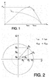
- Fig. 1 shows a graph of the power and the intensity of a solar panel against the voltage, where it may be observed that the power is at a maximum at a given voltage that is dependent on the atmospheric conditions (temperature and solar irradiation).
- the operating methods of solar generation systems are limited to constantly finding the maximum active power generation point.
- contingencies in the electrical network may occasionally make it advisable to reduce the active power generated and increase the reactive power.
- the inventors of this application have discovered that an adequate control of the inverter of a solar cell, taking into consideration the shape of the P-V curve, makes it possible to control the active power and the reactive power that are transmitted to the electrical network, thereby contributing to network stability in accordance with the conditions thereof at each time.
- an operating method for a solar generation system comprising at least one set of solar cells connected to an inverter that transmits the energy generated to an electrical network.
- an inverter controller may be implemented as a separate unit in the inverter, or be integrated therein.
- the method comprises controlling the active and reactive power that the system transmits to the electrical network by controlling the voltage of the solar cells and the inverter output current, such that, in a first mode of operation, the voltage of the solar cells provides the maximum active power, whereas, in a second mode of operation, the voltage in the solar cells provides an active power that is lower than the maximum.
- Fig. 2 shows a phase diagram where each vector corresponds to a given apparent power, which is respectively broken down into the sum of the vectors of the active power (abscissa axis) and the reactive power (ordinate axis).
- the apparent power transmitted by the solar generation system to the electrical network is the product of the voltage by the intensity.
- S V net ⁇ I inv
- the voltage is fixed, through the inverter, by the network voltage (V net ), whereas the intensity (I inv ) may be controlled by means of the inverter.
- the inverter is designed with a maximum output current (I invMAX ) and, consequently, at each time there is an available apparent power S avail that is dependent on the maximum output current and the network voltage.
- S avail V net ⁇ I invMAX
- the network voltage (V net ) may not remain constant.
- V net the network voltage
- the maximum reactive power (Q MAX ) is lower than the reactive power required to support the network, it is possible to increase said maximum reactive power (Q MAX ) by decreasing the active power by controlling the voltage in the cells. Since the network voltage is variable and, as described above, affects the available apparent power (S avail ), the comparison between the reactive power required and the maximum reactive power that may be generated must be regularly performed. This will be explained in more detail further below in this document by means of specific examples.
- the method of the invention comprises two modes of operation:
- Increasing the voltage in order to decrease the power generated instead of reducing it, has the advantage of involving lower intensities through the different devices that make up the system, thereby reducing the heating thereof and increasing their useful life.
- Another advantage is that the system is more stable if a capacitor (or condenser) is connected in parallel between the solar cells and the inverter. A sudden decrease in the active power generated by the solar cells will cause the condenser to become discharged, thereby decreasing the voltage, which consequently will come close to the maximum power voltage and the power generated by the solar cells will once again increase. Therefore, in this preferred embodiment, the operating area of the generation system will be located from the maximum power point toward the right in the P-V curve, as shown in Fig. 1 .
- switching from the first mode of operation to the second mode of operation comprises charging a capacitor arranged in parallel between the solar cells and the inverter, using, to this end, a part of the active power generated by the solar cells.
- switching from the second mode of operation to the first mode of operation preferably comprises discharging the capacitor, which transmits part of the energy stored to the electrical network through the inverter.
- the method described makes it possible for the solar cells to generate the maximum possible power in accordance with the operating conditions in the first mode of operation, and switches to the second mode of operation in response to different contingencies in the electrical network.
- switching to the second mode of operation will preferably take place when one of the following contingencies is detected:
- Another preferred embodiment of the invention is aimed at a control method for a generation plant formed by a plurality of solar generation systems by means of a central control unit.
- the central control unit sends signals to the different inverter controllers, determining the mode of operation of each on the basis of the network conditions.
- the solar generation systems it is possible for some of the solar generation systems to operate in the first mode of operation and for others to operate in the second mode of operation.
- a second aspect of the invention relates to a solar generation system that is capable of performing the method described above, comprising:
- the generation system additionally comprises a set of sensors that provide information about the electrical network condition and the solar cells to the inverter control unit.
- another particular embodiment of the invention comprises energy storage devices and, preferably, also a storage controller that co-ordinates the storage devices' charging and discharging operations, which may be electrical, chemical (batteries, hydrogen batteries, etc.), mechanical (flywheels, pumping of water, compressed air, etc.) devices.
- the presence of storage devices in the system of the invention opens numerous possibilities in regards to the operation thereof.
- the energy generated by the solar cells may be used, in whole or in part, to charge the storage devices.
- the storage devices may supply energy to the network in addition to that generated by the solar cells.
- the operation of the solar cells may also be co-ordinated by means of controllable loads, understanding an active charge to mean any type of charge susceptible to being controlled in order to bear a variable supply, for example, electrolysis equipment.
- Another example of an active charge is an installation designed to de-salt seawater.
- Another embodiment of the invention is aimed at a solar generation plant comprising a set of solar generation systems such as those described above, and which, moreover, comprises a central control unit that is connected to the inverter control units in order to transmit respective operation signals thereto on the basis of the electrical network conditions or the network operator requirements.
- a plant such as this may maximise energy production whenever possible and, moreover, provide additional services to the network when the latter so requires. Some of these services may be obtained by simultaneously combining, in the plant, solar generation systems operating in the first mode with other systems operating in the second mode.
- some systems are made to operate in the second mode of operation when the following contingencies occur:
- the central control unit will preferably send power limitation signals and/or power reduction signals to the inverter controllers.
- the solar generation systems will reduce the power generated, switching from the first to the second mode of operation, if they receive a power limitation signal or if they generate a power that is greater than the power limitation signal.
- the signals may be different for each of the generation systems, which results in advantageous features for the solar generation plant. For example, when a solar generation plant is required to maintain a power reduction with respect to the maximum power that it could generate (available active power) for a period of time, it is difficult to find out the current available active power value when said active power is being limited. Said available active power is variable and is dependent on at least the temperature, the solar irradiation and the dirt accumulated in the cells.
- the present invention proposes a mode of operation in the solar generation plant whereby some systems are in the first mode of operation and others are in the second mode of operation, and the maximum production that the entire plant (the available active power) could generate is estimated on the basis of the active power generated by the former; the active power signal for the rest of the systems is established on the basis of this value, such that the total power generated by the plant meets the active power limitation requirement.
- signals may be sent from the control unit in order to smooth the derivatives thereof: if a cloud enters the solar field, the systems in the first mode of operation will quickly reduce the active power generated, and the calculated available power will also decrease. In order to compensate for this effect, the central control unit may send signals to the systems operating in the second mode of operation so that they increase the power generated. In this manner, the variations in power are smoothed.
- FIG. 3 shows a diagram of a solar generation system (1) in accordance with the invention, where the different elements that make it up can be seen: a set of solar cells (2) connected to an inverter (4), which transmits the power generated to the electrical network (6).
- a controller (5) receives information about the electrical network (6) conditions and the voltage (V cell ) at terminals of the solar cells (2) in order to adequately control the inverter (4).
- a condenser (3) is placed in parallel between the solar cells (2) and the inverter (4), such that any variation in the voltage (V cell ) of the solar cells (2) leads to the charging and discharging thereof.
- FIG. 4 shows a simplified diagram of a solar generation plant (8) formed by a set of systems (1) like the preceding one.
- three systems (1) have been represented in parallel, each of which may be controlled from a central control unit (7) connected to each of the controllers (5) of the inverters (4) of the respective systems.
- Fig. 5 shows an example of the method of the invention that may be performed by a system (1) such as that in Fig. 3 .
- a system (1) such as that in Fig. 3 .
- S avail1 there is an available power S avail1 , generating an active power P 1 , which is the maximum possible active power under the current irradiance and temperature conditions, and a reactive power suitable for the electrical network (6) requirements at that time.
- apparent power S 1 is lower than available apparent power S avail1 .
- Fig. 6 shows another application example of the invention under similar starting conditions.
- the available power is S avail1 and an active power P 1 , which is the maximum possible power under those conditions, and a reactive power Q 1 are being generated.
- Apparent power S 1 is lower than the available apparent power.
- control unit (5) of the inverter (4) is capable of calculating the final reactive power instructions (Q ref ) on the basis of the electrical network (6) voltage as locally measured.
- control unit (5) comprises a conventional regulator which calculates the final reactive power instructions (Q ref ) on the basis of the difference between the measured voltage (V meas ) and a voltage signal (V ref ).
- the central control unit (7) measures the voltage (V cmeas ) or the power factor at the point where the solar generation plant (8) is connected to the electrical network (6) and, on the basis of this value, calculates the reactive power instructions for the different generation systems (1).
- the central control unit (7) comprises a conventional regulator that calculates the reactive power instructions (Q cref ) on the basis of the difference between the measured voltage or power factor and a voltage signal (V cref ) or power factor signal, and sends them to the control units (5) in the different generation systems (1).
- local control of the voltage at the generation system (1) level is combined with control of the voltage or power factor at the generation plant level (8), implemented by the central control unit (7).
- the instructions for the local voltage (V ref ) at the terminals of the generation system (1) are generated.
- the voltage controls in the generation system (1) are quick, in order to address sudden changes in voltage, whereas the voltage or power factor controls at the generation plant (8) level are slower and serve to adjust the performance of the entire plant (8).
- the generation of reactive power by a solar generation plant may be performed even in the absence of active generation, for example at night.
- the plant's (8) central control unit (7) makes a first group of systems (1) to operate in the first mode of operation and a second group of systems (1) to operate in the second mode of operation.
- the first group of systems (1) is composed of half the generation systems (1) that make up the plant (8), and, furthermore, that said first group is uniformly distributed throughout the plant (8).
- the available active power for the entire generation plant (8) may be quite accurately estimated as twice the active power produced by the first group of systems (1).
- the central control unit (7) calculates and sends active power reduction signals to the second group of systems (1). Taking up the preceding example, if a 2% power reduction is requested for the entire plant (8), signals will be sent to the systems (1) that make up the second group of systems (1) such that said second group produces, overall, 48% of the available active power in the entire plant (8). In this manner, adding the production of the two groups of systems (1), the result is 98% of the available active power, thereby fulfilling the operator's requirement.
Landscapes
- Engineering & Computer Science (AREA)
- Power Engineering (AREA)
- Supply And Distribution Of Alternating Current (AREA)
- Inverter Devices (AREA)
- Control Of Electrical Variables (AREA)
Priority Applications (1)
| Application Number | Priority Date | Filing Date | Title |
|---|---|---|---|
| CY20151100837T CY1116838T1 (el) | 2009-10-14 | 2015-09-23 | Μεθοδος και συστημα παραγωγης ενεργειας απο την ηλιακη ακτινοβολια |
Applications Claiming Priority (1)
| Application Number | Priority Date | Filing Date | Title |
|---|---|---|---|
| PCT/ES2009/070438 WO2011045447A1 (fr) | 2009-10-14 | 2009-10-14 | Procédé et système de génération solaire |
Publications (2)
| Publication Number | Publication Date |
|---|---|
| EP2490312A1 true EP2490312A1 (fr) | 2012-08-22 |
| EP2490312B1 EP2490312B1 (fr) | 2015-06-24 |
Family
ID=42363214
Family Applications (1)
| Application Number | Title | Priority Date | Filing Date |
|---|---|---|---|
| EP09751949.0A Active EP2490312B1 (fr) | 2009-10-14 | 2009-10-14 | Procédé et système de génération solaire |
Country Status (13)
| Country | Link |
|---|---|
| US (1) | US8982590B2 (fr) |
| EP (1) | EP2490312B1 (fr) |
| AU (1) | AU2009353975B2 (fr) |
| CA (1) | CA2777873C (fr) |
| CY (1) | CY1116838T1 (fr) |
| EG (1) | EG27169A (fr) |
| ES (1) | ES2548136T3 (fr) |
| MA (1) | MA33674B1 (fr) |
| MX (1) | MX2012004449A (fr) |
| PT (1) | PT2490312E (fr) |
| TN (1) | TN2012000173A1 (fr) |
| WO (1) | WO2011045447A1 (fr) |
| ZA (1) | ZA201202843B (fr) |
Cited By (6)
| Publication number | Priority date | Publication date | Assignee | Title |
|---|---|---|---|---|
| CN103346584A (zh) * | 2013-06-27 | 2013-10-09 | 深圳市汇川技术股份有限公司 | 光伏并网系统及功率补偿方法 |
| CN105576677A (zh) * | 2016-02-22 | 2016-05-11 | 华中科技大学 | 一种光伏储能系统能量管理控制方法 |
| CN106253334A (zh) * | 2016-08-19 | 2016-12-21 | 阳光电源股份有限公司 | 一种级联型光伏并网逆变器及其控制方法和控制装置 |
| CN107155382A (zh) * | 2015-01-13 | 2017-09-12 | 东芝三菱电机产业系统株式会社 | 逆变器的控制装置 |
| FR3060229A1 (fr) * | 2016-12-12 | 2018-06-15 | Electricite De France | Commande en puissance d'onduleurs d'une installation photovoltaique pour la participation au reglage en frequence du reseau de distribution electrique |
| WO2019170479A1 (fr) * | 2018-03-09 | 2019-09-12 | Sma Solar Technology Ag | Procédé servant à faire fonctionner une installation de production d'énergie, et onduleur pour une installation de production d'énergie |
Families Citing this family (16)
| Publication number | Priority date | Publication date | Assignee | Title |
|---|---|---|---|---|
| US8271599B2 (en) * | 2010-01-08 | 2012-09-18 | Tigo Energy, Inc. | Systems and methods for an identification protocol between a local controller and a master controller in a photovoltaic power generation system |
| CA2797823A1 (fr) * | 2010-04-29 | 2011-11-10 | Enphase Energy, Inc. | Procede et appareil pour production d'energie repartie |
| US8452461B2 (en) * | 2011-05-10 | 2013-05-28 | First Solar, Inc | Control system for photovoltaic power plant |
| US9270164B2 (en) | 2013-06-19 | 2016-02-23 | Tmeic Corporation | Methods, systems, computer program products, and devices for renewable energy site power limit control |
| US9728974B2 (en) | 2013-10-10 | 2017-08-08 | Tmeic Corporation | Renewable energy site reactive power control |
| WO2016055069A1 (fr) * | 2014-10-07 | 2016-04-14 | Vestas Wind Systems A/S | Support de puissance réactive à partir d'installations d'éoliennes |
| US10326277B2 (en) * | 2015-06-26 | 2019-06-18 | Enphase Energy, Inc. | Hierarchical control of a plurality of power subsystems and method of operating the same |
| WO2017037925A1 (fr) * | 2015-09-03 | 2017-03-09 | 株式会社東芝 | Dispositif et procédé de suppression de fluctuation de tension |
| CN106451560B (zh) * | 2016-11-29 | 2019-02-01 | 阳光电源股份有限公司 | 一种级联h桥并网逆变器mppt启动方法及主控制器 |
| JP6892191B2 (ja) * | 2017-03-02 | 2021-06-23 | 株式会社ダイヘン | 電力システム |
| AU2018366935B2 (en) * | 2017-11-16 | 2024-03-21 | Sma Solar Technology Ag | Feeding electric power from a photovoltaic system into an AC system having a low short-circuit capacity |
| CN108462211A (zh) * | 2018-05-10 | 2018-08-28 | 北京科诺伟业科技股份有限公司 | 一种提高分布式光伏系统自发自用率的方法 |
| US10886739B2 (en) | 2018-05-31 | 2021-01-05 | Trane International Inc. | Systems and methods for grid appliances |
| JP7202963B2 (ja) * | 2019-04-24 | 2023-01-12 | 株式会社日立製作所 | 太陽光発電設備の監視制御装置および制御方法 |
| CN114556259B (zh) * | 2019-12-12 | 2023-04-28 | 东芝三菱电机产业系统株式会社 | 电力转换装置 |
| US20220244298A1 (en) * | 2021-01-29 | 2022-08-04 | Korea University Research And Business Foundation | Device and method for extracting electric network frequency |
Family Cites Families (5)
| Publication number | Priority date | Publication date | Assignee | Title |
|---|---|---|---|---|
| US3384806A (en) * | 1964-10-16 | 1968-05-21 | Honeywell Inc | Power conditioing system |
| CN1161678C (zh) * | 1998-03-30 | 2004-08-11 | 三洋电机株式会社 | 太阳能发电装置 |
| US20080036440A1 (en) * | 2004-06-24 | 2008-02-14 | Ambient Control Systems, Inc. | Systems and Methods for Providing Maximum Photovoltaic Peak Power Tracking |
| US7193872B2 (en) * | 2005-01-28 | 2007-03-20 | Kasemsan Siri | Solar array inverter with maximum power tracking |
| US8159178B2 (en) * | 2009-08-21 | 2012-04-17 | Xantrex Technology Inc. | AC connected modules with line frequency or voltage variation pattern for energy control |
-
2009
- 2009-10-14 PT PT97519490T patent/PT2490312E/pt unknown
- 2009-10-14 US US13/501,979 patent/US8982590B2/en active Active
- 2009-10-14 CA CA2777873A patent/CA2777873C/fr active Active
- 2009-10-14 ES ES09751949.0T patent/ES2548136T3/es active Active
- 2009-10-14 EP EP09751949.0A patent/EP2490312B1/fr active Active
- 2009-10-14 WO PCT/ES2009/070438 patent/WO2011045447A1/fr active Application Filing
- 2009-10-14 MX MX2012004449A patent/MX2012004449A/es active IP Right Grant
- 2009-10-14 AU AU2009353975A patent/AU2009353975B2/en active Active
-
2012
- 2012-04-13 MA MA34778A patent/MA33674B1/fr unknown
- 2012-04-13 TN TNP2012000173A patent/TN2012000173A1/en unknown
- 2012-04-18 ZA ZA2012/02843A patent/ZA201202843B/en unknown
- 2012-09-15 EG EG2012090696A patent/EG27169A/xx active
-
2015
- 2015-09-23 CY CY20151100837T patent/CY1116838T1/el unknown
Non-Patent Citations (1)
| Title |
|---|
| See references of WO2011045447A1 * |
Cited By (14)
| Publication number | Priority date | Publication date | Assignee | Title |
|---|---|---|---|---|
| CN103346584A (zh) * | 2013-06-27 | 2013-10-09 | 深圳市汇川技术股份有限公司 | 光伏并网系统及功率补偿方法 |
| CN107155382A (zh) * | 2015-01-13 | 2017-09-12 | 东芝三菱电机产业系统株式会社 | 逆变器的控制装置 |
| EP3247018A4 (fr) * | 2015-01-13 | 2018-10-24 | Toshiba Mitsubishi-Electric Industrial Systems Corporation | Dispositif de commande pour onduleur |
| CN105576677B (zh) * | 2016-02-22 | 2018-04-10 | 华中科技大学 | 一种光伏储能系统能量管理控制方法 |
| CN105576677A (zh) * | 2016-02-22 | 2016-05-11 | 华中科技大学 | 一种光伏储能系统能量管理控制方法 |
| CN106253334B (zh) * | 2016-08-19 | 2018-12-28 | 阳光电源股份有限公司 | 一种级联型光伏并网逆变器及其控制方法和控制装置 |
| EP3285350A1 (fr) * | 2016-08-19 | 2018-02-21 | Sungrow Power Supply Co., Ltd. | Onduleur photovoltaïque en cascade raccordé au réseau, son procédé de commande et son dispositif de commande |
| CN106253334A (zh) * | 2016-08-19 | 2016-12-21 | 阳光电源股份有限公司 | 一种级联型光伏并网逆变器及其控制方法和控制装置 |
| US10361640B2 (en) | 2016-08-19 | 2019-07-23 | Sungrow Power Supply Co., Ltd. | Cascaded photovoltaic grid-connected inverter, control method and control device for the same |
| FR3060229A1 (fr) * | 2016-12-12 | 2018-06-15 | Electricite De France | Commande en puissance d'onduleurs d'une installation photovoltaique pour la participation au reglage en frequence du reseau de distribution electrique |
| WO2018108481A1 (fr) * | 2016-12-12 | 2018-06-21 | Electricite De France | Commande en puissance d'onduleurs d'une installation photovoltaïque pour la participation au réglage en fréquence du réseau de distribution électrique |
| US10790673B2 (en) | 2016-12-12 | 2020-09-29 | Electricite De France | Power control of inverters of a photovoltaic facility in order to participate in frequency regulation of the electrical distribution network |
| WO2019170479A1 (fr) * | 2018-03-09 | 2019-09-12 | Sma Solar Technology Ag | Procédé servant à faire fonctionner une installation de production d'énergie, et onduleur pour une installation de production d'énergie |
| JP2021516391A (ja) * | 2018-03-09 | 2021-07-01 | エスエムエイ ソーラー テクノロジー アクティエンゲゼルシャフトSMA Solar Technology AG | エネルギー生成システムの動作方法及びエネルギー生成システム用のインバータ |
Also Published As
| Publication number | Publication date |
|---|---|
| US8982590B2 (en) | 2015-03-17 |
| AU2009353975A1 (en) | 2012-05-10 |
| MA33674B1 (fr) | 2012-10-01 |
| EP2490312B1 (fr) | 2015-06-24 |
| AU2009353975B2 (en) | 2015-12-24 |
| CA2777873A1 (fr) | 2011-04-21 |
| EG27169A (en) | 2015-08-30 |
| US20120262960A1 (en) | 2012-10-18 |
| WO2011045447A1 (fr) | 2011-04-21 |
| TN2012000173A1 (en) | 2013-12-12 |
| ZA201202843B (en) | 2012-12-27 |
| CA2777873C (fr) | 2017-02-07 |
| CY1116838T1 (el) | 2017-03-15 |
| ES2548136T3 (es) | 2015-10-14 |
| MX2012004449A (es) | 2012-05-08 |
| PT2490312E (pt) | 2015-10-19 |
Similar Documents
| Publication | Publication Date | Title |
|---|---|---|
| EP2490312B1 (fr) | Procédé et système de génération solaire | |
| EP3148037B1 (fr) | Systeme de stockage d'energie | |
| US8766590B2 (en) | Energy storage system of apartment building, integrated power management system, and method of controlling the system | |
| US8901893B2 (en) | Electricity storage device and hybrid distributed power supply system | |
| KR20130104771A (ko) | 에너지 저장 시스템 및 그의 제어 방법 | |
| CN110176788B (zh) | 蓄电系统以及蓄电装置 | |
| JP6828567B2 (ja) | 系統連系システムおよび電力システム | |
| JP6821904B2 (ja) | 電力システム | |
| RU2568013C2 (ru) | Система выработки энергии и способ ее эксплуатации | |
| US20220263311A1 (en) | System and Method for Managing Power | |
| KR101644522B1 (ko) | Ac 마이크로그리드 3상부하에서의 전력 공급 시스템 | |
| JP2023138478A (ja) | 高い動的負荷を有する電力システムのバッテリエネルギー貯蔵システムを制御する方法 | |
| JP6821905B2 (ja) | 電力システム | |
| JP6892191B2 (ja) | 電力システム | |
| Nakamura et al. | Green base station using robust solar system and high performance lithium ion battery for next generation wireless network (5G) and against mega disaster | |
| CN106786803A (zh) | 独立运行光伏发电系统供大于需时的一种无损功率平衡法 | |
| US11929621B2 (en) | Power control apparatus, control method for power control apparatus, and distributed power generating system | |
| RU2726943C1 (ru) | Способ снижения расхода топлива дизель-генераторными установками в гибридной электростанции с возобновляемыми источниками энергии | |
| Rama et al. | Energy management system with a reduced sensor for DC microgrid | |
| WO2015036950A1 (fr) | Plate-forme de distribution d'énergie électrique | |
| US11901807B2 (en) | Bypass circuit, power system control method, and non-transitory computer readable medium | |
| WO2014019605A1 (fr) | Installation pour commander un courant de charge pour des unités de stockage dans des réseaux d'alimentation d'énergie électrique connectant des générateurs distribués et des unités de stockage distribuées, entre autres | |
| KR102273044B1 (ko) | 직류 공통 방식을 이용한 하이브리드 신재생 에너지 시스템 | |
| JP7181160B2 (ja) | 発電制御装置、発電制御方法および再生可能エネルギーハイブリッド発電システム | |
| Chakraborty et al. | Coordinated Frequency Based Demand Side Management Scheme with Active Power Curtailment of Solar PV in a Battery Hybrid Stand-Alone Microgrid |
Legal Events
| Date | Code | Title | Description |
|---|---|---|---|
| PUAI | Public reference made under article 153(3) epc to a published international application that has entered the european phase |
Free format text: ORIGINAL CODE: 0009012 |
|
| 17P | Request for examination filed |
Effective date: 20120427 |
|
| AK | Designated contracting states |
Kind code of ref document: A1 Designated state(s): AT BE BG CH CY CZ DE DK EE ES FI FR GB GR HR HU IE IS IT LI LT LU LV MC MK MT NL NO PL PT RO SE SI SK SM TR |
|
| DAX | Request for extension of the european patent (deleted) | ||
| GRAP | Despatch of communication of intention to grant a patent |
Free format text: ORIGINAL CODE: EPIDOSNIGR1 |
|
| INTG | Intention to grant announced |
Effective date: 20150313 |
|
| GRAS | Grant fee paid |
Free format text: ORIGINAL CODE: EPIDOSNIGR3 |
|
| GRAA | (expected) grant |
Free format text: ORIGINAL CODE: 0009210 |
|
| AK | Designated contracting states |
Kind code of ref document: B1 Designated state(s): AT BE BG CH CY CZ DE DK EE ES FI FR GB GR HR HU IE IS IT LI LT LU LV MC MK MT NL NO PL PT RO SE SI SK SM TR |
|
| REG | Reference to a national code |
Ref country code: GB Ref legal event code: FG4D |
|
| REG | Reference to a national code |
Ref country code: CH Ref legal event code: EP |
|
| REG | Reference to a national code |
Ref country code: AT Ref legal event code: REF Ref document number: 733282 Country of ref document: AT Kind code of ref document: T Effective date: 20150715 |
|
| REG | Reference to a national code |
Ref country code: IE Ref legal event code: FG4D |
|
| REG | Reference to a national code |
Ref country code: DE Ref legal event code: R096 Ref document number: 602009031864 Country of ref document: DE |
|
| REG | Reference to a national code |
Ref country code: ES Ref legal event code: FG2A Ref document number: 2548136 Country of ref document: ES Kind code of ref document: T3 Effective date: 20151014 |
|
| REG | Reference to a national code |
Ref country code: FR Ref legal event code: PLFP Year of fee payment: 7 Ref country code: PT Ref legal event code: SC4A Free format text: AVAILABILITY OF NATIONAL TRANSLATION Effective date: 20150923 |
|
| PG25 | Lapsed in a contracting state [announced via postgrant information from national office to epo] |
Ref country code: HR Free format text: LAPSE BECAUSE OF FAILURE TO SUBMIT A TRANSLATION OF THE DESCRIPTION OR TO PAY THE FEE WITHIN THE PRESCRIBED TIME-LIMIT Effective date: 20150624 Ref country code: NO Free format text: LAPSE BECAUSE OF FAILURE TO SUBMIT A TRANSLATION OF THE DESCRIPTION OR TO PAY THE FEE WITHIN THE PRESCRIBED TIME-LIMIT Effective date: 20150924 Ref country code: LT Free format text: LAPSE BECAUSE OF FAILURE TO SUBMIT A TRANSLATION OF THE DESCRIPTION OR TO PAY THE FEE WITHIN THE PRESCRIBED TIME-LIMIT Effective date: 20150624 Ref country code: FI Free format text: LAPSE BECAUSE OF FAILURE TO SUBMIT A TRANSLATION OF THE DESCRIPTION OR TO PAY THE FEE WITHIN THE PRESCRIBED TIME-LIMIT Effective date: 20150624 |
|
| REG | Reference to a national code |
Ref country code: AT Ref legal event code: MK05 Ref document number: 733282 Country of ref document: AT Kind code of ref document: T Effective date: 20150624 |
|
| REG | Reference to a national code |
Ref country code: LT Ref legal event code: MG4D |
|
| PG25 | Lapsed in a contracting state [announced via postgrant information from national office to epo] |
Ref country code: LV Free format text: LAPSE BECAUSE OF FAILURE TO SUBMIT A TRANSLATION OF THE DESCRIPTION OR TO PAY THE FEE WITHIN THE PRESCRIBED TIME-LIMIT Effective date: 20150624 Ref country code: BG Free format text: LAPSE BECAUSE OF FAILURE TO SUBMIT A TRANSLATION OF THE DESCRIPTION OR TO PAY THE FEE WITHIN THE PRESCRIBED TIME-LIMIT Effective date: 20150924 |
|
| REG | Reference to a national code |
Ref country code: NL Ref legal event code: MP Effective date: 20150624 |
|
| REG | Reference to a national code |
Ref country code: GR Ref legal event code: EP Ref document number: 20150401945 Country of ref document: GR Effective date: 20151022 |
|
| PG25 | Lapsed in a contracting state [announced via postgrant information from national office to epo] |
Ref country code: EE Free format text: LAPSE BECAUSE OF FAILURE TO SUBMIT A TRANSLATION OF THE DESCRIPTION OR TO PAY THE FEE WITHIN THE PRESCRIBED TIME-LIMIT Effective date: 20150624 |
|
| PG25 | Lapsed in a contracting state [announced via postgrant information from national office to epo] |
Ref country code: IS Free format text: LAPSE BECAUSE OF FAILURE TO SUBMIT A TRANSLATION OF THE DESCRIPTION OR TO PAY THE FEE WITHIN THE PRESCRIBED TIME-LIMIT Effective date: 20151024 Ref country code: CZ Free format text: LAPSE BECAUSE OF FAILURE TO SUBMIT A TRANSLATION OF THE DESCRIPTION OR TO PAY THE FEE WITHIN THE PRESCRIBED TIME-LIMIT Effective date: 20150624 Ref country code: SK Free format text: LAPSE BECAUSE OF FAILURE TO SUBMIT A TRANSLATION OF THE DESCRIPTION OR TO PAY THE FEE WITHIN THE PRESCRIBED TIME-LIMIT Effective date: 20150624 Ref country code: AT Free format text: LAPSE BECAUSE OF FAILURE TO SUBMIT A TRANSLATION OF THE DESCRIPTION OR TO PAY THE FEE WITHIN THE PRESCRIBED TIME-LIMIT Effective date: 20150624 Ref country code: PL Free format text: LAPSE BECAUSE OF FAILURE TO SUBMIT A TRANSLATION OF THE DESCRIPTION OR TO PAY THE FEE WITHIN THE PRESCRIBED TIME-LIMIT Effective date: 20150624 Ref country code: RO Free format text: LAPSE BECAUSE OF NON-PAYMENT OF DUE FEES Effective date: 20150624 |
|
| REG | Reference to a national code |
Ref country code: DE Ref legal event code: R097 Ref document number: 602009031864 Country of ref document: DE |
|
| PG25 | Lapsed in a contracting state [announced via postgrant information from national office to epo] |
Ref country code: DK Free format text: LAPSE BECAUSE OF FAILURE TO SUBMIT A TRANSLATION OF THE DESCRIPTION OR TO PAY THE FEE WITHIN THE PRESCRIBED TIME-LIMIT Effective date: 20150624 |
|
| PLBE | No opposition filed within time limit |
Free format text: ORIGINAL CODE: 0009261 |
|
| STAA | Information on the status of an ep patent application or granted ep patent |
Free format text: STATUS: NO OPPOSITION FILED WITHIN TIME LIMIT |
|
| PG25 | Lapsed in a contracting state [announced via postgrant information from national office to epo] |
Ref country code: LU Free format text: LAPSE BECAUSE OF FAILURE TO SUBMIT A TRANSLATION OF THE DESCRIPTION OR TO PAY THE FEE WITHIN THE PRESCRIBED TIME-LIMIT Effective date: 20151014 |
|
| REG | Reference to a national code |
Ref country code: CH Ref legal event code: PL |
|
| 26N | No opposition filed |
Effective date: 20160329 |
|
| PG25 | Lapsed in a contracting state [announced via postgrant information from national office to epo] |
Ref country code: MC Free format text: LAPSE BECAUSE OF FAILURE TO SUBMIT A TRANSLATION OF THE DESCRIPTION OR TO PAY THE FEE WITHIN THE PRESCRIBED TIME-LIMIT Effective date: 20150624 |
|
| REG | Reference to a national code |
Ref country code: IE Ref legal event code: MM4A |
|
| PG25 | Lapsed in a contracting state [announced via postgrant information from national office to epo] |
Ref country code: CH Free format text: LAPSE BECAUSE OF NON-PAYMENT OF DUE FEES Effective date: 20151031 Ref country code: LI Free format text: LAPSE BECAUSE OF NON-PAYMENT OF DUE FEES Effective date: 20151031 |
|
| PG25 | Lapsed in a contracting state [announced via postgrant information from national office to epo] |
Ref country code: SI Free format text: LAPSE BECAUSE OF FAILURE TO SUBMIT A TRANSLATION OF THE DESCRIPTION OR TO PAY THE FEE WITHIN THE PRESCRIBED TIME-LIMIT Effective date: 20150624 |
|
| REG | Reference to a national code |
Ref country code: FR Ref legal event code: PLFP Year of fee payment: 8 |
|
| PG25 | Lapsed in a contracting state [announced via postgrant information from national office to epo] |
Ref country code: IE Free format text: LAPSE BECAUSE OF NON-PAYMENT OF DUE FEES Effective date: 20151014 |
|
| PG25 | Lapsed in a contracting state [announced via postgrant information from national office to epo] |
Ref country code: BE Free format text: LAPSE BECAUSE OF FAILURE TO SUBMIT A TRANSLATION OF THE DESCRIPTION OR TO PAY THE FEE WITHIN THE PRESCRIBED TIME-LIMIT Effective date: 20150624 |
|
| PG25 | Lapsed in a contracting state [announced via postgrant information from national office to epo] |
Ref country code: HU Free format text: LAPSE BECAUSE OF FAILURE TO SUBMIT A TRANSLATION OF THE DESCRIPTION OR TO PAY THE FEE WITHIN THE PRESCRIBED TIME-LIMIT; INVALID AB INITIO Effective date: 20091014 Ref country code: SM Free format text: LAPSE BECAUSE OF FAILURE TO SUBMIT A TRANSLATION OF THE DESCRIPTION OR TO PAY THE FEE WITHIN THE PRESCRIBED TIME-LIMIT Effective date: 20150624 |
|
| PG25 | Lapsed in a contracting state [announced via postgrant information from national office to epo] |
Ref country code: SE Free format text: LAPSE BECAUSE OF FAILURE TO SUBMIT A TRANSLATION OF THE DESCRIPTION OR TO PAY THE FEE WITHIN THE PRESCRIBED TIME-LIMIT Effective date: 20150624 Ref country code: NL Free format text: LAPSE BECAUSE OF FAILURE TO SUBMIT A TRANSLATION OF THE DESCRIPTION OR TO PAY THE FEE WITHIN THE PRESCRIBED TIME-LIMIT Effective date: 20150624 |
|
| REG | Reference to a national code |
Ref country code: FR Ref legal event code: PLFP Year of fee payment: 9 |
|
| PG25 | Lapsed in a contracting state [announced via postgrant information from national office to epo] |
Ref country code: MK Free format text: LAPSE BECAUSE OF FAILURE TO SUBMIT A TRANSLATION OF THE DESCRIPTION OR TO PAY THE FEE WITHIN THE PRESCRIBED TIME-LIMIT Effective date: 20150624 |
|
| REG | Reference to a national code |
Ref country code: FR Ref legal event code: PLFP Year of fee payment: 10 |
|
| REG | Reference to a national code |
Ref country code: DE Ref legal event code: R081 Ref document number: 602009031864 Country of ref document: DE Owner name: ACCIONA GENERACION RENOVABLE, S.A., SARRIGUREN, ES Free format text: FORMER OWNER: ACCIONA ENERGIA, S.A., SARRIGUREN, NAVARRA, ES |
|
| P01 | Opt-out of the competence of the unified patent court (upc) registered |
Effective date: 20230526 |
|
| PGFP | Annual fee paid to national office [announced via postgrant information from national office to epo] |
Ref country code: TR Payment date: 20230928 Year of fee payment: 15 |
|
| PGFP | Annual fee paid to national office [announced via postgrant information from national office to epo] |
Ref country code: PT Payment date: 20230927 Year of fee payment: 15 |
|
| PGFP | Annual fee paid to national office [announced via postgrant information from national office to epo] |
Ref country code: MT Payment date: 20230919 Year of fee payment: 15 |
|
| PGFP | Annual fee paid to national office [announced via postgrant information from national office to epo] |
Ref country code: GR Payment date: 20231027 Year of fee payment: 15 Ref country code: GB Payment date: 20231027 Year of fee payment: 15 |
|
| PGFP | Annual fee paid to national office [announced via postgrant information from national office to epo] |
Ref country code: ES Payment date: 20231106 Year of fee payment: 15 |
|
| PGFP | Annual fee paid to national office [announced via postgrant information from national office to epo] |
Ref country code: IT Payment date: 20231023 Year of fee payment: 15 Ref country code: FR Payment date: 20231025 Year of fee payment: 15 Ref country code: DE Payment date: 20231027 Year of fee payment: 15 Ref country code: CY Payment date: 20230920 Year of fee payment: 15 |