EP2490289B2 - Brennstoffzellensystem - Google Patents
Brennstoffzellensystem Download PDFInfo
- Publication number
- EP2490289B2 EP2490289B2 EP12000970.9A EP12000970A EP2490289B2 EP 2490289 B2 EP2490289 B2 EP 2490289B2 EP 12000970 A EP12000970 A EP 12000970A EP 2490289 B2 EP2490289 B2 EP 2490289B2
- Authority
- EP
- European Patent Office
- Prior art keywords
- catalyst
- fuel cell
- gas
- cathode
- anode
- Prior art date
- Legal status (The legal status is an assumption and is not a legal conclusion. Google has not performed a legal analysis and makes no representation as to the accuracy of the status listed.)
- Not-in-force
Links
- 239000000446 fuel Substances 0.000 title claims description 58
- 239000003054 catalyst Substances 0.000 claims description 54
- 238000006243 chemical reaction Methods 0.000 claims description 14
- 239000000463 material Substances 0.000 claims description 7
- 238000002156 mixing Methods 0.000 claims description 6
- 229910000831 Steel Inorganic materials 0.000 claims description 3
- 238000003980 solgel method Methods 0.000 claims description 3
- 229910001220 stainless steel Inorganic materials 0.000 claims description 3
- 239000010935 stainless steel Substances 0.000 claims description 3
- 239000010959 steel Substances 0.000 claims description 3
- 239000007789 gas Substances 0.000 description 49
- 239000003570 air Substances 0.000 description 32
- BASFCYQUMIYNBI-UHFFFAOYSA-N platinum Chemical compound [Pt] BASFCYQUMIYNBI-UHFFFAOYSA-N 0.000 description 24
- KDLHZDBZIXYQEI-UHFFFAOYSA-N Palladium Chemical compound [Pd] KDLHZDBZIXYQEI-UHFFFAOYSA-N 0.000 description 16
- 230000003197 catalytic effect Effects 0.000 description 14
- UFHFLCQGNIYNRP-UHFFFAOYSA-N Hydrogen Chemical compound [H][H] UFHFLCQGNIYNRP-UHFFFAOYSA-N 0.000 description 12
- QVGXLLKOCUKJST-UHFFFAOYSA-N atomic oxygen Chemical compound [O] QVGXLLKOCUKJST-UHFFFAOYSA-N 0.000 description 12
- 239000001257 hydrogen Substances 0.000 description 12
- 229910052739 hydrogen Inorganic materials 0.000 description 12
- 239000001301 oxygen Substances 0.000 description 12
- 229910052760 oxygen Inorganic materials 0.000 description 12
- 229910052697 platinum Inorganic materials 0.000 description 12
- 238000002485 combustion reaction Methods 0.000 description 8
- VNWKTOKETHGBQD-UHFFFAOYSA-N methane Chemical compound C VNWKTOKETHGBQD-UHFFFAOYSA-N 0.000 description 8
- 229910052763 palladium Inorganic materials 0.000 description 8
- 239000002737 fuel gas Substances 0.000 description 7
- 230000000694 effects Effects 0.000 description 5
- CURLTUGMZLYLDI-UHFFFAOYSA-N Carbon dioxide Chemical compound O=C=O CURLTUGMZLYLDI-UHFFFAOYSA-N 0.000 description 4
- KJTLSVCANCCWHF-UHFFFAOYSA-N Ruthenium Chemical compound [Ru] KJTLSVCANCCWHF-UHFFFAOYSA-N 0.000 description 4
- 238000000034 method Methods 0.000 description 4
- 239000003345 natural gas Substances 0.000 description 4
- 230000003647 oxidation Effects 0.000 description 4
- 238000007254 oxidation reaction Methods 0.000 description 4
- 239000011224 oxide ceramic Substances 0.000 description 4
- 229910052574 oxide ceramic Inorganic materials 0.000 description 4
- 229910052707 ruthenium Inorganic materials 0.000 description 4
- 238000000629 steam reforming Methods 0.000 description 4
- 238000006555 catalytic reaction Methods 0.000 description 3
- 230000005611 electricity Effects 0.000 description 3
- 238000010438 heat treatment Methods 0.000 description 3
- 230000008569 process Effects 0.000 description 3
- XLYOFNOQVPJJNP-UHFFFAOYSA-N water Substances O XLYOFNOQVPJJNP-UHFFFAOYSA-N 0.000 description 3
- IJGRMHOSHXDMSA-UHFFFAOYSA-N Atomic nitrogen Chemical compound N#N IJGRMHOSHXDMSA-UHFFFAOYSA-N 0.000 description 2
- UGFAIRIUMAVXCW-UHFFFAOYSA-N Carbon monoxide Chemical compound [O+]#[C-] UGFAIRIUMAVXCW-UHFFFAOYSA-N 0.000 description 2
- 230000004913 activation Effects 0.000 description 2
- 239000012080 ambient air Substances 0.000 description 2
- 230000008901 benefit Effects 0.000 description 2
- 229910002092 carbon dioxide Inorganic materials 0.000 description 2
- 239000001569 carbon dioxide Substances 0.000 description 2
- 229910002091 carbon monoxide Inorganic materials 0.000 description 2
- 238000010304 firing Methods 0.000 description 2
- 238000002309 gasification Methods 0.000 description 2
- 229910052746 lanthanum Inorganic materials 0.000 description 2
- FZLIPJUXYLNCLC-UHFFFAOYSA-N lanthanum atom Chemical compound [La] FZLIPJUXYLNCLC-UHFFFAOYSA-N 0.000 description 2
- 239000003915 liquefied petroleum gas Substances 0.000 description 2
- 239000000203 mixture Substances 0.000 description 2
- 229910000510 noble metal Inorganic materials 0.000 description 2
- 239000003921 oil Substances 0.000 description 2
- 239000007800 oxidant agent Substances 0.000 description 2
- 230000009467 reduction Effects 0.000 description 2
- 238000002407 reforming Methods 0.000 description 2
- 229910052703 rhodium Inorganic materials 0.000 description 2
- 239000010948 rhodium Substances 0.000 description 2
- MHOVAHRLVXNVSD-UHFFFAOYSA-N rhodium atom Chemical compound [Rh] MHOVAHRLVXNVSD-UHFFFAOYSA-N 0.000 description 2
- 238000005245 sintering Methods 0.000 description 2
- 239000002918 waste heat Substances 0.000 description 2
- 239000002023 wood Substances 0.000 description 2
- 239000004215 Carbon black (E152) Substances 0.000 description 1
- 239000002318 adhesion promoter Substances 0.000 description 1
- 230000000035 biogenic effect Effects 0.000 description 1
- 238000004140 cleaning Methods 0.000 description 1
- 239000003245 coal Substances 0.000 description 1
- 238000000576 coating method Methods 0.000 description 1
- 239000000470 constituent Substances 0.000 description 1
- 230000007423 decrease Effects 0.000 description 1
- 230000007812 deficiency Effects 0.000 description 1
- 238000005516 engineering process Methods 0.000 description 1
- 239000002803 fossil fuel Substances 0.000 description 1
- 229930195733 hydrocarbon Natural products 0.000 description 1
- 150000002430 hydrocarbons Chemical class 0.000 description 1
- 230000007246 mechanism Effects 0.000 description 1
- 239000003863 metallic catalyst Substances 0.000 description 1
- 229910052757 nitrogen Inorganic materials 0.000 description 1
- 238000013021 overheating Methods 0.000 description 1
- 238000010248 power generation Methods 0.000 description 1
- 239000007858 starting material Substances 0.000 description 1
- 239000000126 substance Substances 0.000 description 1
- 238000011144 upstream manufacturing Methods 0.000 description 1
Images
Classifications
-
- B—PERFORMING OPERATIONS; TRANSPORTING
- B01—PHYSICAL OR CHEMICAL PROCESSES OR APPARATUS IN GENERAL
- B01J—CHEMICAL OR PHYSICAL PROCESSES, e.g. CATALYSIS OR COLLOID CHEMISTRY; THEIR RELEVANT APPARATUS
- B01J37/00—Processes, in general, for preparing catalysts; Processes, in general, for activation of catalysts
- B01J37/02—Impregnation, coating or precipitation
- B01J37/0215—Coating
- B01J37/0225—Coating of metal substrates
-
- B—PERFORMING OPERATIONS; TRANSPORTING
- B01—PHYSICAL OR CHEMICAL PROCESSES OR APPARATUS IN GENERAL
- B01J—CHEMICAL OR PHYSICAL PROCESSES, e.g. CATALYSIS OR COLLOID CHEMISTRY; THEIR RELEVANT APPARATUS
- B01J23/00—Catalysts comprising metals or metal oxides or hydroxides, not provided for in group B01J21/00
- B01J23/38—Catalysts comprising metals or metal oxides or hydroxides, not provided for in group B01J21/00 of noble metals
- B01J23/40—Catalysts comprising metals or metal oxides or hydroxides, not provided for in group B01J21/00 of noble metals of the platinum group metals
-
- H—ELECTRICITY
- H01—ELECTRIC ELEMENTS
- H01M—PROCESSES OR MEANS, e.g. BATTERIES, FOR THE DIRECT CONVERSION OF CHEMICAL ENERGY INTO ELECTRICAL ENERGY
- H01M8/00—Fuel cells; Manufacture thereof
- H01M8/04—Auxiliary arrangements, e.g. for control of pressure or for circulation of fluids
- H01M8/04007—Auxiliary arrangements, e.g. for control of pressure or for circulation of fluids related to heat exchange
- H01M8/04014—Heat exchange using gaseous fluids; Heat exchange by combustion of reactants
- H01M8/04022—Heating by combustion
-
- H—ELECTRICITY
- H01—ELECTRIC ELEMENTS
- H01M—PROCESSES OR MEANS, e.g. BATTERIES, FOR THE DIRECT CONVERSION OF CHEMICAL ENERGY INTO ELECTRICAL ENERGY
- H01M8/00—Fuel cells; Manufacture thereof
- H01M8/04—Auxiliary arrangements, e.g. for control of pressure or for circulation of fluids
- H01M8/04298—Processes for controlling fuel cells or fuel cell systems
- H01M8/04694—Processes for controlling fuel cells or fuel cell systems characterised by variables to be controlled
- H01M8/04701—Temperature
- H01M8/04716—Temperature of fuel cell exhausts
-
- H—ELECTRICITY
- H01—ELECTRIC ELEMENTS
- H01M—PROCESSES OR MEANS, e.g. BATTERIES, FOR THE DIRECT CONVERSION OF CHEMICAL ENERGY INTO ELECTRICAL ENERGY
- H01M8/00—Fuel cells; Manufacture thereof
- H01M8/04—Auxiliary arrangements, e.g. for control of pressure or for circulation of fluids
- H01M8/04298—Processes for controlling fuel cells or fuel cell systems
- H01M8/04694—Processes for controlling fuel cells or fuel cell systems characterised by variables to be controlled
- H01M8/04701—Temperature
- H01M8/04738—Temperature of auxiliary devices, e.g. reformer, compressor, burner
-
- H—ELECTRICITY
- H01—ELECTRIC ELEMENTS
- H01M—PROCESSES OR MEANS, e.g. BATTERIES, FOR THE DIRECT CONVERSION OF CHEMICAL ENERGY INTO ELECTRICAL ENERGY
- H01M8/00—Fuel cells; Manufacture thereof
- H01M8/06—Combination of fuel cells with means for production of reactants or for treatment of residues
- H01M8/0606—Combination of fuel cells with means for production of reactants or for treatment of residues with means for production of gaseous reactants
- H01M8/0612—Combination of fuel cells with means for production of reactants or for treatment of residues with means for production of gaseous reactants from carbon-containing material
-
- H—ELECTRICITY
- H01—ELECTRIC ELEMENTS
- H01M—PROCESSES OR MEANS, e.g. BATTERIES, FOR THE DIRECT CONVERSION OF CHEMICAL ENERGY INTO ELECTRICAL ENERGY
- H01M8/00—Fuel cells; Manufacture thereof
- H01M8/06—Combination of fuel cells with means for production of reactants or for treatment of residues
- H01M8/0662—Treatment of gaseous reactants or gaseous residues, e.g. cleaning
-
- B—PERFORMING OPERATIONS; TRANSPORTING
- B01—PHYSICAL OR CHEMICAL PROCESSES OR APPARATUS IN GENERAL
- B01D—SEPARATION
- B01D2255/00—Catalysts
- B01D2255/10—Noble metals or compounds thereof
- B01D2255/102—Platinum group metals
- B01D2255/1021—Platinum
-
- B—PERFORMING OPERATIONS; TRANSPORTING
- B01—PHYSICAL OR CHEMICAL PROCESSES OR APPARATUS IN GENERAL
- B01D—SEPARATION
- B01D2255/00—Catalysts
- B01D2255/10—Noble metals or compounds thereof
- B01D2255/102—Platinum group metals
- B01D2255/1023—Palladium
-
- B—PERFORMING OPERATIONS; TRANSPORTING
- B01—PHYSICAL OR CHEMICAL PROCESSES OR APPARATUS IN GENERAL
- B01D—SEPARATION
- B01D2255/00—Catalysts
- B01D2255/10—Noble metals or compounds thereof
- B01D2255/102—Platinum group metals
- B01D2255/1025—Rhodium
-
- B—PERFORMING OPERATIONS; TRANSPORTING
- B01—PHYSICAL OR CHEMICAL PROCESSES OR APPARATUS IN GENERAL
- B01D—SEPARATION
- B01D2255/00—Catalysts
- B01D2255/10—Noble metals or compounds thereof
- B01D2255/102—Platinum group metals
- B01D2255/1026—Ruthenium
-
- B—PERFORMING OPERATIONS; TRANSPORTING
- B01—PHYSICAL OR CHEMICAL PROCESSES OR APPARATUS IN GENERAL
- B01D—SEPARATION
- B01D2255/00—Catalysts
- B01D2255/20—Metals or compounds thereof
- B01D2255/206—Rare earth metals
- B01D2255/2063—Lanthanum
-
- B—PERFORMING OPERATIONS; TRANSPORTING
- B01—PHYSICAL OR CHEMICAL PROCESSES OR APPARATUS IN GENERAL
- B01D—SEPARATION
- B01D53/00—Separation of gases or vapours; Recovering vapours of volatile solvents from gases; Chemical or biological purification of waste gases, e.g. engine exhaust gases, smoke, fumes, flue gases, aerosols
- B01D53/34—Chemical or biological purification of waste gases
- B01D53/74—General processes for purification of waste gases; Apparatus or devices specially adapted therefor
- B01D53/86—Catalytic processes
- B01D53/864—Removing carbon monoxide or hydrocarbons
-
- H—ELECTRICITY
- H01—ELECTRIC ELEMENTS
- H01M—PROCESSES OR MEANS, e.g. BATTERIES, FOR THE DIRECT CONVERSION OF CHEMICAL ENERGY INTO ELECTRICAL ENERGY
- H01M8/00—Fuel cells; Manufacture thereof
- H01M8/10—Fuel cells with solid electrolytes
- H01M8/12—Fuel cells with solid electrolytes operating at high temperature, e.g. with stabilised ZrO2 electrolyte
- H01M2008/1293—Fuel cells with solid oxide electrolytes
-
- Y—GENERAL TAGGING OF NEW TECHNOLOGICAL DEVELOPMENTS; GENERAL TAGGING OF CROSS-SECTIONAL TECHNOLOGIES SPANNING OVER SEVERAL SECTIONS OF THE IPC; TECHNICAL SUBJECTS COVERED BY FORMER USPC CROSS-REFERENCE ART COLLECTIONS [XRACs] AND DIGESTS
- Y02—TECHNOLOGIES OR APPLICATIONS FOR MITIGATION OR ADAPTATION AGAINST CLIMATE CHANGE
- Y02E—REDUCTION OF GREENHOUSE GAS [GHG] EMISSIONS, RELATED TO ENERGY GENERATION, TRANSMISSION OR DISTRIBUTION
- Y02E60/00—Enabling technologies; Technologies with a potential or indirect contribution to GHG emissions mitigation
- Y02E60/30—Hydrogen technology
- Y02E60/50—Fuel cells
Definitions
- the invention relates to a fuel cell system with a stepped afterburner with low-temperature exhaust gas catalysis.
- the waste heat generated during power generation is still used to supply other consumers with thermal energy.
- the waste heat should often be used to supply heat to smaller buildings such as single-family houses.
- a fuel cell system used there consists of a fuel cell or a fuel cell stack and optionally additional units such as a reformer and an afterburner.
- the fuel cell is preceded by a fuel gas generator that generates the required hydrogen-rich fuel gas from the fuel with air and / or water and / or carbon dioxide.
- Typical fuel gas generation processes for stationary fuel cell systems in building supply are steam reforming (SR), autothermal steam reforming (ATR), thermal or catalytic partial oxidation (POX), reforming with carbon dioxide, water vapor gasification and gasification with (atmospheric) oxygen.
- SR steam reforming
- ATR autothermal steam reforming
- POX thermal or catalytic partial oxidation
- reforming with carbon dioxide water vapor gasification and gasification with (atmospheric) oxygen.
- the reforming processes autothermal steam reforming (ATR) and catalytic and thermal partial oxidation (POX) do not require an additional heat source.
- the fuel gas generation is particularly simple because carbon monoxide formed in the fuel gas generation stage does not have to be converted or cleaned.
- carbon monoxide provides fuel cells indirectly via the reaction mechanism (1) H 2 + 1 ⁇ 2 O 2 ⁇ H 2 O (electrochemical conversion) (2) CO + H 2 O ⁇ CO 2 + H 2 (water gas shift) a fuel for this type of fuel cell. Not all fuel is converted in the fuel cell in order to maintain the minimum required clamping voltage; so that the anode exhaust gas still contains flammable components.
- the cathode exhaust air is not used as an oxidizer for post-combustion, but atmospheric oxygen is used as combustion air, the anode off-gas is further diluted by the nitrogen content of the air.
- ATO catalytic afterburner
- ATO catalytic afterburner
- Another task of the afterburner is process heat for the system or useful heat, e.g. to provide for the building supply.
- the task of the cathode air preheater (C-APH) in a SOFC system is to preheat ambient air to a defined temperature before it is fed to the cathode of the SOFC fuel cell stack.
- the hot exhaust gas from the afterburner is currently fed to a gas-gas heat exchanger (cathode air preheater), where the hot exhaust gases from the afterburner are cooled and the aspirated ambient air is preheated, in order then to be fed to the SOFC stack.
- a gas-gas heat exchanger cathode air preheater
- both the afterburner and the cathode air preheater cause pressure losses on the exhaust gas side, which have a negative effect on the electrical efficiency of SOFC fuel cells due to an increased need for auxiliary energy for the required fan power.
- Both the afterburner and the cathode air preheater cause heat losses which have a negative effect on the thermal and thus also the overall efficiency of SOFC fuel cell systems.
- both the afterburner and the cathode air preheater take up space and thus hinder a compact system structure.
- the catalyst of the catalytic afterburner is operated at 800 to 900 ° C. This leads to the contact sintering of commercial wash coatings, which drastically reduce the specific surface area of the catalyst. This reduction is accompanied by a loss of catalyst activity.
- DE 10 2008 009 063 A1 describes a fuel cell system in which the exhaust gases from the fuel cell are burned and then the exhaust gases are cooled, the heat obtained thereby preferably being fed back to the fuel cell system.
- a PEM fuel cell system with a catalytic afterburner burner is known, in which a water-cooled heat exchanger is connected upstream of the afterburner to prevent the catalyst from overheating.
- EP 2 284 938 A1 describes an afterburner for a fuel cell system in which, in addition to the fuel cell exhaust gases, further fresh air is fed to the catalytic burner in order to lower the reaction temperature. The additional gas flow increases the pressure loss in the system.
- the afterburner according to the invention is intended to enable a reliable reduction of the emissions below the required limit values for fuel cell systems.
- a two-stage afterburner is proposed. In the first stage, a homogeneous oxidation of the anode off gas with the oxygen-containing cathode exhaust air is to be made possible at a temperature that is similar to the temperature of the oxide ceramic fuel cell stack and is between 800 ° C. and 850 ° C. In a second catalytic stage, a catalyst is used which works at a temperature level of approx. 350 ° C, the mixture of oxygen-containing cathode exhaust air and anode off-gas is catalytically afterburned.
- the advantages are that the pressure losses in the exhaust system are reduced and that the catalyst service life is increased by lowering the temperature load. At the same time, the cost of the catalytic converter can be reduced and catalyst technology from small combustion engines can be used.
- the cathode air preheater has a mixing chamber for anode off-gas and cathode exhaust air and a reaction space arranged behind it.
- the cathode preheater which acts as a heat exchanger, is optionally designed in such a way that the exhaust gas temperature is reduced below 400 ° C., preferably 300 to 400 ° C. This causes the low material load on the catalyst.
- a noble metal catalyst preferably a platinum catalyst, platinum / palladium catalyst, platinum / palladium / rhodium catalyst, platinum / ruthenium catalyst, platinum / palladium / ruthenium catalyst or a platinum / Palladium / lanthanum catalyst.
- the catalyst can be heated for the starting phase.
- a metallic catalyst carrier on which the catalyst material is applied which is heated, for example, as a resistance heater.
- the material of the catalyst carrier is preferably ferritic steel, particularly preferably special stainless steel 1.4760, which conducts electricity and heat well.
- Hexaaluminate which is preferably applied in a sol-gel process, is used as an adhesion promoter between the catalyst support and the catalyst material.
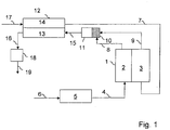
- FIG. 1 A fuel cell system according to the invention is shown.
- An oxide-ceramic fuel cell stack (1) is supplied to the anode (2) with a hydrogen-rich gas, also called reformate, via the fuel gas line (4).
- the hydrogen-rich gas is made from a hydrocarbon-rich fuel, e.g. Natural gas, which is supplied via the fuel line, (6) is generated in the reformer (5).
- Preheated air (7) is fed to the cathode (3). This is generated in the cathode air preheater (12), where the heat is transmitted to the air-side channels (14) via exhaust-side channels (13) of the cathode-air preheater (12).
- the anode off gas (8) a hydrogen-containing exhaust gas from the anode, still contains combustible components when it leaves the anode (2).
- the anode off gas (8) is mixed in the mixing chamber (10) as homogeneously as possible with the still oxygen-containing cathode exhaust air (9) and introduced into a reaction space (11), where the combustible components can react with the oxygen in a homogeneous reaction.
- This homogeneous reaction takes place at the temperature at which cathode exhaust air and anode off-gas leave the fuel cell. In the case of oxide ceramic fuel cells, this temperature level should be set at around 800 ° C to 850 ° C.
- the exhaust gas (15) formed then assumes a temperature level which is above the operating temperature of the fuel cell. This makes it suitable to preheat the cathode air sufficiently.
- the exhaust gas (16) cooled in the cathode air preheater (12) assumes a temperature between 300 ° C and 400 ° C and is fed to an exhaust gas catalytic converter (18), where the last combustible components are catalytically combusted.
- the exhaust gas (19) cleaned in this way can then be released into the environment, since all emission control targets are now safely met.
- the total oxidation catalyst (18) is preferably a noble metal catalyst, e.g. Platinum catalyst, platinum / palladium catalyst, platinum / palladium / rhodium catalyst, platinum / ruthenium catalyst, platinum / palladium / ruthenium catalyst or platinum / palladium / lanthanum catalyst
- a noble metal catalyst e.g. Platinum catalyst, platinum / palladium catalyst, platinum / palladium / rhodium catalyst, platinum / ruthenium catalyst, platinum / palladium / ruthenium catalyst or platinum / palladium / lanthanum catalyst
- the catalyst (18) can be heated electrically for preheating.
- the catalyst (18) is applied to an electrically conductive catalyst support, e.g. a ferritic steel.
- the special stainless steel 1.4760 can be used up to 900 ° C and is characterized by particularly good heat and electrical conductivity. It is therefore proposed here to apply the afterburner catalyst to such a material.
- a hexaaluminate which is applied by means of a sol-gel process, can serve as the adhesion-promoting layer between the catalyst and the metallic support.
- an electrical current is applied to the catalyst carrier.
- the Joule heat released in this way heats the catalyst carrier and thus also the catalyst.
- the advantage of this arrangement is that the catalyst is brought evenly up to operating temperature by this new type of preheating. This favors the catalytic reactions on the surface of the catalyst. Even during operation, the active component can be safely heated electrically via the catalyst carrier if, for example, the catalyst cools down in the part-load range and the catalytic reaction threatens to come to a standstill.
Landscapes
- Chemical & Material Sciences (AREA)
- Engineering & Computer Science (AREA)
- Chemical Kinetics & Catalysis (AREA)
- Electrochemistry (AREA)
- Life Sciences & Earth Sciences (AREA)
- Manufacturing & Machinery (AREA)
- Sustainable Development (AREA)
- Sustainable Energy (AREA)
- General Chemical & Material Sciences (AREA)
- Organic Chemistry (AREA)
- Materials Engineering (AREA)
- Combustion & Propulsion (AREA)
- Fuel Cell (AREA)
Description
- Die Erfindung betrifft ein Brennstoffzellensystem mit gestuftem Nachbrenner mit Niedertemperatur-Abgaskatalyse.
- In Kraft-Wärme-Koppelungsanlagen (KWK) wird die anfallende Abwärme bei der Stromerzeugung noch genutzt, um andere Verbraucher mit thermischer Energie zu versorgen. Im Falle von Mikro-KWK-Anlagen soll oftmals die Abwärme genutzt werden, um kleinere Gebäude wie Einfamilienhäuser mit Wärme zu versorgen.
- Als Stromerzeuger für Mikro-KWK-Anlagen kommen verschiedene Energiewandler in Betracht, die chemische Energie in Form eines Brennstoffs in Strom und Wärme umwandeln können. Erdgasbasierte Brennstoffzellen-Heizgeräte werden für den Einsatz in der Hausenergieversorgung als Mikro-KWK-Anlage derzeit intensiv diskutiert, erforscht und entwickelt. Ein dort eingesetztes Brennstoffzellen-System besteht aus einer Brennstoffzelle bzw. einem Brennstoffzellen-Stapel und gegebenenfalls Zusatzaggregaten wie einem Reformer und einem Nachbrenner.
- Technische Brennstoffzellen benötigen in der Regel Wasserstoff als Brennstoff. Eine Wasserstoffinfrastruktur für die Versorgung stationärer Brennstoffzellensysteme, beispielsweise in Gebäuden, steht auch mittelfristig nicht zur Verfügung. Dieser Mangel wird dadurch beseitigt, dass stationäre Brennstoffzellensysteme fossile Brennstoffe nutzen, die in Gebäuden verfügbar sind. Solche Brennstoffe sind beispielsweise Erdgas, Flüssiggas (LPG), Heizöl sowie leichte und schwere Gasöle und Kohle. Des Weiteren können auch biogene Brennstoffe, wie Holz, Holzgas, Biogas oder "Bioerdgas" in solchen Systemen zum Einsatz kommen.
- Bei der Verwendung der o.g. Brennstoffe ist der Brennstoffzelle eine Brenngaserzeugung vorgeschaltet, die das benötigte wasserstoffreiche Brenngas aus dem Brennstoff mit Luft und/oder Wasser und/oder Kohlendioxid erzeugt. Typische Brenngaserzeugungsverfahren für stationäre Brennstoffzellensysteme in der Gebäudeversorgung sind Dampfreformierung (SR), Autotherme Dampfreformierung (ATR), Thermische oder katalytische partielle Oxidation (POX), Reformierung mit Kohlendioxid, Wasserdampfvergasung und Vergasung mit (Luft-) Sauerstoff. Die Reformierungsverfahren Autotherme Dampfreformierung (ATR) und die katalytische sowie thermische partielle Oxidation (POX) erfordern keine zusätzliche Wärmequelle.
- Im Falle der oxidkeramischen Brennstoffzelle (SOFC) stellt sich die Brenngaserzeugung besonders einfach dar, weil in der Brenngaserzeugungsstufe gebildetes Kohlenmonoxid weder konvertiert noch abgereinigt werden muss. Kohlenmonoxid stellt für SOFC Brennstoffzellen indirekt über den Reaktionsmechanismus
(1) H2 + ½ O2 ⇒ H2O (elektrochemische Umsetzung)
(2) CO + H2O ⇒ CO2 + H2 (Wassergas-Shift)
einen Brennstoff für diesen Brennstoffzellentyp dar. In der Brennstoffzelle wird nicht jeglicher Brennstoff umgesetzt, um die minimale erforderliche Klemmspannung aufrecht zu erhalten; so dass das Anodenabgas noch brennbare Bestandteile enthält. - Alle technischen Brennstoffzellen benötigten Wasserstoff als Brennstoff. Die verschiedenen Brennstoffzellentypen unterscheiden sich u.a. auch in ihren Anforderungen an die Wasser-stoffqualität und Reinheit. Allen Brennstoffzellen ist aber gemeinsam, dass diese mit einem Überschuss an Wasserstoff betrieben werden muss, um ein Absinken der Klemmspannung zu verhindern. Dies bedeutet aber, dass am Anodenausgang der Brennstoffzelle ein sogenanntes Anodenoffgas anliegt, welches noch Wasserstoff und ggf. noch andere brennbare Anteile enthält. Aus Effizienzgründen und Immissionsschutzgründen müssen diese brennbaren Anteile dem Anodenoffgas entzogen werden. Dies ist Aufgabe des Nachbrenners in Brennstoffzellensystemen.
- Ebenfalls aus Effizienzgründen ist man bemüht, den Wasserstoffüberschuss an der Anode so gering, wie möglich zu halten. Dies führt dazu, dass ein so genanntes Schwachgas nachverbrannt werden muss, welches nur geringe Volumenanteile an brennbaren Anteilen enthält. In manchen Anwendungen kann es zu dem vorteilhaft sein, das Anodenoffgas mit der Kathodenabluft gemeinsam nachzuverbrennen. Genau wie auf der Anode muss auch ein Sauerstoffüberschuss auf der Kathodenseite eingestellt werden, um den Sauerstoffpartialdruck aufrecht zu erhalten, um Absinken der Klemmspannung zu verhindern. Dies bedeutet, dass die Kathodenabluft noch genügend Sauerstoff mitführt, um das Anodenoffgas vollständig zu oxidieren.
- Auch wenn die Kathodenabluft nicht als Oxidator für die Nachverbrennung genutzt wird, sondern Luftsauerstoff als Verbrennungsluft genutzt wird, kommt es dennoch zu einer weiteren Verdünnung des Anodenoffgases durch den Stickstoffanteil der Luft.
- Solche Schwachgase können oftmals nicht mehr stabil homogen verbrannt werden, da deren Aktivität für eine homogene Verbrennung nicht mehr ausreicht. Um dennoch eine stabile und sichere Nachverbrennung zu gewährleisten, werden drei verschiedene Konzepte angewendet, die auch mit einander kombiniert werden können:
- * Stützfeuerung: Dem Schwachgas werden weitere brennbare Anteile hinzugefügt, um die Aktivität zu steigern. In diesem Fall wird quasi kein Schwachgas mehr verbrannt.
- * Senkung der Aktivierungsenergie: Durch den Einsatz von Katalysatoren kann die Aktivierungsenergie für die Nachverbrennung abgesenkt werden.
- * Vorwärmung: Die Edukte Anodenoffgas und Verbrennungsluft werden vorgewärmt, um die Nachverbrennung stabiler zu gestalten. Oftmals reicht diese Maßnahme schon aus, um ein Schwachgas zu verbrennen.
- Aufgabe des katalytischen Nachbrenner (ATO) in solchen Systemen ist es, diese brennbaren Bestandteile, die die Anode verlassen (Anodetailgas) mit einem Oxidator, z.B. Sauerstoff, Luftsauerstoff oder Kathodenabluft vollständig umzusetzen. Weitere Aufgabe des Nachbrenners ist es Prozesswärme für das System oder Nutzwärme, z.B. für die Gebäudeversorgung bereitzustellen.
- Aufgabe des Kathodenluftvorwärmers (C-APH) in einem SOFC-System ist es, Umgebungsluft auf eine definierte Temperatur vorzuwärmen, bevor diese der Kathode des SOFC Brennstoffzellen-Stapels zugeführt wird.
- Derzeit wird das heiße Abgas des Nachbrenners einem Gas-Gas Wärmeübertrager (Kathodenluftvorwärmer) zugeführt, wo die heißen Abgase des Nachbrenners abgekühlt werden und die angesaugte Umgebungsluft vorgewärmt wird, um dann dem SOFC Stack zugeführt zu werden.
- Nachteile dieser Anordnung sind, dass sowohl der Nachbrenner als auch der Kathodenluftvorwärmer abgasseitig Druckverluste verursachen, welche den elektrischen Wirkungsgrad von SOFC Brennstoffzellen negativ beeinflussen durch einen erhöhten Bedarf an Hilfsenergie für die erforderliche Gebläseleistung. Sowohl Nachbrenner als auch Kathodenluftvorwärmer verursachen Wärmeverluste, die den thermischen und somit auch den Gesamtwirkungsgrad von SOFC-Brennstoffzellensystemen negativ beeinflussen. Ebenfalls beanspruchen sowohl Nachbrenner als auch Kathodenluftvorwärmer für sich Bauraum und behindern so einen kompakten Systemaufbau. Darüber hinaus wird der Katalysator des katalytischen Nachbrenners mit 800 bis 900°C betrieben. Dadurch kommt es zur Kontaktsinterung kommerzieller Washcoatings, die die spezifische Oberfläche des Katalysator drastisch herab setzen. Diese Herabsetzung geht mit einem Verlust der Katalysatoraktivität einher.
- Bei Brennstoffzellen-Heizgeräten werden derzeit verschiedene Methoden verwendet, um das noch wasserstoffhaltige und brennbare Anodenoffgas oder Anodentailgas nachzuverbrennen, die nachstehend kurz erläutert werden sollen.
- * Das Anodenoffgas wird im Reformerbrenner eines Dampfreformers mitverbrannt. In dieser Anwendung kommt das Konzept der Stützfeuerung zum Tragen.
- * Offene Nachverbrennung: Bei der offenen Nachverbrennung werden Anodenoffgas und Kathodenabluft direkt hinter dem Brennstoffzellenstapel gemischt und in einer homogenen Reaktion werden die brennbaren Anteile oxidiert
- * Katalytischer Nachbrenner: Das Anodenoffgas wird mit der Kathodenabluft oder Luftsauerstoff gemischt und über einen Katalysator geleitet, wo die brennbaren Anteile oxidiert werden.
- * Kombination katalytische Nachverbrennung und homogene Reaktion: Anodenoffgas und Kathodenabluft eines SOFC-Systems werden in einer Mischkammer stromabwärts der Brennstoffzelle gemischt und einem Reaktionsraum zugeführt, wo eine homogene Reaktion stattfindet und ein Teil des Anodenoffgases oxidiert wird. Die Mischung wird dann über einen Katalysator geleitet, wo der Rest der brennbaren Bestandteile oxidiert wird.
-
DE 10 2008 009 063 A1 beschreibt eine Brennstoffzellenanlage, bei der die Abgase der Brennstoffzelle verbrannt werden und anschließend die Abgase abgekühlt werden, wobei die dabei gewonnen Wärme vorzugsweise der Brennnstoffzellenanlage wieder zugeführt wird. AusUS 2003/0157380 A1 ist eine PEM-Brennstoffzellenanlage mit einen katalytischen Nachbrenner Brenner bekannt, bei der ein wassergekühlter Wärmetauscher dem Nachbrenner vorgeschaltet ist, um eine Überhitzung des Katalysators zu verhindern.EP 2 284 938 A1 beschreibt einen Nachbrenner für eine Brennstoffzellenanlage, bei welcher dem katalytischen Brenner neben den Brennstoffzellenabgasen weitere Frischluft zugeführt wird, um die Reaktionstemperatur zu senken. Der zusätzliche Gasstrom erhöht den Druckverlust der Anlage. - Es ist daher Aufgabe der Erfindung, eine Anordnung zu schaffen, bei der die Standzeit des Katalysators eines Nachbrenners in einem SOFC-Brennstoffzellensystem erhöht wird und sein Druckverlust reduziert wird.
- Diese Aufgabe wird erfindungsgemäß durch ein Brennstoffzellensystem gemäß dem unabhängigen Anspruch gelöst.
- Der erfindungsgemäße Nachbrenner soll eine zuverlässige Reduktion der Emissionen unter die geforderten Grenzwerte für Brennstoffzellensysteme ermöglichen. Dazu wird ein zweistufiger Nachbrenner vorgeschlagen. In der ersten Stufe soll eine homogene Oxidation des Anodenoffgases mit der sauerstoffhaltigen Kathodenabluft bei einer Temperatur ermöglicht werden, die der Temperatur des oxidkeramischen Brennstoffzellenstapels ähnlich ist und bei 800°C bis 850°C liegt. In einer zweiten katalytischen Stufe wird ein Katalysator eingesetzt, welcher bei einem Temperaturniveau bei ca. 350°C arbeitet, wird die Mischung aus sauerstoffhaltiger Kathodenabluft und Anodenoffgas katalytisch nachverbrannt.
- Der Vorteil ist, dass die Druckverluste im Abgassystem reduziert werden und dass die Katalysator-Standzeit durch Senkung der Temperaturbelastung erhöht wird. Gleizeitig können die Kosten des Katalysators reduziert werden und auf Katalysatortechnologie von kleinen Verbrennungsmotoren zurückgegriffen werden.
- Erfindungsgemäß ist dem Kathodenluftvorwärmer eine Mischkammer für Anodenoffgas und Kathodenabluft und ein dahinter angeordnete Reaktionsraum angeordnet.
- Optional ist der als Wärmetauscher wirkende Kathodenvorluftwärmer so gestaltet, dass die Abgastemperatur unter 400 °C, bevorzugt 300 bis 400 °C gesenkt wird. Dadurch wird die geringe Materialbelastung des Katalysators bewirkt.
- Ebenfalls optional ist in Anbetracht der niedrigen Abgastemperatur des Katalysators ein Edelmetallkatalysator, vorzugsweise ein Platin-Katalysator, Platin/Palladium-Katalysator, Platin/Palladium/Rhodium-Katalysator, Platin/Ruthenium-Katalysator, Platin/Palladium/Ruthenium-Katalysator oder ein Platin/Palladium/Lanthan-Katalysator.
- Erfindungsgemäß ist der Katalysator für die Startphase beheizbar. Dies wird ermöglicht durch einen metallischen Katalysatorträger, auf den das Katalysatormaterial aufgebracht ist, welcher zum Beispiel als Widerstandsheizung beheizt wird.
- Material des Katalysatorträgers ist bevorzugt ferritischer Stahl, besonders bevorzugt Sonderedelstahl 1.4760, welcher gut Strom und Wärme leitet.
- Als Haftvermittler zwischen Katalysatorträger und Katalysatormaterial kommt Hexaaluminat zum Einsatz, das bevorzugt in einem Sol-Gel-Verfahren aufgebracht wird.
- Die Erfindung wird nun anhand der Figur detailliert erläutert.
- Es stellt dar:
- Figur 1:
- Ein erfindungsgemäßes Brennstoffzellensystem.
- In
Figur 1 ist ein erfindungsgemäßes Brennstoffzellensystem dargestellt. - Einem oxidkeramischen Brennstoffzellenstapel (1) wird der Anode (2) ein wasserstoffreiches Gas, auch Reformat genannt, über die Brenngasleitung (4) zugeführt. Das wasserstoffreiche Gas wird aus einem kohlenwasserstoffreichen Brennstoff, z.B. Erdgas, welches über die Brennstoffleitung zugeführt wird, (6) in dem Reformer (5) erzeugt.
- Der Kathode (3) wird vorgewärmte Luft (7) zugeführt. Diese wird in dem Kathodenluftvorwärmer (12) erzeugt, wo die Wärme über abgasseitige Kanäle (13) des Kathodenluftvorwärmers (12) auf die luftseitigen Kanäle (14) übertragen wird.
- Das Anodenoffgas (8), ein wasserstoffhaltiges Abgas der Anode enthält noch brennbare Bestandteile, wenn es die Anode (2) verlässt. Das Anodenoffgas (8) wird in der Mischkammer (10) möglichst homogen mit der noch sauerstoffhaltigen Kathodenabluft (9) gemischt und in einem Reaktionsraum (11) eingeleitet, wo die brennbaren Bestandteile mit dem Sauerstoff in einer homogenen Reaktion miteinander reagieren können. Diese homogene Reaktion läuft bei der Temperatur ab, mit der Kathodenabluft und Anodenoffgas die Brennstoffzelle verlassen. Im Falle von oxidkeramischen Brennstoffzellen ist dieses Temperaturniveau bei ca. 800°C bis 850°C anzusetzen.
- Das gebildete Abgas (15) nimmt daraufhin ein Temperaturniveau an, welches oberhalb der Betriebstemperatur der Brennstoffzelle liegt. Dadurch ist es geeignet, die Kathodenluft ausreichend vorzuwärmen. Das im Kathodenluftvorwärmer (12) abgekühlte Abgas (16) nimmt eine Temperatur zwischen 300°C und 400°C an und wird einem Abgaskatalysator (18) zugeführt, wo letzte brennbare Bestandteile katalytisch nachverbrannt werden. Das so gereinigte Abgas (19) kann dann in die Umgebung abgegeben werden, da so jetzt alle Immissionsschutzziele sicher eingehalten werden.
- Der Katalysator (18) für die Totaloxidation ist vorzugsweise ein Edelmetallkatalysator, wie z.B. Platin-Katalysator, Platin/Palladium-Katalysator, Platin/Palladium/Rhodium-Katalysator, Platin/Ruthenium-Katalysator, Platin/Palladium/Ruthenium-Katalysator oder Platin/Palladium/Lanthan-Katalysator
- Dadurch dass die katalytische Abgasreinigung jetzt bei 300 bis 400°C arbeitet, statt wie bisher bei 800 bis 900°C, wird die Kontaktsinterung des Washcoats weitgehend vermieden und die Standzeit signifikant erhöht. Des Weiteren sinkt der Druckverlust über den Katalysator ab, da sich der Volumenstrom durch die Temperaturabsenkung entsprechend dem Boyle Mariott'sches Gesetz verringert.
- Zur Vorheizung ist der Katalysator (18) elektrisch beheizbar. Der Katalysator (18) wird auf einen elektrisch leitenden Katalysatorträger aufgebracht, z.B. ein ferritischer Stahl.
- Der Sonderedelstahl 1.4760 kann bis 900°C eingesetzt werden und zeichnet sich dabei durch besonders gute Wärme- und elektrische Leitfähigkeit aus. Daher wird hier vorgeschlagen, den Nachbrennerkatalysator auf ein solches Material aufzubringen. Als haftvermittelnde Schicht zwischen Katalysator und metallischen Träger kann ein Hexaaluminat dienen, welches mittels eines Sol-Gel-Verfahrens aufgebracht wird. Zur Erwärmung des Katalysators auf Betriebstemperatur wird ein elektrischer Strom an den Katalysatorträger angelegt. Durch so freiwerdende Joul'sche Wärme erwärmt sich der Katalysatorträger und somit auch der Katalysator. Vorteil dieser Anordnung ist dass der Katalysator durch diese neuartige Art der Vorwärmung gleichmäßig auf Betriebstemperatur gebracht wird. Dies begünstigt die katalytischen Reaktionen auf der Oberfläche des Katalysators. Auch während des Betriebes kann die aktive Komponente elektrisch gefahrlos über den Katalysatorträger weiter erwärmt werden, wenn beispielsweise im Teillastbereich der Katalysator auszukühlen und die katalytische Reaktion zu erliegen zu kommen droht.
-
- 1
- Brennstoffzellenstapel
- 2
- Anode
- 3
- Kathode
- 4
- Brenngasleitung
- 5
- Reformer
- 6
- Brennstoffleitung
- 7
- Vorgewärmte Kathodenluft
- 8
- Anodenoffgas
- 9
- Kathodenabluft
- 10
- Mischkammer
- 11
- Reaktionsraum
- 12
- Kathodenluftvorwärmer
- 13
- Abgasseitige Kanäle des Kathodenluftvorwärmers
- 14
- Luftseitige Kanäle des Kathodenluftvorwärmers
- 15
- Abgas
- 16
- Abgekühltes Abgas
- 17
- Frischluft
- 18
- Abgaskatalysator
- 19
- Gereinigtes Abgas
Claims (3)
- SOFC-Brennstoffzellensystem, insbesondere für den Einsatz in einer Kraft-Wärme-Kopplungsanlage, mit einem Reformer (5), einem Brennstoffzellenstapel (1), einem Abgaskatalysator (18) und einem Kathodenluftvorwärmer (12), wobei der Kathodenluftvorwärmer (12) in Strömungsrichtung des Abgases vor dem Abgaskatalysator (18) vorgesehen ist und wobei in Strömungsrichtung des Abgases vor dem Kathodenluftvorwärmer (12) eine Mischkammer für Anodenoffgas und Kathodenabluft und ein dahinter angeordneter Reaktionsraum (11) angeordnet ist, dadurch gekennzeichnet, dass das Katalysatormaterial des Katalysators (18) auf einem elektrisch leitenden Katalysatorträger aufgebracht ist, der elektrisch vorheizbar ist.
- Brennstoffzellensystem nach Anspruch 1, dadurch gekennzeichnet, dass der Katalysatorträger aus einem ferritischen Stahl, bevorzugt aus Sonderedelstahl 1.4760 ist.
- Brennstoffzellensystem nach Anspruch 1 oder 2, dadurch gekennzeichnet, dass als haftvermittelnde Schicht zwischen Katalysatormaterial und Katalysatorträger ein Hexaaluminat dient, welches bevorzugt mittels eines Sol-Gel-Verfahrens aufgebracht ist.
Applications Claiming Priority (1)
| Application Number | Priority Date | Filing Date | Title |
|---|---|---|---|
| DE102011011608 | 2011-02-17 |
Publications (3)
| Publication Number | Publication Date |
|---|---|
| EP2490289A1 EP2490289A1 (de) | 2012-08-22 |
| EP2490289B1 EP2490289B1 (de) | 2017-04-05 |
| EP2490289B2 true EP2490289B2 (de) | 2020-03-04 |
Family
ID=45655017
Family Applications (1)
| Application Number | Title | Priority Date | Filing Date |
|---|---|---|---|
| EP12000970.9A Not-in-force EP2490289B2 (de) | 2011-02-17 | 2012-02-15 | Brennstoffzellensystem |
Country Status (1)
| Country | Link |
|---|---|
| EP (1) | EP2490289B2 (de) |
Families Citing this family (2)
| Publication number | Priority date | Publication date | Assignee | Title |
|---|---|---|---|---|
| DE102016214907A1 (de) * | 2016-08-10 | 2018-02-15 | Vaillant Gmbh | SOFC-Brennstoffzellen-Stack |
| WO2019178627A1 (de) * | 2018-03-19 | 2019-09-26 | Avl List Gmbh | Brennstoffzellensystem und verfahren zum aufheizen eines brennstoffzellensystem |
Citations (6)
| Publication number | Priority date | Publication date | Assignee | Title |
|---|---|---|---|---|
| EP1497878A1 (de) † | 2002-04-23 | 2005-01-19 | Ceramic Fuel Cells Limited | Verfahren zum betrieb einer brennstoffzelle |
| EP1657771A1 (de) † | 2004-11-11 | 2006-05-17 | Bayerische Motorenwerke Aktiengesellschaft | In einem Kraftfahrzeug mit Verbrennungsmotor als Stromerzeuger eingesetztes Brennstoffzellensystem |
| WO2007014127A2 (en) † | 2005-07-25 | 2007-02-01 | Ion America Corporation | Fuel cell system with partial recycling of anode exhaust |
| WO2007014128A2 (en) † | 2005-07-25 | 2007-02-01 | Ion America Corporation | Fuel cell system with electrochemical anode exhaust recycling |
| WO2007087240A2 (en) † | 2006-01-23 | 2007-08-02 | Bloom Energy Corporation | Modular fuel cell system |
| EP2360767A1 (de) † | 2010-02-12 | 2011-08-24 | Hexis AG | Brennstoffzellensystem |
Family Cites Families (11)
| Publication number | Priority date | Publication date | Assignee | Title |
|---|---|---|---|---|
| US5541014A (en) | 1995-10-23 | 1996-07-30 | The United States Of America As Represented By The United States Department Of Energy | Indirect-fired gas turbine dual fuel cell power cycle |
| US6958195B2 (en) | 2002-02-19 | 2005-10-25 | Utc Fuel Cells, Llc | Steam generator for a PEM fuel cell power plant |
| DE10318495A1 (de) | 2003-04-24 | 2004-11-11 | Bayerische Motoren Werke Ag | Energieumwandlungsvorrichtung sowie Reformereinrichtung und Brennstoffzelleneinrichtung hierfür |
| US7169495B2 (en) | 2003-05-06 | 2007-01-30 | Versa Power Systems, Ltd. | Thermally integrated SOFC system |
| US20080187794A1 (en) | 2007-02-07 | 2008-08-07 | Bloom Energy Corporation | Venturi catalytic reactor inlet fuel mixer |
| DE102007018264A1 (de) | 2007-04-11 | 2008-10-16 | Ebz Entwicklungs- Und Vertriebsgesellschaft Brennstoffzelle Mbh | Hochtemperaturbrennstoffzellensystem |
| WO2009061299A1 (en) | 2007-11-07 | 2009-05-14 | Utc Power Corporation | Catalytic burning of fuel cell anode exhaust upstream of homogeneous burning of startup reformate |
| US8197976B2 (en) | 2008-01-04 | 2012-06-12 | Protonex Technology Corporation | Solid oxide fuel cell systems with hot zones and two-stage tail gas combustors |
| DE102008009063A1 (de) | 2008-02-13 | 2009-08-20 | J. Eberspächer GmbH & Co. KG | Brennstoffzellensystem |
| AT508488A1 (de) | 2009-07-13 | 2011-01-15 | Vaillant Group Austria Gmbh | Nachbrenner für erdgasbasierte brennstoffzellenheizgeräte |
| DE102009060679B4 (de) * | 2009-12-28 | 2026-01-15 | Eberspächer Climate Control Systems GmbH & Co. KG | Betriebsverfahren für ein Brennstoffzellensystem |
-
2012
- 2012-02-15 EP EP12000970.9A patent/EP2490289B2/de not_active Not-in-force
Patent Citations (6)
| Publication number | Priority date | Publication date | Assignee | Title |
|---|---|---|---|---|
| EP1497878A1 (de) † | 2002-04-23 | 2005-01-19 | Ceramic Fuel Cells Limited | Verfahren zum betrieb einer brennstoffzelle |
| EP1657771A1 (de) † | 2004-11-11 | 2006-05-17 | Bayerische Motorenwerke Aktiengesellschaft | In einem Kraftfahrzeug mit Verbrennungsmotor als Stromerzeuger eingesetztes Brennstoffzellensystem |
| WO2007014127A2 (en) † | 2005-07-25 | 2007-02-01 | Ion America Corporation | Fuel cell system with partial recycling of anode exhaust |
| WO2007014128A2 (en) † | 2005-07-25 | 2007-02-01 | Ion America Corporation | Fuel cell system with electrochemical anode exhaust recycling |
| WO2007087240A2 (en) † | 2006-01-23 | 2007-08-02 | Bloom Energy Corporation | Modular fuel cell system |
| EP2360767A1 (de) † | 2010-02-12 | 2011-08-24 | Hexis AG | Brennstoffzellensystem |
Also Published As
| Publication number | Publication date |
|---|---|
| EP2490289B1 (de) | 2017-04-05 |
| EP2490289A1 (de) | 2012-08-22 |
Similar Documents
| Publication | Publication Date | Title |
|---|---|---|
| CA2251627C (en) | Thermally enhanced compact reformer | |
| EP1228547B9 (de) | Brennstoffzellensystem | |
| US7160342B2 (en) | Fuel reformer system | |
| US9496567B2 (en) | Method and arrangement for utilizing recirculation for high temperature fuel cell system | |
| KR101165745B1 (ko) | 촉매보조 연소기를 구비하는 고온 발전용 연료전지 시스템 | |
| CN108023103B (zh) | 使用级联燃料电池的发电系统及其相关联方法 | |
| EP2284938B1 (de) | Nachbrenner für erdgasbasierte Brennstoffzellenheizgeräte | |
| CN113471492A (zh) | 使用固废合成气的燃料电池发电系统及发电方法 | |
| JP2014502020A (ja) | 固体酸化物形燃料電池システム及び固体酸化物形燃料電池システム運用方法 | |
| EP2490289B2 (de) | Brennstoffzellensystem | |
| EP1986263B1 (de) | Brennstoffzellensystem und zugehöriges Startverfahren | |
| DE112021000277T5 (de) | Brennstoffzellen-Stromerzeugungssystem | |
| EP2963722A1 (de) | Stromerzeugungssystem und verfahren mit kaskadierten brennstoffzellen | |
| CN101095254A (zh) | 燃料电池设备内的预热装置 | |
| Cheekatamarla et al. | Advanced tubular solid oxide fuel cells with high efficiency for internal reforming of hydrocarbon fuels | |
| DE10104607A1 (de) | Gaserzeugungssystem für ein Brennstoffzellensystem und Verfahren zum Betrieb eines Gaserzeugungssystems | |
| WO2009103554A1 (de) | Hochtemperatur-brennstoffzellensystem und verfahren zum erzeugen von strom und wärme mit hilfe eines hochtemperatur-brennstoffzellensystems | |
| AT408041B (de) | Brennstoffzellenanordnung | |
| DE102007033151B4 (de) | Betriebsverfahren für ein Brennstoffzellensystem | |
| EA013775B1 (ru) | Система топливных элементов с риформером и пламенным нейтрализатором | |
| AT507853B1 (de) | Sofc-brennstoffzelle mit einem externen dampfreformer | |
| AU780375B2 (en) | Fuel cell system | |
| Crampsie | A leading light [power fuel cells] | |
| DE19821478A1 (de) | Festkörperelektrolyt-Reaktorsystem zur Bereitstellung von elektrischer Energie und Wärme | |
| JP2002216831A (ja) | 燃料電池発電装置 |
Legal Events
| Date | Code | Title | Description |
|---|---|---|---|
| PUAI | Public reference made under article 153(3) epc to a published international application that has entered the european phase |
Free format text: ORIGINAL CODE: 0009012 |
|
| AK | Designated contracting states |
Kind code of ref document: A1 Designated state(s): AL AT BE BG CH CY CZ DE DK EE ES FI FR GB GR HR HU IE IS IT LI LT LU LV MC MK MT NL NO PL PT RO RS SE SI SK SM TR |
|
| AX | Request for extension of the european patent |
Extension state: BA ME |
|
| 17P | Request for examination filed |
Effective date: 20130123 |
|
| 17Q | First examination report despatched |
Effective date: 20150512 |
|
| REG | Reference to a national code |
Ref country code: DE Ref legal event code: R079 Ref document number: 502012009940 Country of ref document: DE Free format text: PREVIOUS MAIN CLASS: H01M0008040000 Ipc: B01J0037020000 |
|
| GRAP | Despatch of communication of intention to grant a patent |
Free format text: ORIGINAL CODE: EPIDOSNIGR1 |
|
| RIC1 | Information provided on ipc code assigned before grant |
Ipc: B01D 53/86 20060101ALN20161003BHEP Ipc: H01M 8/06 20060101ALI20161003BHEP Ipc: H01M 8/0662 20160101ALI20161003BHEP Ipc: H01M 8/04014 20160101ALI20161003BHEP Ipc: B01J 23/40 20060101ALI20161003BHEP Ipc: B01J 37/02 20060101AFI20161003BHEP Ipc: H01M 8/04007 20160101ALI20161003BHEP Ipc: H01M 8/04701 20160101ALI20161003BHEP Ipc: H01M 8/124 20160101ALI20161003BHEP Ipc: H01M 8/0612 20160101ALI20161003BHEP Ipc: H01M 8/04 20060101ALI20161003BHEP |
|
| INTG | Intention to grant announced |
Effective date: 20161018 |
|
| STAA | Information on the status of an ep patent application or granted ep patent |
Free format text: STATUS: GRANT OF PATENT IS INTENDED |
|
| GRAS | Grant fee paid |
Free format text: ORIGINAL CODE: EPIDOSNIGR3 |
|
| GRAA | (expected) grant |
Free format text: ORIGINAL CODE: 0009210 |
|
| STAA | Information on the status of an ep patent application or granted ep patent |
Free format text: STATUS: THE PATENT HAS BEEN GRANTED |
|
| AK | Designated contracting states |
Kind code of ref document: B1 Designated state(s): AL AT BE BG CH CY CZ DE DK EE ES FI FR GB GR HR HU IE IS IT LI LT LU LV MC MK MT NL NO PL PT RO RS SE SI SK SM TR |
|
| REG | Reference to a national code |
Ref country code: GB Ref legal event code: FG4D Free format text: NOT ENGLISH |
|
| REG | Reference to a national code |
Ref country code: CH Ref legal event code: EP |
|
| REG | Reference to a national code |
Ref country code: AT Ref legal event code: REF Ref document number: 881282 Country of ref document: AT Kind code of ref document: T Effective date: 20170415 |
|
| REG | Reference to a national code |
Ref country code: IE Ref legal event code: FG4D Free format text: LANGUAGE OF EP DOCUMENT: GERMAN |
|
| REG | Reference to a national code |
Ref country code: DE Ref legal event code: R096 Ref document number: 502012009940 Country of ref document: DE |
|
| REG | Reference to a national code |
Ref country code: NL Ref legal event code: MP Effective date: 20170405 |
|
| REG | Reference to a national code |
Ref country code: LT Ref legal event code: MG4D |
|
| PG25 | Lapsed in a contracting state [announced via postgrant information from national office to epo] |
Ref country code: NL Free format text: LAPSE BECAUSE OF FAILURE TO SUBMIT A TRANSLATION OF THE DESCRIPTION OR TO PAY THE FEE WITHIN THE PRESCRIBED TIME-LIMIT Effective date: 20170405 |
|
| PG25 | Lapsed in a contracting state [announced via postgrant information from national office to epo] |
Ref country code: ES Free format text: LAPSE BECAUSE OF FAILURE TO SUBMIT A TRANSLATION OF THE DESCRIPTION OR TO PAY THE FEE WITHIN THE PRESCRIBED TIME-LIMIT Effective date: 20170405 Ref country code: HR Free format text: LAPSE BECAUSE OF FAILURE TO SUBMIT A TRANSLATION OF THE DESCRIPTION OR TO PAY THE FEE WITHIN THE PRESCRIBED TIME-LIMIT Effective date: 20170405 Ref country code: FI Free format text: LAPSE BECAUSE OF FAILURE TO SUBMIT A TRANSLATION OF THE DESCRIPTION OR TO PAY THE FEE WITHIN THE PRESCRIBED TIME-LIMIT Effective date: 20170405 Ref country code: LT Free format text: LAPSE BECAUSE OF FAILURE TO SUBMIT A TRANSLATION OF THE DESCRIPTION OR TO PAY THE FEE WITHIN THE PRESCRIBED TIME-LIMIT Effective date: 20170405 Ref country code: NO Free format text: LAPSE BECAUSE OF FAILURE TO SUBMIT A TRANSLATION OF THE DESCRIPTION OR TO PAY THE FEE WITHIN THE PRESCRIBED TIME-LIMIT Effective date: 20170705 Ref country code: GR Free format text: LAPSE BECAUSE OF FAILURE TO SUBMIT A TRANSLATION OF THE DESCRIPTION OR TO PAY THE FEE WITHIN THE PRESCRIBED TIME-LIMIT Effective date: 20170706 |
|
| PG25 | Lapsed in a contracting state [announced via postgrant information from national office to epo] |
Ref country code: SE Free format text: LAPSE BECAUSE OF FAILURE TO SUBMIT A TRANSLATION OF THE DESCRIPTION OR TO PAY THE FEE WITHIN THE PRESCRIBED TIME-LIMIT Effective date: 20170405 Ref country code: BG Free format text: LAPSE BECAUSE OF FAILURE TO SUBMIT A TRANSLATION OF THE DESCRIPTION OR TO PAY THE FEE WITHIN THE PRESCRIBED TIME-LIMIT Effective date: 20170705 Ref country code: PL Free format text: LAPSE BECAUSE OF FAILURE TO SUBMIT A TRANSLATION OF THE DESCRIPTION OR TO PAY THE FEE WITHIN THE PRESCRIBED TIME-LIMIT Effective date: 20170405 Ref country code: RS Free format text: LAPSE BECAUSE OF FAILURE TO SUBMIT A TRANSLATION OF THE DESCRIPTION OR TO PAY THE FEE WITHIN THE PRESCRIBED TIME-LIMIT Effective date: 20170405 Ref country code: IS Free format text: LAPSE BECAUSE OF FAILURE TO SUBMIT A TRANSLATION OF THE DESCRIPTION OR TO PAY THE FEE WITHIN THE PRESCRIBED TIME-LIMIT Effective date: 20170805 Ref country code: LV Free format text: LAPSE BECAUSE OF FAILURE TO SUBMIT A TRANSLATION OF THE DESCRIPTION OR TO PAY THE FEE WITHIN THE PRESCRIBED TIME-LIMIT Effective date: 20170405 |
|
| REG | Reference to a national code |
Ref country code: DE Ref legal event code: R026 Ref document number: 502012009940 Country of ref document: DE |
|
| PLBI | Opposition filed |
Free format text: ORIGINAL CODE: 0009260 |
|
| PLAX | Notice of opposition and request to file observation + time limit sent |
Free format text: ORIGINAL CODE: EPIDOSNOBS2 |
|
| 26 | Opposition filed |
Opponent name: HEXIS AG Effective date: 20171215 |
|
| PG25 | Lapsed in a contracting state [announced via postgrant information from national office to epo] |
Ref country code: RO Free format text: LAPSE BECAUSE OF FAILURE TO SUBMIT A TRANSLATION OF THE DESCRIPTION OR TO PAY THE FEE WITHIN THE PRESCRIBED TIME-LIMIT Effective date: 20170405 Ref country code: DK Free format text: LAPSE BECAUSE OF FAILURE TO SUBMIT A TRANSLATION OF THE DESCRIPTION OR TO PAY THE FEE WITHIN THE PRESCRIBED TIME-LIMIT Effective date: 20170405 Ref country code: EE Free format text: LAPSE BECAUSE OF FAILURE TO SUBMIT A TRANSLATION OF THE DESCRIPTION OR TO PAY THE FEE WITHIN THE PRESCRIBED TIME-LIMIT Effective date: 20170405 Ref country code: CZ Free format text: LAPSE BECAUSE OF FAILURE TO SUBMIT A TRANSLATION OF THE DESCRIPTION OR TO PAY THE FEE WITHIN THE PRESCRIBED TIME-LIMIT Effective date: 20170405 Ref country code: SK Free format text: LAPSE BECAUSE OF FAILURE TO SUBMIT A TRANSLATION OF THE DESCRIPTION OR TO PAY THE FEE WITHIN THE PRESCRIBED TIME-LIMIT Effective date: 20170405 |
|
| PG25 | Lapsed in a contracting state [announced via postgrant information from national office to epo] |
Ref country code: SM Free format text: LAPSE BECAUSE OF FAILURE TO SUBMIT A TRANSLATION OF THE DESCRIPTION OR TO PAY THE FEE WITHIN THE PRESCRIBED TIME-LIMIT Effective date: 20170405 |
|
| PG25 | Lapsed in a contracting state [announced via postgrant information from national office to epo] |
Ref country code: SI Free format text: LAPSE BECAUSE OF FAILURE TO SUBMIT A TRANSLATION OF THE DESCRIPTION OR TO PAY THE FEE WITHIN THE PRESCRIBED TIME-LIMIT Effective date: 20170405 |
|
| PLBP | Opposition withdrawn |
Free format text: ORIGINAL CODE: 0009264 |
|
| PLAY | Examination report in opposition despatched + time limit |
Free format text: ORIGINAL CODE: EPIDOSNORE2 |
|
| REG | Reference to a national code |
Ref country code: CH Ref legal event code: PL |
|
| PG25 | Lapsed in a contracting state [announced via postgrant information from national office to epo] |
Ref country code: MT Free format text: LAPSE BECAUSE OF FAILURE TO SUBMIT A TRANSLATION OF THE DESCRIPTION OR TO PAY THE FEE WITHIN THE PRESCRIBED TIME-LIMIT Effective date: 20170405 Ref country code: MC Free format text: LAPSE BECAUSE OF FAILURE TO SUBMIT A TRANSLATION OF THE DESCRIPTION OR TO PAY THE FEE WITHIN THE PRESCRIBED TIME-LIMIT Effective date: 20170405 |
|
| PLBC | Reply to examination report in opposition received |
Free format text: ORIGINAL CODE: EPIDOSNORE3 |
|
| REG | Reference to a national code |
Ref country code: IE Ref legal event code: MM4A |
|
| REG | Reference to a national code |
Ref country code: BE Ref legal event code: MM Effective date: 20180228 |
|
| PG25 | Lapsed in a contracting state [announced via postgrant information from national office to epo] |
Ref country code: LI Free format text: LAPSE BECAUSE OF NON-PAYMENT OF DUE FEES Effective date: 20180228 Ref country code: LU Free format text: LAPSE BECAUSE OF NON-PAYMENT OF DUE FEES Effective date: 20180215 Ref country code: CH Free format text: LAPSE BECAUSE OF NON-PAYMENT OF DUE FEES Effective date: 20180228 |
|
| REG | Reference to a national code |
Ref country code: FR Ref legal event code: ST Effective date: 20181031 |
|
| PG25 | Lapsed in a contracting state [announced via postgrant information from national office to epo] |
Ref country code: IE Free format text: LAPSE BECAUSE OF NON-PAYMENT OF DUE FEES Effective date: 20180215 |
|
| PG25 | Lapsed in a contracting state [announced via postgrant information from national office to epo] |
Ref country code: FR Free format text: LAPSE BECAUSE OF NON-PAYMENT OF DUE FEES Effective date: 20180228 Ref country code: BE Free format text: LAPSE BECAUSE OF NON-PAYMENT OF DUE FEES Effective date: 20180228 |
|
| PLAY | Examination report in opposition despatched + time limit |
Free format text: ORIGINAL CODE: EPIDOSNORE2 |
|
| REG | Reference to a national code |
Ref country code: AT Ref legal event code: MM01 Ref document number: 881282 Country of ref document: AT Kind code of ref document: T Effective date: 20180215 |
|
| PG25 | Lapsed in a contracting state [announced via postgrant information from national office to epo] |
Ref country code: AT Free format text: LAPSE BECAUSE OF NON-PAYMENT OF DUE FEES Effective date: 20180215 |
|
| PLAY | Examination report in opposition despatched + time limit |
Free format text: ORIGINAL CODE: EPIDOSNORE2 |
|
| PLBC | Reply to examination report in opposition received |
Free format text: ORIGINAL CODE: EPIDOSNORE3 |
|
| PUAH | Patent maintained in amended form |
Free format text: ORIGINAL CODE: 0009272 |
|
| STAA | Information on the status of an ep patent application or granted ep patent |
Free format text: STATUS: PATENT MAINTAINED AS AMENDED |
|
| 27A | Patent maintained in amended form |
Effective date: 20200304 |
|
| AK | Designated contracting states |
Kind code of ref document: B2 Designated state(s): AL AT BE BG CH CY CZ DE DK EE ES FI FR GB GR HR HU IE IS IT LI LT LU LV MC MK MT NL NO PL PT RO RS SE SI SK SM TR |
|
| REG | Reference to a national code |
Ref country code: DE Ref legal event code: R102 Ref document number: 502012009940 Country of ref document: DE |
|
| PG25 | Lapsed in a contracting state [announced via postgrant information from national office to epo] |
Ref country code: TR Free format text: LAPSE BECAUSE OF FAILURE TO SUBMIT A TRANSLATION OF THE DESCRIPTION OR TO PAY THE FEE WITHIN THE PRESCRIBED TIME-LIMIT Effective date: 20170405 |
|
| PG25 | Lapsed in a contracting state [announced via postgrant information from national office to epo] |
Ref country code: PT Free format text: LAPSE BECAUSE OF FAILURE TO SUBMIT A TRANSLATION OF THE DESCRIPTION OR TO PAY THE FEE WITHIN THE PRESCRIBED TIME-LIMIT Effective date: 20170405 Ref country code: HU Free format text: LAPSE BECAUSE OF FAILURE TO SUBMIT A TRANSLATION OF THE DESCRIPTION OR TO PAY THE FEE WITHIN THE PRESCRIBED TIME-LIMIT; INVALID AB INITIO Effective date: 20120215 |
|
| PG25 | Lapsed in a contracting state [announced via postgrant information from national office to epo] |
Ref country code: MK Free format text: LAPSE BECAUSE OF NON-PAYMENT OF DUE FEES Effective date: 20170405 Ref country code: CY Free format text: LAPSE BECAUSE OF FAILURE TO SUBMIT A TRANSLATION OF THE DESCRIPTION OR TO PAY THE FEE WITHIN THE PRESCRIBED TIME-LIMIT Effective date: 20170405 |
|
| PG25 | Lapsed in a contracting state [announced via postgrant information from national office to epo] |
Ref country code: AL Free format text: LAPSE BECAUSE OF FAILURE TO SUBMIT A TRANSLATION OF THE DESCRIPTION OR TO PAY THE FEE WITHIN THE PRESCRIBED TIME-LIMIT Effective date: 20170405 |
|
| PGFP | Annual fee paid to national office [announced via postgrant information from national office to epo] |
Ref country code: IT Payment date: 20210226 Year of fee payment: 10 |
|
| PGFP | Annual fee paid to national office [announced via postgrant information from national office to epo] |
Ref country code: DE Payment date: 20210202 Year of fee payment: 10 Ref country code: GB Payment date: 20210201 Year of fee payment: 10 |
|
| REG | Reference to a national code |
Ref country code: DE Ref legal event code: R119 Ref document number: 502012009940 Country of ref document: DE |
|
| GBPC | Gb: european patent ceased through non-payment of renewal fee |
Effective date: 20220215 |
|
| PG25 | Lapsed in a contracting state [announced via postgrant information from national office to epo] |
Ref country code: GB Free format text: LAPSE BECAUSE OF NON-PAYMENT OF DUE FEES Effective date: 20220215 Ref country code: DE Free format text: LAPSE BECAUSE OF NON-PAYMENT OF DUE FEES Effective date: 20220901 |
|
| PG25 | Lapsed in a contracting state [announced via postgrant information from national office to epo] |
Ref country code: IT Free format text: LAPSE BECAUSE OF NON-PAYMENT OF DUE FEES Effective date: 20220215 |