EP2490000B1 - Automatisiertes Einstecken eines Kontaktstabes in eine hüttentechnische Sonde - Google Patents
Automatisiertes Einstecken eines Kontaktstabes in eine hüttentechnische Sonde Download PDFInfo
- Publication number
- EP2490000B1 EP2490000B1 EP11154627.1A EP11154627A EP2490000B1 EP 2490000 B1 EP2490000 B1 EP 2490000B1 EP 11154627 A EP11154627 A EP 11154627A EP 2490000 B1 EP2490000 B1 EP 2490000B1
- Authority
- EP
- European Patent Office
- Prior art keywords
- probe
- contact rod
- longitudinal axis
- storage location
- predetermined
- Prior art date
- Legal status (The legal status is an assumption and is not a legal conclusion. Google has not performed a legal analysis and makes no representation as to the accuracy of the status listed.)
- Active
Links
Images




Classifications
-
- G—PHYSICS
- G01—MEASURING; TESTING
- G01K—MEASURING TEMPERATURE; MEASURING QUANTITY OF HEAT; THERMALLY-SENSITIVE ELEMENTS NOT OTHERWISE PROVIDED FOR
- G01K13/00—Thermometers specially adapted for specific purposes
- G01K13/12—Thermometers specially adapted for specific purposes combined with sampling devices for measuring temperatures of samples of materials
- G01K13/125—Thermometers specially adapted for specific purposes combined with sampling devices for measuring temperatures of samples of materials for siderurgical purposes
-
- G—PHYSICS
- G01—MEASURING; TESTING
- G01D—MEASURING NOT SPECIALLY ADAPTED FOR A SPECIFIC VARIABLE; ARRANGEMENTS FOR MEASURING TWO OR MORE VARIABLES NOT COVERED IN A SINGLE OTHER SUBCLASS; TARIFF METERING APPARATUS; MEASURING OR TESTING NOT OTHERWISE PROVIDED FOR
- G01D11/00—Component parts of measuring arrangements not specially adapted for a specific variable
- G01D11/30—Supports specially adapted for an instrument; Supports specially adapted for a set of instruments
-
- G—PHYSICS
- G01—MEASURING; TESTING
- G01N—INVESTIGATING OR ANALYSING MATERIALS BY DETERMINING THEIR CHEMICAL OR PHYSICAL PROPERTIES
- G01N1/00—Sampling; Preparing specimens for investigation
- G01N1/02—Devices for withdrawing samples
- G01N1/10—Devices for withdrawing samples in the liquid or fluent state
- G01N1/12—Dippers; Dredgers
- G01N1/125—Dippers; Dredgers adapted for sampling molten metals
-
- Y—GENERAL TAGGING OF NEW TECHNOLOGICAL DEVELOPMENTS; GENERAL TAGGING OF CROSS-SECTIONAL TECHNOLOGIES SPANNING OVER SEVERAL SECTIONS OF THE IPC; TECHNICAL SUBJECTS COVERED BY FORMER USPC CROSS-REFERENCE ART COLLECTIONS [XRACs] AND DIGESTS
- Y10—TECHNICAL SUBJECTS COVERED BY FORMER USPC
- Y10T—TECHNICAL SUBJECTS COVERED BY FORMER US CLASSIFICATION
- Y10T29/00—Metal working
- Y10T29/49—Method of mechanical manufacture
- Y10T29/49764—Method of mechanical manufacture with testing or indicating
- Y10T29/49771—Quantitative measuring or gauging
- Y10T29/49776—Pressure, force, or weight determining
-
- Y—GENERAL TAGGING OF NEW TECHNOLOGICAL DEVELOPMENTS; GENERAL TAGGING OF CROSS-SECTIONAL TECHNOLOGIES SPANNING OVER SEVERAL SECTIONS OF THE IPC; TECHNICAL SUBJECTS COVERED BY FORMER USPC CROSS-REFERENCE ART COLLECTIONS [XRACs] AND DIGESTS
- Y10—TECHNICAL SUBJECTS COVERED BY FORMER USPC
- Y10T—TECHNICAL SUBJECTS COVERED BY FORMER US CLASSIFICATION
- Y10T29/00—Metal working
- Y10T29/49—Method of mechanical manufacture
- Y10T29/49826—Assembling or joining
Definitions
- the present invention further relates to a holding frame having a plurality of such bearings.
- metallurgical probes which have a probe longitudinal axis and are open at one end face. At the other end they are closed. The probes are usually used only once and then disposed of.
- the probes are connected to a contact rod so that the contact rod is inserted into the probe (condition). Then, the contact rod including the plugged probe by means of a manipulator or robot or the like is immersed in the molten metal and thus fed the probe to its intended purpose. Thereafter, the contact rod including the attached probe is pulled out of the molten metal. Thereafter, the probe is removed from the contact rod.
- the contact rod is often plastically bent when the contact rod is immersed in the molten metal.
- the extent of plastic deflection can vary.
- the contact rod may have a diameter of about 16 mm
- the probe has an inner diameter of about 16.5 mm to 17.0 mm.
- the end of the contact rod to be inserted into the probe often vibrates and vibrates, for example due to vibrations and the more or less jerky movement of large masses. Even such vibrations and vibrations complicate the automated insertion of the end of the contact rod in the probe considerably due to the required positioning accuracy.
- the known centering device must be forcibly openable, since otherwise the contact rod could be pulled out of the probe again after insertion into the probe, but could not be removed together with the probe of the centering device.
- the known centering device must therefore comprise a corresponding actuator, corresponding moving parts, a power supply and a control device. It is therefore on the one hand relatively complex and expensive and on the other hand due to the harsh operating conditions in metallurgical plants relatively susceptible to interference.
- a method for inserting a contact rod in a metallurgical probe and a storage location for the metallurgical probe is known.
- the bearing point Before inserting the contact rod into the probe, the bearing point is equipped with the probe such that the open end side of the probe faces a plug-in direction.
- the bearing comprises an inlet centering device for the contact rod.
- the object of the present invention is to provide opportunities by means of which a simple way reliable automated insertion of the end of the contact rod into the probe is possible.
- the contact rod In the event that the contact rod would be unbent, the contact rod would have to be moved in the insertion direction to an ideal position so that the end of the contact rod is positioned at the predetermined contact rod position, as seen through insertion into the contact rod centering device transverse to the probe longitudinal axis. For example, it is possible for the contact rod to be moved beyond the ideal position in the insertion direction. Due to such "overshoot", the end of the contact rod, regardless of whether the contact rod is bent or not, always contacts the contact rod centering device, thereby assuming the defined position and suppressing vibrations and vibrations.
- an equivalent configuration is that during the insertion of the end of the contact rod in the Kunststoffstabzentrier adopted a force required to insert the end of the contact rod force is detected and the achievement of the predetermined contact rod position is detected by the force.
- the insertion of the end of the contact rod in the probe is particularly simple and reliable in that the contact rod when moving in the direction of the probe longitudinal axis initially only a piece is inserted into the probe, the contact rod is then moved against the insertion of the predetermined contact rod position out and the contact rod is then fully inserted into the probe.
- the plug-in is further facilitated if the probe is widened before loading the bearing at its open end.
- the corresponding widening may in particular be funnel-shaped.
- the holding and moving device may be formed as needed.
- it can be designed as a robot arm.
- the bearing point on its the Kunststoffstabzentrier adopted with respect to the probe opposite side has a stop for the probe, by means of which a displacement of the probe in the direction of the probe longitudinal axis is prevented.
- the object is further achieved by a holding frame having a plurality of such bearings.
- the bearings can be arranged in particular in a two-dimensional grid.
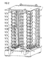
- FIG. 1 and 2 has a holding frame 1 a plurality of bearings 2.
- the bearings 2 are in accordance with FIG. 1 and 2 arranged in a two-dimensional grid.
- the bearings 2 could be arranged in a one-dimensional grid. Theoretically, even an irregular arrangement of the bearings 2 is possible. It is crucial that the bearings 2 are at defined locations.
- the bearings 2 are each designed to accommodate one (supplement: single) hutchnischen probe 3.
- Such probes 3 are well known to those skilled in the art. They serve, for example, the removal of samples in molten metals or the temperature measurement of such molten metal. As molten metals are in particular iron, steel, copper and aluminum in question. There are other metals possible.
- FIG. 3 shows a typical probe 3 in cross section.
- the probe 3 is tube-like. It has a probe longitudinal axis 4, along which it extends.
- a length 1 of the probe 3 is often in the range of 1 m to 2 m.
- An outer diameter D of the probe is often about 2.5 cm to 5 cm.
- the probe 3 is hollow inside. It has an inner diameter d, which is usually 12 mm to 20 mm, for example 16.5 mm to 17.0 mm.
- the probe 3 has two end faces 5, 5 '. On one end face 5 - hereinafter called open end 5 - the probe 3 is open. At the other end face 5 '- hereinafter closed end face 5' called - the probe 3 is closed.
- the probe 3 as shown by FIG. 3 widened at its open end 5.
- a corresponding expansion 6 ' may in particular be funnel-shaped.
- the timing at which the probe 3 is expanded may be determined as needed. For example, the expansion can already take place during the manufacture of the probe 3. Alternatively, it can be done later. It is crucial that the probe 3 is inserted into the probe 3 before inserting the probe 3 into one of the bearing points 2 of the holding frame 1, that is to say before the respective bearing point 2 is loaded with the respective probe 3.
- FIG. 4 schematically shows one of the bearings 2 of the support frame 1, wherein the bearing 2 shown is equipped with a probe 3.
- the corresponding bearing 2 has therefore already been fitted.
- the loading of the bearing 2 with the probe 3 was carried out such that the open end face 5 faces a predetermined insertion direction.
- FIG. 4 has the bearing 2 probe centering 6, by means of which the probe 3 in the bearing 2 transverse to Probe longitudinal axis 4 is held in a predetermined position.
- This position is called probe position below.
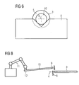
- the probe centering elements 6 may be formed as steel webs, which - see FIG. 5 - Have on their top a V-shaped (alternatively, for example, U-shaped or Y-shaped) recess 7.
- the probe centering elements 6 could also be designed, for example, as slots, in which the slot width corresponds to the outer diameter D of the probe 3.
- probe centering elements 6 there are two such probe centering elements 6.
- the number of probe centering elements 6 is arbitrary. Minimal, only a single probe centering 6 must be present. Alternatively, three, four, five, etc. probe centering elements 6 could also be present.
- the bearing 2 has according to FIG. 4 Furthermore, a Kunststoffstabzentrier issued 8.
- the Kunststoffstabzentrier issued 8 is formed such that in them - see FIG. 6 and 7 - One end 9 of a contact rod 10 is inserted.
- the insertion of the end 9 of the contact rod 10 in the Kunststoffstabzentrier Vietnamese 8 takes place in an insertion direction.
- the insertion direction - see the arrow in FIG. 8 - is how out of the FIGS. 6 to 8 can be seen, transverse to the longitudinal axis of the probe 4.
- the insertion is in accordance with FIG. 8 caused by a holding and moving device 11, which holds the contact rod 10 in a holding portion 12 of the contact rod 10.
- the holding and moving device 11 is according to FIG. 8 designed as a robot arm. This embodiment is possible and preferred, but not mandatory.
- a distance of the holding portion 12 of the contact rod 10 from the end 9 of the contact rod 10 is often 1 m or more.
- the insertion direction is from top to bottom. In principle, however, the direction can be arbitrary. It is crucial that the end 9 of the contact rod 10 is inserted so long in the insertion direction in the Kunststoffstabzentrier Anlagen 8 until the end 9 of the contact rod 10 due to insertion into the Kunststoffstabzentrier Anlagen 8 is positioned transversely to the probe longitudinal axis 4 at a predetermined contact rod position.
- the contact rod position is - see in particular the FIG. 6 and 7 - Selected such that the end 9 of the contact rod 10 of the open end face 5 (complement: exactly or sufficiently accurate) is opposite. This position of the end 9 of the contact rod 10 is shown schematically in FIG FIG. 9 shown.
- the contact rod 10 is therefore next - see FIG. 10 - Moved by means of the holding and moving device 11 in the direction of the probe longitudinal axis 4 and thereby inserted into the probe 3.
- the probe 3 is held during the insertion of the end 9 of the contact rod 10 by its own weight and frictional forces in the probe centering elements 6.
- the probe 3 may possibly be moved a small distance until the closed end 5 'of the probe 3 is pressed against the stop 13. Thereafter, however, a (further) displacement of the probe 3 in the direction of the probe longitudinal axis 4 by means of the stop 13 is prevented.
- the contact rod 10 when moving in the direction of the probe longitudinal axis 4 is initially only a piece inserted into the probe 3, for example, 10% to 25% of the full insertion length. This condition is in FIG. 10 shown. Then the contact rod 10 (and with it the probe 3) is moved out of the predetermined contact rod position counter to the insertion direction. This condition is in FIG. 11 shown schematically. Only in this state, the contact rod 10 is completely inserted into the probe 3. It is possible to also plug in the Contact rod 10 in the probe 3 step by step. Alternatively, in the second step, insertion can take place around the entire remaining insertion length.
- the Kunststofftrier worn 8 may be formed in various ways.
- the Kunststoffstabzentrier noticed 8 as shown in the FIG. 6 and 7 as a substantially V-shaped (alternatively, for example, U-shaped) channel is formed.
- alternative designs are possible, for example, as in FIG. 12 shown, Y-shaped.
- the contact rod 10 is plastically bent.
- the contact rod 10 no longer has its ideal shape, the in FIG. 13 is shown in solid lines, but it is bent. Possible bends are in FIG. 13 - greatly exaggerated - shown in dashed lines.
- a motor current or an engine torque of a drive of the holding and moving device 11 can be detected.
- the achievement of the predetermined contact rod position can be detected by the force.
- the end 9 of the contact rod 10 are first approached orthogonal to a first edge 14 of the Kunststoffstabzentrier adopted 8 to this edge 14.
- the reaching of the edge 14 can be detected, for example, by an increase in the required for moving the contact rod 10 electric current.
- the end 9 of the contact rod 10 can be further moved by methods along the edge 14 on a second edge 14 'of the Kunststoffstabzentrier adopted 8 until the End 9 of the contact rod 10 at the second edge 14 'of Kunststoffstabzentrier adopted 8 is present.
- the achievement of the second edge 14 ' can be detected by a corresponding increase in the motor current.
- the end 9 of the contact rod 10 can be successively moved up to the two edges 14, 14 'and each reaching the edge 14, 14' are detected, wherein during the two approaching the end 9 of the contact rod 10 from the other edge 14th ', 14 is kept at a distance. Thereby can be determined - in two dimensions - the extent to which the contact rod 10 is bent.
- a formed by the Kunststoffstabzentrier worn 8 guide funnel is - see FIG. 15 - relatively steep.
- an opening angle ⁇ of the guide funnel is in accordance with FIG. 15 maximum 90 °.
- the insertion corresponds approximately to the bisector. If the contact rod 10 were not bent, the position of the end 9 of the contact rod 10 by the position of the holding and moving device 11 - within narrow limits - would be uniquely determined. In particular, there is an ideal position in which the undeflected contact rod 10 is held such that the end 9 of the unbent contact rod 10 is positioned just in the contact rod position. This position of the end 9 of the contact rod 10 is in FIG. 15 dashed lines.
- the contact rod 10 is not only moved to the said ideal position, but beyond. If the contact rod 10 were unbent and the Whystabzentrier Too 8 were not present, would be the end 9 of the contact rod 10 at a position in FIG. 15 dash-dotted lines is shown. If the contact rod 10 is unbent and the Whystabzentrier Vietnamese 8 is present, the contact rod 10 is therefore positioned by the Whystabzentrier Vietnamese 8 in the desired contact rod position, wherein the contact rod 10 is elastically bent. So it works one Bending force F with which the end 9 of the contact rod 10 is held in the desired contact rod position.
- the present invention has many advantages.
- Maintenance work in relation to the support frame 1 or 2 bearings therefore completely eliminated. It is only necessary from time to time to stock the bearings 2 with new probes 3. This loading can be done quickly and easily, with this assembly process alternatively an automated or a manual approach can be done.
Landscapes
- Physics & Mathematics (AREA)
- General Physics & Mathematics (AREA)
- Life Sciences & Earth Sciences (AREA)
- Hydrology & Water Resources (AREA)
- Health & Medical Sciences (AREA)
- Chemical & Material Sciences (AREA)
- Analytical Chemistry (AREA)
- Biochemistry (AREA)
- General Health & Medical Sciences (AREA)
- Immunology (AREA)
- Pathology (AREA)
- A Measuring Device Byusing Mechanical Method (AREA)
- Measuring Leads Or Probes (AREA)
- Heat Treatment Of Articles (AREA)
Description
- Automatisiertes Einstecken eines Kontaktstabes in eine hüttentechnische Sonde
- Die vorliegende Erfindung betrifft ein Verfahren zum Einstecken eines mittels einer Halte- und Bewegungsvorrichtung in einem Haltebereich gehaltenen Kontaktstabes in eine eine Sondenlängsachse aufweisende, an einer Stirnseite offene hüttentechnische Sonde,
- wobei eine Lagerstelle für die Sonde mit der Sonde derart bestückt wird, dass deren offene Stirnseite einer vorbestimmten Einsteckrichtung zugewandt ist,
- wobei die Lagerstelle Sondenzentrierelemente aufweist, mittels derer die Sonde in der Lagerstelle quer zur Sondenlängsachse gesehen in einer vorbestimmten Sondenposition gehalten wird,
- wobei ein Ende des Kontaktstabes in eine Kontaktstabzentriereinrichtung eingeführt wird und dadurch derart positioniert wird, dass das Ende des Kontaktstabes der offenen Stirnseite gegenüber liegt,
- wobei sodann der Kontaktstab in Richtung der Sondenlängsachse bewegt und dadurch in die Sonde eingesteckt wird.
- Die vorliegende Erfindung betrifft weiterhin eine Lagerstelle für eine eine Sondenlängsachse aufweisende, an einer Stirnseite offene hüttentechnische Sonde,
- wobei die Lagerstelle Sondenzentrierelemente aufweist, mittels derer die Sonde in der Lagerstelle quer zur Sondenlängsachse gesehen in einer vorbestimmten Sondenposition gehalten wird,
- wobei die Lagerstelle eine Kontaktstabzentriereinrichtung aufweist, in die ein Ende eines mittels einer Halte- und Bewegungsvorrichtung in einem Haltebereich gehaltenen Kontaktstabes einführbar ist, so dass das Ende des Kontaktstabes aufgrund des Einführens in die Kontaktstabzentriereinrichtung quer zur Sondenlängsachse gesehen bei einer vorbestimmten Kontaktstabposition positioniert ist.
- Die vorliegende Erfindung betrifft weiterhin einen Halterahmen, der eine Vielzahl derartiger Lagerstellen aufweist.
- Bei der Herstellung von Eisen, Stahl und anderen Metallen werden Proben des flüssigen Metalls entnommen, erfolgt eine Temperaturerfassung usw.. Für derartige Aufgaben werden hüttentechnische Sonden verwendet, die eine Sondenlängsachse aufweisen und an einer Stirnseite offen sind. An der anderen Stirnseite sind sie geschlossen. Die Sonden werden in der Regel nur einmal verwendet und danach entsorgt.
- Im Stand der Technik werden die Sonden mit einem Kontaktstab verbunden, so dass der Kontaktstab in die Sonde eingesteckt ist (Zustand). Sodann wird der Kontaktstab einschließlich der aufgesteckten Sonde mittels eines Manipulators oder Roboters oder dergleichen in die Metallschmelze getaucht und so die Sonde ihrer Zweckbestimmung zugeführt. Danach wird der Kontaktstab einschließlich der aufgesteckten Sonde aus der Metallschmelze herausgezogen. Danach wird die Sonde vom Kontaktstab entfernt.
- Im Stand der Technik ist bekannt, dass ein Arbeiter die jeweils zu verwendende Sonde aus einem Vorratsbehälter entnimmt und manuell auf den Kontaktstab aufsteckt. Dies ist umständlich, mühsam und aufgrund der rauen Betriebsverhältnisse in hüttentechnischen Anlagen möglichst zu vermeiden. Es ist daher eine automatisierte Lösung anzustreben. Für die Realisierung einer automatisierten Lösung stellen sich jedoch im Wesentlichen zwei Probleme.
- Zum einen wird beim Eintauchen des Kontaktstabes in die Metallschmelze der Kontaktstab oftmals plastisch verbogen. Das Ausmaß der plastischen Verbiegung kann variieren. Aufgrund des Umstands, dass das in die Sonde einzusteckende Ende des Kontaktstabes jedoch sehr genau positioniert werden muss, sind auch geringfügige Verbiegungen bezüglich eines automatisierten Einsteckens des Endes des Kontaktstabes in die Sonde kritisch. Beispielsweise kann der Kontaktstab einen Durchmesser von ca. 16 mm aufweisen, die Sonde einen Innendurchmesser von ca. 16,5 mm bis 17,0 mm.
- Zum anderen schwingt und vibriert das in die Sonde einzusteckende Ende des Kontaktstabes oftmals, beispielsweise aufgrund von Erschütterungen und dem mehr oder minder ruckartigen Bewegen großer Massen. Auch derartige Schwingungen und Vibrationen erschweren aufgrund der erforderlichen Positioniergenauigkeit das automatisierte Einstecken des Endes des Kontaktstabes in die Sonde erheblich.
- Um dennoch eine automatisierte Lösung realisieren zu können, ist es im Stand der Technik bekannt, eine Zentriervorrichtung zu verwenden, die einen kontaktstabseitigen Trichterbereich und einen sondenseitigen Trichterbereich aufweist, die an ihren Engstellen ineinander übergehen. Durch Einführen des Endes des Kontaktstabes in den kontaktstabseitigen Trichterbereich und Einführen der Sonde in den sondenseitigen Trichterbereich werden das Ende des Kontaktstabes und die offene Stirnseite der Sonde relativ zueinander zentriert, so dass das Ende des Kontaktstabes in die Sonde eingesteckt werden kann.
- Die bekannte Zentriervorrichtung muss zwangsweise öffenbar sein, da anderenfalls der Kontaktstab nach dem Einstecken in die Sonde zwar wieder aus der Sonde herausgezogen werden könnte, aber nicht zusammen mit der Sonde der Zentriervorrichtung entnommen werden könnte. Die bekannte Zentriervorrichtung muss daher eine entsprechende Aktorik, entsprechende bewegte Teile, eine Energieversorgung und eine Steuereinrichtung umfassen. Sie ist daher zum einen relativ komplex und teuer und zum anderen aufgrund der rauen Betriebsverhältnisse in hüttentechnischen Anlagen relativ störanfällig.
- Aus der
DE 25 52 270 A1 ist ein Verfahren zum Einstecken eines Kontaktstabes in eine hüttenmännische Sonde und eine Lagerstelle für die hüttenmännische Sonde bekannt. Vor dem Einstecken des Kontaktstabs in die Sonde wird die Lagerstelle mit der Sonde derart bestückt, dass die offene Stirnseite der Sonde einer Einsteckrichtung zugewandt ist. Die Lagerstelle umfasst eine Einlaufzentriereinrichtung für den Kontaktstab. - Aus der Veröffentlichung "SIMETAL LiquiRob for EAF" der Siemens VAI Metals Technologies GmbH ist die Verwendung eines Roboters für die automatische Probennahme bekannt.
- Die Aufgabe der vorliegenden Erfindung besteht darin, Möglichkeiten zu schaffen, mittels derer auf einfache Weise ein zuverlässiges automatisiertes Einstecken des Endes des Kontaktstabes in die Sonde möglich ist.
- Die Aufgabe wird durch ein Verfahren mit den Merkmalen des Anspruchs 1 gelöst. Vorteilhafte Ausgestaltungen des erfindungsgemäßen Verfahrens sind Gegenstand der abhängigen Ansprüche 2 bis 7.
- Erfindungsgemäß ist vorgesehen, ein Verfahren zum Einstecken eines mittels einer Halte- und Bewegungsvorrichtung in einem Haltebereich gehaltenen Kontaktstabes in eine eine Sondenlängsachse aufweisende, an einer Stirnseite offene hüttentechnische Sonde zu schaffen,
- wobei eine Lagerstelle für die Sonde mit der Sonde derart bestückt wird, dass deren offene Stirnseite einer vorbestimmten Einsteckrichtung zugewandt ist,
- wobei die Lagerstelle Sondenzentrierelemente aufweist, mittels derer die Sonde in der Lagerstelle quer zur Sondenlängsachse gesehen in einer vorbestimmten Sondenposition gehalten wird,
- wobei ein Ende des Kontaktstabes in einer quer zur Sondenlängsachse verlaufenden Einführrichtung in eine Kontaktstabzentriereinrichtung einführt wird, bis das Ende des Kontaktstabes aufgrund des Einführens in die Kontaktstabzentriereinrichtung quer zur Sondenlängsachse gesehen bei einer vorbestimmten Kontaktstabposition positioniert ist, bei welcher das Ende des Kontaktstabes der offenen Stirnseite gegenüberliegt,
- wobei sodann der Kontaktstab in Richtung der Sondenlängsachse bewegt und dadurch in die Sonde eingesteckt wird.
- Durch diese Vorgehensweise wird erreicht, dass das Ende des Kontaktstabes zuverlässig in die Sonde eingesteckt werden kann, ohne eine komplexe angetriebene, gesteuerte usw. Zentriervorrichtung zu benötigen. Die Lagerstelle kann vielmehr rein starr mechanisch ausgebildet sein.
- In dem Fall, dass der Kontaktstab unverbogen wäre, müsste der Kontaktstab in der Einführrichtung bis zu einer Idealposition bewegt werden, damit das Ende des Kontaktstabes aufgrund des Einführens in die Kontaktstabzentriereinrichtung quer zur Sondenlängsachse gesehen bei der vorbestimmten Kontaktstabposition positioniert ist. Es ist beispielsweise möglich, dass der Kontaktstab in der Einführrichtung über die Idealposition hinaus bewegt wird. Aufgrund eines derartigen "Überschießens" bzw. "Überbiegens" liegt das Ende des Kontaktstabes unabhängig davon, ob der Kontaktstab verbogen ist oder nicht, stets an der Kontaktstabzentriereinrichtung an, wodurch er zum einen die definierte Position annimmt und zum anderen Vibrationen und Schwingungen unterdrückt werden.
- Alternativ besteht eine gleichwertige Ausgestaltung darin, dass während des Einführens des Endes des Kontaktstabes in die Kontaktstabzentriereinrichtung eine zum Einführen des Endes des Kontaktstabes erforderliche Kraft erfasst wird und anhand der Kraft das Erreichen der vorbestimmten Kontaktstabposition erkannt wird.
- Das Einstecken des Endes des Kontaktstabes in die Sonde ist besonders einfach und zuverlässig dadurch möglich, dass der Kontaktstab beim Bewegen in Richtung der Sondenlängsachse zunächst nur ein Stück in die Sonde eingesteckt wird, der Kontaktstab sodann entgegen der Einführrichtung aus der vorbestimmten Kontaktstabposition heraus bewegt wird und der Kontaktstab erst danach vollständig in die Sonde eingesteckt wird.
- Die Einsteckbarkeit wird noch weiter erleichtert, wenn die Sonde vor dem Bestücken der Lagerstelle an ihrer offenen Stirnseite aufweitet wird. Die entsprechende Aufweitung kann insbesondere trichterförmig sein.
- Die Halte- und Bewegungsvorrichtung kann nach Bedarf ausgebildet sein. Insbesondere kann sie als Roboterarm ausgebildet sein.
- Die Aufgabe wird weiterhin durch eine Lagerstelle für eine eine Sondenlängsachse aufweisende, an einer Stirnseite offene hüttentechnische Sonde gelöst,
- wobei die Lagerstelle Sondenzentrierelemente aufweist, mittels derer die Sonde in der Lagerstelle quer zur Sondenlängsachse gesehen in einer vorbestimmten Sondenposition gehalten wird,
- wobei die Lagerstelle eine Kontaktstabzentriereinrichtung aufweist, in die ein Ende eines mittels einer Halte- und Bewegungsvorrichtung in einem Haltebereich gehaltenen Kontaktstabes in einer quer zur Sondenlängsachse verlaufenden Einführrichtung einführbar ist, bis das Ende des Kontaktstabes aufgrund des Einführens in die Kontaktstabzentriereinrichtung quer zur Sondenlängsachse gesehen bei einer vorbestimmten Kontaktstabposition positioniert ist.
- In einer bevorzugten Ausgestaltung der erfindungsgemäßen Lagerstelle ist vorgesehen, dass die Lagerstelle an ihrer der Kontaktstabzentriereinrichtung in Bezug auf die Sonde gegenüberliegenden Seite einen Anschlag für die Sonde aufweist, mittels dessen ein Verschieben der Sonde in Richtung der Sondenlängsachse verhindert wird.
- Die Aufgabe wird weiterhin durch einen Halterahmen gelöst, der eine Vielzahl derartiger Lagerstellen aufweist. Die Lagerstellen können insbesondere in einem zweidimensionalen Raster angeordnet sein.
- Weitere Vorteile und Einzelheiten ergeben sich aus der nachfolgenden Beschreibung von Ausführungsbeispielen in Verbindung mit den Zeichnungen. Es zeigen in Prinzipdarstellung:
- FIG 1 und 2
- schematisch einen Halterahmen in perspektivi-scher Darstellung,
- FIG 3
- schematisch eine Sonde im Querschnitt,
- FIG 4
- schematisch eine Lagerstelle in einer Seiten-ansicht,
- FIG 5
- einen Schnitt entlang einer Linie V-V in
FIG 4 , - FIG 6
- einen Schnitt entlang einer Linie VI-VI in
FIG 4 , - FIG 7
- eine perspektivische Darstellung von
FIG 6 , - FIG 8
- schematisch das Einführen des Endes eines Kon-taktstabes in eine Kontaktstabzentriereinrich-tung,
- FIG 9
- schematisch die Sonde und den relativ zur Son-de zentrierten Kontaktstab,
- FIG 10
- die Sonde und den Kontaktstab in einem teil-weise eingesteckten Zustand des Kontaktstabes,
- FIG 11
- die Sonde und den Kontaktstab in einem angeho-benen Zustand des Kontaktstabes,
- FIG 12
- schematisch eine Kontaktstabzentriereinrich-tung mit eingeführtem Ende des Kontaktstabes,
- FIG 13
- den Kontaktstab in unverbogenem Zustand und in verbogenen Zuständen und
- FIG 14 und 15
- schematisch das Einführen des Endes eines Kon-taktstabes in eine Kontaktstabzentriereinrich-tung.
- Gemäß den
FIG 1 und2 weist ein Halterahmen 1 eine Vielzahl von Lagerstellen 2 auf. Die Lagerstellen 2 sind gemäß denFIG 1 und2 in einem zweidimensionalen Raster angeordnet. Alternativ könnten die Lagerstellen 2 in einem eindimensionalen Raster angeordnet sein. Theoretisch ist sogar eine unregelmäßige Anordnung der Lagerstellen 2 möglich. Entscheidend ist, dass die Lagerstellen 2 an definierten Orten liegen. - Die Lagerstellen 2 sind jeweils für die Aufnahme je einer (ergänze: einzigen) hüttentechnischen Sonde 3 ausgelegt. Derartige Sonden 3 sind Fachleuten allgemein bekannt. Sie dienen beispielsweise der Entnahme von Proben bei Metallschmelzen oder der Temperaturmessung derartiger Metallschmelzen. Als geschmolzene Metalle kommen insbesondere Eisen, Stahl, Kupfer und Aluminium in Frage. Es sind auch andere Metalle möglich.
FIG 3 zeigt eine typische Sonde 3 im Querschnitt. - Gemäß
FIG 3 ist die Sonde 3 rohrartig ausgebildet. Sie weist eine Sondenlängsachse 4 auf, entlang derer sie sich erstreckt. Eine Länge 1 der Sonde 3 liegt oftmals im Bereich von 1 m bis 2 m. Ein Außendurchmesser D der Sonde liegt oftmals bei ca. 2,5 cm bis 5 cm. - Die Sonde 3 ist innen hohl. Sie weist einen Innendurchmesser d auf, der in der Regel bei 12 mm bis 20 mm liegt, beispielsweise bei 16,5 mm bis 17,0 mm. Die Sonde 3 weist zwei Stirnseiten 5, 5' auf. An einer Stirnseite 5 - nachfolgend offene Stirnseite 5 genannt - ist die Sonde 3 offen. An der anderen Stirnseite 5' - nachfolgend geschlossene Stirnseite 5' genannt - ist die Sonde 3 geschlossen.
- Vorzugsweise - aber nicht zwangsweise - wird die Sonde 3 gemäß der Darstellung von
FIG 3 an ihrer offenen Stirnseite 5 aufgeweitet. Eine entsprechende Aufweitung 6' kann insbesondere trichterförmig sein. - Der Zeitpunkt, zu dem die Sonde 3 aufgeweitet wird, kann nach Bedarf bestimmt sein. Beispielsweise kann das Aufweiten bereits beim Herstellen der Sonde 3 erfolgen. Alternativ kann es zu einem späteren Zeitpunkt erfolgen. Entscheidend ist, dass die Sonde 3 vor dem Einlegen der Sonde 3 in eine der Lagerstellen 2 des Halterahmens 1, also vor dem Bestücken der jeweiligen Lagerstelle 2 mit der jeweiligen Sonde 3, in die Sonde 3 eingebracht wird.
-
FIG 4 zeigt schematisch eine der Lagerstellen 2 des Halterahmens 1, wobei die dargestellte Lagerstelle 2 mit einer Sonde 3 bestückt ist. Die entsprechende Lagerstelle 2 ist also bereits bestückt worden. Das Bestücken der Lagerstelle 2 mit der Sonde 3 erfolgte derart, dass die offene Stirnseite 5 einer vorbestimmten Einsteckrichtung zugewandt ist. - Gemäß
FIG 4 weist die Lagerstelle 2 Sondenzentrierelemente 6 auf, mittels derer die Sonde 3 in der Lagerstelle 2 quer zur Sondenlängsachse 4 gesehen in einer vorbestimmten Position gehalten wird. Diese Position wird nachfolgend Sondenposition genannt. Beispielsweise können die Sondenzentrierelemente 6 als Stahlstege ausgebildet sein, die - sieheFIG 5 - auf ihrer Oberseite eine V-förmige (alternativ beispielsweise U-förmige oder Y-förmige) Ausnehmung 7 aufweisen. Auch könnten die Sondenzentrierelemente 6 beispielsweise als Schlitze ausgebildet sein, bei denen die Schlitzbreite mit dem Außendurchmesser D der Sonde 3 korrespondiert. - Gemäß
FIG 4 sind zwei derartige Sondenzentrierelemente 6 vorhanden. Die Anzahl an Sondenzentrierelementen 6 ist jedoch beliebig. Minimal muss nur ein einziges Sondenzentrierelement 6 vorhanden sein. Alternativ könnten auch drei, vier, fünf usw. Sondenzentrierelemente 6 vorhanden sein. - Die Lagerstelle 2 weist gemäß
FIG 4 weiterhin eine Kontaktstabzentriereinrichtung 8 auf. Die Kontaktstabzentriereinrichtung 8 ist derart ausgebildet, dass in sie - sieheFIG 6 und7 - ein Ende 9 eines Kontaktstabes 10 einführbar ist. Das Einführen des Endes 9 des Kontaktstabes 10 in die Kontaktstabzentriereinrichtung 8 erfolgt in einer Einführrichtung. Die Einführrichtung - siehe den Pfeil inFIG 8 - ist, wie aus denFIG 6 bis 8 ersichtlich ist, quer zur Sondenlängsachse 4. Das Einführen wird gemäßFIG 8 durch eine Halte- und Bewegungsvorrichtung 11 bewirkt, welche den Kontaktstab 10 in einem Haltebereich 12 des Kontaktstabes 10 hält. Die Halte- und Bewegungsvorrichtung 11 ist gemäßFIG 8 als Roboterarm ausgebildet. Diese Ausgestaltung ist möglich und bevorzugt, aber nicht zwingend. Ein Abstand des Haltebereichs 12 des Kontaktstabes 10 vom Ende 9 des Kontaktstabes 10 liegt oftmals bei 1 m und mehr. - Wie aus den
FIG 6 bis 8 ersichtlich ist, verläuft die Einführrichtung von oben nach unten. Prinzipiell kann die Richtung jedoch beliebig sein. Entscheidend ist, dass das Ende 9 des Kontaktstabes 10 so lange in der Einführrichtung in die Kontaktstabzentriereinrichtung 8 eingeführt wird, bis das Ende 9 des Kontaktstabes 10 aufgrund des Einführens in die Kontaktstabzentriereinrichtung 8 quer zur Sondenlängsachse 4 gesehen bei einer vorbestimmten Kontaktstabposition positioniert ist. Die Kontaktstabposition ist - siehe insbesondere dieFIG 6 und7 - derart gewählt, dass das Ende 9 des Kontaktstabes 10 der offenen Stirnseite 5 (ergänze: exakt bzw. hinreichend genau) gegenüberliegt. Diese Lage des Endes 9 des Kontaktstabes 10 ist schematisch inFIG 9 dargestellt. Der Kontaktstab 10 wird daher als nächstes - sieheFIG 10 - mittels der Halte- und Bewegungsvorrichtung 11 in Richtung der Sondenlängsachse 4 bewegt und dadurch in die Sonde 3 eingesteckt. - Es ist möglich, dass die Sonde 3 während des Einsteckens des Endes 9 des Kontaktstabes 10 durch ihr Eigengewicht und Reibungskräfte in den Sondenzentrierelementen 6 gehalten wird. Vorzugsweise weist die Lagerstelle 2 jedoch entsprechend
FIG 4 an ihrer der Kontaktstabzentriereinrichtung 8 in Bezug auf die Sonde 3 gegenüberliegenden Seite einen Anschlag 13 für die Sonde 3 auf. In diesem Fall kann durch das Einstecken des Endes 9 des Kontaktstabes 10 in die Sonde 3 die Sonde 3 zwar eventuell ein kleines Stück verschoben werden, bis die geschlossene Stirnseite 5' der Sonde 3 an den Anschlag 13 angedrückt wird. Danach jedoch wird ein (weiteres) Verschieben der Sonde 3 in Richtung der Sondenlängsachse 4 mittels des Anschlages 13 verhindert. - Es ist denkbar, den Kontaktstab 10 sofort vollständig in die Sonde 3 einzustecken. Vorzugsweise jedoch wird der Kontaktstab 10 beim Bewegen in Richtung der Sondenlängsachse 4 zunächst nur ein Stück in die Sonde 3 eingesteckt, beispielsweise um 10 % bis 25 % der vollen Einstecklänge. Dieser Zustand ist in
FIG 10 dargestellt. Sodann wird der Kontaktstab 10 (und mit ihm die Sonde 3) entgegen der Einführrichtung aus der vorbestimmten Kontaktstabposition herausbewegt. Dieser Zustand ist inFIG 11 schematisch dargestellt. Erst in diesem Zustand wird der Kontaktstab 10 vollständig in die Sonde 3 eingesteckt. Es ist möglich, auch das weitere Einstecken des Kontaktstabes 10 in die Sonde 3 schrittweise auszuführen. Alternativ kann im zweiten Schritt ein Einschieben um die gesamte verbleibende Einstecklänge erfolgen. - Um die entsprechende Positionierung des Endes 9 des Kontaktstabes 10 in der Kontaktstabzentriereinrichtung zu gewährleisten, kann die Kontaktstabzentriereinrichtung 8 auf verschiedene Weise ausgebildet sein. Insbesondere ist es möglich, dass die Kontaktstabzentriereinrichtung 8 entsprechend der Darstellung der
FIG 6 und7 als im Wesentlichen V-förmige (alternativ beispielsweise U-förmige) Rinne ausgebildet ist. Es sind jedoch alternative Gestaltungen möglich, beispielsweise, wie inFIG 12 dargestellt, Y-förmig. - Wie bereits erwähnt, kann es geschehen, dass der Kontaktstab 10 plastisch verbogen ist. In diesem Fall weist der Kontaktstab 10 nicht mehr seine Idealgestalt auf, die in
FIG 13 in durchgezeichneten Linien dargestellt ist, sondern er ist verbogen. Mögliche Verbiegungen sind inFIG 13 - stark übertrieben - gestrichelt dargestellt. Um mit Sicherheit zu gewährleisten, dass das Ende 9 des Kontaktstabes 10 sich zu Beginn des Einsteckens in die Sonde 3 in der Kontaktstabposition befindet, ist es möglich, dass während des Einführens des Endes 9 des Kontaktstabes 10 in die Kontaktstabzentriereinrichtung 8 eine zum Einführen des Endes 9 des Kontaktstabes 10 erforderliche Kraft erfasst wird. Beispielsweise kann ein Motorstrom oder ein Motormoment eines Antriebs der Halte- und Bewegungsvorrichtung 11 erfasst werden. In diesem Fall kann anhand der Kraft das Erreichen der vorbestimmten Kontaktstabposition erkannt werden. Beispielsweise kann - sieheFIG 14 das Ende 9 des Kontaktstabes 10 zunächst orthogonal zu einer ersten Kante 14 der Kontaktstabzentriereinrichtung 8 an diese Kante 14 herangefahren werden. Das Erreichen der Kante 14 kann beispielsweise durch ein Ansteigen des zum Bewegen des Kontaktstabes 10 erforderlichen elektrischen Stromes erkannt werden. Sodann kann das Ende 9 des Kontaktstabes 10 durch Verfahren entlang der Kante 14 auf eine zweite Kante 14' der Kontaktstabzentriereinrichtung 8 weiterbewegt werden, bis das Ende 9 des Kontaktstabes 10 an der zweiten Kante 14' der Kontaktstabzentriereinrichtung 8 anliegt. Auch hier kann das Erreichen der zweiten Kante 14' durch ein entsprechendes Ansteigen des Motorstroms erkannt werden. Wiederum alternativ kann das Ende 9 des Kontaktstabes 10 nacheinander an die beiden Kanten 14, 14' herangefahren werden und jeweils das Erreichen der Kante 14, 14' erkannt werden, wobei während der beiden Heranfahrbewegungen das Ende 9 des Kontaktstabes 10 von der jeweils anderen Kante 14', 14 beabstandet gehalten wird. Dadurch kann - in zwei Dimensionen - das Ausmaß ermittelt werden, um das der Kontaktstab 10 verbogen ist. - Wiederum alternativ ist folgende Vorgehensweise möglich: Ein von der Kontaktstabzentriereinrichtung 8 gebildeter Führungstrichter ist - siehe
FIG 15 - relativ steil. In der Regel beträgt ein Öffnungswinkel α des Führungstrichters gemäßFIG 15 maximal 90°. Die Einführrichtung entspricht in etwa der Winkelhalbierenden. Wenn der Kontaktstab 10 nicht verbogen wäre, würde die Position des Endes 9 des Kontaktstabes 10 durch die Stellung der Halte- und Bewegungsvorrichtung 11 - in engen Grenzen - eindeutig bestimmt sein. Insbesondere existiert eine Idealposition, bei welcher der unverbogene Kontaktstab 10 derart gehalten wird, dass das Ende 9 des unverbogenen Kontaktstabes 10 gerade (just) in der Kontaktstabposition positioniert ist. Diese Stellung des Endes 9 des Kontaktstabes 10 ist inFIG 15 gestrichelt eingezeichnet. - Der Kontaktstab 10 wird jedoch nicht nur bis zu der genannten Idealposition bewegt, sondern darüber hinaus. Wäre der Kontaktstab 10 unverbogen und wäre die Kontaktstabzentriereinrichtung 8 nicht vorhanden, befände sich das Ende 9 des Kontaktstabes 10 an einer Position, die in
FIG 15 strichpunktiert dargestellt ist. Ist der Kontaktstab 10 unverbogen und ist die Kontaktstabzentriereinrichtung 8 vorhanden, wird der Kontaktstab 10 daher durch die Kontaktstabzentriereinrichtung 8 in der gewünschten Kontaktstabposition positioniert, wobei der Kontaktstab 10 elastisch verbogen wird. Es wirkt also eine Biegekraft F mit welcher das Ende 9 des Kontaktstabes 10 in der gewünschten Kontaktstabposition gehalten wird. - Aufgrund des Umstandes, dass der Kontaktstab 10 verbogen sein kann, ist nicht exakt bekannt, wie weit das Ende 9 des Kontaktstabes 10 plastisch versetzt ist. Es ist jedoch ein maximaler Versatz bekannt. Es ist daher lediglich erforderlich, das Ausmaß, um welches das Ende 9 des Kontaktstabes 10 über die Idealposition hinaus bewegt wird, größer zu wählen als den maximalen Versatz. In diesem Fall wird stets gewährleistet, dass das Ende 9 des Kontaktstabes 10 in der gewünschten Kontaktstabposition an die Kontaktstabzentriereinrichtung 8 angedrückt wird. Die dabei auftretende Verbiegung des Kontaktstabes ist nur elastisch und daher unkritisch.
- Die vorliegende Erfindung weist viele Vorteile auf. Insbesondere ist es möglich, den Halterahmen 1 als starre Konstruktion - also ohne bewegliche Teile, ohne Aktoren, ohne Steuereinrichtung usw. - zu gestalten und dennoch sicher und zuverlässig das Ende 9 des Kontaktstabes 10 in die Sonde 3 einzustecken. Gleiches gilt für eine einzelne Lagerstelle 2. Wartungsarbeiten in Bezug auf den Halterahmen 1 oder die Lagerstellen 2 entfallen daher völlig. Es ist lediglich erforderlich, von Zeit zu Zeit die Lagerstellen 2 mit neuen Sonden 3 zu bestücken. Dieses Bestücken kann schnell und einfach erfolgen, wobei zu diesem Bestückungsvorgang alternativ eine automatisierte oder eine manuelle Vorgehensweise erfolgen kann.
- Die obige Beschreibung dient ausschließlich der Erläuterung der vorliegenden Erfindung. Der Schutzumfang der vorliegenden Erfindung soll hingegen ausschließlich durch die beigefügten Ansprüche bestimmt sein.
-
- 1
- Halterahmen
- 2
- Lagerstellen
- 3
- Sonde
- 4
- Sondenlängsachse
- 5
- offene Stirnseite
- 5'
- geschlossene Stirnseite
- 6
- Sondenzentrierelemente
- 6'
- Aufweitung
- 7
- Ausnehmung
- 8
- Kontaktstabzentriereinrichtung
- 9
- Ende
- 10
- Kontaktstab
- 11
- Halte- und Bewegungsvorrichtung
- 12
- Haltebereich
- 13
- Anschlag
- 14, 14'
- Kanten
- d
- Innendurchmesser
- D
- Außendurchmesser
- F
- Biegekraft
- l
- Länge
- α
- Öffnungswinkel
Claims (11)
- Verfahren zum Einstecken eines mittels einer Halte- und Bewegungsvorrichtung (11) in einem Haltebereich (12) gehaltenen Kontaktstabes (10) in eine eine Sondenlängsachse (4) aufweisende, an einer Stirnseite (5) offene hüttentechnische Sonde (3),- wobei eine Lagerstelle (2) für die Sonde (3) mit der Sonde (3) derart bestückt wird, dass deren offene Stirnseite (5) einer vorbestimmten Einsteckrichtung zugewandt ist,dadurch gekennzeichnet,- dass die Lagerstelle (2) Sondenzentrierelemente (6) aufweist, mittels derer die Sonde (3) in der Lagerstelle (2) quer zur Sondenlängsachse (4) gesehen in einer vorbestimmten Sondenposition gehalten wird,- dass ein Ende (9) des Kontaktstabes (10) in einer quer zur Sondenlängsachse (4) verlaufenden Einführrichtung in eine Kontaktstabzentriereinrichtung (8) eingeführt wird, bis das Ende (9) des Kontaktstabes (10) aufgrund des Einführens in die Kontaktstabzentriereinrichtung (8) quer zur Sondenlängsachse (4) gesehen bei einer vorbestimmten Kontaktstabposition positioniert ist, bei welcher das Ende (9) des Kontaktstabes (10) der offenen Stirnseite (5) gegenüberliegt,- dass sodann der Kontaktstab (10) in Richtung der Sondenlängsachse (4) bewegt und dadurch in die Sonde (3) eingesteckt wird.
- Verfahren nach Anspruch 1,
dadurch gekennzeichnet,- dass der Kontaktstab (10) in dem Fall, dass er unverbogen wäre, in der Einführrichtung bis zu einer Idealposition bewegt werden müsste, damit das Ende (9) des Kontaktstabes (10) aufgrund des Einführens in die Kontaktstabzentriereinrichtung (8) quer zur Sondenlängsachse (4) gesehen bei der vorbestimmten Kontaktstabposition positioniert ist, und- dass der Kontaktstab (10) in der Einführrichtung über die Idealposition hinaus bewegt wird. - Verfahren nach Anspruch 1,
dadurch gekennzeichnet ,
dass während des Einführens des Endes (9) des Kontaktstabes (10) in die Kontaktstabzentriereinrichtung (8) eine zum Einführen des Endes (9) des Kontaktstabes (10) erforderliche Kraft erfasst wird und dass anhand der Kraft das Erreichen der vorbestimmten Kontaktstabposition erkannt wird. - Verfahren nach Anspruch 1, 2 oder 3,
dadurch gekennzeichnet ,
dass der Kontaktstab (10) beim Bewegen in Richtung der Sondenlängsachse (4) zunächst nur ein Stück in die Sonde (3) eingesteckt wird, dass der Kontaktstab (10) sodann entgegen der Einführrichtung aus der vorbestimmten Kontaktstabposition heraus bewegt wird und dass der Kontaktstab (10) erst danach vollständig in die Sonde (3) eingesteckt wird. - Verfahren nach einem der obigen Ansprüche,
dadurch gekennzeichnet ,
dass die Sonde (3) vor dem Bestücken der Lagerstelle (2) an ihrer offenen Stirnseite (5) aufweitet wird. - Verfahren nach Anspruch 5,
dadurch gekennzeichnet ,
dass die Aufweitung (6') trichterförmig ist. - Verfahren nach einem der obigen Ansprüche,
dadurch gekennzeichnet ,
dass die Halte- und Bewegungsvorrichtung (11) als Roboterarm ausgebildet ist. - Lagerstelle für eine eine Sondenlängsachse (4) aufweisende, an einer Stirnseite (5) offene hüttentechnische Sonde (3),- wobei die Lagerstelle eine Kontaktstabzentriereinrichtung (8) aufweist, in die ein Ende (9) eines mittels einer Halte- und Bewegungsvorrichtung (11) in einem Haltebereich (12) gehaltenen Kontaktstabes (10) in einer quer zur Sondenlängsachse (4) verlaufenden Einführrichtung einführbar ist, bis das Ende (9) des Kontaktstabes (10) aufgrund des Einführens in die Kontaktstabzentriereinrichtung (8) quer zur Sondenlängsachse (4) gesehen bei einer vorbestimmten Kontaktstabposition positioniert ist,dadurch gekennzeichnet,- dass die Lagerstelle Sondenzentrierelemente (6) aufweist, mittels derer die Sonde (3) in der Lagerstelle quer zur Sondenlängsachse (4) gesehen in einer vorbestimmten Sondenposition gehalten wird.
- Lagerstelle nach Anspruch 8,
dadurch gekennzeichnet ,
dass die Lagerstelle an ihrer der Kontaktstabzentriereinrichtung (8) in Bezug auf die Sonde (3) gegenüberliegenden Seite einen Anschlag (13) für die Sonde (3) aufweist, mittels dessen ein Verschieben der Sonde (3) in Richtung der Sondenlängsachse (4) verhindert wird. - Halterahmen, der eine Vielzahl von Lagerstellen (2) nach Anspruch 8 oder 9 aufweist.
- Halterahmen nach Anspruch 10,
dadurch gekennzeichnet ,
dass die Lagerstellen (2) in einem zweidimensionalen Raster angeordnet sind.
Priority Applications (7)
| Application Number | Priority Date | Filing Date | Title |
|---|---|---|---|
| EP11154627.1A EP2490000B1 (de) | 2011-02-16 | 2011-02-16 | Automatisiertes Einstecken eines Kontaktstabes in eine hüttentechnische Sonde |
| BR112013020612-8A BR112013020612B1 (pt) | 2011-02-16 | 2011-12-22 | Método para inserir uma haste de contato, ponto suporte para uma sonda metalúrgica e quadro de retenção |
| PCT/EP2011/073726 WO2012110148A1 (de) | 2011-02-16 | 2011-12-22 | Automatisiertes einstecken eines kontaktstabes in eine hüttentechnische sonde |
| RU2013140970/28A RU2577903C2 (ru) | 2011-02-16 | 2011-12-22 | Автоматизированное вставление контактного штыря в металлургический зонд |
| CN201180067754.3A CN103348228B (zh) | 2011-02-16 | 2011-12-22 | 接触杆到冶金技术的探针中的自动插入方法及装置 |
| US13/985,885 US9366553B2 (en) | 2011-02-16 | 2011-12-22 | Automated insertion of a contact rod into a metallurgical probe |
| KR1020137024601A KR101841733B1 (ko) | 2011-02-16 | 2011-12-22 | 야금학적 탐침 내측으로 접촉 봉의 자동 삽입 |
Applications Claiming Priority (1)
| Application Number | Priority Date | Filing Date | Title |
|---|---|---|---|
| EP11154627.1A EP2490000B1 (de) | 2011-02-16 | 2011-02-16 | Automatisiertes Einstecken eines Kontaktstabes in eine hüttentechnische Sonde |
Publications (2)
| Publication Number | Publication Date |
|---|---|
| EP2490000A1 EP2490000A1 (de) | 2012-08-22 |
| EP2490000B1 true EP2490000B1 (de) | 2013-09-18 |
Family
ID=44306592
Family Applications (1)
| Application Number | Title | Priority Date | Filing Date |
|---|---|---|---|
| EP11154627.1A Active EP2490000B1 (de) | 2011-02-16 | 2011-02-16 | Automatisiertes Einstecken eines Kontaktstabes in eine hüttentechnische Sonde |
Country Status (7)
| Country | Link |
|---|---|
| US (1) | US9366553B2 (de) |
| EP (1) | EP2490000B1 (de) |
| KR (1) | KR101841733B1 (de) |
| CN (1) | CN103348228B (de) |
| BR (1) | BR112013020612B1 (de) |
| RU (1) | RU2577903C2 (de) |
| WO (1) | WO2012110148A1 (de) |
Families Citing this family (6)
| Publication number | Priority date | Publication date | Assignee | Title |
|---|---|---|---|---|
| EP2490000B1 (de) | 2011-02-16 | 2013-09-18 | Siemens VAI Metals Technologies GmbH | Automatisiertes Einstecken eines Kontaktstabes in eine hüttentechnische Sonde |
| EP3425316A1 (de) | 2017-07-04 | 2019-01-09 | Primetals Technologies Austria GmbH | Führen einer sonde |
| CN110893534B (zh) * | 2018-09-13 | 2021-08-17 | 宝山钢铁股份有限公司 | 基于视觉测量的冶金技术探针接插标定方法及其接插系统 |
| BE1026825B1 (fr) | 2018-12-04 | 2020-07-07 | Vesuvius Group Sa | Installation métallurgique |
| CN111397767B (zh) * | 2020-04-29 | 2024-05-24 | 中冶赛迪工程技术股份有限公司 | 车载探头箱式轨道移动机器人测温取样装置 |
| CN113834432B (zh) | 2020-06-23 | 2022-07-19 | 宝山钢铁股份有限公司 | 基于激光测距传感器对细长冶金工具作标定的装置及方法 |
Family Cites Families (10)
| Publication number | Priority date | Publication date | Assignee | Title |
|---|---|---|---|---|
| LU74455A1 (de) | 1975-03-07 | 1976-08-13 | ||
| DE2552270C3 (de) * | 1975-11-21 | 1982-04-29 | Künzer GmbH Meß-, Prüf- und Regeltechnik, 6450 Hanau | Vorrichtung zum selbsttätigen Messen und/oder Probenehmen in einer Metallschmelze |
| FR2413653A1 (fr) * | 1977-12-29 | 1979-07-27 | Creusot Loire | Dispositif pour mesure de temperature et prise d'echantillon d'un bain d'acier |
| JPH0648217B2 (ja) | 1987-12-24 | 1994-06-22 | 川惣電機工業株式会社 | 溶融金属の連続測温装置 |
| KR100471626B1 (ko) | 2002-09-24 | 2005-03-08 | 주식회사 우진 | 프로브와 홀더의 접속용 커넥터 |
| US7867173B2 (en) * | 2005-08-05 | 2011-01-11 | Devicor Medical Products, Inc. | Biopsy device with replaceable probe and incorporating vibration insertion assist and static vacuum source sample stacking retrieval |
| JP5459646B2 (ja) | 2007-05-08 | 2014-04-02 | 株式会社日本マイクロニクス | プローブユニット及び検査装置 |
| US8383045B2 (en) | 2009-01-16 | 2013-02-26 | C A Casyso Ag | Measuring unit for measuring characteristics of a sample liquid, in particular viscoelastic characteristics of a blood sample |
| CN101907587A (zh) | 2009-06-05 | 2010-12-08 | 贺利氏电子耐特国际股份公司 | 插入式探针 |
| EP2490000B1 (de) | 2011-02-16 | 2013-09-18 | Siemens VAI Metals Technologies GmbH | Automatisiertes Einstecken eines Kontaktstabes in eine hüttentechnische Sonde |
-
2011
- 2011-02-16 EP EP11154627.1A patent/EP2490000B1/de active Active
- 2011-12-22 US US13/985,885 patent/US9366553B2/en active Active
- 2011-12-22 RU RU2013140970/28A patent/RU2577903C2/ru active
- 2011-12-22 WO PCT/EP2011/073726 patent/WO2012110148A1/de not_active Ceased
- 2011-12-22 KR KR1020137024601A patent/KR101841733B1/ko not_active Expired - Fee Related
- 2011-12-22 CN CN201180067754.3A patent/CN103348228B/zh active Active
- 2011-12-22 BR BR112013020612-8A patent/BR112013020612B1/pt active IP Right Grant
Also Published As
| Publication number | Publication date |
|---|---|
| KR20140010958A (ko) | 2014-01-27 |
| CN103348228B (zh) | 2014-12-17 |
| US20130312548A1 (en) | 2013-11-28 |
| WO2012110148A1 (de) | 2012-08-23 |
| KR101841733B1 (ko) | 2018-03-23 |
| RU2013140970A (ru) | 2015-03-27 |
| BR112013020612A2 (pt) | 2016-10-25 |
| BR112013020612B1 (pt) | 2020-05-26 |
| BR112013020612A8 (pt) | 2017-07-11 |
| CN103348228A (zh) | 2013-10-09 |
| RU2577903C2 (ru) | 2016-03-20 |
| US9366553B2 (en) | 2016-06-14 |
| EP2490000A1 (de) | 2012-08-22 |
Similar Documents
| Publication | Publication Date | Title |
|---|---|---|
| EP2490000A1 (de) | Automatisiertes Einstecken eines Kontaktstabes in eine hüttentechnische Sonde | |
| DE19801178C2 (de) | Deckelgreifvorrichtung | |
| EP3713702B1 (de) | Rohrschneidemaschine mit einem gesteuerten, fliegenden schneiddorn sowie schneideverfahren | |
| EP2218526B1 (de) | Verfahren und Vorrichtung zur Herstellung von rohrförmigen Werkstücken aus einem vorgelochten Hohlblock | |
| WO2016074011A1 (de) | Biegepresse und/oder beschickungsvorrichtung für eine biegepresse mit einer biegewerkzeugtransferinrichtung | |
| DE112015001669T5 (de) | Spannvorrichtung | |
| EP2425929A1 (de) | Zentrierspannvorrichtung | |
| DE102010004822B4 (de) | Rohrmanipulator | |
| WO2016088091A1 (de) | Zentriereinheit, crimpvorrichtung und kabelbearbeitungsanlage | |
| DE102007036860A1 (de) | Verfahren und Vorrichtung zum Manipulieren eines elastischen Ringes | |
| EP2693188A1 (de) | Festphasenmikroextraktion | |
| EP3038772B1 (de) | Automatisiert montierbarer pfannenschieberzylinder | |
| EP3031539B1 (de) | Abbiegeeinrichtung | |
| EP0299324A1 (de) | Fernbedient lösbare Rohrverbindung und Kombinationswerkzeug dafür | |
| EP2152974B1 (de) | Kupplung für arbeitsmaschinen | |
| DE102021102128A1 (de) | Greifer, Handhabungsroboter und Verfahren zur Handhabung einer Vielzahl von Bauteilen | |
| DE102013017380B4 (de) | Verfahren zur Herstellung einer Wickeleinrichtung sowie Wickeleinrichtung | |
| EP1879199A2 (de) | Vorrichtung zur wahlweisen Zuführung von einem von zwei Kabeln zu einem von zwei antreibbaren Reibrollen gebildeten Spalt | |
| WO2012107030A1 (de) | Haltevorrichtung für ein bördelgerät sowie bördelgerät zum bördeln von rohrenden | |
| DE102009010378B3 (de) | Anlage zum Biegen von Blechteilen | |
| DE102015014625A1 (de) | Verfahren zum zerspanenden Bearbeiten wenigstens eines Strukturelements für einen Kraftwagen | |
| EP1898503B1 (de) | Crimpvorrichtung | |
| DE10357156B4 (de) | Rohrbiegeanlage | |
| WO2019110207A1 (de) | Werkzeug zum montieren einer endrohrblende an einem endrohr | |
| EP3031772B1 (de) | Hebeeinrichtung, insbesondere für ein inspektionssystem |
Legal Events
| Date | Code | Title | Description |
|---|---|---|---|
| PUAI | Public reference made under article 153(3) epc to a published international application that has entered the european phase |
Free format text: ORIGINAL CODE: 0009012 |
|
| AK | Designated contracting states |
Kind code of ref document: A1 Designated state(s): AL AT BE BG CH CY CZ DE DK EE ES FI FR GB GR HR HU IE IS IT LI LT LU LV MC MK MT NL NO PL PT RO RS SE SI SK SM TR |
|
| AX | Request for extension of the european patent |
Extension state: BA ME |
|
| 17P | Request for examination filed |
Effective date: 20130118 |
|
| GRAP | Despatch of communication of intention to grant a patent |
Free format text: ORIGINAL CODE: EPIDOSNIGR1 |
|
| INTG | Intention to grant announced |
Effective date: 20130415 |
|
| GRAS | Grant fee paid |
Free format text: ORIGINAL CODE: EPIDOSNIGR3 |
|
| GRAA | (expected) grant |
Free format text: ORIGINAL CODE: 0009210 |
|
| AK | Designated contracting states |
Kind code of ref document: B1 Designated state(s): AL AT BE BG CH CY CZ DE DK EE ES FI FR GB GR HR HU IE IS IT LI LT LU LV MC MK MT NL NO PL PT RO RS SE SI SK SM TR |
|
| REG | Reference to a national code |
Ref country code: GB Ref legal event code: FG4D Free format text: NOT ENGLISH |
|
| REG | Reference to a national code |
Ref country code: CH Ref legal event code: EP |
|
| REG | Reference to a national code |
Ref country code: IE Ref legal event code: FG4D Free format text: LANGUAGE OF EP DOCUMENT: GERMAN |
|
| REG | Reference to a national code |
Ref country code: AT Ref legal event code: REF Ref document number: 633020 Country of ref document: AT Kind code of ref document: T Effective date: 20131015 |
|
| REG | Reference to a national code |
Ref country code: DE Ref legal event code: R096 Ref document number: 502011001347 Country of ref document: DE Effective date: 20131114 |
|
| PG25 | Lapsed in a contracting state [announced via postgrant information from national office to epo] |
Ref country code: SE Free format text: LAPSE BECAUSE OF FAILURE TO SUBMIT A TRANSLATION OF THE DESCRIPTION OR TO PAY THE FEE WITHIN THE PRESCRIBED TIME-LIMIT Effective date: 20130918 Ref country code: NO Free format text: LAPSE BECAUSE OF FAILURE TO SUBMIT A TRANSLATION OF THE DESCRIPTION OR TO PAY THE FEE WITHIN THE PRESCRIBED TIME-LIMIT Effective date: 20131218 Ref country code: LT Free format text: LAPSE BECAUSE OF FAILURE TO SUBMIT A TRANSLATION OF THE DESCRIPTION OR TO PAY THE FEE WITHIN THE PRESCRIBED TIME-LIMIT Effective date: 20130918 Ref country code: HR Free format text: LAPSE BECAUSE OF FAILURE TO SUBMIT A TRANSLATION OF THE DESCRIPTION OR TO PAY THE FEE WITHIN THE PRESCRIBED TIME-LIMIT Effective date: 20130918 Ref country code: CY Free format text: LAPSE BECAUSE OF FAILURE TO SUBMIT A TRANSLATION OF THE DESCRIPTION OR TO PAY THE FEE WITHIN THE PRESCRIBED TIME-LIMIT Effective date: 20130911 |
|
| REG | Reference to a national code |
Ref country code: NL Ref legal event code: VDEP Effective date: 20130918 |
|
| REG | Reference to a national code |
Ref country code: LT Ref legal event code: MG4D |
|
| PG25 | Lapsed in a contracting state [announced via postgrant information from national office to epo] |
Ref country code: GR Free format text: LAPSE BECAUSE OF FAILURE TO SUBMIT A TRANSLATION OF THE DESCRIPTION OR TO PAY THE FEE WITHIN THE PRESCRIBED TIME-LIMIT Effective date: 20131219 Ref country code: RS Free format text: LAPSE BECAUSE OF FAILURE TO SUBMIT A TRANSLATION OF THE DESCRIPTION OR TO PAY THE FEE WITHIN THE PRESCRIBED TIME-LIMIT Effective date: 20130918 Ref country code: FI Free format text: LAPSE BECAUSE OF FAILURE TO SUBMIT A TRANSLATION OF THE DESCRIPTION OR TO PAY THE FEE WITHIN THE PRESCRIBED TIME-LIMIT Effective date: 20130918 Ref country code: LV Free format text: LAPSE BECAUSE OF FAILURE TO SUBMIT A TRANSLATION OF THE DESCRIPTION OR TO PAY THE FEE WITHIN THE PRESCRIBED TIME-LIMIT Effective date: 20130918 Ref country code: SI Free format text: LAPSE BECAUSE OF FAILURE TO SUBMIT A TRANSLATION OF THE DESCRIPTION OR TO PAY THE FEE WITHIN THE PRESCRIBED TIME-LIMIT Effective date: 20130918 |
|
| PG25 | Lapsed in a contracting state [announced via postgrant information from national office to epo] |
Ref country code: CY Free format text: LAPSE BECAUSE OF FAILURE TO SUBMIT A TRANSLATION OF THE DESCRIPTION OR TO PAY THE FEE WITHIN THE PRESCRIBED TIME-LIMIT Effective date: 20130918 |
|
| PG25 | Lapsed in a contracting state [announced via postgrant information from national office to epo] |
Ref country code: NL Free format text: LAPSE BECAUSE OF FAILURE TO SUBMIT A TRANSLATION OF THE DESCRIPTION OR TO PAY THE FEE WITHIN THE PRESCRIBED TIME-LIMIT Effective date: 20130918 Ref country code: SK Free format text: LAPSE BECAUSE OF FAILURE TO SUBMIT A TRANSLATION OF THE DESCRIPTION OR TO PAY THE FEE WITHIN THE PRESCRIBED TIME-LIMIT Effective date: 20130918 Ref country code: IS Free format text: LAPSE BECAUSE OF FAILURE TO SUBMIT A TRANSLATION OF THE DESCRIPTION OR TO PAY THE FEE WITHIN THE PRESCRIBED TIME-LIMIT Effective date: 20140118 Ref country code: EE Free format text: LAPSE BECAUSE OF FAILURE TO SUBMIT A TRANSLATION OF THE DESCRIPTION OR TO PAY THE FEE WITHIN THE PRESCRIBED TIME-LIMIT Effective date: 20130918 Ref country code: CZ Free format text: LAPSE BECAUSE OF FAILURE TO SUBMIT A TRANSLATION OF THE DESCRIPTION OR TO PAY THE FEE WITHIN THE PRESCRIBED TIME-LIMIT Effective date: 20130918 |
|
| PG25 | Lapsed in a contracting state [announced via postgrant information from national office to epo] |
Ref country code: PL Free format text: LAPSE BECAUSE OF FAILURE TO SUBMIT A TRANSLATION OF THE DESCRIPTION OR TO PAY THE FEE WITHIN THE PRESCRIBED TIME-LIMIT Effective date: 20130918 Ref country code: ES Free format text: LAPSE BECAUSE OF FAILURE TO SUBMIT A TRANSLATION OF THE DESCRIPTION OR TO PAY THE FEE WITHIN THE PRESCRIBED TIME-LIMIT Effective date: 20130918 |
|
| REG | Reference to a national code |
Ref country code: DE Ref legal event code: R097 Ref document number: 502011001347 Country of ref document: DE |
|
| PG25 | Lapsed in a contracting state [announced via postgrant information from national office to epo] |
Ref country code: PT Free format text: LAPSE BECAUSE OF FAILURE TO SUBMIT A TRANSLATION OF THE DESCRIPTION OR TO PAY THE FEE WITHIN THE PRESCRIBED TIME-LIMIT Effective date: 20140120 |
|
| PLBE | No opposition filed within time limit |
Free format text: ORIGINAL CODE: 0009261 |
|
| STAA | Information on the status of an ep patent application or granted ep patent |
Free format text: STATUS: NO OPPOSITION FILED WITHIN TIME LIMIT |
|
| 26N | No opposition filed |
Effective date: 20140619 |
|
| PG25 | Lapsed in a contracting state [announced via postgrant information from national office to epo] |
Ref country code: DK Free format text: LAPSE BECAUSE OF FAILURE TO SUBMIT A TRANSLATION OF THE DESCRIPTION OR TO PAY THE FEE WITHIN THE PRESCRIBED TIME-LIMIT Effective date: 20130918 Ref country code: LU Free format text: LAPSE BECAUSE OF FAILURE TO SUBMIT A TRANSLATION OF THE DESCRIPTION OR TO PAY THE FEE WITHIN THE PRESCRIBED TIME-LIMIT Effective date: 20140216 Ref country code: MC Free format text: LAPSE BECAUSE OF FAILURE TO SUBMIT A TRANSLATION OF THE DESCRIPTION OR TO PAY THE FEE WITHIN THE PRESCRIBED TIME-LIMIT Effective date: 20130918 |
|
| REG | Reference to a national code |
Ref country code: CH Ref legal event code: PL |
|
| REG | Reference to a national code |
Ref country code: DE Ref legal event code: R097 Ref document number: 502011001347 Country of ref document: DE Effective date: 20140619 |
|
| PG25 | Lapsed in a contracting state [announced via postgrant information from national office to epo] |
Ref country code: CH Free format text: LAPSE BECAUSE OF NON-PAYMENT OF DUE FEES Effective date: 20140228 Ref country code: LI Free format text: LAPSE BECAUSE OF NON-PAYMENT OF DUE FEES Effective date: 20140228 |
|
| REG | Reference to a national code |
Ref country code: FR Ref legal event code: ST Effective date: 20141031 |
|
| REG | Reference to a national code |
Ref country code: IE Ref legal event code: MM4A |
|
| PG25 | Lapsed in a contracting state [announced via postgrant information from national office to epo] |
Ref country code: FR Free format text: LAPSE BECAUSE OF NON-PAYMENT OF DUE FEES Effective date: 20140228 Ref country code: IE Free format text: LAPSE BECAUSE OF NON-PAYMENT OF DUE FEES Effective date: 20140216 |
|
| GBPC | Gb: european patent ceased through non-payment of renewal fee |
Effective date: 20150216 |
|
| PG25 | Lapsed in a contracting state [announced via postgrant information from national office to epo] |
Ref country code: GB Free format text: LAPSE BECAUSE OF NON-PAYMENT OF DUE FEES Effective date: 20150216 |
|
| PG25 | Lapsed in a contracting state [announced via postgrant information from national office to epo] |
Ref country code: MT Free format text: LAPSE BECAUSE OF FAILURE TO SUBMIT A TRANSLATION OF THE DESCRIPTION OR TO PAY THE FEE WITHIN THE PRESCRIBED TIME-LIMIT Effective date: 20130918 |
|
| PG25 | Lapsed in a contracting state [announced via postgrant information from national office to epo] |
Ref country code: SM Free format text: LAPSE BECAUSE OF FAILURE TO SUBMIT A TRANSLATION OF THE DESCRIPTION OR TO PAY THE FEE WITHIN THE PRESCRIBED TIME-LIMIT Effective date: 20130918 |
|
| PG25 | Lapsed in a contracting state [announced via postgrant information from national office to epo] |
Ref country code: RO Free format text: LAPSE BECAUSE OF FAILURE TO SUBMIT A TRANSLATION OF THE DESCRIPTION OR TO PAY THE FEE WITHIN THE PRESCRIBED TIME-LIMIT Effective date: 20130918 |
|
| PG25 | Lapsed in a contracting state [announced via postgrant information from national office to epo] |
Ref country code: BG Free format text: LAPSE BECAUSE OF FAILURE TO SUBMIT A TRANSLATION OF THE DESCRIPTION OR TO PAY THE FEE WITHIN THE PRESCRIBED TIME-LIMIT Effective date: 20130918 |
|
| PG25 | Lapsed in a contracting state [announced via postgrant information from national office to epo] |
Ref country code: TR Free format text: LAPSE BECAUSE OF FAILURE TO SUBMIT A TRANSLATION OF THE DESCRIPTION OR TO PAY THE FEE WITHIN THE PRESCRIBED TIME-LIMIT Effective date: 20130918 Ref country code: HU Free format text: LAPSE BECAUSE OF FAILURE TO SUBMIT A TRANSLATION OF THE DESCRIPTION OR TO PAY THE FEE WITHIN THE PRESCRIBED TIME-LIMIT; INVALID AB INITIO Effective date: 20110216 |
|
| REG | Reference to a national code |
Ref country code: DE Ref legal event code: R082 Ref document number: 502011001347 Country of ref document: DE Representative=s name: KINNSTAETTER, KLAUS, DIPL.-PHYS.UNIV., DE |
|
| REG | Reference to a national code |
Ref country code: DE Ref legal event code: R082 Ref document number: 502011001347 Country of ref document: DE Representative=s name: KINNSTAETTER, KLAUS, DIPL.-PHYS.UNIV., DE Ref country code: DE Ref legal event code: R081 Ref document number: 502011001347 Country of ref document: DE Owner name: PRIMETALS TECHNOLOGIES AUSTRIA GMBH, AT Free format text: FORMER OWNER: SIEMENS VAI METALS TECHNOLOGIES GMBH, LINZ, AT |
|
| REG | Reference to a national code |
Ref country code: AT Ref legal event code: PC Ref document number: 633020 Country of ref document: AT Kind code of ref document: T Owner name: PRIMETALS TECHNOLOGIES AUSTRIA GMBH, AT Effective date: 20170314 |
|
| PG25 | Lapsed in a contracting state [announced via postgrant information from national office to epo] |
Ref country code: MK Free format text: LAPSE BECAUSE OF FAILURE TO SUBMIT A TRANSLATION OF THE DESCRIPTION OR TO PAY THE FEE WITHIN THE PRESCRIBED TIME-LIMIT Effective date: 20130918 |
|
| PG25 | Lapsed in a contracting state [announced via postgrant information from national office to epo] |
Ref country code: AL Free format text: LAPSE BECAUSE OF FAILURE TO SUBMIT A TRANSLATION OF THE DESCRIPTION OR TO PAY THE FEE WITHIN THE PRESCRIBED TIME-LIMIT Effective date: 20130918 |
|
| REG | Reference to a national code |
Ref country code: DE Ref legal event code: R082 Ref document number: 502011001347 Country of ref document: DE Representative=s name: LINDNER BLAUMEIER, PATENT- UND RECHTSANWAELTE,, DE |
|
| PGFP | Annual fee paid to national office [announced via postgrant information from national office to epo] |
Ref country code: DE Payment date: 20260218 Year of fee payment: 16 |
|
| PGFP | Annual fee paid to national office [announced via postgrant information from national office to epo] |
Ref country code: AT Payment date: 20260219 Year of fee payment: 16 |
|
| PGFP | Annual fee paid to national office [announced via postgrant information from national office to epo] |
Ref country code: IT Payment date: 20260224 Year of fee payment: 16 Ref country code: BE Payment date: 20260218 Year of fee payment: 16 |