EP2489834B1 - Vorrichtung, Verfahren und System zum Trennen von Partikeln aus einem Fluidsstrom - Google Patents
Vorrichtung, Verfahren und System zum Trennen von Partikeln aus einem Fluidsstrom Download PDFInfo
- Publication number
- EP2489834B1 EP2489834B1 EP12155465.3A EP12155465A EP2489834B1 EP 2489834 B1 EP2489834 B1 EP 2489834B1 EP 12155465 A EP12155465 A EP 12155465A EP 2489834 B1 EP2489834 B1 EP 2489834B1
- Authority
- EP
- European Patent Office
- Prior art keywords
- rotor shaft
- machine portion
- particle separation
- cooling
- cooling air
- Prior art date
- Legal status (The legal status is an assumption and is not a legal conclusion. Google has not performed a legal analysis and makes no representation as to the accuracy of the status listed.)
- Active
Links
- 239000002245 particle Substances 0.000 title claims description 78
- 239000012530 fluid Substances 0.000 title claims description 24
- 238000000034 method Methods 0.000 title claims description 8
- 238000001816 cooling Methods 0.000 claims description 75
- 238000000926 separation method Methods 0.000 claims description 52
- 239000000356 contaminant Substances 0.000 claims description 17
- 238000004891 communication Methods 0.000 claims description 10
- 230000006835 compression Effects 0.000 claims 1
- 238000007906 compression Methods 0.000 claims 1
- 239000007789 gas Substances 0.000 description 21
- 239000012809 cooling fluid Substances 0.000 description 15
- 230000008901 benefit Effects 0.000 description 4
- 239000000567 combustion gas Substances 0.000 description 4
- 239000000446 fuel Substances 0.000 description 4
- 238000002485 combustion reaction Methods 0.000 description 3
- 239000002826 coolant Substances 0.000 description 3
- 238000013461 design Methods 0.000 description 3
- 230000000694 effects Effects 0.000 description 3
- 239000007787 solid Substances 0.000 description 3
- 238000011161 development Methods 0.000 description 2
- 238000010586 diagram Methods 0.000 description 2
- 238000004519 manufacturing process Methods 0.000 description 2
- 238000012986 modification Methods 0.000 description 2
- 230000004048 modification Effects 0.000 description 2
- 239000000126 substance Substances 0.000 description 2
- 239000011800 void material Substances 0.000 description 2
- 239000003086 colorant Substances 0.000 description 1
- 238000011109 contamination Methods 0.000 description 1
- 230000007423 decrease Effects 0.000 description 1
- 210000003027 ear inner Anatomy 0.000 description 1
- 239000000284 extract Substances 0.000 description 1
- 238000000605 extraction Methods 0.000 description 1
- 239000000463 material Substances 0.000 description 1
- 239000000203 mixture Substances 0.000 description 1
- 238000000746 purification Methods 0.000 description 1
- 238000009987 spinning Methods 0.000 description 1
- 238000011144 upstream manufacturing Methods 0.000 description 1
Images

Classifications
-
- F—MECHANICAL ENGINEERING; LIGHTING; HEATING; WEAPONS; BLASTING
- F01—MACHINES OR ENGINES IN GENERAL; ENGINE PLANTS IN GENERAL; STEAM ENGINES
- F01D—NON-POSITIVE DISPLACEMENT MACHINES OR ENGINES, e.g. STEAM TURBINES
- F01D5/00—Blades; Blade-carrying members; Heating, heat-insulating, cooling or antivibration means on the blades or the members
- F01D5/02—Blade-carrying members, e.g. rotors
- F01D5/08—Heating, heat-insulating or cooling means
- F01D5/081—Cooling fluid being directed on the side of the rotor disc or at the roots of the blades
-
- F—MECHANICAL ENGINEERING; LIGHTING; HEATING; WEAPONS; BLASTING
- F01—MACHINES OR ENGINES IN GENERAL; ENGINE PLANTS IN GENERAL; STEAM ENGINES
- F01D—NON-POSITIVE DISPLACEMENT MACHINES OR ENGINES, e.g. STEAM TURBINES
- F01D25/00—Component parts, details, or accessories, not provided for in, or of interest apart from, other groups
- F01D25/32—Collecting of condensation water; Drainage ; Removing solid particles
-
- F—MECHANICAL ENGINEERING; LIGHTING; HEATING; WEAPONS; BLASTING
- F01—MACHINES OR ENGINES IN GENERAL; ENGINE PLANTS IN GENERAL; STEAM ENGINES
- F01D—NON-POSITIVE DISPLACEMENT MACHINES OR ENGINES, e.g. STEAM TURBINES
- F01D5/00—Blades; Blade-carrying members; Heating, heat-insulating, cooling or antivibration means on the blades or the members
- F01D5/02—Blade-carrying members, e.g. rotors
- F01D5/08—Heating, heat-insulating or cooling means
- F01D5/085—Heating, heat-insulating or cooling means cooling fluid circulating inside the rotor
-
- F—MECHANICAL ENGINEERING; LIGHTING; HEATING; WEAPONS; BLASTING
- F05—INDEXING SCHEMES RELATING TO ENGINES OR PUMPS IN VARIOUS SUBCLASSES OF CLASSES F01-F04
- F05D—INDEXING SCHEME FOR ASPECTS RELATING TO NON-POSITIVE-DISPLACEMENT MACHINES OR ENGINES, GAS-TURBINES OR JET-PROPULSION PLANTS
- F05D2250/00—Geometry
- F05D2250/70—Shape
- F05D2250/73—Shape asymmetric
-
- F—MECHANICAL ENGINEERING; LIGHTING; HEATING; WEAPONS; BLASTING
- F05—INDEXING SCHEMES RELATING TO ENGINES OR PUMPS IN VARIOUS SUBCLASSES OF CLASSES F01-F04
- F05D—INDEXING SCHEME FOR ASPECTS RELATING TO NON-POSITIVE-DISPLACEMENT MACHINES OR ENGINES, GAS-TURBINES OR JET-PROPULSION PLANTS
- F05D2260/00—Function
- F05D2260/60—Fluid transfer
- F05D2260/607—Preventing clogging or obstruction of flow paths by dirt, dust, or foreign particles
-
- Y—GENERAL TAGGING OF NEW TECHNOLOGICAL DEVELOPMENTS; GENERAL TAGGING OF CROSS-SECTIONAL TECHNOLOGIES SPANNING OVER SEVERAL SECTIONS OF THE IPC; TECHNICAL SUBJECTS COVERED BY FORMER USPC CROSS-REFERENCE ART COLLECTIONS [XRACs] AND DIGESTS
- Y02—TECHNOLOGIES OR APPLICATIONS FOR MITIGATION OR ADAPTATION AGAINST CLIMATE CHANGE
- Y02T—CLIMATE CHANGE MITIGATION TECHNOLOGIES RELATED TO TRANSPORTATION
- Y02T50/00—Aeronautics or air transport
- Y02T50/60—Efficient propulsion technologies, e.g. for aircraft
Definitions
- the present invention is generally directed to an apparatus, system and method for separating particles from a fluid, and more specifically directed to an apparatus, system and method for separating particles from a cooling air stream of a turbine.
- EP 2 213 836 A2 discloses a system with a rotor and a rotor chamber cover member having an aperture for dirt separation and a stationary part. During operation the aperture receives cooling air from a path through a stationary part.
- US 2009 / 0 297 350 A1 discloses a mount interface for a gas turbine engine component comprising a first rotating engine component having a first mount structure and a second rotating engine component having a second mount structure facing said first mount structure.
- a rigid ring surrounding said first and said second mount structure to provide radial deflection restraint may include cooling holes.
- GB 857 750 A discloses an axial flow machine with an axial cooling channel in the rotor of the machine.
- the cooling channel is in communication with cooling medium bores which pass into labyrinths beneath guide blades.
- DE 4324034 A1 discloses a gas turbine with a number of discs. Between two discs cavities are defined in order to feed axial channels via the cavities with cooling air.
- EP 2 206 883 A2 discloses a turbomachine configured to take bleed air from a compressor discharge air for flow into the compressor rotor.
- EP 0 823 541 A1 discloses a system for separating particles from a cooling agent by guiding the cooling agent through a channel in the rotor in radial direction.
- DE 10 2004 061 173 A1 refers to the prior art GB 0211513 A1 and states that it disclosed a circular channel to which an angular separation chamber is connected. Solid particles are guided with about 20% of injected air into the separation chamber.
- EP 0 690 202 A2 refers to a prior art in which a device for purification of pressurized air works with an air loss of about 5% to 10%.
- a gas turbine engine or combustor converts chemical energy of a fuel or a fuel and air mixture into thermal energy.
- Gas turbines include a compressor that compresses air which is channeled to a combustor where it is mixed with fuel and ignited for generating combustion gases. The combustion gases flow downstream through one or more stages of turbines and over the turbine's blades, spinning the turbine, which powers the compressor and, for some turbines, drives their mechanical output. The energy given up to the turbine comes from the reduction in the temperature of the exhaust gas. Energy is extracted in the form of shaft power, compressed air and thrust, in any combination, and used to power generators, aircraft, trains, and ships.
- a turbine stage includes a row of turbine rotor blades secured to the outer perimeter of a rotor disk with a stationary turbine nozzle having a plurality of stator vanes disposed upstream therefrom.
- the combustion gases flow between the stator vanes and the turbine blades for extracting energy to rotate the rotor disk.
- the temperatures within gas turbines may exceed 1371°C (2500°F) and cooling of turbine blades is very important in terms of blade longevity.
- the turbine blades and vanes include small internal cavities and channels to provide cooling. Without cooling, turbine blades would rapidly deteriorate.
- the turbine vanes and blades are typically cooled with a portion of air bled from the compressor for this purpose. Diverting any portion of the compressor air from use in the combustor necessarily decreases the overall efficiency of the gas turbine. It is desired to cool the vanes and blades with as little compressor bleed air as possible. Particle contamination in the cooling air may block or restrict cooling airflow through the cooling cavities and channels.
- the present invention resides in a rotating machine with the features of claim 1.
- the present invention resides in a gas turbine comprising the claimed rotating machine.
- the present invention resides in a method of separating contaminant particles from a cooling stream with the features of claim 9.
- One advantage of the present invention includes separating particles from air intake with minimal effect on turbine performance.
- Fig. 1 illustrates a block diagram of a rotating machine 10 that includes a first machine portion 12, a second machine portion 14, and a rotating machine portion 16 connecting the first machine portion 12 to the second machine portion 14.
- the rotating machine 10 may be a gas turbine, a gas combustor, a rotating machine for converting chemical energy to mechanical energy, or other rotating machine having at least one cooling passage through a rotating component thereof.
- the first machine portion 12 is a rotating machine portion.
- the first machine portion 12 may be a compressor.
- the first machine portion 12 may be a compressor section of a gas turbine.
- the second machine portion 14 is a rotating machine portion.
- the second machine portion 14 may be a turbine.
- the second machine portion 14 may be a turbine section of a gas turbine.
- the rotating machine portion 16 includes a rotating member 18.
- the rotating member 18 includes a first rotating member portion 18a and a second rotating member portion 18b.
- the rotating member 18 may include one or more rotating member portions.
- the rotating machine portion 16 may further include rotational supports, bearings and/or other rotating machine portion components (not shown).
- the rotating member 18 is a rotor shaft.
- the rotating member 18 may be a rotor shaft of a gas turbine.
- the rotating member 18 includes a first rotating member section 18a and a second rotating member section 18b joined at interface 19.
- the rotating member 18 may include one or more rotating sections.
- the rotating member 18 may include two or more rotating sections joined at one or more joints.
- the joint 19 may be a bolted joint.
- the joint 19 may be a marriage joint of a rotor shaft.
- joint 19 may be a metallurgically joined interface, such as, but not limited to, a welded interface.
- the joint 19 may be omitted.
- the rotating member 18 includes a cooling channel 22 for providing a fluid steam of a cooling fluid from the first machine portion 12 to the second machine portion 14.
- the cooling channel 22 is in fluid communication between the first machine portion 12 and the second machine portion 14.
- the rotating member 18 includes one or more cooling channels for providing a cooling fluid from the first machine portion 12 to the second machine portion 14.
- the cooling fluid is air.
- a cooling fluid is bled from a first machine portion fluid system of the first machine portion 12 to the cooling channel 22.
- a cooling fluid is bled from a compressor section of the first machine portion 12.
- cooling fluid is bled from a compressor of a gas turbine.
- the rotating member 18 further includes a particle separation slot 24 in fluid communication with the cooling channel 22.
- the rotating member 18 includes one or more particle separation slots 24 in fluid communication with one or more cooling channels 22.
- the particle separation slot 24 bleeds cooling fluid from the cooling channel 22 and provides the cooling fluid to a fluid cavity 26.
- the fluid cavity 26 may be a void, channel or other space for receiving the cooling fluid.
- the fluid cavity 26 may be in fluid communication with another fluid void, channel or space (not shown). In an embodiment, the fluid cavity 26 may be in fluid communication with the second machine portion 14.
- the particle separation slot 24 is disposed between adjoining first and second rotating member sections 18a, 18b of rotating member 18 at joint 19. In another embodiment, one or more particle separation slots 24 may be disposed in one or more joints 19. In another embodiment, the particle separation slots may be disposed in a solid section of the rotating member 18. The particle separation slot 24 may be machined, cast or otherwise formed into the first and/or second rotating member sections 18a, 18b.
- the one or more particle separation slots 24 divert between about 1 volume percent (vol. %) to about 10 vol. % of cooling fluid from the cooling channels 22 to the fluid cavity 26. In another embodiment, one or more particle separation slots 24 divert between about 1 vol. % and about 6 vol. % of cooling fluid from the cooling channels 22 to the fluid cavity 26. In another embodiment, one or more particle separation slots 24 divert between about 1 vol. % and about 4 vol. % of cooling fluid from the cooling channels 22 to the fluid cavity 26. In yet another embodiment, one or more particle separation slots 24 divert about 1 vol. % of cooling fluid from the cooling channels 22 to the fluid cavity 26. In such a manner, contaminant particles are separated from cooling fluid while minimizing the effect on the performance of the rotating machine 10.
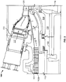
- Fig. 2 illustrates a partial view of an exemplary embodiment of a gas turbine 100 according to the present disclosure.
- the gas turbine 100 includes a compressor 112, a combustor 114, and a turbine 116.
- the compressor 112 includes compressor blades 112a and provides compressed air to the combustor 114. The direction of flow of the compressed air is generally shown by arrows A.
- Fuel is injected into the combustor 114 where it mixes with the compressed air and is ignited in a combustion chamber 117.
- the hot gas product of the combustion flows to the turbine 116, which extracts work from the hot gas by a plurality of turbine blades 120 that drive a shaft 118, which in turn drives the compressor 112.
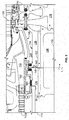
- Fig. 3 illustrates a more detailed view of a portion of Fig. 2 .
- the shaft 118 includes a first rotor shaft section 134, a second rotor shaft section 136, a rotor bore 138, and centerline 139.
- the first rotor shaft section 134 may be a compressor aft shaft.
- the second rotor shaft section 136 may be a turbine distance piece.
- the shaft 118 may include one or more rotor shaft sections.
- the shaft 18 may be a single, unitary rotor shaft section.
- the shaft 118 is at least partially disposed in a rotor shaft cavity 124.
- the rotor shaft cavity 124 is the space defined between the shaft 118 and turbine inner wall 126.
- the first and second rotor shaft sections 134, 136 are joined at an interface or joint 140.
- the first and second rotor shaft sections 134, 136 are joined by bolts 143.
- the first and second rotor shaft sections 134, 136 are joined by 30 bolts 143.
- the first and second rotor shaft sections 134, 136 may be joined by a plurality of bolts 143.
- the joint 140 may be a marriage joint, and the bolts 143 may be a plurality of marriage bolts.
- the shaft 118 may include two or more shaft sections connected at one or more joints. In another embodiment, the shaft 118 may include two or more shaft sections joined by one or more marriage joints.
- the shaft 118 includes cooling channels 122.
- the shaft 118 includes 15 cooling channels 122 (see Fig. 5 ).
- the shaft 118 may include one or more cooling channels.
- the cooling channels 122 are in fluid communication with the compressor 112 and the turbine 116.
- the cooling channels 122 pull or bleed air from the compressor 112 and provide the air to the turbine 116.
- the air is then provided to cool a plurality of turbine blades 120.
- the air may be provided to cool other components of the turbine 116.
- the flow of cooling air is generally shown by arrows B (see Fig. 3 ).
- air is bled from the air compressor flow path, which is generally shown by arrow C.
- air may be bled from another stationary or rotational structure or point of the gas turbine 100.
- air may be bled from a stationary or rotational structure or point of the compressor 112.
- air may be bled from an outer diameter extraction cavity 131 or the diffuser region 113.
- cooling channels 122 provide air to the turbine 116, and in particular to a rotor cavity 119.
- cooling channels 122 may provide air to another structure or point of the turbine 116.
- air may be provided to another stationary or rotational structure or point of the turbine 116.
- joint 140 is formed between the first and second rotor shaft sections 134, 136, where a first rotor shaft section end surface 144 and a second rotor shaft section end surface meet, join and contact.
- Cooling channels 122 traverses across and through joint 140 from the first rotor shaft section 134 to the second rotor shaft section 136, and more particularly, through first and second rotor shaft section surfaces 144, 146.
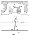
- Particle separation slots 148 are formed in the joint and defined by and between the first and second rotor shaft sections 134, 136. Particle separation slots 148 fluidly connect cooling channels 122 to inner barrel cavity 150, which is a section of the rotor shaft cavity 124 ( Fig. 2 ). Inner barrel cavity 150 is defined by the outer surface 157 of shaft 118 and the inner barrel surface 158 of an inner barrel 152.
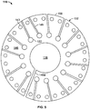
- Fig. 5 illustrates a sectional view of joint 140 taken along line L-L.
- Line L-L has been extended to section the whole shaft 118 of the partial view of the shaft 118 shown in Fig. 3 .
- joint holes 154 are uniformly, circumferentially distributed around the shaft 118.
- Particle separation slots 148 fluidly connect cooling channels 122 to the outer surface 156 of the shaft 118 and inner barrel cavity 150 ( Fig. 4 ).
- cooling fluid channels 122 connect a corresponding number of particle separation slots 148 to the outer surface 156.
- one or more particle separation slots 148 may connect one or more of the one or more cooling channels 122 to outer surface 156.
- Particle separation slots 148 divert between about 1 vol. % to about 10 vol. % of the airflow from the cooling channels 122 to the rotor shaft cavity 124 ( Fig. 2 ). In another embodiment, one or more particle separation slots 148 divert between about 1 volume percent (vol. %) to about 10 vol. % of the airflow from the cooling channels 122 to the inner barrel cavity 150. In another embodiment, one or more particle separation slots 148 divert between about 1 vol. % and about 6 vol. % of the airflow from the cooling channels 122 to the inner barrel cavity 150. In another embodiment, one or more particle separation slots 148 divert between about 1 vol. % and about 4 vol. % of the airflow from the cooling channels 122 to the inner barrel cavity 150. In yet another embodiment, one or more particle separation slots 148 divert about 1 vol. % of the airflow from the cooling channels 122 to the inner barrel cavity 150.
- another particle separation slot 148a fluidly connects rotor bore 138 to outer surface 156 and inner barrel cavity 150 ( Fig. 4 ).
- one or more another particle separation slots 148a may fluidly connect rotor bore 138 to outer surface 156.
- the another particle separation slot 148a may be omitted.
- the particle separation slots 148 may be initially cast or later machined into the joint 140.
- the particle separation slots 148 may be formed on one or both of the first rotor shaft end surface 144 and/or the second rotor shaft end surface 146.
- the particle separation slots 148 may be formed on both the first and second rotor shaft end surfaces 144, 146.
- corresponding particle separation slots 148 may be mirrored on the first and second rotor shaft end surfaces 144, 146 so as to both define the particle separation slots 148.
- the particle separation slots 148 are initially cast or machined into a solid portion of the shaft 118 at any position along the centerline 139 ( Fig. 2 ) in fluid communication between the cooling channels 122 and the rotor shaft cavity 124.
- contaminant particles may collect on inner barrel surface 158.
- contaminant particles flow from the particle separation slots 148, 148a into rotor shaft cavity 124.
- the contaminant particles may collect on turbine inner wall 126.
- air may be provided from the compressor 112 to the turbine 116 through rotor shaft cavity 124.
- the air may be provided by leakage, or as provided by engineered design.
- air is provided to the rotor shaft cavity 124 through rotating seal 160.
- air provided to the rotor shaft cavity 124 may remove some or all contaminant particles built up on inner barrel surface 158.
- air provided to the rotor shaft cavity 124 may remove some or all of contaminant particles from rotor shaft cavity 124.
- the contaminant particles removed from the inner barrel surface 158 and/or rotor shaft cavity 124 may be provided to the turbine 116.
- contaminant particles removed from the inner barrel surface 158 and/or rotor shaft cavity 124 may be provided to the turbine 116 where combustion gases pass through the turbine 116. In another embodiment, some or all of the contaminant particles maybe removed from the rotor shaft cavity 124 and provided to the turbine 168 and/or allowed to disperse and/or collect on other gas turbine components.
Landscapes
- Engineering & Computer Science (AREA)
- Mechanical Engineering (AREA)
- General Engineering & Computer Science (AREA)
- Structures Of Non-Positive Displacement Pumps (AREA)
- Separation Of Solids By Using Liquids Or Pneumatic Power (AREA)
- Centrifugal Separators (AREA)
Claims (9)
- Rotierende Maschine (10), umfassend:einen ersten Maschinenabschnitt (12, 112);einen zweiten Maschinenabschnitt (14, 116); undeinen rotierenden Maschinenabschnitt (16), einschließlich einer Rotorwelle (18, 118), die den ersten Maschinenabschnitt (12, 112) mit dem zweiten Maschinenabschnitt (14, 116) verbindet;wobei die Rotorwelle (18, 118) einen oder mehrere Kühlkanäle (22, 122) zum Bereitstellen von Kühlluft an den zweiten Maschinenabschnitt (14, 116) einschließt, wobei der eine oder die mehreren Kühlkanäle (22, 122) in Fluidverbindung zwischen dem ersten Maschinenabschnitt (12, 112) und dem zweiten Maschinenabschnitt (14, 116) stehen, wobei die Kühlluft von dem ersten Maschinenabschnitt (12, 112) an den einen oder die mehreren Kühlkanäle (22, 122) bereitgestellt wird;wobei ein oder mehrere Partikeltrennschlitze (24, 148), die in der Rotorwelle (18, 118) eingeschlossen sind, fluidmäßig einen oder mehrere des einen oder der mehreren Kühlkanäle (22, 122) mit einem Hohlraum (26, 124, 150) verbinden, der die Rotorwelle (18, 118) umgibt, wobei die Partikeltrennschlitze (24, 148) eingerichtet und angeordnet sind, um Strömung von einem Teil der Kühlluft zu dem Hohlraum (26, 124, 150) zu erleichtern und Partikel in die Partikeltrennschlitze (24, 148) zu drängen, wobei die Strömung der Partikel durch Zentrifugalkräfte erfolgt, die durch die rotierende Rotorwelle (18, 118) bereitgestellt werden; und wobei der eine oder die mehreren Partikeltrennschlitze (24, 148) zwischen etwa 1 Vol.-% und etwa 10 Vol.-% der Kühlluft aus dem einen oder den mehreren Kühlkanälen (22, 122) zu dem Hohlraum (26, 124, 150) umleiten.
- Rotierende Maschine nach Anspruch 1, wobei der eine oder die mehreren Partikeltrennschlitze (24) zwischen etwa 1 Vol.-% und etwa 4 Vol.-% der Kühlluft aus dem einen oder den mehreren Kühlkanälen (22, 122) umleiten.
- Rotierende Maschine nach Ansprüchen 1 oder 2, wobei die Rotorwelle (18) einen ersten Bereich (18a) umfasst, der mit einem zweiten Bereich (18b) an einer Verbindungsstelle (19) verbunden ist, und wobei der eine oder die mehreren Partikeltrennschlitze (24, 148) durch die Verbindungsstelle (19) hindurch angeordnet sind.
- Rotierende Maschine nach einem der vorstehenden Ansprüche, wobei der eine oder die mehreren Kühlkanäle (22, 122) Kühlluft an Komponenten des zweiten Maschinenabschnitts (14) bereitstellen.
- Gasturbine (100), umfassend die rotierende Maschine nach einem der Ansprüche 1 bis 4, wobei der erste Maschinenabschnitt einen Verdichter (12, 112) zum Verdichten eines Fluids umfasst;
der zweite Maschinenabschnitt eine Turbine (14, 116) zum Aufnehmen des Fluids nach der Verdichtung umfasst; und
die Rotorwelle den Verdichter (12, 112) mit der Turbine (14, 116) verbindet. - Gasturbine nach Anspruch 5, wobei die eine oder die mehreren Kühlkanäle (22, 122) Kühlluft an Turbinenschaufeln (120) der Turbine (14, 116) bereitstellen.
- Gasturbine nach Anspruch 5 oder 6, wobei der eine oder die mehreren Kühlkanäle (22, 122) ein Bohrloch durch die Rotorwelle (18, 118) umfassen.
- Gasturbine nach einem der Ansprüche 5 bis 7, ferner umfassend einen stationären Innenzylinder (152), der einen offenen Hohlraum (150) um eine Außenoberfläche (157) der Rotorwelle (18, 118) definiert, wobei der eine oder die mehreren Partikeltrennschlitze (24, 148) sich mit der Außenoberfläche verbinden.
- Verfahren zum Trennen von Schmutzpartikeln aus einem Strom von Kühlluft, umfassend:Bereitstellen einer rotierenden Maschine (10), umfassend einen ersten Maschinenabschnitt (12, 112), einen zweiten Maschinenabschnitt (14, 116) und einen rotierenden Maschinenabschnitt (16), der eine Rotorwelle (18, 118) einschließt;Extrahieren eines Kühlluftstroms aus dem ersten Maschinenabschnitt (12, 112);Bereitstellen des extrahierten Kühlluftstroms an den rotierenden Maschinenabschnitt (16), wobei die rotierende Rotorwelle (18, 118) einen oder mehrerer Kühlkanäle (22) zum Bereitstellen von Kühlluft an den zweiten Maschinenabschnitt (14) einschließt, wobei der eine oder die mehreren Kühlkanäle (22, 122) in Fluidverbindung zwischen dem ersten Maschinenabschnitt (12, 112) und dem zweiten Maschinenabschnitt (14, 116) stehen; und Bereitstellen des Kühlluftstrom aus dem rotierenden Maschinenabschnitt (16) an den zweiten Maschinenabschnitt (14, 116);wobei ein Teil des Kühlluftstroms über Partikeltrennschlitze, die in der Rotorwelle (18, 118) eingeschlossen sind, von dem rotierenden Maschinenabschnitt (16) in einen Hohlraum (26, 124, 150), der die Rotorwelle (18, 118) umgibt, umgeleitet wird, um Schmutzpartikel aus dem Kühlluftstrom zu entfernen, wobei die Partikeltrennschlitze (24, 148) eingerichtet und angeordnet sind, um Strömung eines Teils der Kühlluft zu dem Hohlraum (26, 124, 150) zu erleichtern und Partikel in die Partikeltrennschlitze (24, 148) zu drängen, wobei die Strömung der Partikel durch Zentrifugalkräfte erfolgt, die von der rotierenden Rotorwelle (18, 118) bereitgestellt werden; und wobei der eine oder die mehreren Partikeltrennschlitze (24, 148) zwischen etwa 1 Vol.-% und etwa 10 Vol.-% der Kühlluft aus dem einen oder den mehreren Kühlkanälen (22, 122) zu dem Hohlraum (26, 124, 150) umleiten.
Applications Claiming Priority (1)
| Application Number | Priority Date | Filing Date | Title |
|---|---|---|---|
| US13/030,187 US9206693B2 (en) | 2011-02-18 | 2011-02-18 | Apparatus, method, and system for separating particles from a fluid stream |
Publications (3)
| Publication Number | Publication Date |
|---|---|
| EP2489834A2 EP2489834A2 (de) | 2012-08-22 |
| EP2489834A3 EP2489834A3 (de) | 2014-07-23 |
| EP2489834B1 true EP2489834B1 (de) | 2020-09-16 |
Family
ID=45655771
Family Applications (1)
| Application Number | Title | Priority Date | Filing Date |
|---|---|---|---|
| EP12155465.3A Active EP2489834B1 (de) | 2011-02-18 | 2012-02-14 | Vorrichtung, Verfahren und System zum Trennen von Partikeln aus einem Fluidsstrom |
Country Status (3)
| Country | Link |
|---|---|
| US (1) | US9206693B2 (de) |
| EP (1) | EP2489834B1 (de) |
| CN (1) | CN102641626B (de) |
Families Citing this family (7)
| Publication number | Priority date | Publication date | Assignee | Title |
|---|---|---|---|---|
| US9528392B2 (en) * | 2013-05-10 | 2016-12-27 | General Electric Company | System for supporting a turbine nozzle |
| US9121299B2 (en) | 2013-06-05 | 2015-09-01 | General Electric Company | Axially retractable brush seal system |
| WO2014197343A1 (en) * | 2013-06-06 | 2014-12-11 | Dresser-Rand Company | Compressor having hollow shaft |
| US10227930B2 (en) | 2016-03-28 | 2019-03-12 | General Electric Company | Compressor bleed systems in turbomachines and methods of extracting compressor airflow |
| US10695704B2 (en) | 2016-07-20 | 2020-06-30 | General Electric Company | Multi-station debris separation system |
| US10816014B2 (en) | 2018-07-25 | 2020-10-27 | Honeywell International Inc. | Systems and methods for turbine engine particle separation |
| JP7242597B2 (ja) * | 2020-03-12 | 2023-03-20 | 東芝エネルギーシステムズ株式会社 | タービンロータ |
Citations (1)
| Publication number | Priority date | Publication date | Assignee | Title |
|---|---|---|---|---|
| EP0690202A2 (de) * | 1994-06-30 | 1996-01-03 | Mtu Motoren- Und Turbinen-Union MàNchen Gmbh | Einrichtung zur Abscheidung von Fremdpartikeln aus der den Laufschaufeln einer Turbine zuzuführenden Kühlluft |
Family Cites Families (28)
| Publication number | Priority date | Publication date | Assignee | Title |
|---|---|---|---|---|
| US2788951A (en) * | 1951-02-15 | 1957-04-16 | Power Jets Res & Dev Ltd | Cooling of turbine rotors |
| CH355327A (de) | 1959-07-27 | 1961-06-30 | Bbc Brown Boveri & Cie | Axialturbine, insbesondere Gasturbine |
| US3521431A (en) | 1969-04-28 | 1970-07-21 | Avco Corp | Particle separator for engine air inlets |
| US5117626A (en) | 1990-09-04 | 1992-06-02 | Westinghouse Electric Corp. | Apparatus for cooling rotating blades in a gas turbine |
| US5353721A (en) | 1991-07-15 | 1994-10-11 | Manufacturing And Technology Conversion International | Pulse combusted acoustic agglomeration apparatus and process |
| DE4324034A1 (de) | 1993-07-17 | 1995-01-19 | Abb Management Ag | Gasturbine mit gekühltem Rotor |
| US5472316A (en) | 1994-09-19 | 1995-12-05 | General Electric Company | Enhanced cooling apparatus for gas turbine engine airfoils |
| US5482435A (en) | 1994-10-26 | 1996-01-09 | Westinghouse Electric Corporation | Gas turbine blade having a cooled shroud |
| US6033450A (en) * | 1995-12-21 | 2000-03-07 | United Technologies Corporation | Deoiler shaft vortex separator |
| DE19632038A1 (de) | 1996-08-08 | 1998-02-12 | Asea Brown Boveri | Vorrichtung zur Abscheidung von Staubpartikeln |
| US5924843A (en) | 1997-05-21 | 1999-07-20 | General Electric Company | Turbine blade cooling |
| US6398833B1 (en) * | 2000-11-06 | 2002-06-04 | Pratt & Whitney Canada Corp. | Air/oil separator |
| EP1249578B1 (de) * | 2001-04-11 | 2006-10-11 | Siemens Aktiengesellschaft | Kühlung einer Gasturbine |
| DE102004061173B4 (de) | 2004-12-16 | 2013-12-05 | Rolls-Royce Deutschland Ltd & Co Kg | Gasturbinentriebwerk mit einem Partikelseparator |
| SE528750C2 (sv) * | 2005-06-27 | 2007-02-06 | 3Nine Ab | Förfarande och anordning för separering av partiklar ur ett gasflöde |
| US7717666B2 (en) | 2005-10-21 | 2010-05-18 | General Electric Company | Methods and apparatus for rotary machinery inspection |
| US7678165B2 (en) | 2006-12-28 | 2010-03-16 | General Electric Company | Particle separator using boundary layer control |
| CA2818043C (en) * | 2007-05-22 | 2015-06-30 | Ihi Corporation | Gas turbine engine |
| US7935164B2 (en) * | 2007-11-28 | 2011-05-03 | General Electric Company | Vortex air-oil separator system |
| US8292034B2 (en) * | 2007-11-28 | 2012-10-23 | General Electric Company | Air-oil separator |
| US8727702B2 (en) | 2008-05-30 | 2014-05-20 | United Technologies Corporation | Hoop snap spacer |
| DE102008029521A1 (de) | 2008-06-21 | 2009-12-24 | Man Nutzfahrzeuge Ag | Partikelabscheider sowie Verfahren zur Abscheidung von Partikeln aus einem Abgasstrom einer Brennkraftmaschine |
| US20100005804A1 (en) | 2008-07-11 | 2010-01-14 | General Electric Company | Combustor structure |
| US8047768B2 (en) | 2009-01-12 | 2011-11-01 | General Electric Company | Split impeller configuration for synchronizing thermal response between turbine wheels |
| US8262356B2 (en) * | 2009-01-30 | 2012-09-11 | General Electric Company | Rotor chamber cover member having aperture for dirt separation and related turbine |
| US8162007B2 (en) | 2009-02-27 | 2012-04-24 | General Electric Company | Apparatus, methods, and/or systems relating to the delivery of a fluid through a passageway |
| US8578720B2 (en) * | 2010-04-12 | 2013-11-12 | Siemens Energy, Inc. | Particle separator in a gas turbine engine |
| US8677766B2 (en) * | 2010-04-12 | 2014-03-25 | Siemens Energy, Inc. | Radial pre-swirl assembly and cooling fluid metering structure for a gas turbine engine |
-
2011
- 2011-02-18 US US13/030,187 patent/US9206693B2/en active Active
-
2012
- 2012-02-14 EP EP12155465.3A patent/EP2489834B1/de active Active
- 2012-02-16 CN CN201210041493.4A patent/CN102641626B/zh active Active
Patent Citations (1)
| Publication number | Priority date | Publication date | Assignee | Title |
|---|---|---|---|---|
| EP0690202A2 (de) * | 1994-06-30 | 1996-01-03 | Mtu Motoren- Und Turbinen-Union MàNchen Gmbh | Einrichtung zur Abscheidung von Fremdpartikeln aus der den Laufschaufeln einer Turbine zuzuführenden Kühlluft |
Also Published As
| Publication number | Publication date |
|---|---|
| US9206693B2 (en) | 2015-12-08 |
| CN102641626A (zh) | 2012-08-22 |
| EP2489834A3 (de) | 2014-07-23 |
| US20120210722A1 (en) | 2012-08-23 |
| EP2489834A2 (de) | 2012-08-22 |
| CN102641626B (zh) | 2015-09-16 |
Similar Documents
| Publication | Publication Date | Title |
|---|---|---|
| US8920128B2 (en) | Gas turbine engine cooling systems having hub-bleed impellers and methods for the production thereof | |
| EP2489834B1 (de) | Vorrichtung, Verfahren und System zum Trennen von Partikeln aus einem Fluidsstrom | |
| EP3543468B1 (de) | Turbinenspitzendeckbandanordnung mit mehreren deckbandsegmenten mit zwischensegmentdichtungsanordnung | |
| US10450951B2 (en) | Cyclonic separator for a turbine engine | |
| US10400627B2 (en) | System for cooling a turbine engine | |
| US9988936B2 (en) | Shroud assembly for a gas turbine engine | |
| US10267179B2 (en) | Dirt extraction apparatus for a gas turbine engine | |
| US9771870B2 (en) | Sealing features for a gas turbine engine | |
| US7017349B2 (en) | Gas turbine and bleeding method thereof | |
| US20140348664A1 (en) | Impingement-cooled turbine rotor | |
| CN110805617B (zh) | 流体支承件组件 | |
| CA2950274A1 (en) | Turbine engine, components, and methods of cooling same | |
| US11746695B2 (en) | Turbine engine with centrifugal compressor having impeller backplate offtake | |
| EP3396112A2 (de) | Kühlkanäle einer tragflächenplattform | |
| US10934845B2 (en) | Dual cooling airflow to blades | |
| US9080448B2 (en) | Gas turbine engine vanes | |
| JP2013249835A (ja) | タービンシステムのバケット用冷却組立体及び冷却方法 | |
| CA2992684A1 (en) | Turbine housing assembly | |
| EP3312392B1 (de) | Turbinendeckband und dichtungsanordnung | |
| CN117211894A (zh) | 用于涡轮发动机的密封组件 | |
| CN114251132A (zh) | 具有金属结构构件和复合整流罩的燃气涡轮发动机的转子叶片 |
Legal Events
| Date | Code | Title | Description |
|---|---|---|---|
| PUAI | Public reference made under article 153(3) epc to a published international application that has entered the european phase |
Free format text: ORIGINAL CODE: 0009012 |
|
| AK | Designated contracting states |
Kind code of ref document: A2 Designated state(s): AL AT BE BG CH CY CZ DE DK EE ES FI FR GB GR HR HU IE IS IT LI LT LU LV MC MK MT NL NO PL PT RO RS SE SI SK SM TR |
|
| AX | Request for extension of the european patent |
Extension state: BA ME |
|
| PUAL | Search report despatched |
Free format text: ORIGINAL CODE: 0009013 |
|
| AK | Designated contracting states |
Kind code of ref document: A3 Designated state(s): AL AT BE BG CH CY CZ DE DK EE ES FI FR GB GR HR HU IE IS IT LI LT LU LV MC MK MT NL NO PL PT RO RS SE SI SK SM TR |
|
| AX | Request for extension of the european patent |
Extension state: BA ME |
|
| RIC1 | Information provided on ipc code assigned before grant |
Ipc: F01D 25/00 20060101ALI20140616BHEP Ipc: F01D 5/08 20060101AFI20140616BHEP Ipc: F01D 9/06 20060101ALI20140616BHEP Ipc: F01D 25/32 20060101ALI20140616BHEP |
|
| 17P | Request for examination filed |
Effective date: 20150123 |
|
| RBV | Designated contracting states (corrected) |
Designated state(s): AL AT BE BG CH CY CZ DE DK EE ES FI FR GB GR HR HU IE IS IT LI LT LU LV MC MK MT NL NO PL PT RO RS SE SI SK SM TR |
|
| STAA | Information on the status of an ep patent application or granted ep patent |
Free format text: STATUS: EXAMINATION IS IN PROGRESS |
|
| 17Q | First examination report despatched |
Effective date: 20190710 |
|
| GRAP | Despatch of communication of intention to grant a patent |
Free format text: ORIGINAL CODE: EPIDOSNIGR1 |
|
| STAA | Information on the status of an ep patent application or granted ep patent |
Free format text: STATUS: GRANT OF PATENT IS INTENDED |
|
| INTG | Intention to grant announced |
Effective date: 20200417 |
|
| GRAS | Grant fee paid |
Free format text: ORIGINAL CODE: EPIDOSNIGR3 |
|
| GRAA | (expected) grant |
Free format text: ORIGINAL CODE: 0009210 |
|
| STAA | Information on the status of an ep patent application or granted ep patent |
Free format text: STATUS: THE PATENT HAS BEEN GRANTED |
|
| AK | Designated contracting states |
Kind code of ref document: B1 Designated state(s): AL AT BE BG CH CY CZ DE DK EE ES FI FR GB GR HR HU IE IS IT LI LT LU LV MC MK MT NL NO PL PT RO RS SE SI SK SM TR |
|
| REG | Reference to a national code |
Ref country code: GB Ref legal event code: FG4D |
|
| REG | Reference to a national code |
Ref country code: CH Ref legal event code: EP |
|
| REG | Reference to a national code |
Ref country code: DE Ref legal event code: R096 Ref document number: 602012072325 Country of ref document: DE |
|
| REG | Reference to a national code |
Ref country code: IE Ref legal event code: FG4D |
|
| REG | Reference to a national code |
Ref country code: AT Ref legal event code: REF Ref document number: 1314326 Country of ref document: AT Kind code of ref document: T Effective date: 20201015 |
|
| PG25 | Lapsed in a contracting state [announced via postgrant information from national office to epo] |
Ref country code: HR Free format text: LAPSE BECAUSE OF FAILURE TO SUBMIT A TRANSLATION OF THE DESCRIPTION OR TO PAY THE FEE WITHIN THE PRESCRIBED TIME-LIMIT Effective date: 20200916 Ref country code: FI Free format text: LAPSE BECAUSE OF FAILURE TO SUBMIT A TRANSLATION OF THE DESCRIPTION OR TO PAY THE FEE WITHIN THE PRESCRIBED TIME-LIMIT Effective date: 20200916 Ref country code: NO Free format text: LAPSE BECAUSE OF FAILURE TO SUBMIT A TRANSLATION OF THE DESCRIPTION OR TO PAY THE FEE WITHIN THE PRESCRIBED TIME-LIMIT Effective date: 20201216 Ref country code: GR Free format text: LAPSE BECAUSE OF FAILURE TO SUBMIT A TRANSLATION OF THE DESCRIPTION OR TO PAY THE FEE WITHIN THE PRESCRIBED TIME-LIMIT Effective date: 20201217 Ref country code: BG Free format text: LAPSE BECAUSE OF FAILURE TO SUBMIT A TRANSLATION OF THE DESCRIPTION OR TO PAY THE FEE WITHIN THE PRESCRIBED TIME-LIMIT Effective date: 20201216 Ref country code: SE Free format text: LAPSE BECAUSE OF FAILURE TO SUBMIT A TRANSLATION OF THE DESCRIPTION OR TO PAY THE FEE WITHIN THE PRESCRIBED TIME-LIMIT Effective date: 20200916 |
|
| REG | Reference to a national code |
Ref country code: AT Ref legal event code: MK05 Ref document number: 1314326 Country of ref document: AT Kind code of ref document: T Effective date: 20200916 |
|
| REG | Reference to a national code |
Ref country code: NL Ref legal event code: MP Effective date: 20200916 |
|
| PG25 | Lapsed in a contracting state [announced via postgrant information from national office to epo] |
Ref country code: RS Free format text: LAPSE BECAUSE OF FAILURE TO SUBMIT A TRANSLATION OF THE DESCRIPTION OR TO PAY THE FEE WITHIN THE PRESCRIBED TIME-LIMIT Effective date: 20200916 Ref country code: LV Free format text: LAPSE BECAUSE OF FAILURE TO SUBMIT A TRANSLATION OF THE DESCRIPTION OR TO PAY THE FEE WITHIN THE PRESCRIBED TIME-LIMIT Effective date: 20200916 |
|
| REG | Reference to a national code |
Ref country code: LT Ref legal event code: MG4D |
|
| PG25 | Lapsed in a contracting state [announced via postgrant information from national office to epo] |
Ref country code: RO Free format text: LAPSE BECAUSE OF FAILURE TO SUBMIT A TRANSLATION OF THE DESCRIPTION OR TO PAY THE FEE WITHIN THE PRESCRIBED TIME-LIMIT Effective date: 20200916 Ref country code: SM Free format text: LAPSE BECAUSE OF FAILURE TO SUBMIT A TRANSLATION OF THE DESCRIPTION OR TO PAY THE FEE WITHIN THE PRESCRIBED TIME-LIMIT Effective date: 20200916 Ref country code: LT Free format text: LAPSE BECAUSE OF FAILURE TO SUBMIT A TRANSLATION OF THE DESCRIPTION OR TO PAY THE FEE WITHIN THE PRESCRIBED TIME-LIMIT Effective date: 20200916 Ref country code: NL Free format text: LAPSE BECAUSE OF FAILURE TO SUBMIT A TRANSLATION OF THE DESCRIPTION OR TO PAY THE FEE WITHIN THE PRESCRIBED TIME-LIMIT Effective date: 20200916 Ref country code: PT Free format text: LAPSE BECAUSE OF FAILURE TO SUBMIT A TRANSLATION OF THE DESCRIPTION OR TO PAY THE FEE WITHIN THE PRESCRIBED TIME-LIMIT Effective date: 20210118 Ref country code: CZ Free format text: LAPSE BECAUSE OF FAILURE TO SUBMIT A TRANSLATION OF THE DESCRIPTION OR TO PAY THE FEE WITHIN THE PRESCRIBED TIME-LIMIT Effective date: 20200916 Ref country code: EE Free format text: LAPSE BECAUSE OF FAILURE TO SUBMIT A TRANSLATION OF THE DESCRIPTION OR TO PAY THE FEE WITHIN THE PRESCRIBED TIME-LIMIT Effective date: 20200916 |
|
| PG25 | Lapsed in a contracting state [announced via postgrant information from national office to epo] |
Ref country code: PL Free format text: LAPSE BECAUSE OF FAILURE TO SUBMIT A TRANSLATION OF THE DESCRIPTION OR TO PAY THE FEE WITHIN THE PRESCRIBED TIME-LIMIT Effective date: 20200916 Ref country code: AL Free format text: LAPSE BECAUSE OF FAILURE TO SUBMIT A TRANSLATION OF THE DESCRIPTION OR TO PAY THE FEE WITHIN THE PRESCRIBED TIME-LIMIT Effective date: 20200916 Ref country code: AT Free format text: LAPSE BECAUSE OF FAILURE TO SUBMIT A TRANSLATION OF THE DESCRIPTION OR TO PAY THE FEE WITHIN THE PRESCRIBED TIME-LIMIT Effective date: 20200916 Ref country code: ES Free format text: LAPSE BECAUSE OF FAILURE TO SUBMIT A TRANSLATION OF THE DESCRIPTION OR TO PAY THE FEE WITHIN THE PRESCRIBED TIME-LIMIT Effective date: 20200916 Ref country code: IS Free format text: LAPSE BECAUSE OF FAILURE TO SUBMIT A TRANSLATION OF THE DESCRIPTION OR TO PAY THE FEE WITHIN THE PRESCRIBED TIME-LIMIT Effective date: 20210116 |
|
| REG | Reference to a national code |
Ref country code: DE Ref legal event code: R097 Ref document number: 602012072325 Country of ref document: DE |
|
| PG25 | Lapsed in a contracting state [announced via postgrant information from national office to epo] |
Ref country code: SK Free format text: LAPSE BECAUSE OF FAILURE TO SUBMIT A TRANSLATION OF THE DESCRIPTION OR TO PAY THE FEE WITHIN THE PRESCRIBED TIME-LIMIT Effective date: 20200916 |
|
| PLBE | No opposition filed within time limit |
Free format text: ORIGINAL CODE: 0009261 |
|
| STAA | Information on the status of an ep patent application or granted ep patent |
Free format text: STATUS: NO OPPOSITION FILED WITHIN TIME LIMIT |
|
| 26N | No opposition filed |
Effective date: 20210617 |
|
| PG25 | Lapsed in a contracting state [announced via postgrant information from national office to epo] |
Ref country code: SI Free format text: LAPSE BECAUSE OF FAILURE TO SUBMIT A TRANSLATION OF THE DESCRIPTION OR TO PAY THE FEE WITHIN THE PRESCRIBED TIME-LIMIT Effective date: 20200916 Ref country code: DK Free format text: LAPSE BECAUSE OF FAILURE TO SUBMIT A TRANSLATION OF THE DESCRIPTION OR TO PAY THE FEE WITHIN THE PRESCRIBED TIME-LIMIT Effective date: 20200916 |
|
| PG25 | Lapsed in a contracting state [announced via postgrant information from national office to epo] |
Ref country code: MC Free format text: LAPSE BECAUSE OF FAILURE TO SUBMIT A TRANSLATION OF THE DESCRIPTION OR TO PAY THE FEE WITHIN THE PRESCRIBED TIME-LIMIT Effective date: 20200916 |
|
| GBPC | Gb: european patent ceased through non-payment of renewal fee |
Effective date: 20210214 |
|
| REG | Reference to a national code |
Ref country code: BE Ref legal event code: MM Effective date: 20210228 |
|
| PG25 | Lapsed in a contracting state [announced via postgrant information from national office to epo] |
Ref country code: LI Free format text: LAPSE BECAUSE OF NON-PAYMENT OF DUE FEES Effective date: 20210228 Ref country code: LU Free format text: LAPSE BECAUSE OF NON-PAYMENT OF DUE FEES Effective date: 20210214 Ref country code: CH Free format text: LAPSE BECAUSE OF NON-PAYMENT OF DUE FEES Effective date: 20210228 Ref country code: IT Free format text: LAPSE BECAUSE OF FAILURE TO SUBMIT A TRANSLATION OF THE DESCRIPTION OR TO PAY THE FEE WITHIN THE PRESCRIBED TIME-LIMIT Effective date: 20200916 |
|
| PG25 | Lapsed in a contracting state [announced via postgrant information from national office to epo] |
Ref country code: FR Free format text: LAPSE BECAUSE OF NON-PAYMENT OF DUE FEES Effective date: 20210228 Ref country code: GB Free format text: LAPSE BECAUSE OF NON-PAYMENT OF DUE FEES Effective date: 20210214 Ref country code: IE Free format text: LAPSE BECAUSE OF NON-PAYMENT OF DUE FEES Effective date: 20210214 |
|
| PG25 | Lapsed in a contracting state [announced via postgrant information from national office to epo] |
Ref country code: BE Free format text: LAPSE BECAUSE OF NON-PAYMENT OF DUE FEES Effective date: 20210228 |
|
| PG25 | Lapsed in a contracting state [announced via postgrant information from national office to epo] |
Ref country code: HU Free format text: LAPSE BECAUSE OF FAILURE TO SUBMIT A TRANSLATION OF THE DESCRIPTION OR TO PAY THE FEE WITHIN THE PRESCRIBED TIME-LIMIT; INVALID AB INITIO Effective date: 20120214 Ref country code: CY Free format text: LAPSE BECAUSE OF FAILURE TO SUBMIT A TRANSLATION OF THE DESCRIPTION OR TO PAY THE FEE WITHIN THE PRESCRIBED TIME-LIMIT Effective date: 20200916 |
|
| REG | Reference to a national code |
Ref country code: DE Ref legal event code: R081 Ref document number: 602012072325 Country of ref document: DE Owner name: GENERAL ELECTRIC TECHNOLOGY GMBH, CH Free format text: FORMER OWNER: GENERAL ELECTRIC COMPANY, SCHENECTADY, NY, US |
|
| PG25 | Lapsed in a contracting state [announced via postgrant information from national office to epo] |
Ref country code: MK Free format text: LAPSE BECAUSE OF FAILURE TO SUBMIT A TRANSLATION OF THE DESCRIPTION OR TO PAY THE FEE WITHIN THE PRESCRIBED TIME-LIMIT Effective date: 20200916 |
|
| PG25 | Lapsed in a contracting state [announced via postgrant information from national office to epo] |
Ref country code: TR Free format text: LAPSE BECAUSE OF FAILURE TO SUBMIT A TRANSLATION OF THE DESCRIPTION OR TO PAY THE FEE WITHIN THE PRESCRIBED TIME-LIMIT Effective date: 20200916 |
|
| PG25 | Lapsed in a contracting state [announced via postgrant information from national office to epo] |
Ref country code: MT Free format text: LAPSE BECAUSE OF FAILURE TO SUBMIT A TRANSLATION OF THE DESCRIPTION OR TO PAY THE FEE WITHIN THE PRESCRIBED TIME-LIMIT Effective date: 20200916 |
|
| PGFP | Annual fee paid to national office [announced via postgrant information from national office to epo] |
Ref country code: DE Payment date: 20250122 Year of fee payment: 14 |