EP2489479A1 - Handgeführtes Arbeitsgerät - Google Patents
Handgeführtes Arbeitsgerät Download PDFInfo
- Publication number
- EP2489479A1 EP2489479A1 EP12000771A EP12000771A EP2489479A1 EP 2489479 A1 EP2489479 A1 EP 2489479A1 EP 12000771 A EP12000771 A EP 12000771A EP 12000771 A EP12000771 A EP 12000771A EP 2489479 A1 EP2489479 A1 EP 2489479A1
- Authority
- EP
- European Patent Office
- Prior art keywords
- temperature
- display device
- temperature information
- cylinder
- detecting
- Prior art date
- Legal status (The legal status is an assumption and is not a legal conclusion. Google has not performed a legal analysis and makes no representation as to the accuracy of the status listed.)
- Granted
Links
- 238000002485 combustion reaction Methods 0.000 claims abstract description 21
- 239000004973 liquid crystal related substance Substances 0.000 claims description 13
- 239000000126 substance Substances 0.000 claims description 6
- 230000002349 favourable effect Effects 0.000 description 2
- 239000011888 foil Substances 0.000 description 2
- 239000002828 fuel tank Substances 0.000 description 2
- 239000012528 membrane Substances 0.000 description 2
- 239000000203 mixture Substances 0.000 description 2
- 229920003023 plastic Polymers 0.000 description 2
- 230000015572 biosynthetic process Effects 0.000 description 1
- 238000001514 detection method Methods 0.000 description 1
- 238000009413 insulation Methods 0.000 description 1
- 238000005259 measurement Methods 0.000 description 1
- 239000002184 metal Substances 0.000 description 1
- 238000005192 partition Methods 0.000 description 1
- 230000001681 protective effect Effects 0.000 description 1
- 230000005855 radiation Effects 0.000 description 1
Images
Classifications
-
- B—PERFORMING OPERATIONS; TRANSPORTING
- B25—HAND TOOLS; PORTABLE POWER-DRIVEN TOOLS; MANIPULATORS
- B25F—COMBINATION OR MULTI-PURPOSE TOOLS NOT OTHERWISE PROVIDED FOR; DETAILS OR COMPONENTS OF PORTABLE POWER-DRIVEN TOOLS NOT PARTICULARLY RELATED TO THE OPERATIONS PERFORMED AND NOT OTHERWISE PROVIDED FOR
- B25F5/00—Details or components of portable power-driven tools not particularly related to the operations performed and not otherwise provided for
- B25F5/02—Construction of casings, bodies or handles
-
- B—PERFORMING OPERATIONS; TRANSPORTING
- B25—HAND TOOLS; PORTABLE POWER-DRIVEN TOOLS; MANIPULATORS
- B25F—COMBINATION OR MULTI-PURPOSE TOOLS NOT OTHERWISE PROVIDED FOR; DETAILS OR COMPONENTS OF PORTABLE POWER-DRIVEN TOOLS NOT PARTICULARLY RELATED TO THE OPERATIONS PERFORMED AND NOT OTHERWISE PROVIDED FOR
- B25F5/00—Details or components of portable power-driven tools not particularly related to the operations performed and not otherwise provided for
Definitions
- the invention relates to a hand-held implement of the type specified in the preamble of claim 1.
- a power saw which has a display device for displaying operating or state parameters of the power plant. It is also known to arrange a temperature sensor on hand-held work tools on the cylinder or crankcase. However, energy is needed to operate the temperature sensor. Hand-held implements are often operated without an additional power supply such as a battery or a rechargeable battery. The only energy is supplied by the internal combustion engine. At standstill of the internal combustion engine, the temperature sensor without power supply and thus out of service.
- the operator can usually choose between a cold start setting and a warm start setting at start up.
- the start setting depends essentially on how much time has passed since the last operation of the internal combustion engine.
- the ambient temperature also plays a role. Especially for inexperienced users, it is not always clear whether a machine that has been stopped for some time can still be started under hot start conditions or whether a cold start is required. When starting a still warm machine under cold start conditions, it can lead to over-greasing, so that starting is only possible with difficulty.
- the invention has for its object to provide a hand-held implement of the generic type, in which the operator can easily determine whether a warm start or a cold start is set.
- the cylinder temperature itself need not be measured, but the temperature in a cylinder space is sufficient. Since the temperature in the cylinder chamber is significantly lower than the cylinder temperature itself, the temperature in the cylinder chamber can be detected by simple means.
- the display device allows the operator to select the most favorable start setting.
- the means for detecting the temperature information can also be active during operation of the internal combustion engine. For the display of cold start or warm start conditions, however, the detection of the temperature information during operation of the internal combustion engine of minor importance. It can therefore be provided that the means for detecting the temperature information during operation are switched off or can be switched off by the operator.
- the temperature information indicates whether the temperature is above or below a temperature threshold.
- a temperature threshold There is no need to record or measure an absolute temperature for the indication of cold start conditions or hot start conditions. It is sufficient to determine if the prevailing temperature is above or below a temperature threshold. At temperatures below the temperature threshold, cold start conditions prevail and at temperatures above the temperature threshold, hot start conditions prevail.
- the means for detecting the temperature information and the display device can be made simple.
- the engine is to start below a switching temperature of the cylinder in a cold start setting and above the switching temperature in a warm start setting. For whether the operator has the cold start setting or warm start setting set, for example, by adjusting a mode selector in a cold start position or a hot start position, it depends on the cylinder temperature accordingly.
- the means for detecting the temperature information are advantageously arranged on the working device such that the temperature threshold prevails at the means for detecting the temperature information when the switching temperature prevails at the cylinder.
- the intended arrangement of the means for detecting the temperature information can be determined by simple means, whether the cylinder temperature is above or below the switching temperature.
- the display device is advantageously visible from the outside of the housing.
- a simple design results when the means for detecting the temperature information are integrated into the display device.
- the means for detecting the temperature information and the display device advantageously comprise a thermochromic substance.
- Thermochromic substances are substances that change color depending on the temperature. This can be displayed in a simple manner, whether the temperature in the cylinder chamber is above or below a temperature threshold. For thermochromic substances, no power supply is needed so that the temperature information can be displayed when the internal combustion engine is at a standstill.
- a particularly simple and favorable design results when the means for detecting the temperature information and the display device are formed by a film display with liquid crystals.
- the cylinder chamber is at least partially covered by a hood, wherein the means for detecting the temperature information and the display device are arranged on a cylinder space limiting region of the hood.
- a foil display can be glued to the hood become.
- the means for detecting the temperature information adjacent to the cylinder are arranged on the hood.
- the range is selected so that the changeover point of the slide display, which corresponds to the temperature threshold, coincides with the change of start conditions between cold start conditions and warm start conditions.
- the implement has in particular a handle bar, which engages over the housing.
- the display device is at least partially disposed below the handle bracket. As a result, the display device is at least partially shaded by the handle, and the influence of direct sunlight is reduced.
- the means for detecting the temperature information are arranged at a distance from the cylinder space and are connected to the cylinder space via a heat-conducting element.
- the implement has a mode selector, via which in particular warm start conditions and cold start conditions can be set.
- the display device is advantageously arranged adjacent to the mode selector. This will indicate to the operator directly at the location of the operation to be performed how to adjust the mode selector.
- the means for detecting the temperature information comprise at least two elements with different thermal characteristics, that is to say different turning point and / or different color change.
- one of the elements is associated with a cold start symbol and the other of the elements with a warm start symbol.
- a particularly simple operation results when at least one symbol is arranged on the mode selector, wherein the at least one symbol on the mode selector corresponds to a symbol of the display device.
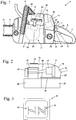
- Fig. 1 shows as an exemplary embodiment of a hand-held implement 1, a chainsaw.
- the implement may also be a cut-off grinder, a brush cutter or the like.
- the working device 1 has a housing 2, in which an internal combustion engine 11 is arranged.
- the internal combustion engine 11 may be, for example, a two-stroke engine or a four-cycle engine.
- the housing 2 has a hood 18 which is formed in a housing 2, in Fig. 2 cylinder chamber 31 shown closes.
- the implement 1 has a rear handle 4, on which a throttle lever 5 and a throttle lock 6 are pivotally mounted. Adjacent to the rear handle 4, a mode selector 7 is arranged on the housing 2, which is pivotable in the direction of an arrow 29.
- the mode selector 7 has a stop position, an operating position, a warm start position, and a cold start position. Adjacent to the mode selector 7, a stop symbol 34, an operating symbol 33, a cold start symbol 23 and a warm start symbol 24 are arranged on the housing 2 assigned to corresponding positions of the mode selector 7.
- a guide rail 9 protrudes from, on which a saw chain 10 driven by the internal combustion engine 11 is arranged.
- the housing 2 is overlapped by a handle 8, which runs at a distance from the housing 2.
- the engine 11 draws in combustion air via an air filter 16 and a carburetor 12.
- the air filter 16 is in an in Fig. 2 shown carburetor 32 arranged in the embodiment according to Fig. 1 is closed by a separate air filter cover 17.
- the air filter cover 17 may also be integrally formed on the hood 18 so that the hood 18 covers both the cylinder chamber 31 and the gasifier chamber 32.
- the internal combustion engine 11 has a crankcase 20 and a cylinder 19.
- the internal combustion engine 11 also has an ignition module 13 which is connected to a spark plug 14.
- the spark plug 14 protrudes into a combustion chamber formed in the cylinder 19 and ignites the mixture in the combustion chamber.
- a display device 22 Adjacent to the rear handle 4, the implement also has a fuel tank 21 on the cylinder 19 is the in Fig. 2 shown exhaust muffler 15 is arranged.
- the cylinder chamber 31 and the gasifier chamber 32 are substantially separated from a partition wall 30.
- high temperatures prevail, since the cylinder chamber 31 is heated by the cylinder 19.
- the carburetor chamber 32 is relatively cold in contrast. This can prevent vapor bubble formation in the mixture system.
- the display device 22 is disposed on the hood 18 adjacent to the cylinder chamber 31, in particular directly above the cylinder 19. The temperature of this region of the hood 18 is determined substantially by the cylinder temperature 19. In contrast, the influence of the ambient temperature can be largely neglected.
- the display device 22 also includes means for detecting the temperature of the cylinder chamber 31.
- the display device 22 has this advantageous a thermochromic substance. These are in particular liquid crystals.
- the Display device 22 is in particular a film display with liquid crystals. It has been found that when the display device 22 is mounted above the cylinder 19 on the hood 18, a film display can be used to indicate cold start conditions or hot start conditions where the turnup temperature is in the range between about 20 ° C to about 30 ° C. As a result, commercial film displays can be used, as they are also used in film thermometers to indicate cold start conditions or hot start conditions for the operator. Cold start conditions prevail when the temperature of the cylinder 19 is below a switching temperature and warm start conditions when the temperature of the cylinder 19 is above the switching temperature.
- the display device 22 is arranged on the hood 18, that prevails at the display device 22, the Umtschtemperatur the film display when the cylinder 19, the switching temperature prevails.
- the display device 22 can be used to indicate whether cold start conditions or warm start conditions prevail.
- the display device 22 'at may also be advantageous to arrange the display device 22 'at a distance from the cylinder space 31.
- the cylinder space 31 can be connected to the display device 22 'via a heat-conducting element 42.
- the temperature of the cylinder chamber 31 is directed to the display device 22.
- the heat-conducting element 42 may be, for example, an insulated metal wire or the like.
- a suitable space can also be created in the hand-held tool on or in which the film display is arranged.
- the display device 22 is then arranged adjacent to the mode selector 7 or directly on the mode selector 7.
- Foil displays indicate the temperature relative to a temperature threshold. Below the temperature threshold, the liquid crystals have a first color and above the temperature threshold, a second color.
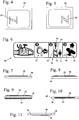
- Fig. 3 shows an embodiment of a display device 22 having a cold start symbol 23 and a warm start symbol 24.
- the areas of cold-start symbol 23 and hot-start symbol 24 are deposited with liquid crystals of different color.
- the cold start symbol 23 is deposited with a liquid crystal that is blue below the temperature threshold and the area of the warm start symbol 24 with a liquid crystal that is red above a temperature threshold.
- the Umschlagemperaturen for the two liquid crystals may overlap or be spaced from each other. If none of the symbols 23 and 24 are displayed or both symbols 23, 24 are displayed, the user can start both in the cold start and in the warm start.
- Fig. 4 shows the display device 22 at cold start conditions.
- the liquid crystals in the region of the cold start symbol 23 shine, for example blue.
- the liquid crystals in the region of the warm start symbol 24 have the same color as the background at this temperature, so that the hot start symbol 24 is not displayed.
- Fig. 5 shows the display device 22 at warm start conditions.
- the liquid crystals in the region of the cold start symbol 23 have the color of the background and the liquid crystals in the region of the warm start symbol 24 stand out in color from the background, for example in red. A particularly advantageous black background has been found.
- Fig. 6 shows an example of a possible user guide 28, which may be glued as a sticker on the outside of the implement 1, for example, to facilitate the start of the operator.
- a purgers icon 25 is shown, which signals to the operator that the purger is to be pressed five times.
- an adjustment symbol 26 is shown, which shows a stop symbol 34, an operating symbol 33, the warm start symbol 24 and the cold start symbol 23.
- the symbols 23, 24, 33 and 34 shown here correspond to the symbols adjacent to the mode selector.
- the mode selector 7 is also shown schematically in field 2.
- the field 3 contains a start symbol 27, which signals to the operator that a control handle 35 of a starting device of the working device 1 is to be actuated after adjustment of the operating mode actuator 7.
- the mode selector 7 and the operator guide 28 while the same symbols 23, 24 are provided for cold start and warm start.
- FIGS. 7 to 11 show different possibilities of arrangement of the display device 22.
- the display device 22 namely a film thermometer which both detects and displays the temperature information, is glued onto the hood 18.
- the display device 22 is also glued to the hood 18 and additionally covered by a protective film 36.
- a thermal insulation 37 may be arranged on the inside of the hood 18. This is particularly useful when the temperatures on the outside of the hood 18 are too high and can damage the display device 22 or indicate hot start conditions already at temperatures where cold start conditions prevail.
- the display device 22 can be arranged in a recess 39 of the hood 18.
- a window 38 can be set, which may for example consist of a transparent plastic and the display device 22 covers upwards and flush with the Outside of the hood 18 completes. Characterized in that the display device 22 is connected only via a thinner plastic layer of the hood 18 with the cylinder chamber 31, higher temperatures can be achieved on the display device 22.
- the display device 22 on the inside of the hood 18, that is arranged in the cylinder chamber 31. So that the display device 22 is clearly visible from the outside of the housing 2, the display device 22 is arranged on a window 40 which is fixed in a recess 41 of the hood 18.
- the display device 22 has only one symbol for cold start or warm start. If the indicator has an icon for warm start conditions, cold start conditions should be set if no icon is shown. Accordingly, in a display device 22 having only one icon for cold start conditions, the warm start must be set if no icon is displayed.
- the display device 22 is inactive or switched off during operation. This is expedient in particular in the case of an electrical display device 22 such as an LED or a display. A display device which can be switched off by the operator can also be advantageous.
Landscapes
- Engineering & Computer Science (AREA)
- Mechanical Engineering (AREA)
- Portable Power Tools In General (AREA)
- Instrument Panels (AREA)
- Measuring Temperature Or Quantity Of Heat (AREA)
- Devices For Indicating Variable Information By Combining Individual Elements (AREA)
- Numerical Control (AREA)
Abstract
Description
- Die Erfindung betrifft ein handgeführtes Arbeitsgerät der im Oberbegriff des Anspruchs 1 angegebenen Gattung.
- Aus der
DE 203 16 470 U1 ist eine Motorsäge bekannt, die eine Anzeigeeinrichtung zur Anzeige von Betriebs- oder Zustandsparametem des Antriebsaggregats besitzt. Es ist auch bekannt, bei handgeführten Arbeitsgeräten am Zylinder oder Kurbelgehäuse einen Temperatursensor anzuordnen. Zum Betrieb des Temperatursensors wird allerdings Energie benötigt. Handgeführte Arbeitsgeräte werden in vielen Fällen ohne eine zusätzliche Energieversorgung wie beispielsweise eine Batterie oder einen Akku betrieben. Die einzige Energie wird durch den Verbrennungsmotor geliefert. Bei Stillstand des Verbrennungsmotors ist der Temperatursensor ohne Energieversorgung und dadurch außer Betrieb. - Bei handgeführten Arbeitsgeräten kann der Bediener üblicherweise zwischen einer Kaltstarteinstellung und einer Warmstarteinstellung beim Starten wählen. Die Starteinstellung ist wesentlich abhängig davon, wie viel Zeit seit dem letzten Betrieb des Verbrennungsmotors vergangen ist. Die Umgebungstemperatur spielt ebenfalls eine Rolle. Vor allem für ungeübte Benutzer ist nicht immer ersichtlich, ob eine seit einiger Zeit stillstehende Maschine noch unter Warmstartbedingungen gestartet werden kann oder ob ein Kaltstart erforderlich ist. Beim Starten einer noch warmen Maschine unter Kaltstartbedingungen kann es zu einem Überfetten kommen, so dass ein Starten nur erschwert möglich ist.
- Der Erfindung liegt die Aufgabe zugrunde, ein handgeführtes Arbeitsgerät der gattungsgemäßen Art zu schaffen, bei dem der Bediener auf einfache Weise feststellen kann, ob ein Warmstart oder ein Kaltstart einzustellen ist.
- Diese Aufgabe wird durch ein handgeführtes Arbeitsgerät mit den Merkmalen des Anspruchs 1 gelöst.
- Es hat sich gezeigt, dass für eine ausreichend zuverlässige Anzeige, ob Kaltstartbedingungen oder Warmstartbedingungen herrschen, nicht die Zylindertemperatur selbst gemessen werden muss, sondern die Temperatur in einem Zylinderraum ausreichend ist. Da die Temperatur in dem Zylinderraum deutlich niedriger liegt als die Zylindertemperatur selbst, kann die Temperatur in dem Zylinderraum mit einfachen Mitteln erfasst werden. Die Anzeigeeinrichtung ermöglicht dem Bediener, die günstigste Starteinstellung zu wählen. Die Mittel zur Erfassung der Temperaturinformation können dabei auch im Betrieb des Verbrennungsmotors aktiv sein. Für die Anzeige von Kaltstart- oder Warmstartbedingungen ist die Erfassung der Temperaturinformation beim Betrieb des Verbrennungsmotors jedoch von untergeordneter Bedeutung. Es kann deshalb vorgesehen sein, dass die Mittel zur Erfassung der Temperaturinformation im Betrieb abgeschaltet oder vom Bediener abschaltbar sind.
- Vorteilhaft gibt die Temperaturinformation an, ob die Temperatur oberhalb oder unterhalb eines Temperaturschwellwerts liegt. Für die Anzeige, ob Kaltstartbedingungen oder Warmstartbedingungen herrschen, muss keine absolute Temperatur erfasst oder gemessen werden. Es ist ausreichend, zu ermitteln, ob die herrschende Temperatur oberhalb oder unterhalb eines Temperaturschwellwerts liegt. Bei Temperaturen unterhalb des Temperaturschwellwerts herrschen Kaltstartbedingungen und bei Temperaturen oberhalb des Temperaturschwellwerts Warmstartbedingungen. Dadurch können die Mittel zur Erfassung der Temperaturinformation und die Anzeigeeinrichtung einfach gestaltet werden. Vorteilhaft ist der Verbrennungsmotor unterhalb einer Umschalttemperatur des Zylinders in einer Kaltstarteinstellung zu starten und oberhalb der Umschalttemperatur in einer Warmstarteinstellung. Dafür, ob der Bediener die Kaltstarteinstellung oder Warmstarteinstellung einstellen muss, beispielsweise durch Verstellen eines Betriebsartenstellers in eine Kaltstartstellung oder eine Warmstartstellung, kommt es demnach auf die Zylindertemperatur an. Die Mittel zur Erfassung der Temperaturinformation sind vorteilhaft so an dem Arbeitsgerät angeordnet, dass an den Mitteln zur Erfassung der Temperaturinformation der Temperaturschwellwert herrscht, wenn an dem Zylinder die Umschalttemperatur herrscht. Durch die vorgesehene Anordnung der Mittel zur Erfassung der Temperaturinformation kann dadurch mit einfachen Mitteln ermittelt werden, ob die Zylindertemperatur oberhalb oder unterhalb der Umschalttemperatur liegt.
- Die Anzeigeeinrichtung ist dabei vorteilhaft von der Außenseite des Gehäuses aus sichtbar. Eine einfache Gestaltung ergibt sich, wenn die Mittel zur Erfassung der Temperaturinformation in die Anzeigeeinrichtung integriert sind. Die Mittel zur Erfassung der Temperaturinformation und die Anzeigeeinrichtung umfassen vorteilhaft einen thermochromen Stoff. Thermochrome Stoffe sind Stoffe, die in Abhängigkeit der Temperatur ihre Farbe wechseln. Dadurch kann auf einfache Weise angezeigt werden, ob die Temperatur in dem Zylinderraum oberhalb oder unterhalb eines Temperaturschwellwerts liegt. Für thermochrome Stoffe wird keine Energieversorgung benötigt, so dass die Temperaturinformation bei Stillstand des Verbrennungsmotors angezeigt werden kann. Eine besonders einfache und günstige Gestaltung ergibt sich, wenn die Mittel zur Erfassung der Temperaturinformation und die Anzeigeeinrichtung durch eine Folienanzeige mit Flüssigkristallen gebildet sind. Dadurch, dass nicht direkt die Zylindertemperatur gemessen wird, sondern die Temperatur in einem Zylinderraum, sind gängige Folienanzeigen, wie sie beispielsweise in Folienthermometern zum Einsatz kommen, einsetzbar. Im Unterschied zu Folienthermometern, die die Temperatur in Temperaturschritten von beispielsweise 2°C mit unterschiedlichen Elementen anzeigen, ist für die vorgesehene Folienanzeige ein Temperaturbereich, also ein Element eines Folienthermometers, ausreichend.
- Vorteilhaft ist der Zylinderraum mindestens teilweise von einer Haube abgedeckt, wobei die Mittel zur Erfassung der Temperaturinformation und die Anzeigeeinrichtung an einem den Zylinderraum begrenzenden Bereich der Haube angeordnet sind. Dadurch ergibt sich ein einfacher Aufbau. Insbesondere kann auf die Haube eine Folienanzeige aufgeklebt werden. Um an den Mitteln zur Erfassung der Temperaturinformation ausreichend hohe Temperaturen und ausreichend schnelle Temperaturschwankungen zu erzielen, ist vorgesehen, dass die Mittel zur Erfassung der Temperaturinformation benachbart zum Zylinder an der Haube angeordnet sind. Der Bereich ist so gewählt, dass der Umschlagpunkt der Folienanzeige, der dem Temperaturschwellwert entspricht, mit dem Wechsel der Startbedingungen zwischen Kaltstartbedingungen und Warmstartbedingungen übereinstimmt. Das Arbeitsgerät besitzt insbesondere einen Griffbügel, der das Gehäuse übergreift. Um den Einfluss der Sonneneinstrahlung auf das Messergebnis zu verringern, ist vorgesehen, dass die Anzeigeeinrichtung mindestens teilweise unterhalb des Griffbügels angeordnet ist. Dadurch ist die Anzeigeeinrichtung von dem Griffbügel mindestens teilweise beschattet, und der Einfluss der direkten Sonneneinstrahlung wird reduziert.
- Es kann auch vorteilhaft sein, dass die Mittel zur Erfassung der Temperaturinformation beabstandet zum Zylinderraum angeordnet sind und über ein Wärmeleitelement mit dem Zylinderraum verbunden sind. Vorteilhaft besitzt das Arbeitsgerät einen Betriebsartensteller, über den insbesondere Warmstartbedingungen und Kaltstartbedingungen einstellbar sind. Die Anzeigeeinrichtung ist vorteilhaft benachbart zu dem Betriebsartensteller angeordnet. Dadurch wird dem Bediener direkt am Ort der auszuführenden Bedienung angezeigt, wie der Betriebsartensteller zu verstellen ist. Vorteilhaft umfassen die Mittel zur Erfassung der Temperaturinformation mindestens zwei Elemente mit unterschiedlicher thermischer Charakteristik, also unterschiedlichem Umschlagpunkt und/oder unterschiedlichem Farbumschlag. Vorteilhaft ist einem der Elemente ein Kaltstartsymbol zugeordnet und dem anderen der Elemente ein Warmstartsymbol. Eine besonders einfache Bedienung ergibt sich, wenn auch an dem Betriebsartensteller mindestens ein Symbol angeordnet ist, wobei das mindestens eine Symbol an dem Betriebsartensteller einem Symbol der Anzeigeeinrichtung entspricht.
- Ausführungsbeispiele der Erfindung werden im Folgenden anhand der Zeichnung erläutert. Es zeigen:
- Fig. 1
- eine schematische Seitenansicht einer Motorsäge,
- Fig. 2
- eine schematische Darstellung eines Ausführungsbeispiels einer Motorsäge,
- Fig. 3
- eine schematische Darstellung einer Anzeigeeinrichtung,
- Fig. 4
- die Anzeigeeinrichtung aus
Fig. 3 bei Kaltstartbedingungen, - Fig. 5
- die Anzeigeeinrichtung aus
Fig. 3 bei Warmstartbedingungen, - Fig. 6
- eine schematische Darstellung einer Bedienerführung,
- Fig. 7 bis 11
- schematische Schnittdarstellungen durch Ausführungsbeispiele der Anordnung der Anzeigeeinrichtung.
-
Fig. 1 zeigt als Ausführungsbeispiel für ein handgeführtes Arbeitsgerät 1 eine Motorsäge. Das Arbeitsgerät kann jedoch auch ein Trennschleifer, ein Freischneider oder dgl. sein. Das Arbeitsgerät 1 besitzt ein Gehäuse 2, in dem ein Verbrennungsmotor 11 angeordnet ist. Der Verbrennungsmotor 11 kann beispielsweise ein Zweitaktmotor oder ein Viertaktmotor sein. Das Gehäuse 2 besitzt eine Haube 18, die einen im Gehäuse 2 ausgebildeten, inFig. 2 gezeigten Zylinderraum 31 verschließt. - Das Arbeitsgerät 1 besitzt einen hinteren Handgriff 4, an dem ein Gashebel 5 und eine Gashebelsperre 6 schwenkbar gelagert sind. Benachbart zum hinteren Handgriff 4 ist am Gehäuse 2 ein Betriebsartensteller 7 angeordnet, der in Richtung eines Pfeils 29 verschwenkbar ist. Der Betriebsartensteller 7 besitzt eine Stoppposition, eine Betriebsposition, eine Warmstartposition und eine Kaltstartposition. Benachbart zum Betriebsartensteller 7 sind am Gehäuse 2 zugeordnet zu entsprechenden Stellungen des Betriebsartenstellers 7 ein Stoppsymbol 34, ein Betriebssymbol 33, ein Kaltstartsymbol 23 und ein Warmstartsymbol 24 angeordnet.
- An der dem hinteren Handgriff 4 abgewandten Seite ragt eine Führungsschiene 9 nach vom, an der eine vom Verbrennungsmotor 11 angetriebene Sägekette 10 angeordnet ist. An der der Führungsschiene 9 zugewandten Seite ist das Gehäuse 2 von einem Griffbügel 8 übergriffen, der in einem Abstand zum Gehäuse 2 verläuft.
- Der Verbrennungsmotor 11 saugt Verbrennungsluft über einen Luftfilter 16 und einen Vergaser 12 an. Der Luftfilter 16 ist in einem in
Fig. 2 gezeigten Vergaserraum 32 angeordnet, der im Ausführungsbeispiel nachFig. 1 von einem separaten Luftfilterdeckel 17 verschlossen ist. WieFig. 2 zeigt, kann der Luftfilterdeckel 17 jedoch auch an der Haube 18 angeformt sein, so dass die Haube 18 sowohl den Zylinderraum 31 als auch den Vergaserraum 32 abdeckt. - Wie
Fig. 1 zeigt, besitzt der Verbrennungsmotor 11 ein Kurbelgehäuse 20 und einen Zylinder 19. Der Verbrennungsmotor 11 besitzt außerdem ein Zündmodul 13, das mit einer Zündkerze 14 verbunden ist. Die Zündkerze 14 ragt in einen im Zylinder 19 ausgebildeten Brennraum und zündet das Gemisch im Brennraum. WieFig. 1 zeigt, ist benachbart zum Zylinder 19 an der Haube 18 eine Anzeigeeinrichtung 22 angeordnet. Benachbart zum hinteren Handgriff 4 besitzt das Arbeitsgerät außerdem noch einen Kraftstofftank 21. Am Zylinder 19 ist der inFig. 2 gezeigte Abgasschalldämpfer 15 angeordnet. - Wie
Fig. 2 zeigt, sind der Zylinderraum 31 und der Vergaserraum 32 von einer Trennwand 30 im Wesentlichen getrennt. Im Zylinderraum 31 herrschen hohe Temperaturen, da der Zylinderraum 31 vom Zylinder 19 aufgeheizt wird. Der Vergaserraum 32 ist demgegenüber vergleichsweise kalt. Dadurch kann eine Dampfblasenbildung im Gemischsystem verhindert werden. WieFig. 2 zeigt, ist die Anzeigeeinrichtung 22 an der Haube 18 benachbart zum Zylinderraum 31, insbesondere direkt oberhalb des Zylinders 19 angeordnet. Die Temperatur dieses Bereichs der Haube 18 wird im Wesentlichen von der Zylindertemperatur 19 bestimmt. Der Einfluss der Umgebungstemperatur kann demgegenüber weitgehend vernachlässigt werden. Die Anzeigeeinrichtung 22 umfasst auch Mittel zur Erfassung der Temperatur des Zylinderraums 31. Die Anzeigeeinrichtung 22 besitzt hierzu vorteilhaft einen thermochromen Stoff. Dies sind insbesondere Flüssigkristalle. Die Anzeigeeinrichtung 22 ist insbesondere eine Folienanzeige mit Flüssigkristallen. Es hat sich gezeigt, dass bei Anordnung der Anzeigeeinrichtung 22 oberhalb des Zylinders 19 an der Haube 18 eine Folienanzeige zur Anzeige von Kaltstartbedingungen oder Warmstartbedingungen eingesetzt werden kann, bei der die Umschlagtemperatur im Bereich zwischen etwa 20 °C bis etwa 30 °C liegt. Dadurch können handelsübliche Folienanzeigen eingesetzt werden, wie sie auch in Folienthermometern eingesetzt werden, um Kaltstartbedingungen oder Warmstartbedingungen für den Bediener anzuzeigen. Kaltstartbedingungen herrschen, wenn die Temperatur des Zylinders 19 unterhalb einer Umschalttemperatur liegt und Warmstartbedingungen, wenn die Temperatur des Zylinders 19 oberhalb der Umschalttemperatur liegt. Die Anzeigeeinrichtung 22 ist so an der Haube 18 angeordnet, dass an der Anzeigeeinrichtung 22 die Umschlagtemperatur der Folienanzeige herrscht, wenn am Zylinder 19 die Umschalttemperatur herrscht. Dadurch kann mit der Anzeigeeinrichtung 22 angezeigt werden, ob Kaltstartbedingungen oder Warmstartbedingungen herrschen. Durch geeignete Platzierung der Anzeigeeinrichtung 22, beispielsweise in geeignetem Abstand zum Zylinder 19 oder durch entsprechende konstruktive Gestaltung, kann erreicht werden, dass an der Folienanzeige die Umschlagtemperatur herrscht, wenn der Zylinder 19 die Umschalttemperatur besitzt. - Es kann jedoch auch vorteilhaft sein, die Anzeigeeinrichtung 22' in einem Abstand zum Zylinderraum 31 anzuordnen. Um beispielsweise eine Anordnung benachbart zum Betriebsartensteller 7 im Bereich des Vergaserraums 32 und/oder des Kraftstofftanks 21 zu ermöglichen, kann der Zylinderraum 31 über ein Wärmeleitelement 42 mit der Anzeigeeinrichtung 22' verbunden werden. Dadurch wird die Temperatur des Zylinderraums 31 zur Anzeigeeinrichtung 22 geleitet. Das Wärmeleitelement 42 kann beispielsweise ein isolierter Metalldraht oder dgl. sein. Um sicherzustellen, dass an der Anzeigeeinrichtung 22 die Umschlagtemperatur herrscht, wenn der Zylinder 19 die Umschalttemperatur besitzt, kann auch ein geeigneter Raum in dem handgeführten Arbeitsgerät geschaffen werden, an oder in dem die Folienanzeige angeordnet wird.
- Es kann auch vorteilhaft sein, als Anzeigeeinrichtung 22 eine LED, ein Display oder dgl. vorzusehen. Vorteilhaft ist die Anzeigeeinrichtung 22 dann benachbart zum Betriebsartensteller 7 oder direkt am Betriebsartensteller 7 angeordnet.
- Folienanzeigen zeigen die Temperatur bezogen auf einen Temperaturschwellwert an. Unterhalb des Temperaturschwellwerts besitzen die Flüssigkristalle eine erste Farbe und oberhalb des Temperaturschwellwerts eine zweite Farbe.
-
Fig. 3 zeigt ein Ausführungsbeispiel für eine Anzeigeeinrichtung 22, die ein Kaltstartsymbol 23 und ein Warmstartsymbol 24 besitzt. Vorteilhaft sind die Bereiche von Kaltstartsymbol 23 und Warmstartsymbol 24 mit Flüssigkristallen unterschiedlicher Farbe hinterlegt. Insbesondere ist das Kaltstartsymbol 23 mit einem Flüssigkristall hinterlegt, das unterhalb des Temperaturschwellwerts blau ist und der Bereich des Warmstartsymbols 24 mit einem Flüssigkristall, das oberhalb eines Temperaturschwellwerts rot ist. Die Umschlagtemperaturen für die beiden Flüssigkristalle können dabei überlappen oder beabstandet voneinander sein. Wenn keines der Symbole 23 und 24 angezeigt wird oder beide Symbole 23, 24 angezeigt werden, kann der Benutzer sowohl im Kaltstart als auch im Warmstart starten. -
Fig. 4 zeigt die Anzeigeeinrichtung 22 bei Kaltstartbedingungen. Die Flüssigkristalle im Bereich des Kaltstartsymbols 23 leuchten, beispielsweise blau. Die Flüssigkristalle im Bereich des Warmstartsymbols 24 haben bei dieser Temperatur die gleiche Farbe wie der Hintergrund, so dass das Warmstartsymbol 24 nicht angezeigt wird. -
Fig. 5 zeigt die Anzeigeeinrichtung 22 bei Warmstartbedingungen. Hier besitzen die Flüssigkristalle im Bereich des Kaltstartsymbols 23 die Farbe des Hintergrunds und die Flüssigkristalle im Bereich des Warmstartsymbols 24 heben sich farblich vom Hintergrund ab, beispielsweise in rot. Als besonders vorteilhaft hat sich ein schwarzer Hintergrund erwiesen. -
Fig. 6 zeigt ein Beispiel für eine mögliche Bedienerführung 28, die beispielsweise als Aufkleber an der Außenseite des Arbeitsgeräts 1 aufgeklebt sein kann, um dem Bediener den Start zu erleichtern. Im Bereich 1 ist ein Purgersymbol 25 gezeigt, das dem Bediener signalisiert, dass der Purger fünf Mal zu drücken ist. Im Feld 2 ist ein Verstellsymbol 26 gezeigt, das ein Stoppsymbol 34, ein Betriebssymbol 33, das Warmstartsymbol 24 und das Kaltstartsymbol 23 zeigt. Die hier gezeigten Symbole 23, 24, 33 und 34 entsprechen den Symbolen benachbart zum Betriebsartensteller. Der Betriebsartensteller 7 ist im Feld 2 ebenfalls schematisch gezeigt. Das Feld 3 enthält ein Startsymbol 27, das dem Bediener signalisiert, dass ein Bediengriff 35 einer Starteinrichtung des Arbeitsgeräts 1 nach Verstellung des Betriebsartenstellers 7 zu betätigen ist. An der Anzeigeeinrichtung 22, dem Betriebsartensteller 7 und der Bedienerführung 28 sind dabei die gleichen Symbole 23, 24 für Kaltstart und Warmstart vorgesehen. - Die
Figuren 7 bis 11 zeigen unterschiedliche Möglichkeiten der Anordnung der Anzeigeeinrichtung 22. InFig. 7 ist die Anzeigeeinrichtung 22, nämlich ein Folienthermometer, das die Temperaturinformation sowohl erfasst als auch anzeigt, auf die Haube 18 aufgeklebt. - Bei der Gestaltung in
Fig. 8 ist die Anzeigeeinrichtung 22 ebenfalls auf die Haube 18 aufgeklebt und zusätzlich noch von einer Schutzfolie 36 abgedeckt. - Wie
Fig. 9 zeigt, kann auf der Innenseite der Haube 18 eine thermische Isolierung 37 angeordnet sein. Dies ist insbesondere dann zweckmäßig, wenn die Temperaturen an der Außenseite der Haube 18 zu hoch sind und die Anzeigeeinrichtung 22 beschädigen können oder Warmstartbedingungen bereits bei Temperaturen anzeigen, bei denen noch Kaltstartbedingungen herrschen. - Ist die Temperatur an der Außenseite der Haube 18 zu gering, kann die Anzeigeeinrichtung 22 in einer Vertiefung 39 der Haube 18 angeordnet werden. Über die Anzeigeeinrichtung 22 kann ein Fenster 38 gesetzt werden, das beispielsweise aus einem durchsichtigen Kunststoff bestehen kann und die Anzeigeeinrichtung 22 nach oben abdeckt und bündig mit der Außenseite der Haube 18 abschließt. Dadurch, dass die Anzeigeeinrichtung 22 nur über eine dünnere Kunststoffschicht der Haube 18 mit dem Zylinderraum 31 verbunden ist, können höhere Temperaturen an der Anzeigeeinrichtung 22 erreicht werden.
- Bei dem in
Fig. 11 gezeigten Ausführungsbeispiel ist die Anzeigeeinrichtung 22 an der Innenseite der Haube 18, also im Zylinderraum 31 angeordnet. Damit die Anzeigeeinrichtung 22 von der Außenseite des Gehäuses 2 gut sichtbar ist, ist die Anzeigeeinrichtung 22 an einem Fenster 40 angeordnet, das in einer Aussparung 41 der Haube 18 fixiert ist. - Es kann auch vorgesehen sein, dass die Anzeigeeinrichtung 22 nur ein Symbol für Kaltstart oder Warmstart besitzt. Besitzt die Anzeigeeinrichtung ein Symbol für Warmstartbedingungen, so sind Kaltstartbedingungen einzustellen, wenn kein Symbol gezeigt wird. Entsprechend muss bei einer Anzeigeeinrichtung 22, die nur ein Symbol für Kaltstartbedingungen besitzt, der Warmstart eingestellt werden, wenn kein Symbol gezeigt wird.
- Es kann auch vorgesehen sein, dass die Anzeigeeinrichtung 22 im Betrieb inaktiv oder ausgeschaltet ist. Dies ist insbesondere bei einer elektrischen Anzeigeeinrichtung 22 wie einer LED oder einem Display zweckmäßig. Auch eine vom Bediener abschaltbare Anzeigeeinrichtung kann vorteilhaft sein.
Claims (16)
- Handgeführtes Arbeitsgerät mit einem Gehäuse (2), in dem ein Verbrennungsmotor (11) angeordnet ist, wobei der Verbrennungsmotor (11) einen Zylinder (19) besitzt, der in einem in dem Gehäuse (2) gebildeten Zylinderraum (31) angeordnet ist, dadurch gekennzeichnet, dass das Arbeitsgerät (1) Mittel zur Erfassung einer Temperaturinformation in dem Zylinderraum (31) beim Stillstand des Verbrennungsmotors (11) und eine Anzeigeeinrichtung (22, 22') zur Anzeige der Temperaturinformation besitzt.
- Arbeitsgerät nach Anspruch 1,
dadurch gekennzeichnet, dass die Temperaturinformation angibt, ob die Temperatur oberhalb oder unterhalb eines Temperaturschwellwerts liegt. - Arbeitsgerät nach Anspruch 2,
dadurch gekennzeichnet, dass der Verbrennungsmotor (11) unterhalb einer Umschalttemperatur des Zylinders (19) in einer Kaltstarteinstellung zu starten ist und oberhalb der Umschalttemperatur in einer Warmstarteinstellung, und dass die Mittel zur Erfassung der Temperaturinformation so an dem Arbeitsgerät angeordnet sind, dass an den Mitteln zur Erfassung der Temperaturinformation der Temperaturschwellwert herrscht, wenn an dem Zylinder (19) die Umschalttemperatur herrscht. - Arbeitsgerät nach einem der Ansprüche 1 bis 3,
dadurch gezeichnet, dass die Anzeigeeinrichtung (22, 22') von der Außenseite des Gehäuses (2) aus sichtbar ist. - Arbeitsgerät nach einem der Ansprüche 1 bis 4,
dadurch gekennzeichnet, dass die Mittel zur Erfassung der Temperaturinformation in die Anzeigeeinrichtung (22, 22') integriert sind. - Arbeitsgerät nach Anspruch 5,
dadurch gekennzeichnet, dass die Mittel zur Erfassung der Temperaturinformation und die Anzeigeeinrichtung (22, 22') einen thermochromen Stoff umfassen. - Arbeitsgerät nach Anspruch 6,
dadurch gekennzeichnet, dass die Mittel zur Erfassung der Temperaturinformation und die Anzeigeeinrichtung (22, 22') durch eine Folienanzeige mit Flüssigkristallen gebildet sind. - Arbeitsgerät nach einem der Ansprüche 1 bis 7,
dadurch gekennzeichnet, dass der Zylinderraum (31) mindestens teilweise von einer Haube (18) abgedeckt ist, wobei die Mittel zur Erfassung der Temperaturinformation und die Anzeigeeinrichtung (22) an einem den Zylinderraum (31) begrenzenden Bereich der Haube (18) angeordnet sind. - Arbeitsgerät nach Anspruch 8,
dadurch gekennzeichnet, dass die Mittel zur Erfassung der Temperaturinformation benachbart zum Zylinder (19) an der Haube (18) angeordnet sind. - Arbeitsgerät nach einem der Ansprüche 1 bis 9,
dadurch gekennzeichnet, dass das Arbeitsgerät (1) einen Griffbügel (8) besitzt, der das Gehäuse (2) übergreift, wobei die Anzeigeeinrichtung (22) mindestens teilweise unterhalb des Griffbügels (8) angeordnet ist. - Arbeitsgerät nach einem der Ansprüche 1 bis 7,
dadurch gekennzeichnet, dass die Mittel zur Erfassung der Temperaturinformation beabstandet zum Zylinderraum (31) angeordnet sind und über ein Wärmeleitelement (42) mit dem Zylinderraum (31) verbunden sind. - Arbeitsgerät nach Anspruch 11,
dadurch gekennzeichnet, dass das Arbeitsgerät (1) einen Betriebsartensteller (7) besitzt. - Arbeitsgerät nach Anspruch 12,
dadurch gekennzeichnet, dass die Anzeigeeinrichtung (22') benachbart zu dem Betriebsartensteller (7) angeordnet ist. - Arbeitsgerät nach Anspruch 12 oder 13,
dadurch gekennzeichnet, dass benachbart zum Betriebsartensteller (7) mindestens ein Symbol (23, 24) angeordnet ist, das einem Symbol (23, 24) der Anzeigeeinrichtung (22, 22') entspricht. - Arbeitsgerät nach einem der Ansprüche 1 bis 14,
dadurch gekennzeichnet, dass die Mittel zur Erfassung der Temperaturinformation mindestens zwei Elemente mit unterschiedlicher thermischer Charakteristik umfassen. - Arbeitsgerät nach Anspruch 15,
dadurch gekennzeichnet, dass einem der Elemente ein Kaltstartsymbol (23) und einem der Elemente ein Warmstartsymbol (24) zugeordnet ist.
Applications Claiming Priority (1)
| Application Number | Priority Date | Filing Date | Title |
|---|---|---|---|
| DE102011011390A DE102011011390A1 (de) | 2011-02-17 | 2011-02-17 | Handgeführtes Arbeitsgerät |
Publications (2)
| Publication Number | Publication Date |
|---|---|
| EP2489479A1 true EP2489479A1 (de) | 2012-08-22 |
| EP2489479B1 EP2489479B1 (de) | 2017-08-30 |
Family
ID=45654870
Family Applications (1)
| Application Number | Title | Priority Date | Filing Date |
|---|---|---|---|
| EP12000771.1A Not-in-force EP2489479B1 (de) | 2011-02-17 | 2012-02-04 | Handgeführtes Arbeitsgerät |
Country Status (6)
| Country | Link |
|---|---|
| US (1) | US9610677B2 (de) |
| EP (1) | EP2489479B1 (de) |
| JP (1) | JP6002400B2 (de) |
| CN (1) | CN102642196B (de) |
| DE (1) | DE102011011390A1 (de) |
| RU (1) | RU2606668C2 (de) |
Cited By (2)
| Publication number | Priority date | Publication date | Assignee | Title |
|---|---|---|---|---|
| EP2743036A3 (de) * | 2012-12-14 | 2014-06-25 | Makita Corporation | Elektrisches Werkzeug |
| DE102016226242A1 (de) * | 2016-12-28 | 2018-06-28 | Robert Bosch Gmbh | Energieautarke Bewegungserkennung |
Families Citing this family (4)
| Publication number | Priority date | Publication date | Assignee | Title |
|---|---|---|---|---|
| JP2014073566A (ja) * | 2012-10-05 | 2014-04-24 | Makita Corp | 動力工具 |
| DE102017008756A1 (de) * | 2017-09-15 | 2019-03-21 | Andreas Stihl Ag & Co. Kg | Handgeführtes Arbeitsgerät mit einem Verbrennungsmotor |
| CN112223430A (zh) * | 2020-10-15 | 2021-01-15 | 永康市普园工具有限公司 | 具有显示功能的汽油链锯及信息显示方法 |
| EP4008491A1 (de) * | 2020-12-04 | 2022-06-08 | Hilti Aktiengesellschaft | Werkzeugmaschine mit einem ersten griff, einem zweiten griff und einem hauptkörper |
Citations (7)
| Publication number | Priority date | Publication date | Assignee | Title |
|---|---|---|---|---|
| DE2621053A1 (de) * | 1976-05-12 | 1977-12-01 | Licentia Gmbh | Optische ueberwachungsanzeige fuer elektrowerkzeuge u.dgl. |
| DE20316470U1 (de) * | 2003-10-24 | 2004-03-11 | Dolmar Gmbh | Anzeigeeinrichtung |
| JP2006272485A (ja) * | 2005-03-28 | 2006-10-12 | Matsushita Electric Works Ltd | 電動工具 |
| US20070044983A1 (en) * | 2005-09-01 | 2007-03-01 | Steffen Wuensch | Housing device for hand-held power tool |
| DE102007027898A1 (de) * | 2007-06-18 | 2008-12-24 | Robert Bosch Gmbh | Elektrowerkzeug mit Kaltstartfunktion |
| DE202009003494U1 (de) * | 2008-03-21 | 2009-06-10 | Chervon Ltd., Wanchai | Angetriebenes Werkzeug und sein Arbeitskopf |
| EP2140984A2 (de) * | 2008-07-04 | 2010-01-06 | BLACK & DECKER INC. | Schaltmechanismus für ein kraftbetriebenes Schneidegerät |
Family Cites Families (14)
| Publication number | Priority date | Publication date | Assignee | Title |
|---|---|---|---|---|
| GB8812292D0 (en) * | 1988-05-24 | 1988-06-29 | Black & Decker Inc | Improvements in/relating to power tools |
| DE4404465B4 (de) * | 1994-02-11 | 2007-09-27 | Fa. Andreas Stihl | Handgeführtes Arbeitsgerät mit einem Filterkasten |
| US5499597A (en) * | 1994-11-01 | 1996-03-19 | Kronberg; James W. | Optical temperature indicator using thermochromic semiconductors |
| FR2800801B1 (fr) * | 1999-11-10 | 2002-03-01 | Siemens Automotive Sa | Procede de commande du demarrage d'un moteur a combustion interne et a injection directe |
| DE602004013860D1 (de) | 2003-03-19 | 2008-07-03 | Hitachi Koki Kk | Verbrennungskraftbetriebenes Werkzeug mit Vorrichtung zur Vermeidung von Überhitzung der mechanischen Komponenten im Werkzeug |
| RU2281854C1 (ru) * | 2005-03-30 | 2006-08-20 | Федеральное государственное унитарное предприятие "Машиностроительный завод им. Ф.Э. Дзержинского" | Бензиномоторная пила |
| US7299963B2 (en) * | 2005-05-23 | 2007-11-27 | Illinois Tool Works Inc. | Temperature sensor for combustion nailer |
| JP5122750B2 (ja) | 2006-02-23 | 2013-01-16 | パナソニック株式会社 | 電動工具 |
| DE102006038278B4 (de) * | 2006-08-16 | 2022-02-17 | Andreas Stihl Ag & Co. Kg | Tragbares, handgeführtes Arbeitsgerät mit einer Datenverbindung zur Diagnose |
| JP4836810B2 (ja) | 2007-01-26 | 2011-12-14 | 本田技研工業株式会社 | 車両の始動情報表示装置 |
| WO2010093755A1 (en) * | 2009-02-10 | 2010-08-19 | Koninklijke Philips Electronics, N.V. | Baby feeding bottle |
| DE102009011685A1 (de) * | 2009-03-04 | 2010-09-09 | Andreas Stihl Ag & Co. Kg | Handgeführtes Arbeitsgerät |
| GB0910774D0 (en) | 2009-06-23 | 2009-08-05 | Black & Decker Inc | Switch mechanism for a power cutter |
| DE102009040321B4 (de) * | 2009-09-05 | 2020-08-27 | Andreas Stihl Ag & Co. Kg | Verfahren zum Betrieb eines Verbrennungsmotors |
-
2011
- 2011-02-17 DE DE102011011390A patent/DE102011011390A1/de not_active Withdrawn
-
2012
- 2012-01-23 RU RU2012102069A patent/RU2606668C2/ru active
- 2012-02-04 EP EP12000771.1A patent/EP2489479B1/de not_active Not-in-force
- 2012-02-10 US US13/370,333 patent/US9610677B2/en not_active Expired - Fee Related
- 2012-02-16 JP JP2012031486A patent/JP6002400B2/ja not_active Expired - Fee Related
- 2012-02-17 CN CN201210045983.1A patent/CN102642196B/zh not_active Expired - Fee Related
Patent Citations (7)
| Publication number | Priority date | Publication date | Assignee | Title |
|---|---|---|---|---|
| DE2621053A1 (de) * | 1976-05-12 | 1977-12-01 | Licentia Gmbh | Optische ueberwachungsanzeige fuer elektrowerkzeuge u.dgl. |
| DE20316470U1 (de) * | 2003-10-24 | 2004-03-11 | Dolmar Gmbh | Anzeigeeinrichtung |
| JP2006272485A (ja) * | 2005-03-28 | 2006-10-12 | Matsushita Electric Works Ltd | 電動工具 |
| US20070044983A1 (en) * | 2005-09-01 | 2007-03-01 | Steffen Wuensch | Housing device for hand-held power tool |
| DE102007027898A1 (de) * | 2007-06-18 | 2008-12-24 | Robert Bosch Gmbh | Elektrowerkzeug mit Kaltstartfunktion |
| DE202009003494U1 (de) * | 2008-03-21 | 2009-06-10 | Chervon Ltd., Wanchai | Angetriebenes Werkzeug und sein Arbeitskopf |
| EP2140984A2 (de) * | 2008-07-04 | 2010-01-06 | BLACK & DECKER INC. | Schaltmechanismus für ein kraftbetriebenes Schneidegerät |
Cited By (2)
| Publication number | Priority date | Publication date | Assignee | Title |
|---|---|---|---|---|
| EP2743036A3 (de) * | 2012-12-14 | 2014-06-25 | Makita Corporation | Elektrisches Werkzeug |
| DE102016226242A1 (de) * | 2016-12-28 | 2018-06-28 | Robert Bosch Gmbh | Energieautarke Bewegungserkennung |
Also Published As
| Publication number | Publication date |
|---|---|
| EP2489479B1 (de) | 2017-08-30 |
| RU2012102069A (ru) | 2013-07-27 |
| JP2012171090A (ja) | 2012-09-10 |
| US20120211248A1 (en) | 2012-08-23 |
| DE102011011390A1 (de) | 2012-08-23 |
| RU2606668C2 (ru) | 2017-01-10 |
| CN102642196B (zh) | 2016-07-20 |
| JP6002400B2 (ja) | 2016-10-05 |
| US9610677B2 (en) | 2017-04-04 |
| CN102642196A (zh) | 2012-08-22 |
Similar Documents
| Publication | Publication Date | Title |
|---|---|---|
| EP2489479B1 (de) | Handgeführtes Arbeitsgerät | |
| DE2610043A1 (de) | Treibstoffzufuhranordnung und selbstregelnde heizvorrichtung zur verwendung in einer solchen anordnung | |
| DE102010051758B4 (de) | Handgeführtes Arbeitsgerät mit einer Steuereinrichtung für ein elektrisches Heizelement | |
| DE112018004387T5 (de) | Multifunktions-motorsteuer- und eingabesystem | |
| DE102009060973A1 (de) | Handgeführtes Arbeitsgerät | |
| DE102009040321B4 (de) | Verfahren zum Betrieb eines Verbrennungsmotors | |
| EP2891785B1 (de) | Verfahren zum betrieb eines handgeführten arbeitsgeräts mit einem verbrennungsmotor | |
| EP3181856B1 (de) | Handgeführtes arbeitsgerät mit einer steuereinrichtung | |
| DE3339053C2 (de) | Vorrichtung zur Steuerung für eine Motor-Abgasbremse an Brennkraftmaschinen | |
| DE102009053236A1 (de) | Handgeführtes Arbeitsgerät mit einem luftgekühlten Verbrennungsmotor | |
| EP3354892B2 (de) | Handgeführtes arbeitsgerät mit einem verbrennungsmotor und einer elektrischen startvorrichtung | |
| DE102006037572B4 (de) | Handgeführtes Arbeitsgerät und Verfahren zum Betrieb einer Heizeinrichtung eines handgeführten Arbeitsgeräts | |
| DE102012012827A1 (de) | Startsicherheitsschaltung in einem Arbeitsgerät mit einem Verbrennungsmotor | |
| DE102007032526A1 (de) | Vergaser und Verfahren zu dessen Betrieb | |
| DE102009036372A1 (de) | Tragbares Arbeitsgerät | |
| DE102009023964C5 (de) | Verfahren zum Betrieb eines Zweitaktmotors | |
| DE3544131A1 (de) | Eingangs/ausgangssignal-kontrolleinrichtung fuer eine elektronische steuer- und regeleinheit in einem elektronisch gesteuerten kraftstoffeinspritzsystem | |
| DE102014000467B4 (de) | "Arbeitsgerät und Verfahren zur Ermittlung der Startbedingungen eines Arbeitsgerätes" | |
| DE3535224C2 (de) | ||
| EP2848800A1 (de) | Verfahren zum Starten eines Verbrennungsmotors mit einer Startvorrichtung | |
| DE102011008737B4 (de) | Verbrennungsmotor, Diagnosegerät für einen Verbrennungsmotor und Verfahren zur Einstellung eines Verbrennungsmotors | |
| DE102017008756A1 (de) | Handgeführtes Arbeitsgerät mit einem Verbrennungsmotor | |
| DE3834540A1 (de) | Vorwaermvorrichtung | |
| DE102012100115A1 (de) | Gasgemischerkennungsmodul für Flüssiggas für Kraftfahrzeuge und zugehöriges Verfahren | |
| DE10108934A1 (de) | Drehzahlanzeigeinstrument für Kraftfahrzeuge |
Legal Events
| Date | Code | Title | Description |
|---|---|---|---|
| PUAI | Public reference made under article 153(3) epc to a published international application that has entered the european phase |
Free format text: ORIGINAL CODE: 0009012 |
|
| AK | Designated contracting states |
Kind code of ref document: A1 Designated state(s): AL AT BE BG CH CY CZ DE DK EE ES FI FR GB GR HR HU IE IS IT LI LT LU LV MC MK MT NL NO PL PT RO RS SE SI SK SM TR |
|
| AX | Request for extension of the european patent |
Extension state: BA ME |
|
| 17P | Request for examination filed |
Effective date: 20130212 |
|
| REG | Reference to a national code |
Ref country code: DE Ref legal event code: R079 Ref document number: 502012011114 Country of ref document: DE Free format text: PREVIOUS MAIN CLASS: B25F0005020000 Ipc: B25F0005000000 |
|
| GRAP | Despatch of communication of intention to grant a patent |
Free format text: ORIGINAL CODE: EPIDOSNIGR1 |
|
| RIC1 | Information provided on ipc code assigned before grant |
Ipc: B25F 5/00 20060101AFI20170404BHEP Ipc: B25F 5/02 20060101ALI20170404BHEP |
|
| INTG | Intention to grant announced |
Effective date: 20170420 |
|
| GRAS | Grant fee paid |
Free format text: ORIGINAL CODE: EPIDOSNIGR3 |
|
| GRAA | (expected) grant |
Free format text: ORIGINAL CODE: 0009210 |
|
| AK | Designated contracting states |
Kind code of ref document: B1 Designated state(s): AL AT BE BG CH CY CZ DE DK EE ES FI FR GB GR HR HU IE IS IT LI LT LU LV MC MK MT NL NO PL PT RO RS SE SI SK SM TR |
|
| REG | Reference to a national code |
Ref country code: GB Ref legal event code: FG4D Free format text: NOT ENGLISH |
|
| REG | Reference to a national code |
Ref country code: CH Ref legal event code: EP |
|
| REG | Reference to a national code |
Ref country code: AT Ref legal event code: REF Ref document number: 923078 Country of ref document: AT Kind code of ref document: T Effective date: 20170915 |
|
| REG | Reference to a national code |
Ref country code: IE Ref legal event code: FG4D Free format text: LANGUAGE OF EP DOCUMENT: GERMAN |
|
| REG | Reference to a national code |
Ref country code: DE Ref legal event code: R096 Ref document number: 502012011114 Country of ref document: DE |
|
| REG | Reference to a national code |
Ref country code: NL Ref legal event code: MP Effective date: 20170830 |
|
| REG | Reference to a national code |
Ref country code: LT Ref legal event code: MG4D |
|
| PG25 | Lapsed in a contracting state [announced via postgrant information from national office to epo] |
Ref country code: FI Free format text: LAPSE BECAUSE OF FAILURE TO SUBMIT A TRANSLATION OF THE DESCRIPTION OR TO PAY THE FEE WITHIN THE PRESCRIBED TIME-LIMIT Effective date: 20170830 Ref country code: HR Free format text: LAPSE BECAUSE OF FAILURE TO SUBMIT A TRANSLATION OF THE DESCRIPTION OR TO PAY THE FEE WITHIN THE PRESCRIBED TIME-LIMIT Effective date: 20170830 Ref country code: LT Free format text: LAPSE BECAUSE OF FAILURE TO SUBMIT A TRANSLATION OF THE DESCRIPTION OR TO PAY THE FEE WITHIN THE PRESCRIBED TIME-LIMIT Effective date: 20170830 Ref country code: SE Free format text: LAPSE BECAUSE OF FAILURE TO SUBMIT A TRANSLATION OF THE DESCRIPTION OR TO PAY THE FEE WITHIN THE PRESCRIBED TIME-LIMIT Effective date: 20170830 Ref country code: NO Free format text: LAPSE BECAUSE OF FAILURE TO SUBMIT A TRANSLATION OF THE DESCRIPTION OR TO PAY THE FEE WITHIN THE PRESCRIBED TIME-LIMIT Effective date: 20171130 |
|
| REG | Reference to a national code |
Ref country code: FR Ref legal event code: PLFP Year of fee payment: 7 |
|
| PG25 | Lapsed in a contracting state [announced via postgrant information from national office to epo] |
Ref country code: BG Free format text: LAPSE BECAUSE OF FAILURE TO SUBMIT A TRANSLATION OF THE DESCRIPTION OR TO PAY THE FEE WITHIN THE PRESCRIBED TIME-LIMIT Effective date: 20171130 Ref country code: RS Free format text: LAPSE BECAUSE OF FAILURE TO SUBMIT A TRANSLATION OF THE DESCRIPTION OR TO PAY THE FEE WITHIN THE PRESCRIBED TIME-LIMIT Effective date: 20170830 Ref country code: ES Free format text: LAPSE BECAUSE OF FAILURE TO SUBMIT A TRANSLATION OF THE DESCRIPTION OR TO PAY THE FEE WITHIN THE PRESCRIBED TIME-LIMIT Effective date: 20170830 Ref country code: LV Free format text: LAPSE BECAUSE OF FAILURE TO SUBMIT A TRANSLATION OF THE DESCRIPTION OR TO PAY THE FEE WITHIN THE PRESCRIBED TIME-LIMIT Effective date: 20170830 Ref country code: GR Free format text: LAPSE BECAUSE OF FAILURE TO SUBMIT A TRANSLATION OF THE DESCRIPTION OR TO PAY THE FEE WITHIN THE PRESCRIBED TIME-LIMIT Effective date: 20171201 Ref country code: IS Free format text: LAPSE BECAUSE OF FAILURE TO SUBMIT A TRANSLATION OF THE DESCRIPTION OR TO PAY THE FEE WITHIN THE PRESCRIBED TIME-LIMIT Effective date: 20171230 |
|
| PG25 | Lapsed in a contracting state [announced via postgrant information from national office to epo] |
Ref country code: NL Free format text: LAPSE BECAUSE OF FAILURE TO SUBMIT A TRANSLATION OF THE DESCRIPTION OR TO PAY THE FEE WITHIN THE PRESCRIBED TIME-LIMIT Effective date: 20170830 |
|
| PG25 | Lapsed in a contracting state [announced via postgrant information from national office to epo] |
Ref country code: CZ Free format text: LAPSE BECAUSE OF FAILURE TO SUBMIT A TRANSLATION OF THE DESCRIPTION OR TO PAY THE FEE WITHIN THE PRESCRIBED TIME-LIMIT Effective date: 20170830 Ref country code: PL Free format text: LAPSE BECAUSE OF FAILURE TO SUBMIT A TRANSLATION OF THE DESCRIPTION OR TO PAY THE FEE WITHIN THE PRESCRIBED TIME-LIMIT Effective date: 20170830 Ref country code: RO Free format text: LAPSE BECAUSE OF FAILURE TO SUBMIT A TRANSLATION OF THE DESCRIPTION OR TO PAY THE FEE WITHIN THE PRESCRIBED TIME-LIMIT Effective date: 20170830 Ref country code: DK Free format text: LAPSE BECAUSE OF FAILURE TO SUBMIT A TRANSLATION OF THE DESCRIPTION OR TO PAY THE FEE WITHIN THE PRESCRIBED TIME-LIMIT Effective date: 20170830 |
|
| PG25 | Lapsed in a contracting state [announced via postgrant information from national office to epo] |
Ref country code: IT Free format text: LAPSE BECAUSE OF FAILURE TO SUBMIT A TRANSLATION OF THE DESCRIPTION OR TO PAY THE FEE WITHIN THE PRESCRIBED TIME-LIMIT Effective date: 20170830 Ref country code: SK Free format text: LAPSE BECAUSE OF FAILURE TO SUBMIT A TRANSLATION OF THE DESCRIPTION OR TO PAY THE FEE WITHIN THE PRESCRIBED TIME-LIMIT Effective date: 20170830 Ref country code: EE Free format text: LAPSE BECAUSE OF FAILURE TO SUBMIT A TRANSLATION OF THE DESCRIPTION OR TO PAY THE FEE WITHIN THE PRESCRIBED TIME-LIMIT Effective date: 20170830 Ref country code: SM Free format text: LAPSE BECAUSE OF FAILURE TO SUBMIT A TRANSLATION OF THE DESCRIPTION OR TO PAY THE FEE WITHIN THE PRESCRIBED TIME-LIMIT Effective date: 20170830 |
|
| REG | Reference to a national code |
Ref country code: DE Ref legal event code: R097 Ref document number: 502012011114 Country of ref document: DE |
|
| PLBE | No opposition filed within time limit |
Free format text: ORIGINAL CODE: 0009261 |
|
| STAA | Information on the status of an ep patent application or granted ep patent |
Free format text: STATUS: NO OPPOSITION FILED WITHIN TIME LIMIT |
|
| 26N | No opposition filed |
Effective date: 20180531 |
|
| PG25 | Lapsed in a contracting state [announced via postgrant information from national office to epo] |
Ref country code: SI Free format text: LAPSE BECAUSE OF FAILURE TO SUBMIT A TRANSLATION OF THE DESCRIPTION OR TO PAY THE FEE WITHIN THE PRESCRIBED TIME-LIMIT Effective date: 20170830 |
|
| REG | Reference to a national code |
Ref country code: CH Ref legal event code: PL |
|
| PG25 | Lapsed in a contracting state [announced via postgrant information from national office to epo] |
Ref country code: MC Free format text: LAPSE BECAUSE OF FAILURE TO SUBMIT A TRANSLATION OF THE DESCRIPTION OR TO PAY THE FEE WITHIN THE PRESCRIBED TIME-LIMIT Effective date: 20170830 Ref country code: MT Free format text: LAPSE BECAUSE OF FAILURE TO SUBMIT A TRANSLATION OF THE DESCRIPTION OR TO PAY THE FEE WITHIN THE PRESCRIBED TIME-LIMIT Effective date: 20170830 |
|
| REG | Reference to a national code |
Ref country code: BE Ref legal event code: MM Effective date: 20180228 |
|
| PG25 | Lapsed in a contracting state [announced via postgrant information from national office to epo] |
Ref country code: LU Free format text: LAPSE BECAUSE OF NON-PAYMENT OF DUE FEES Effective date: 20180204 Ref country code: CH Free format text: LAPSE BECAUSE OF NON-PAYMENT OF DUE FEES Effective date: 20180228 Ref country code: LI Free format text: LAPSE BECAUSE OF NON-PAYMENT OF DUE FEES Effective date: 20180228 |
|
| REG | Reference to a national code |
Ref country code: IE Ref legal event code: MM4A |
|
| PG25 | Lapsed in a contracting state [announced via postgrant information from national office to epo] |
Ref country code: IE Free format text: LAPSE BECAUSE OF NON-PAYMENT OF DUE FEES Effective date: 20180204 |
|
| PG25 | Lapsed in a contracting state [announced via postgrant information from national office to epo] |
Ref country code: BE Free format text: LAPSE BECAUSE OF NON-PAYMENT OF DUE FEES Effective date: 20180228 |
|
| REG | Reference to a national code |
Ref country code: AT Ref legal event code: MM01 Ref document number: 923078 Country of ref document: AT Kind code of ref document: T Effective date: 20180204 |
|
| PG25 | Lapsed in a contracting state [announced via postgrant information from national office to epo] |
Ref country code: AT Free format text: LAPSE BECAUSE OF NON-PAYMENT OF DUE FEES Effective date: 20180204 |
|
| PG25 | Lapsed in a contracting state [announced via postgrant information from national office to epo] |
Ref country code: TR Free format text: LAPSE BECAUSE OF FAILURE TO SUBMIT A TRANSLATION OF THE DESCRIPTION OR TO PAY THE FEE WITHIN THE PRESCRIBED TIME-LIMIT Effective date: 20170830 |
|
| PG25 | Lapsed in a contracting state [announced via postgrant information from national office to epo] |
Ref country code: HU Free format text: LAPSE BECAUSE OF FAILURE TO SUBMIT A TRANSLATION OF THE DESCRIPTION OR TO PAY THE FEE WITHIN THE PRESCRIBED TIME-LIMIT; INVALID AB INITIO Effective date: 20120204 Ref country code: PT Free format text: LAPSE BECAUSE OF FAILURE TO SUBMIT A TRANSLATION OF THE DESCRIPTION OR TO PAY THE FEE WITHIN THE PRESCRIBED TIME-LIMIT Effective date: 20170830 |
|
| PG25 | Lapsed in a contracting state [announced via postgrant information from national office to epo] |
Ref country code: MK Free format text: LAPSE BECAUSE OF NON-PAYMENT OF DUE FEES Effective date: 20170830 Ref country code: CY Free format text: LAPSE BECAUSE OF FAILURE TO SUBMIT A TRANSLATION OF THE DESCRIPTION OR TO PAY THE FEE WITHIN THE PRESCRIBED TIME-LIMIT Effective date: 20170830 |
|
| PG25 | Lapsed in a contracting state [announced via postgrant information from national office to epo] |
Ref country code: AL Free format text: LAPSE BECAUSE OF FAILURE TO SUBMIT A TRANSLATION OF THE DESCRIPTION OR TO PAY THE FEE WITHIN THE PRESCRIBED TIME-LIMIT Effective date: 20170830 |
|
| PGFP | Annual fee paid to national office [announced via postgrant information from national office to epo] |
Ref country code: FR Payment date: 20230223 Year of fee payment: 12 |
|
| PGFP | Annual fee paid to national office [announced via postgrant information from national office to epo] |
Ref country code: GB Payment date: 20230214 Year of fee payment: 12 Ref country code: DE Payment date: 20230227 Year of fee payment: 12 |
|
| REG | Reference to a national code |
Ref country code: DE Ref legal event code: R119 Ref document number: 502012011114 Country of ref document: DE |
|
| GBPC | Gb: european patent ceased through non-payment of renewal fee |
Effective date: 20240204 |
|
| PG25 | Lapsed in a contracting state [announced via postgrant information from national office to epo] |
Ref country code: DE Free format text: LAPSE BECAUSE OF NON-PAYMENT OF DUE FEES Effective date: 20240903 |
|
| PG25 | Lapsed in a contracting state [announced via postgrant information from national office to epo] |
Ref country code: GB Free format text: LAPSE BECAUSE OF NON-PAYMENT OF DUE FEES Effective date: 20240204 |
|
| PG25 | Lapsed in a contracting state [announced via postgrant information from national office to epo] |
Ref country code: FR Free format text: LAPSE BECAUSE OF NON-PAYMENT OF DUE FEES Effective date: 20240229 |
|
| PG25 | Lapsed in a contracting state [announced via postgrant information from national office to epo] |
Ref country code: FR Free format text: LAPSE BECAUSE OF NON-PAYMENT OF DUE FEES Effective date: 20240229 Ref country code: DE Free format text: LAPSE BECAUSE OF NON-PAYMENT OF DUE FEES Effective date: 20240903 Ref country code: GB Free format text: LAPSE BECAUSE OF NON-PAYMENT OF DUE FEES Effective date: 20240204 |