EP2487752A1 - Mobile breitbandvorrichtung - Google Patents
Mobile breitbandvorrichtung Download PDFInfo
- Publication number
- EP2487752A1 EP2487752A1 EP10826070A EP10826070A EP2487752A1 EP 2487752 A1 EP2487752 A1 EP 2487752A1 EP 10826070 A EP10826070 A EP 10826070A EP 10826070 A EP10826070 A EP 10826070A EP 2487752 A1 EP2487752 A1 EP 2487752A1
- Authority
- EP
- European Patent Office
- Prior art keywords
- antenna
- casing
- pcba
- mobile broadband
- broadband device
- Prior art date
- Legal status (The legal status is an assumption and is not a legal conclusion. Google has not performed a legal analysis and makes no representation as to the accuracy of the status listed.)
- Ceased
Links
Images


Classifications
-
- H—ELECTRICITY
- H01—ELECTRIC ELEMENTS
- H01Q—ANTENNAS, i.e. RADIO AERIALS
- H01Q1/00—Details of, or arrangements associated with, antennas
- H01Q1/12—Supports; Mounting means
- H01Q1/22—Supports; Mounting means by structural association with other equipment or articles
- H01Q1/2258—Supports; Mounting means by structural association with other equipment or articles used with computer equipment
- H01Q1/2275—Supports; Mounting means by structural association with other equipment or articles used with computer equipment associated to expansion card or bus, e.g. in PCMCIA, PC cards, Wireless USB
-
- H—ELECTRICITY
- H01—ELECTRIC ELEMENTS
- H01Q—ANTENNAS, i.e. RADIO AERIALS
- H01Q1/00—Details of, or arrangements associated with, antennas
- H01Q1/12—Supports; Mounting means
- H01Q1/22—Supports; Mounting means by structural association with other equipment or articles
- H01Q1/24—Supports; Mounting means by structural association with other equipment or articles with receiving set
- H01Q1/241—Supports; Mounting means by structural association with other equipment or articles with receiving set used in mobile communications, e.g. GSM
- H01Q1/242—Supports; Mounting means by structural association with other equipment or articles with receiving set used in mobile communications, e.g. GSM specially adapted for hand-held use
- H01Q1/243—Supports; Mounting means by structural association with other equipment or articles with receiving set used in mobile communications, e.g. GSM specially adapted for hand-held use with built-in antennas
-
- H—ELECTRICITY
- H01—ELECTRIC ELEMENTS
- H01Q—ANTENNAS, i.e. RADIO AERIALS
- H01Q5/00—Arrangements for simultaneous operation of antennas on two or more different wavebands, e.g. dual-band or multi-band arrangements
- H01Q5/30—Arrangements for providing operation on different wavebands
- H01Q5/307—Individual or coupled radiating elements, each element being fed in an unspecified way
- H01Q5/342—Individual or coupled radiating elements, each element being fed in an unspecified way for different propagation modes
- H01Q5/357—Individual or coupled radiating elements, each element being fed in an unspecified way for different propagation modes using a single feed point
- H01Q5/364—Creating multiple current paths
- H01Q5/371—Branching current paths
-
- H—ELECTRICITY
- H01—ELECTRIC ELEMENTS
- H01Q—ANTENNAS, i.e. RADIO AERIALS
- H01Q9/00—Electrically-short antennas having dimensions not more than twice the operating wavelength and consisting of conductive active radiating elements
- H01Q9/04—Resonant antennas
- H01Q9/30—Resonant antennas with feed to end of elongated active element, e.g. unipole
- H01Q9/42—Resonant antennas with feed to end of elongated active element, e.g. unipole with folded element, the folded parts being spaced apart a small fraction of the operating wavelength
Definitions
- the present invention relates to the field of communications technologies, and in particular, to a mobile broadband device.
- a mobile broadband product may be connected to a computer to enable a computing device (computer, personal digital assistant, and various mobile terminals) to realize mobile network access. Because data transmission is performed through radio signals, the mobile broadband product generally has a built-in antenna.
- the antenna is fixedly electrically connected to a Printed Cirruit Board Assembly (PCBA), and always individually occupies a considerably large part of space in the mobile broadband product to ensure the performance of the antenna.
- PCBA Printed Cirruit Board Assembly
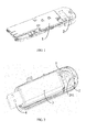
- FIG. 1 A general layout of an antenna in a conventional mobile broadband product is as shown in FIG. 1 .
- an antenna 2 is individually set on an end of a casing of the mobile broadband product, and is set in parallel to a PCBA in the casing of the mobile broadband product, so that the antenna 2 is not shielded by a PCBA 1, thus protecting the performance of the antenna. Because the antenna individually occupies a considerably large part of space, the volume of the mobile broadband products with this structure cannot be reduced, which affects the portability.
- Embodiments of the present invention provide a mobile broadband device, so as to enable a mobile broadband device to have a small volume and good portability without affecting performance of an antenna.
- An embodiment of the present invention provides a mobile broadband device, including a casing, a PCBA, and an antenna.
- the antenna and the PCBA are set in the casing, and the PCBA can be slidably pulled out or retracted back along the casing.
- the antenna is fixedly set on an inner side of the casing and forms a hollow space for accommodating the retracted PCBA.
- An embodiment of the present invention further provides a mobile broadband device, including a casing, a PCBA, and an antenna.
- the antenna and the PCBA are both set inside a cavity of the casing, and the PCBA is slidably connected to the casing.
- An interface component is fixed at an end of the PCBA, an interface hole is opened at an end of the casing, and the interface component and the interface hole are located at a same end of the mobile broadband device.
- the antenna is fixedly set on an end of the casing, and the antenna and the interface hole are respectively at two opposite ends of the casing.
- There is a contact point set on the antenna there is a feed point set on the PCBA, and the contact point of the antenna is electrically connected to the feed point of the PCBA.
- the cavity of the casing is configured to accommodate the PCBA and electrical components set on the PCBA, and a shape of the cavity of the casing matches a shape of the PCBA; when the PCBA slides along the casing, the interface component can extend out of the interface hole or be retracted back into the cavity of the casing, where the electrical components include the interface component.
- the antenna is set on an inner wall of the casing and forms a hollow space for accommodating the retracted PCBA, so that when the mobile broadband product is in a non-use state, a part of the PCBA retracted back into the casing can be placed in the hollow space of the antenna.
- the antenna does not individually occupy a part of space in the casing, and the volume of the mobile broadband device is effectively reduced.
- a part of the PCBA is pulled out from the casing while in use, so that the PCBA is pulled out from the hollow space of the antenna.
- the performance of the antenna in the casing is not affected in use.
- FIG. 1 is a schematic structural diagram of a mobile broadband product in the prior art
- FIG. 2 is a schematic structural diagram of a mobile broadband device according to an embodiment of the present invention.
- FIG. 3 is a schematic diagram of a mobile broadband device in a non-use state according to an embodiment of the present invention
- FIG. 4 is a schematic diagram of installation of an antenna of a mobile broadband device according to an embodiment of the present invention.
- FIG. 5 is a schematic diagram of connection of a PCBA and an antenna of a mobile broadband device according to an embodiment of the present invention.
- the mobile broadband device includes:
- the antenna 2 and the PCBA 3 are both set in the casing 1, the PCBA 3 includes a Printed Cirruit Board (PCB) and various electrical components set on the PCB, the various electrical components on the PCBA 3 are connected to form a hardware structure for realizing the mobile broadband connection, the PCBA 3 can be slidably pulled out or retracted back along the casing 1; the antenna 2 is fixedly set on an inner side of the casing 1 and forms a hollow space 201 for accommodating the retracted PCBA 3, there is a contact point 223 set on the antenna 2 (referring to FIG. 4 ), and the contact point 223 is electrically connected to a feed point 31 (referring to FIG. 5 ) of the PCBA 3.
- PCB Printed Cirruit Board
- the antenna 2 may be a flexible antenna or a metal antenna, specifically, a side of the antenna is closely adhered to and is fixedly set on a top end of the inner wall of the casing, and a top end of the antenna is set on a top end of the casing in a surrounding manner to form a hollow space.
- FIG. 4 shows an example of the structure of the antenna.
- a side of the antenna has a flat structure 221
- a top end of the antenna has a strip structure 222
- the flat structure 221 is closely adhered to and is set on an inner wall at the top end of the casing 1
- the flat structure 221 is electrically connected to the strip structure 222
- the strip structure 222 is set on the top end of the casing 1
- the strip structure 222 has an arc shape and forms a hollow space 201.
- a side of the antenna may have a shape that is set according to the internal form of the casing and can be closely adhered to the inner wall of the casing for the convenience of being fixed in the casing, rather than a flat structure 221; similarly, the top end of the antenna may have a shape that the top end of the antenna is perpendicular to or approximately perpendicular to the inner part that fixes the top end of the antenna inside the casing for the convenience of forming a hollow space, rather than a strip structure 222. Therefore, according to the embodiment of the present invention, the structure of the antenna may have various forms, as long as the antenna is fixedly set in the casing, does not individually occupy the space, and forms a hollow space for accommodating the retracted PCBA.
- the contact point 223 of the antenna 2 may be an elastic metal body, and the elastic metal body is slidably connected to the feed point 31 of the PCBA 3 in an elastic manner.
- there may be a limiting clamp set on the casing there may also be a positioning clamp set on the PCBA, and the positioning clamp on the PCBA corresponds to the limiting clamp on the casing. In this way, when the PCBA is slidably pulled out or retracted back, the limiting clamp on the casing may ensure that the PCBA slides in a certain range, thus well maintaining the electrical connection of the feed point 31 of the PCBA 3 and the contact point 223 of the antenna 2.
- the antenna is closely adhered to and is fixedly set on the inner side of the casing, and the antenna forms a hollow space, so that when the mobile broadband device is in a non-use state, the PCBA may be retracted back into the hollow space of the antenna, thus effectively reducing the volume and shortening the length of the entire mobile broadband device; when the mobile broadband device is in a use state, the PCBA may be slidably pulled out from the casing, so that the PCBA is pulled out from the hollow space formed by the antenna in the casing. At this time, the contact point of the antenna and the feed point of the PCBA are in electrical conduction, so that the performance of the antenna is not affected in use.
- the mobile broadband device may be a wireless modem, such as a USB data card. As shown in FIG. 2 and FIG. 3 , the mobile broadband device includes:
- the casing may be a cuboid or have a strip shape similar to a cuboid, the casing may include two or more shells, and the two or more shells are connected to each other to form a cavity; the antenna 2 and the PCBA 3 are both set in the cavity of the casing 1, the PCBA 3 is slidably connected to the casing, and the antenna 2 is fixed on an inner wall of the cavity of the casing 1.
- the PCBA 3 includes a PCB and various electrical components set on the PCB, such as a USB interface 4, an electromagnetic shield 5, and a processor; the various electrical components on the PCBA 3 are connected to form a hardware structure for realizing the mobile broadband connection, the USB interface 4 is set on an end of the PCBA 3, the casing has an interface hole opened on a position corresponding to the USB interface 4, the interface hole is located at an end of the casing 1, the USB interface 4 and the interface hole are located at a same end of the mobile broadband device; the PCBA 3 is capable of sliding along the casing 1, and when the PCBA 3 slides along the casing 1, the USB interface 4 can extend out of the interface hole or be retracted back into the cavity of the casing 1.
- various electrical components on the PCBA 3 are connected to form a hardware structure for realizing the mobile broadband connection
- the USB interface 4 is set on an end of the PCBA 3
- the casing has an interface hole opened on a position corresponding to the USB interface 4, the interface hole is located at an end of the casing 1, the USB
- the antenna 2 and the interface hole are set on two opposite ends of the casing 1 respectively, a shape of the antenna 2 matches a shape of an inner wall of the cavity of the casing 1, there is a contact point 223 (referring to FIG. 4 ) set on the antenna 2, and the contact point 223 is electrically connected to a feed point 31 (referring to FIG. 5 ) of the PCBA 3.
- the USB interface 4 when the USB interface 4 is retracted back into the cavity of the casing 1, as shown in FIG. 3 , the PCBA 3 is placed in the cavity of the casing 1, at this time, in at least one projection direction perpendicular to a sliding direction of the PCBA 3, the projection of the PCBA 3 on the inner wall of the cavity of the casing 1 partially or completely coincides with the projection of the antenna 2 on the inner wall of the cavity of the casing 1.
- the USB interface 4 extends out of the interface hole, as shown in FIG.
- the PCBA 3 vacates a part of the space 201 in the cavity at the end where the antenna 2 in the casing 1 is located, at this time, on the foregoing projection direction, the projection of the antenna 2 mostly or completely does not coincide with the projection of the PCBA 3, and the USB interface 4 extending out of the interface hole may be inserted into a USB interface slot of a computer, and the mobile broadband device may perform data transmission with the computer through the USB interface 4.
- the antenna 2 may be a flexible antenna or a metal antenna.
- the antenna 2 may include at least two parts, for example, a first part of the antenna is closely adhered to and is fixedly set on a side surface of the inner wall of the cavity at an end portion of the casing, a second part of the antenna is set on an end surface of the inner wall of the cavity at the end portion of the casing in a surrounding manner, and the second part forms a hollow space, or the first part and the second part together form a hollow space.
- FIG. 4 shows an example of the structure of the antenna.
- a first part of the antenna 2 has a flat structure 221
- a second part of the antenna 2 has a strip structure 222
- the flat structure 221 is closely adhered to and is set on a side surface of an inner wall at an end portion of the casing 1
- the flat structure 221 is electrically connected to the strip structure 222
- the strip structure 222 is set on an end surface of the inner wall of the cavity at an end portion of the casing 1
- the strip structure 222 has an arc shape and forms a hollow space 201 together with the flat structure 221.
- FIG. 4 is an example of the structure of the antenna.
- the first part of the antenna may have a shape that is set according to the internal form of the casing and can be closely adhered to the side surface of the inner wall of the casing for the convenience of being fixed in the casing, rather than a flat structure 221
- the second part of the antenna may have a shape that is set according to the internal form of the casing and can be closely adhered to the end surface of the inner wall of the casing for the convenience of being fixed in the casing, rather than a strip structure 222.
- the structure of the antenna may have various forms, as long as the antenna is fixedly set in the casing, and the shape of the antenna is adaptive to the shape of the inner wall of the cavity of the casing, at this time, the antenna does not individually occupy the space, and forms a hollow space for accommodating the retracted PCBA.
- the end portion of the casing refers to a top surface of the cuboid or strip casing and a part of the side surfaces close to and around the top;
- the side surface of the inner wall of the end portion of the casing refers to the inner wall of a part of the side surfaces of the end portion of the casing,
- the end surface of the inner wall of the end portion of the casing refers to the inner wall of the top surface of the end portion of the casing.
- the contact point 223 of the antenna 2 may be an elastic metal body, and the elastic metal body is slidably connected to the feed point 31 of the PCBA 3 in an elastic manner.
- there may be a limiting clamp set on the casing there may also be a positioning clamp set on the PCBA, and the positioning clamp on the PCBA corresponds to the limiting clamp on the casing. In this way, when the PCBA is slidably pulled out or retracted back, the limiting clamp on the casing may ensure that the PCBA slides in a certain range, thus well maintaining the electrical connection of the feed point 31 of the PCBA 3 and the contact point 223 of the antenna 2.
- the antenna is closely adhered to and is fixedly set on the inner wall of the casing, and the antenna forms a hollow space, so that when the mobile broadband device is in a non-use state, the PCBA may be retracted back into the hollow space of the antenna, thus effectively reducing the volume and shortening the length of the entire mobile broadband device; when the mobile broadband device is in a use state, the USB interface set on the PCBA may be slidably pulled out from the casing, so that the PCBA is pulled out from the hollow space formed by the antenna in the casing. At this time, the contact point of the antenna and the feed point of the PCBA are in electrical conduction, so that the performance of the antenna is not affected in use.
- the antenna is set on the inner side of the casing and forms a hollow space, so that when the mobile broadband device is in a non-use state, the PCBA may be retracted back into the hollow space of the antenna, the length of the entire mobile broadband device is shortened by about 10mm, so that the volume of the mobile broadband product is greatly reduced and the portability is significantly improved.
Landscapes
- Engineering & Computer Science (AREA)
- Computer Networks & Wireless Communication (AREA)
- Computer Hardware Design (AREA)
- General Engineering & Computer Science (AREA)
- Support Of Aerials (AREA)
- Telephone Set Structure (AREA)
- Transceivers (AREA)
Priority Applications (1)
| Application Number | Priority Date | Filing Date | Title |
|---|---|---|---|
| EP12167860.1A EP2493013A3 (de) | 2009-10-26 | 2010-10-26 | Mobile Breitbandvorrichtung |
Applications Claiming Priority (2)
| Application Number | Priority Date | Filing Date | Title |
|---|---|---|---|
| CN2009202462762U CN201549585U (zh) | 2009-10-26 | 2009-10-26 | 移动宽带装置 |
| PCT/CN2010/078100 WO2011050707A1 (zh) | 2009-10-26 | 2010-10-26 | 移动宽带装置 |
Related Child Applications (2)
| Application Number | Title | Priority Date | Filing Date |
|---|---|---|---|
| EP12167860.1A Division EP2493013A3 (de) | 2009-10-26 | 2010-10-26 | Mobile Breitbandvorrichtung |
| EP12167860.1 Division-Into | 2012-05-14 |
Publications (2)
| Publication Number | Publication Date |
|---|---|
| EP2487752A1 true EP2487752A1 (de) | 2012-08-15 |
| EP2487752A4 EP2487752A4 (de) | 2013-12-11 |
Family
ID=42604765
Family Applications (2)
| Application Number | Title | Priority Date | Filing Date |
|---|---|---|---|
| EP12167860.1A Ceased EP2493013A3 (de) | 2009-10-26 | 2010-10-26 | Mobile Breitbandvorrichtung |
| EP10826070.4A Ceased EP2487752A4 (de) | 2009-10-26 | 2010-10-26 | Mobile breitbandvorrichtung |
Family Applications Before (1)
| Application Number | Title | Priority Date | Filing Date |
|---|---|---|---|
| EP12167860.1A Ceased EP2493013A3 (de) | 2009-10-26 | 2010-10-26 | Mobile Breitbandvorrichtung |
Country Status (5)
| Country | Link |
|---|---|
| US (1) | US9013357B2 (de) |
| EP (2) | EP2493013A3 (de) |
| JP (1) | JP5495146B2 (de) |
| CN (1) | CN201549585U (de) |
| WO (1) | WO2011050707A1 (de) |
Families Citing this family (4)
| Publication number | Priority date | Publication date | Assignee | Title |
|---|---|---|---|---|
| CN201549585U (zh) | 2009-10-26 | 2010-08-11 | 华为终端有限公司 | 移动宽带装置 |
| US20140029215A1 (en) * | 2012-07-27 | 2014-01-30 | Logitech Europe S.A. | Wireless communications apparatus |
| TWI590525B (zh) * | 2013-06-04 | 2017-07-01 | 群邁通訊股份有限公司 | 天線結構及應用該天線結構的無線通訊裝置 |
| TWI814064B (zh) * | 2021-08-23 | 2023-09-01 | 群光電子股份有限公司 | 天線裝置 |
Family Cites Families (21)
| Publication number | Priority date | Publication date | Assignee | Title |
|---|---|---|---|---|
| JPH03146612A (ja) | 1989-10-30 | 1991-06-21 | Sumitomo Metal Ind Ltd | 溶銑の製造装置及び製造方法 |
| JP3146612B2 (ja) | 1992-04-14 | 2001-03-19 | 松下電器産業株式会社 | 固溶体薄膜の製造方法および太陽電池の製造方法 |
| US6031505A (en) * | 1998-06-26 | 2000-02-29 | Research In Motion Limited | Dual embedded antenna for an RF data communications device |
| FI19992267A7 (fi) * | 1999-10-20 | 2001-06-11 | Nokia Mobile Phones Ltd | Laajennuskortti langatonta tiedonsiirtoa varten ja sen antennirakenne |
| DE10038287A1 (de) * | 2000-08-05 | 2002-02-21 | Itt Mfg Enterprises Inc | Steckkarte für elektronische Geräte |
| DE60200738T2 (de) * | 2001-05-25 | 2005-07-21 | Nokia Corp. | Antenne für mobiles Telefon |
| SE0104348D0 (sv) * | 2001-12-20 | 2001-12-20 | Moteco Ab | Antennanordning |
| CN2544422Y (zh) * | 2002-05-27 | 2003-04-09 | 辜银财 | 网卡天线改良结构 |
| CN2554877Y (zh) * | 2002-05-28 | 2003-06-04 | 宇太网讯股份有限公司 | Usb无线区域网路卡 |
| DE20208802U1 (de) * | 2002-06-06 | 2002-09-05 | Gu, Yin-Tsair, Hsin Tien, Taipeh | Netzkarte für Notebook-Computer zur drahtlosen Verbindung mit einem LAN-System |
| US7632113B2 (en) * | 2003-11-17 | 2009-12-15 | Dpd Patent Trust Ltd. | Retractable USB stick |
| JP2005217190A (ja) * | 2004-01-29 | 2005-08-11 | Sdk Kk | プラグ付き電子機器収納ケース及びプラグ付き電子機器 |
| US7868832B2 (en) * | 2004-06-10 | 2011-01-11 | Galtronics Corporation Ltd. | Three dimensional antennas formed using wet conductive materials and methods for production |
| US20060284770A1 (en) * | 2005-06-15 | 2006-12-21 | Young-Min Jo | Compact dual band antenna having common elements and common feed |
| US7696931B2 (en) * | 2005-11-24 | 2010-04-13 | Lg Electronics, Inc. | Antenna for enhancing bandwidth and electronic device having the same |
| JP2007165965A (ja) * | 2005-12-09 | 2007-06-28 | Matsushita Electric Ind Co Ltd | アンテナ |
| KR101332544B1 (ko) * | 2007-01-09 | 2013-11-22 | 엘지전자 주식회사 | 휴대 단말기 |
| GB2449910B (en) * | 2007-06-07 | 2009-08-26 | Cameo Comm Inc | Antenna and wireless network device having the same |
| CN101425617B (zh) * | 2007-10-29 | 2012-11-14 | 英业达股份有限公司 | 具有伸缩式天线的电子装置 |
| CN101459706B (zh) * | 2008-12-23 | 2011-06-15 | 华为终端有限公司 | 无线终端以及无线终端的加工方法 |
| CN201549585U (zh) | 2009-10-26 | 2010-08-11 | 华为终端有限公司 | 移动宽带装置 |
-
2009
- 2009-10-26 CN CN2009202462762U patent/CN201549585U/zh not_active Expired - Lifetime
-
2010
- 2010-10-26 EP EP12167860.1A patent/EP2493013A3/de not_active Ceased
- 2010-10-26 EP EP10826070.4A patent/EP2487752A4/de not_active Ceased
- 2010-10-26 JP JP2012535610A patent/JP5495146B2/ja active Active
- 2010-10-26 WO PCT/CN2010/078100 patent/WO2011050707A1/zh not_active Ceased
-
2012
- 2012-04-25 US US13/455,262 patent/US9013357B2/en active Active
Also Published As
| Publication number | Publication date |
|---|---|
| JP2013509119A (ja) | 2013-03-07 |
| WO2011050707A1 (zh) | 2011-05-05 |
| US9013357B2 (en) | 2015-04-21 |
| US20120212377A1 (en) | 2012-08-23 |
| EP2493013A3 (de) | 2014-04-09 |
| CN201549585U (zh) | 2010-08-11 |
| EP2493013A2 (de) | 2012-08-29 |
| JP5495146B2 (ja) | 2014-05-21 |
| EP2487752A4 (de) | 2013-12-11 |
Similar Documents
| Publication | Publication Date | Title |
|---|---|---|
| US6292148B1 (en) | Radio communication terminal | |
| US20100279694A1 (en) | Display panel structure, electronic device using the same, and mobile information equipment | |
| EP2833233A1 (de) | Intelligentes endgerät mit austausch einer drahtlosen kommunikationsvorrichtung durch einen benutzer | |
| CN105340129B (zh) | 具有新型天线结构的移动终端 | |
| EP2595253A1 (de) | Usb-stecker, damit verbundene bestückte leiterplatte und usb-vorrichtung | |
| JP6243011B2 (ja) | 端末装置 | |
| US9013357B2 (en) | Mobile broadband device | |
| EP2328241B1 (de) | Drehstecker für Datenkarte | |
| CN105932397A (zh) | 一种天线装置及通信设备 | |
| US20130321219A1 (en) | Antenna in electronic device with separable radiator | |
| US8843185B2 (en) | Slide-type wireless terminal apparatus | |
| EP2793316B1 (de) | USB-Gerät mit Spannmittel | |
| CN206098950U (zh) | 一种电子设备 | |
| US20130058058A1 (en) | Usb plug and usb modem | |
| US20070212938A1 (en) | Connection cable between printed circuit boards of a portable terminal | |
| EP3046183A1 (de) | Usb-kommunikationsendgerät | |
| KR102456215B1 (ko) | 고속 커넥터를 위한 접지 | |
| CN102983875B (zh) | 一种降低对数据卡天线灵敏度干扰的方法及设备 | |
| CN201527666U (zh) | 一种用户身份识别卡屏蔽装置 | |
| EP2584648A1 (de) | Mobiles Funkendgerät | |
| CN205213255U (zh) | 一种移动终端的屏蔽罩及移动终端 | |
| TWI282194B (en) | FPC connector with metal shielding for preventing from EMI | |
| JP2010119002A (ja) | 携帯端末装置 | |
| US20250175549A1 (en) | Electronic apparatus | |
| US20130207871A1 (en) | Compact multi-band antenna with integrating fed through co-axial cable |
Legal Events
| Date | Code | Title | Description |
|---|---|---|---|
| PUAI | Public reference made under article 153(3) epc to a published international application that has entered the european phase |
Free format text: ORIGINAL CODE: 0009012 |
|
| 17P | Request for examination filed |
Effective date: 20120508 |
|
| AK | Designated contracting states |
Kind code of ref document: A1 Designated state(s): AL AT BE BG CH CY CZ DE DK EE ES FI FR GB GR HR HU IE IS IT LI LT LU LV MC MK MT NL NO PL PT RO RS SE SI SK SM TR |
|
| DAX | Request for extension of the european patent (deleted) | ||
| A4 | Supplementary search report drawn up and despatched |
Effective date: 20131107 |
|
| RIC1 | Information provided on ipc code assigned before grant |
Ipc: H01Q 5/00 20060101ALI20131101BHEP Ipc: H01Q 1/22 20060101AFI20131101BHEP Ipc: H01Q 1/24 20060101ALI20131101BHEP Ipc: H01Q 9/42 20060101ALI20131101BHEP |
|
| 17Q | First examination report despatched |
Effective date: 20151023 |
|
| REG | Reference to a national code |
Ref country code: DE Ref legal event code: R003 |
|
| STAA | Information on the status of an ep patent application or granted ep patent |
Free format text: STATUS: THE APPLICATION HAS BEEN REFUSED |
|
| 18R | Application refused |
Effective date: 20161208 |