EP2487473A1 - Device for trapping fuel vapours in the gauge of a set of gauges of a device for distributing liquid fuel during said gauge - Google Patents
Device for trapping fuel vapours in the gauge of a set of gauges of a device for distributing liquid fuel during said gauge Download PDFInfo
- Publication number
- EP2487473A1 EP2487473A1 EP12153761A EP12153761A EP2487473A1 EP 2487473 A1 EP2487473 A1 EP 2487473A1 EP 12153761 A EP12153761 A EP 12153761A EP 12153761 A EP12153761 A EP 12153761A EP 2487473 A1 EP2487473 A1 EP 2487473A1
- Authority
- EP
- European Patent Office
- Prior art keywords
- gauge
- fuel
- emptying
- gauging
- neck
- Prior art date
- Legal status (The legal status is an assumption and is not a legal conclusion. Google has not performed a legal analysis and makes no representation as to the accuracy of the status listed.)
- Granted
Links
- 239000000446 fuel Substances 0.000 title claims abstract description 80
- 239000007788 liquid Substances 0.000 title claims abstract description 14
- 239000011521 glass Substances 0.000 claims abstract description 15
- 230000008020 evaporation Effects 0.000 claims abstract description 4
- 238000001704 evaporation Methods 0.000 claims abstract description 4
- 238000005259 measurement Methods 0.000 claims description 10
- 238000003780 insertion Methods 0.000 claims description 3
- 230000037431 insertion Effects 0.000 claims description 3
- 239000012071 phase Substances 0.000 description 9
- 238000000034 method Methods 0.000 description 5
- 239000000203 mixture Substances 0.000 description 3
- 230000000712 assembly Effects 0.000 description 2
- 238000000429 assembly Methods 0.000 description 2
- 239000010763 heavy fuel oil Substances 0.000 description 2
- 229920006395 saturated elastomer Polymers 0.000 description 2
- 239000010409 thin film Substances 0.000 description 2
- 239000012808 vapor phase Substances 0.000 description 2
- 238000009736 wetting Methods 0.000 description 2
- 125000004122 cyclic group Chemical group 0.000 description 1
- 238000010586 diagram Methods 0.000 description 1
- 239000002283 diesel fuel Substances 0.000 description 1
- 239000007791 liquid phase Substances 0.000 description 1
- 238000012423 maintenance Methods 0.000 description 1
- 239000002184 metal Substances 0.000 description 1
- 238000007789 sealing Methods 0.000 description 1
Images


Classifications
-
- B—PERFORMING OPERATIONS; TRANSPORTING
- B67—OPENING, CLOSING OR CLEANING BOTTLES, JARS OR SIMILAR CONTAINERS; LIQUID HANDLING
- B67D—DISPENSING, DELIVERING OR TRANSFERRING LIQUIDS, NOT OTHERWISE PROVIDED FOR
- B67D7/00—Apparatus or devices for transferring liquids from bulk storage containers or reservoirs into vehicles or into portable containers, e.g. for retail sale purposes
- B67D7/06—Details or accessories
- B67D7/08—Arrangements of devices for controlling, indicating, metering or registering quantity or price of liquid transferred
- B67D7/085—Testing or calibrating apparatus therefore
-
- G—PHYSICS
- G01—MEASURING; TESTING
- G01F—MEASURING VOLUME, VOLUME FLOW, MASS FLOW OR LIQUID LEVEL; METERING BY VOLUME
- G01F25/00—Testing or calibration of apparatus for measuring volume, volume flow or liquid level or for metering by volume
- G01F25/0092—Testing or calibration of apparatus for measuring volume, volume flow or liquid level or for metering by volume for metering by volume
-
- G—PHYSICS
- G01—MEASURING; TESTING
- G01F—MEASURING VOLUME, VOLUME FLOW, MASS FLOW OR LIQUID LEVEL; METERING BY VOLUME
- G01F25/00—Testing or calibration of apparatus for measuring volume, volume flow or liquid level or for metering by volume
- G01F25/10—Testing or calibration of apparatus for measuring volume, volume flow or liquid level or for metering by volume of flowmeters
- G01F25/17—Testing or calibration of apparatus for measuring volume, volume flow or liquid level or for metering by volume of flowmeters using calibrated reservoirs
Definitions
- the present invention relates to a device for trapping fuel vapors in the gauge of a gauging assembly of a liquid fuel dispensing device of a service station during the emptying of the dipstick.
- Such a fuel dispensing device is conventionally connected on the one hand to a fuel distribution circuit connected to a storage tank and, on the other hand, equipped with a volumetric meter, generally as a piston meter with adjustable stroke. cooperating with a display, and a flexible fuel supply hose connected to a dispensing gun with a nozzle.
- gauging assemblies are used essentially comprising a gauge generally of metal comprising a predefined volume gauge body equipped with an outlet opening that can be closed by a gauge emptying valve. , as well as a gauge neck equipped with a scale and wherein the tip of the dispensing gun can be inserted to allow filling the fuel gauge.
- the volume thus introduced into the gauge is then read on this graduation and this volume read is compared with the volume displayed on the dispensing apparatus.
- actuation means of the volumetric measurer (serrated wheels which make it possible to adjust the stroke of the pistons in the case of a piston volumetric measurer) which make it possible to adjust the cyclic volume of the measuring device equipping the dispensing device so as to obtain the equality of these volumes.
- the gauge is emptied into a fuel collection tank which can be constituted by the storage tank of the service station or by an independent reservoir, this being connected to the outlet opening of the gauge body, a generally flexible drain line connected to this collection tank and opening the gauge emptying valve.
- a fuel collection tank which can be constituted by the storage tank of the service station or by an independent reservoir, this being connected to the outlet opening of the gauge body, a generally flexible drain line connected to this collection tank and opening the gauge emptying valve.
- Such a difference in temperature which may be of the order of 20 ° C, especially in summer, may indeed lead to expansion phenomena or retraction of the gauge likely to distort the measurements.
- the amount of fuel thus measured is not the same if after carrying out the preceding operation, the gauge emptying valve was closed as soon as the last drop of fuel had been removed or if it had been planned previously. a period of dewatering time to dry the gauge.
- the gauging assembly For this purpose, it is necessary to equip the gauging assembly with a sight glass connected to the outlet opening of the gauge body and to mount the emptying pipe connected to the fuel collecting tank at the outlet of this glass. sight, viewer.
- the fuel flows first continuously and then drip.
- the viewfinder glass makes it possible to observe the beginning of this drip flow according to the continuous flow.
- the first of these sources of losses is related to the fact that the atmospheric pressure is lower than the saturation vapor pressure of the fuel, that is to say the equilibrium pressure between the liquid phase fuel and the fuel in vapor phase.
- the inner portion of the gauge is initially filled with air at atmospheric pressure.
- the amount of air discharged to the outside when the gauge is filled by the gap between the tip of the dispensing nozzle and the walls of the gauge neck (which corresponds to the volume of spilled fuel), necessarily contains a significant proportion of vapor phase fuel.
- the second source of fuel loss is related to the fact that, during each gauging operation, it occurs around the jet of fuel coming out of the tip of the dispensing gun, a misting may cause droplets of a nature to evaporate or to be evacuated out of the gauge with the air discharged during filling, by the clearance between the walls of the gauge neck and the dispensing gun.
- the object of the present invention is to remedy this drawback by proposing a device for trapping fuel vapors in the gauge of a gauging assembly of a liquid fuel dispensing apparatus of the aforementioned type when this gauge is emptied.
- such a device is characterized in that it comprises a square or rounded U-shaped rigid pipe section, forming a siphon connected to the emptying pipe so as to block the passage of the fuel vapors towards the tank fuel collection.
- This section of siphon pipe thus comprises two lateral branches surrounding a central branch, low located at a lower level than the sight glass and the emptying pipe.
- Such a section of pipe is preferably mounted directly at the exit of the sight glass.
- the central branch and the lower part of the lateral branches of the siphon pipe section are filled with fuel.
- the central branch and the lower part of the lateral branches of this section of pipe are always filled with fuel to block the passage of vapors from the gauge, which ensures that it is actually filled with fuel vapors during the next gauging operation.
- the emptying pipe and the siphon pipe section are preferably removable.
- the siphon pipe section and the emptying pipe can thus be disassembled so as to completely empty this section of the residual fuel.
- the gauge is then completely saturated with fuel vapors and is ready for the next gauging operation.
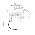
- the gauging assembly comprises a gauge 1 of predefined capacity comprising a gauge body 4 and a gauge neck 12 provided with an inlet opening 13.
- This inlet opening 13 is intended to receive the tip 15 of the dispensing gun 14 mounted at the end of the flexible hose 16 for supplying liquid fuel to a dispensing device to be gauged so as to allow the filling of the dipstick. 1 with liquid fuel 3.
- the gauge body 4 is equipped at its lower part with an outlet opening 5 which can be closed by a manual dip valve 6.
- the gauge neck 12 is, meanwhile, equipped with a transparent graduation 17 allowing a maintenance technician to read the volume of liquid fuel 3 spilled during a gauging.
- a connector element 18 is mounted at the free end of this gauge neck 12 so as to ensure the seal between the atmosphere and the internal portion of the gauge 1, in particular after insertion of the tip 15 of the gun. distributor 14.
- Balancing means 2 schematically dashed to avoid evaporation of the fuel 3 dumped in the gauge 1 so as to constantly maintain the internal portion thereof, the saturation vapor saturation pressure of the fuel under the conditions temperature and pressure applicable to the measurement.
- the gauge 11 is constantly filled with fuel vapors and not with a mixture of fuel vapors / air.
- a sight glass 7 whose function is to enable the emptying procedure of the gauge 1 to be carried out in accordance with the requirements of legal metrology, is connected to the outlet opening 5 of the gauge body 4.
- a U-shaped rigid pipe section 10 having two lateral branches 20 surrounding a low central branch 19 is mounted directly at the outlet of the sight glass 7.
- the two lateral branches 20 are substantially vertical and the low central branch 19 is substantially horizontal.
- a discharge pipe 9 connected to a fuel collection tank 8 is mounted at the outlet of the siphon pipe section 10.
- the emptying pipe 9 may be flexible or rigid.
- the emptying pipe 9 and the siphon pipe section 10 are removable from the gauging assembly.
- the emptying procedure is carried out in two phases, namely a first phase during which the liquid fuel 3 flows in a continuous flow into the sight glass 7, the pipe section 10 and the pipe emptying 9 to the collection tank 8, and a second phase or dewatering phase preceding the closure of the gauge emptying valve 6 during which the fuel 3 drips.
- the fuel vapors present in the 11 gauge sky which are heavier than air, can not exit the gauge body 4.
- the inner part of the gauge 1 contains only fuel vapors and not a mixture of fuel vapors / air.
- the siphon pipe section 10 can be disassembled and then completely emptied of the residual fuel.
- the gauge body 4 is then completely saturated with fuel vapors and the gauge 1 is ready for the next gauging operation.
Landscapes
- Physics & Mathematics (AREA)
- Fluid Mechanics (AREA)
- General Physics & Mathematics (AREA)
- Engineering & Computer Science (AREA)
- Mathematical Physics (AREA)
- Theoretical Computer Science (AREA)
- Mechanical Engineering (AREA)
- Loading And Unloading Of Fuel Tanks Or Ships (AREA)
- Filling Or Discharging Of Gas Storage Vessels (AREA)
Abstract
Description
La présente invention a pour objet un dispositif de piégeage des vapeurs de carburant dans la jauge d'un ensemble de jaugeage d'un appareil distributeur de carburant liquide d'une station service lors du vidage de cette jauge.The present invention relates to a device for trapping fuel vapors in the gauge of a gauging assembly of a liquid fuel dispensing device of a service station during the emptying of the dipstick.
Un tel appareil distributeur de carburant est classiquement d'une part branché sur un circuit de distribution de carburant relié à une cuve de stockage et d'autre part équipé d'un mesureur volumétrique, en règle générale d'un mesureur à pistons à course réglable coopérant avec un afficheur, ainsi que d'un tuyau flexible d'alimentation en carburant relié à un pistolet distributeur muni d'un embout.Such a fuel dispensing device is conventionally connected on the one hand to a fuel distribution circuit connected to a storage tank and, on the other hand, equipped with a volumetric meter, generally as a piston meter with adjustable stroke. cooperating with a display, and a flexible fuel supply hose connected to a dispensing gun with a nozzle.
Ces appareils distributeurs de carburant doivent être soumis régulièrement à des opérations de jaugeage pour satisfaire aux exigences de la métrologie légale.These fuel dispensing devices must be regularly subjected to gauging operations to meet the requirements of legal metrology.
Pour la mise en oeuvre de ces opérations de jaugeage, on utilise des ensembles de jaugeage comportant essentiellement une jauge en règle générale métallique comprenant un corps de jauge de volume prédéfini équipé d'une ouverture de sortie pouvant être fermée par une vanne de vidage de jauge, ainsi qu'un col de jauge équipé d'une graduation et dans lequel l'embout du pistolet distributeur peut être inséré pour permettre de remplir la jauge de carburant.For the implementation of these gauging operations, gauging assemblies are used essentially comprising a gauge generally of metal comprising a predefined volume gauge body equipped with an outlet opening that can be closed by a gauge emptying valve. , as well as a gauge neck equipped with a scale and wherein the tip of the dispensing gun can be inserted to allow filling the fuel gauge.
Lors d'une opération de jaugeage, on insère l'embout du pistolet distributeur dans le col de jauge et on verse du carburant dans la jauge jusqu'à la graduation située sur le col de celle-ci.During a gauging operation, insert the tip of the dispensing gun in the gauge neck and pour fuel into the gauge to the graduation on the neck of it.
On lit ensuite le volume ainsi introduit dans la jauge sur cette graduation et on compare ce volume lu au volume affiché sur l'appareil distributeur.The volume thus introduced into the gauge is then read on this graduation and this volume read is compared with the volume displayed on the dispensing apparatus.
En cas de différence entre ces deux volumes, on actionne des moyens d'ajustement du mesureur volumétrique (des roues dentelées qui permettent de régler la course des pistons dans le cas d'un mesureur volumétrique à pistons) qui permettent de régler le volume cyclique du mesureur équipant l'appareil distributeur de façon à obtenir l'égalité de ces volumes.If there is a difference between these two volumes, actuation means of the volumetric measurer (serrated wheels which make it possible to adjust the stroke of the pistons in the case of a piston volumetric measurer) which make it possible to adjust the cyclic volume of the measuring device equipping the dispensing device so as to obtain the equality of these volumes.
Après avoir effectué cette mesure, on vide la jauge dans un réservoir de collecte du carburant qui peut être constitué par la cuve de stockage de la station service ou par un réservoir indépendant, ce en branchant sur l'ouverture de sortie du corps de jauge, une canalisation de vidage en règle générale flexible reliée à ce réservoir de collecte et en ouvrant la vanne de vidage de jauge.After carrying out this measurement, the gauge is emptied into a fuel collection tank which can be constituted by the storage tank of the service station or by an independent reservoir, this being connected to the outlet opening of the gauge body, a generally flexible drain line connected to this collection tank and opening the gauge emptying valve.
Il est à noter que la métrologie légale impose que le jaugeage des appareils distributeurs de carburant, soit effectué avec une précision au millième.It should be noted that the legal metrology requires that the gauging of fuel dispensing devices be carried out with a precision to the thousandth.
Pour respecter cette exigence, il est nécessaire d'exclure toute erreur de mesure consécutive à des phénomènes de dilatation ou de rétraction de la jauge du fait de différences entre la température du carburant situé dans la cuve de stockage de la station service qui est en règle générale souterraine et la température de la jauge sèche qui sort notamment d'un camion de transport.To comply with this requirement, it is necessary to exclude any measurement error resulting from the expansion or retraction of the dipstick due to differences in the temperature of the fuel in the service station storage tank that is in good standing. underground temperature and the temperature of the dry gauge coming out of a transport truck.
Une telle différence de température qui peut être de l'ordre de 20°C, notamment en été, peut en effet entraîner des phénomènes de dilatation ou de rétraction de la jauge de nature à fausser les mesures.Such a difference in temperature which may be of the order of 20 ° C, especially in summer, may indeed lead to expansion phenomena or retraction of the gauge likely to distort the measurements.
Pour remédier à ce problème, avant l'opération de jaugeage proprement dite qui nécessite en règle générale la moyenne de deux ou de trois mesures, il est nécessaire d'effectuer une étape de mouillage préalable consistant à remplir la jauge au maximum puis à la vider dans le réservoir de collecte du carburant pour la mettre en température.To remedy this problem, before the actual gauging operation which generally requires the average of two or three measurements, it is necessary to carry out a preliminary wetting step of filling the gauge to the maximum and then emptying it. in the fuel collection tank to put it in temperature.
Lors de cette étape de mouillage préalable, une fine pellicule de carburant reste collée sur les parois de la jauge.During this preliminary wetting step, a thin film of fuel remains stuck on the walls of the gauge.
Or, la présence de cette fine pellicule de carburant peut être source de fluctuations du résultat obtenu lors du jaugeage ultérieur.However, the presence of this thin film of fuel can be a source of fluctuations in the result obtained during the subsequent gauging.
En effet, la quantité de carburant ainsi mesurée n'est pas la même si après avoir effectué l'opération précédente, on a fermé la vanne de vidage de jauge dès la sortie de la dernière goutte de carburant ou si l'on a prévu auparavant un laps de temps d'égouttage permettant de sécher la jauge.In fact, the amount of fuel thus measured is not the same if after carrying out the preceding operation, the gauge emptying valve was closed as soon as the last drop of fuel had been removed or if it had been planned previously. a period of dewatering time to dry the gauge.
Pour éviter les imprécisions liées à ces fluctuations des résultats de mesure, la métrologie légale impose de respecter une procédure de vidage particulière après chaque mesure.To avoid inaccuracies related to these fluctuations in measurement results, legal metrology requires that a specific emptying procedure be followed after each measurement.
A cet effet, il est nécessaire d'équiper l'ensemble de jaugeage d'un verre viseur branché sur l'ouverture de sortie du corps de jauge et de monter la canalisation de vidage reliée au réservoir de collecte du carburant en sortie de ce verre viseur.For this purpose, it is necessary to equip the gauging assembly with a sight glass connected to the outlet opening of the gauge body and to mount the emptying pipe connected to the fuel collecting tank at the outlet of this glass. sight, viewer.
Lors du vidage de la jauge le carburant s'écoule tout d'abord en flux continu puis goutte à goutte.When emptying the gauge, the fuel flows first continuously and then drip.
Le verre viseur permet d'observer le début de cet écoulement en goutte à goutte suivant le flux continu.The viewfinder glass makes it possible to observe the beginning of this drip flow according to the continuous flow.
Or dans ce contexte et pour uniformiser les résultats de mesure, la métrologie légale impose de ne fermer la vanne de vidage de jauge que 30 secondes après l'observation du début du goutte à goutte.But in this context and to standardize the measurement results, the legal metrology requires to close the gauge emptying valve only 30 seconds after the observation of the beginning of the drip.
Indépendamment de ce qui précède, on s'est rendu compte que, lors d'une opération de jaugeage classique, le volume lu sur la graduation équipant le col de jauge, est en fait inférieur au volume de carburant réellement déversé dans celle-ci du fait de pertes non négligeables consécutives au jeu existant entre l'embout du pistolet distributeur et les parois du col de jauge.Independently of the foregoing, it has been found that, during a conventional gauging operation, the volume read on the graduation equipping the gauge neck is actually lower than the volume of fuel actually poured into it. made of non-negligible losses consecutive to the clearance between the tip of the dispensing gun and the walls of the gauge neck.
Cette absence d'étanchéité à ce niveau, entraîne plus précisément deux sources de perte.This lack of sealing at this level, more precisely causes two sources of loss.
La première de ces sources de pertes, est liée au fait que la pression atmosphérique est inférieure à la pression de vapeur saturante du carburant, c'est-à-dire à la pression d'équilibre entre le carburant en phase liquide et le carburant en phase vapeur.The first of these sources of losses is related to the fact that the atmospheric pressure is lower than the saturation vapor pressure of the fuel, that is to say the equilibrium pressure between the liquid phase fuel and the fuel in vapor phase.
Lors d'une opération de jaugeage classique, la partie interne de la jauge est initialement remplie d'air se trouvant à la pression atmosphérique.During a conventional gauging operation, the inner portion of the gauge is initially filled with air at atmospheric pressure.
Au cours du remplissage, une certaine proportion du carburant liquide déversé s'évapore pour permettre de maintenir l'équilibre de pression.During filling, a certain proportion of the spilled liquid fuel evaporates to maintain the pressure balance.
Il en résulte que la quantité d'air refoulée vers l'extérieur lors du remplissage de la jauge par le jeu existant entre l'embout du pistolet distributeur et les parois du col de jauge (qui correspond au volume de carburant déversé), renferme obligatoirement une proportion non négligeable de carburant en phase vapeur.As a result, the amount of air discharged to the outside when the gauge is filled by the gap between the tip of the dispensing nozzle and the walls of the gauge neck (which corresponds to the volume of spilled fuel), necessarily contains a significant proportion of vapor phase fuel.
La seconde source de pertes de carburant est liée au fait que, lors de chaque opération de jaugeage, il se produit autour du jet de carburant sortant de l'embout du pistolet distributeur, une brumisation pouvant engendrer des gouttelettes de nature à s'évaporer ou à être évacuées hors de la jauge avec l'air refoulé lors du remplissage, par le jeu existant entre les parois du col de jauge et le pistolet distributeur.The second source of fuel loss is related to the fact that, during each gauging operation, it occurs around the jet of fuel coming out of the tip of the dispensing gun, a misting may cause droplets of a nature to evaporate or to be evacuated out of the gauge with the air discharged during filling, by the clearance between the walls of the gauge neck and the dispensing gun.
De telles pertes qui affectent principalement l'essence traditionnelle, nettement plus volatile que le carburant diesel, dépendent de divers paramètres, en particulier de la nature du carburant distribué, de la température et de la saison; elles peuvent s'élever jusqu'à 3/1000 de la quantité de carburant distribuée dans le cas d'une jauge de 20 litres, ce qui entraîne des pertes importantes pour les gérants des stations-services, du fait d'un réglage erroné des mesureurs des appareils distributeurs.Such losses, which mainly affect traditional gasoline, which is much more volatile than diesel fuel, depend on various parameters, particularly the nature of the fuel dispensed, the temperature and the season; they can be up to 3/1000 of the amount of fuel dispensed in the case of a 20-liter which leads to significant losses for the managers of the service stations, due to a wrong setting of the meters of the dispensing devices.
Pour remédier à cet inconvénient, on a préalablement eu l'idée de maintenir l'étanchéité entre l'embout du pistolet distributeur et les parois du col de jauge pendant une opération de jaugeage, et également de maintenir constamment, pendant une telle opération, la partie interne de la jauge, c'est-à-dire le ciel de jauge surmontant le carburant distribué à la pression de saturation dans les conditions de température et de pression applicables à la mesure.To overcome this drawback, it was previously thought to maintain the seal between the tip of the dispensing gun and the walls of the gauge neck during a gauging operation, and also to constantly maintain, during such an operation, the internal part of the gauge, that is to say the sky gauge overcoming the fuel dispensed to the saturation pressure under the conditions of temperature and pressure applicable to the measurement.
A cet effet, il a été proposé d'équiper les ensembles de jaugeage d'une part d'un élément connecteur monté à l'extrémité libre du col de jauge de façon à permettre de garantir l'étanchéité entre l'atmosphère et la partie interne de la jauge, en particulier après insertion de l'embout du pistolet distributeur dans le col de jauge, et d'autre part de moyens d'équilibrage permettant d'éviter l'évaporation du carburant lors d'une opération de jaugeage de façon à maintenir constamment le ciel de jauge à la pression de vapeur saturante du carburant.For this purpose, it has been proposed to equip the gauging assemblies on the one hand with a connector element mounted on the free end of the gauge neck so as to guarantee the seal between the atmosphere and the part internal of the gauge, in particular after insertion of the tip of the dispensing gun into the gauge neck, and secondly balancing means to prevent the evaporation of the fuel during a gauging operation so to constantly maintain the gauge sky at the saturation vapor pressure of the fuel.
Un ensemble de jaugeage ainsi équipé, est à titre d'exemple, décrit dans le document non publié
On s'est toutefois rendu compte, conformément à l'invention, que de tels moyens étaient insuffisants pour permettre de garantir que les vapeurs renfermées dans la jauge ne soient constamment constituées que par des vapeurs de carburant et non par un mélange vapeurs de carburant/air.However, it has been realized, in accordance with the invention, that such means are insufficient to ensure that the vapors contained in the gauge are constantly constituted only by fuel vapors and not by a mixture of fuel vapors. air.
En effet, du fait du processus de vidage particulier de la jauge, imposé par la métrologie légale, des vapeurs de carburant peuvent s'échapper par la canalisation de vidage pendant le laps de temps d'égouttage précédant la fermeture de la vanne de vidage de jauge et être remplacées par de l'air.Indeed, because of the particular emptying process of the gauge, imposed by the legal metrology, fuel vapors can escape through the emptying pipe during the dewatering time period preceding the closing of the emptying valve. gauge and be replaced by air.
La présente invention a pour objet de remédier à cet inconvénient en proposant un dispositif de piégeage des vapeurs de carburant dans la jauge d'un ensemble de jaugeage d'un appareil distributeur de carburant liquide du type susmentionné lors du vidage de cette jauge.The object of the present invention is to remedy this drawback by proposing a device for trapping fuel vapors in the gauge of a gauging assembly of a liquid fuel dispensing apparatus of the aforementioned type when this gauge is emptied.
Selon l'invention, un tel dispositif est caractérisé en ce qu'il comprend un tronçon de canalisation rigide en forme de U carré ou arrondi, formant siphon branché sur la canalisation de vidage de façon à bloquer le passage des vapeurs de carburant vers le réservoir de collecte du carburant.According to the invention, such a device is characterized in that it comprises a square or rounded U-shaped rigid pipe section, forming a siphon connected to the emptying pipe so as to block the passage of the fuel vapors towards the tank fuel collection.
Ce tronçon de canalisation formant siphon comporte ainsi deux branches latérales entourant une branche centrale, basse située à un niveau inférieur à celui du verre viseur et de la canalisation de vidage.This section of siphon pipe thus comprises two lateral branches surrounding a central branch, low located at a lower level than the sight glass and the emptying pipe.
Un tel tronçon de canalisation est, de préférence, monté directement en sortie du verre viseur.Such a section of pipe is preferably mounted directly at the exit of the sight glass.
Lors de la première phase du processus de vidage de la jauge pendant laquelle le carburant s'écoule en flux continu, la branche centrale et la partie inférieure des branches latérales du tronçon de canalisation formant siphon se remplissent de carburantDuring the first phase of the emptying process of the gauge during which the fuel flows in a continuous flow, the central branch and the lower part of the lateral branches of the siphon pipe section are filled with fuel.
Lors de la seconde phase ou phase d'égouttage précédant la fermeture de la vanne de vidage de jauge pendant laquelle le carburant s'écoule en goutte à goutte, la branche centrale et la partie inférieure des branches latérales de ce tronçon de canalisation, sont toujours remplies de carburant de façon à bloquer le passage des vapeurs provenant de la jauge, ce qui permet de garantir que celle-ci soit effectivement remplie de vapeurs de carburant lors de l'opération de jaugeage suivante.During the second phase or dewatering phase preceding the closing of the gauge emptying valve during which the fuel drips, the central branch and the lower part of the lateral branches of this section of pipe, are always filled with fuel to block the passage of vapors from the gauge, which ensures that it is actually filled with fuel vapors during the next gauging operation.
Selon l'invention, la canalisation de vidage et le tronçon de canalisation formant siphon sont de préférence amovibles.According to the invention, the emptying pipe and the siphon pipe section are preferably removable.
Après la fermeture de la vanne de vidage de jauge, le tronçon de canalisation formant siphon ainsi que la canalisation de vidage, peuvent ainsi être démontés de façon à permettre de vider complètement ce tronçon du carburant résiduel.After closure of the gauge emptying valve, the siphon pipe section and the emptying pipe can thus be disassembled so as to completely empty this section of the residual fuel.
La jauge est alors complètement saturée en vapeurs de carburant et est prête pour l'opération de jaugeage suivante.The gauge is then completely saturated with fuel vapors and is ready for the next gauging operation.
Les caractéristiques du dispositif de piégeage des vapeurs de carburant qui fait l'objet de l'invention, seront décrites plus en détail en se référant au dessin non limitatif annexé qui est un schéma représentant un ensemble de jaugeage équipé d'un tel dispositif.The characteristics of the device for trapping fuel vapors which is the subject of the invention will be described in more detail with reference to the appended nonlimiting drawing which is a diagram showing a gauging assembly equipped with such a device.
Selon la figure, l'ensemble de jaugeage comprend une jauge 1 de contenance prédéfinie comportant un corps de jauge 4 et un col de jauge 12 muni d'une ouverture d'entrée 13.According to the figure, the gauging assembly comprises a gauge 1 of predefined capacity comprising a
Cette ouverture d'entrée 13, est destinée à recevoir l'embout 15 du pistolet distributeur 14 monté à l'extrémité du tuyau flexible 16 d'alimentation en carburant liquide d'un appareil distributeur à jauger de façon à permettre le remplissage de la jauge 1 par du carburant liquide 3.This inlet opening 13, is intended to receive the
Le corps de jauge 4 est équipé à sa partie inférieure, d'une ouverture de sortie 5 pouvant être fermée par une vanne de vidage de jauge manuelle 6.The
Le col de jauge 12 est, quant à lui, équipé d'une graduation transparente 17 permettant à un technicien de maintenance de lire le volume de carburant liquide 3 déversé lors d'un jaugeage.The
Un élément connecteur 18 est monté à l'extrémité libre de ce col de jauge 12 de façon à permettre de garantir l'étanchéité entre l'atmosphère et la partie interne de la jauge 1, en particulier après insertion de l'embout 15 du pistolet distributeur 14.A connector element 18 is mounted at the free end of this
Des moyens d'équilibrage 2 schématisés en pointillés permettent d'éviter l'évaporation du carburant 3 déversé dans la jauge 1 de façon à maintenir constamment la partie interne de celle-ci, à la pression de saturation de vapeur saturante du carburant dans les conditions de température et de pression applicables à la mesure.Balancing means 2 schematically dashed to avoid evaporation of the
Par suite, le ciel de jauge 11 est constamment rempli de vapeurs de carburant et non d'un mélange vapeurs de carburant/air.As a result, the
En outre et selon la figure, un verre viseur 7 ayant pour fonction de permettre d'effectuer la procédure de vidage de la jauge 1 conformément aux prescriptions de la métrologie légale, est branché sur l'ouverture de sortie 5 du corps de jauge 4.In addition and according to the figure, a
Un tronçon de canalisation rigide en forme de U 10 comportant deux branches latérales 20 entourant une branche centrale basse 19 est monté directement en sortie du verre viseur 7.A U-shaped
Lors du vidage du carburant, les deux branches latérales 20 sont sensiblement verticales et la branche centrale basse 19 est sensiblement horizontale.When emptying the fuel, the two
Une canalisation de vidage 9 reliée à un réservoir de collecte du carburant 8, est montée en sortie du tronçon de canalisation formant siphon 10.A discharge pipe 9 connected to a
La canalisation de vidage 9 peut être flexible ou rigide.The emptying pipe 9 may be flexible or rigid.
La canalisation de vidage 9 ainsi que le tronçon de canalisation formant siphon 10, sont amovibles de l'ensemble de jaugeage.The emptying pipe 9 and the siphon
A l'issue d'une opération de jaugeage et suite à l'ouverture de la vanne de vidage de jauge 6 le carburant liquide 3 déversé dans le corps de jauge 4, est vidé par l'ouverture de sortie 5 vers le réservoir de collecte de carburant 8.After a gauging operation and following the opening of the
Lors de ce vidage, le carburant liquide 3 passe dans le verre viseur 7 puis dans le tronçon de canalisation 10 puis dans la canalisation de vidage 9.During this emptying, the
Conformément aux prescriptions de la métrologie légale, la procédure de vidage s'effectue en deux phases, à savoir une première phase pendant laquelle le carburant liquide 3 s'écoule en flux continu dans le verre viseur 7, le tronçon de canalisation 10 et la canalisation de vidage 9 jusqu'au réservoir de collecte 8, et une seconde phase ou phase d'égouttage précédant la fermeture de la vanne de vidage de jauge 6 pendant laquelle le carburant 3 s'écoule en goutte à goutte.In accordance with the requirements of legal metrology, the emptying procedure is carried out in two phases, namely a first phase during which the
Pendant la première phase, les vapeurs de carburant présentes dans le ciel de jauge 11 qui sont plus lourdes que l'air, ne peuvent pas sortir du corps de jauge 4.During the first phase, the fuel vapors present in the 11 gauge sky, which are heavier than air, can not exit the
Pendant la seconde phase, la branche centrale 19 et la partie inférieure des branches latérales 20 du tronçon de canalisation 10 qui fait office de siphon, demeurent remplies de carburant liquide 3, comme schématisé en hachuré sur la figure, de façon à bloquer les vapeurs de carburant.During the second phase, the
Il est aussi possible de garantir que la partie interne de la jauge 1 ne renferme que des vapeurs de carburant et non pas un mélange vapeurs de carburant/air.It is also possible to ensure that the inner part of the gauge 1 contains only fuel vapors and not a mixture of fuel vapors / air.
Après la fermeture de la vanne de vidage de jauge 6 à la fin de l'étape d'égouttage, le tronçon de canalisation formant siphon 10, peut être démonté puis complètement vidé du carburant résiduel.After the closure of the
Le corps de jauge 4 est alors complètement saturé en vapeurs de carburant et la jauge 1 est prête pour l'opération de jaugeage suivante.The
- 11
- JaugeGauge
- 22
- Moyens d'équilibrageMeans of balancing
- 33
- Carburant liquideLiquid fuel
- 44
- Corps de jaugeBody of gauge
- 55
- Ouverture de sortieExit opening
- 66
- Vanne de vidage de jaugeGauge Dump Valve
- 77
- Verre viseurGlass sight
- 88
- Mesureur de collecte du carburantMeasurer of fuel collection
- 99
- Canalisation de vidageDrainage pipe
- 1010
- Tronçon de canalisation en forme de UU-shaped channel section
- 1111
- Ciel de jaugeGauge sky
- 1212
- Col de jaugeGauge collar
- 1313
- Ouverture d'entréeOpening entrance
- 1414
- Pistolet distributeurDispensing gun
- 1515
- Embouttip
- 1616
- Tuyau flexibleA flexible pipe
- 1717
- GraduationGraduation
- 1818
- Elément connecteurConnector element
- 1919
- Branche centraleCentral branch
- 2020
- Branches latéralesLateral branches
Claims (3)
caractérisé en ce qu'
il comprend un tronçon de canalisation rigide en forme de U formant siphon (10) branché sur la canalisation de vidage (9) de façon à bloquer le passage des vapeurs de carburant vers le réservoir de collecte du carburant (8).
characterized in that
it comprises a U-shaped rigid pipe section forming a siphon (10) connected to the emptying pipe (9) so as to block the passage of the fuel vapors towards the fuel collecting tank (8).
caractérisé en ce que
le tronçon de canalisation formant siphon (10) est monté directement en sortie du verre viseur (7).Device according to claim 1,
characterized in that
the siphon pipe section (10) is mounted directly at the outlet of the sight glass (7).
la canalisation de vidage (9) et le tronçon de canalisation formant siphon (10), sont amovibles.Device according to any one of claims 1 and 2, characterized in that
the emptying duct (9) and the siphon pipe section (10) are removable.
Priority Applications (1)
| Application Number | Priority Date | Filing Date | Title |
|---|---|---|---|
| PL12153761T PL2487473T3 (en) | 2011-02-14 | 2012-02-03 | Device for trapping fuel vapours in the gauge of a set of gauges of a device for distributing liquid fuel during said gauge |
Applications Claiming Priority (1)
| Application Number | Priority Date | Filing Date | Title |
|---|---|---|---|
| FR1151163A FR2971499B1 (en) | 2011-02-14 | 2011-02-14 | DEVICE FOR TRAPPING FUEL VAPORS IN THE GAUGE OF A GAUGE ASSEMBLY OF A LIQUID FUEL DISPENSING APPARATUS WHEN EMPTYING THIS GAUGE |
Publications (2)
| Publication Number | Publication Date |
|---|---|
| EP2487473A1 true EP2487473A1 (en) | 2012-08-15 |
| EP2487473B1 EP2487473B1 (en) | 2013-06-05 |
Family
ID=45531258
Family Applications (1)
| Application Number | Title | Priority Date | Filing Date |
|---|---|---|---|
| EP12153761.7A Active EP2487473B1 (en) | 2011-02-14 | 2012-02-03 | Device for trapping fuel vapours in the gauge of a set of gauges of a device for distributing liquid fuel during said gauge |
Country Status (4)
| Country | Link |
|---|---|
| EP (1) | EP2487473B1 (en) |
| ES (1) | ES2432847T3 (en) |
| FR (1) | FR2971499B1 (en) |
| PL (1) | PL2487473T3 (en) |
Cited By (1)
| Publication number | Priority date | Publication date | Assignee | Title |
|---|---|---|---|---|
| ITTO20121104A1 (en) * | 2012-12-19 | 2014-06-20 | Tokheim Sofitam Italia S R L | MOBILE SYSTEM FOR PERFORMING METRIC CHECKS IN LIQUID FUEL DISTRIBUTORS |
Families Citing this family (1)
| Publication number | Priority date | Publication date | Assignee | Title |
|---|---|---|---|---|
| FR3026180B1 (en) | 2014-09-18 | 2018-05-25 | Tokheim Services Group | GAUGE, MEASURING DEVICE AND METHOD OF GAUGING A FUEL DISPENSER |
Citations (3)
| Publication number | Priority date | Publication date | Assignee | Title |
|---|---|---|---|---|
| FR1050463A (en) | 1951-11-27 | 1954-01-07 | V W Ets | Mud flap |
| US20090188298A1 (en) | 2008-01-25 | 2009-07-30 | Murnane Jr Robert M | Liquid proving system |
| FR2955658A1 (en) * | 2010-01-25 | 2011-07-29 | Tokheim Holding Bv | DEVICE FOR MEASURING A LIQUID FUEL DISPENSING APPARATUS AND METHOD USED IN THE USE OF SUCH A DEVICE |
-
2011
- 2011-02-14 FR FR1151163A patent/FR2971499B1/en active Active
-
2012
- 2012-02-03 PL PL12153761T patent/PL2487473T3/en unknown
- 2012-02-03 EP EP12153761.7A patent/EP2487473B1/en active Active
- 2012-02-03 ES ES12153761T patent/ES2432847T3/en active Active
Patent Citations (3)
| Publication number | Priority date | Publication date | Assignee | Title |
|---|---|---|---|---|
| FR1050463A (en) | 1951-11-27 | 1954-01-07 | V W Ets | Mud flap |
| US20090188298A1 (en) | 2008-01-25 | 2009-07-30 | Murnane Jr Robert M | Liquid proving system |
| FR2955658A1 (en) * | 2010-01-25 | 2011-07-29 | Tokheim Holding Bv | DEVICE FOR MEASURING A LIQUID FUEL DISPENSING APPARATUS AND METHOD USED IN THE USE OF SUCH A DEVICE |
Cited By (1)
| Publication number | Priority date | Publication date | Assignee | Title |
|---|---|---|---|---|
| ITTO20121104A1 (en) * | 2012-12-19 | 2014-06-20 | Tokheim Sofitam Italia S R L | MOBILE SYSTEM FOR PERFORMING METRIC CHECKS IN LIQUID FUEL DISTRIBUTORS |
Also Published As
| Publication number | Publication date |
|---|---|
| FR2971499B1 (en) | 2014-05-16 |
| PL2487473T3 (en) | 2013-11-29 |
| EP2487473B1 (en) | 2013-06-05 |
| FR2971499A1 (en) | 2012-08-17 |
| ES2432847T3 (en) | 2013-12-05 |
Similar Documents
| Publication | Publication Date | Title |
|---|---|---|
| CA2635970C (en) | Method and device for filling pressure gas containers | |
| EP2487473B1 (en) | Device for trapping fuel vapours in the gauge of a set of gauges of a device for distributing liquid fuel during said gauge | |
| EP2532417B1 (en) | Nitrogen monoxide blending and filling facility using mass flowmeters | |
| JP2007532890A (en) | Liquid flow meter calibrator | |
| EP2425714B1 (en) | Device and method for distributing a liquid product to be sprayed onto a surface | |
| US9885599B2 (en) | Nozzle adapter for volumetric test and measurement apparatus | |
| JP2019525097A (en) | Method and apparatus for calibratable detection of gas quantity | |
| FR2823980A1 (en) | ANESTHETIC DOSING SYSTEM | |
| EP2362193B1 (en) | Gauging device for liquid fuel dispenser and method implemented by using this device | |
| FR2831449A1 (en) | DOSING DEVICE FOR ANESTHETIC | |
| EP3411624B1 (en) | Cryogenic liquid delivery system | |
| RU160835U1 (en) | MEASURING UNIT FOR DOSING LIQUID PRODUCTS | |
| CH642744A5 (en) | Method for metering a mixture | |
| FR2696437A1 (en) | Method and installation for loading a container with liquid air. | |
| RU67252U1 (en) | ODORIZING INSTALLATION | |
| FR2510750A1 (en) | Fuel gauging system for vehicle fuel tank - uses volume of gas under pressure injected into tank to determn. fuel contents by measuring pressure difference | |
| FR3120364A1 (en) | Purge cart, assembly comprising the cart and a pilot meter, and related method. | |
| FR3061296A1 (en) | METHOD AND MOBILE DEVICE FOR SAMPLING A PRESSURIZED GAS SAMPLE FROM A PIPE | |
| FR2933622A1 (en) | Permanently pressurized fire extinguisher, has closing unit formed of valve seat and valve, closing passage when unit closes outlet duct, and annular shaped piston transmitting pressure from pressurized liquid to additive | |
| US1778427A (en) | Apparatus for dispensing liquids under pressure | |
| FR2907773A1 (en) | Diesel vehicle detecting method for use when vehicle is present near petrol pump nozzle, involves stopping ethanol based biofuel distribution system equipped with petrol pump nozzle if nature of aspired vapor corresponds to that of air | |
| FR2950041A1 (en) | Liquid i.e. windscreen washer fluid, filling device for container i.e. windscreen washer bottle, of motor vehicle, has volumetric control system for controlling quantity of liquid in real time during filling phase | |
| EP3001155B1 (en) | Gauge, gauging device and method for gauging a fuel dispenser | |
| FR1233417A (en) | Device for counting and recording quantities of liquid fuel | |
| FR3108701A1 (en) | Gas sample collection device |
Legal Events
| Date | Code | Title | Description |
|---|---|---|---|
| PUAI | Public reference made under article 153(3) epc to a published international application that has entered the european phase |
Free format text: ORIGINAL CODE: 0009012 |
|
| AK | Designated contracting states |
Kind code of ref document: A1 Designated state(s): AL AT BE BG CH CY CZ DE DK EE ES FI FR GB GR HR HU IE IS IT LI LT LU LV MC MK MT NL NO PL PT RO RS SE SI SK SM TR |
|
| AX | Request for extension of the european patent |
Extension state: BA ME |
|
| GRAP | Despatch of communication of intention to grant a patent |
Free format text: ORIGINAL CODE: EPIDOSNIGR1 |
|
| 17P | Request for examination filed |
Effective date: 20130207 |
|
| RIC1 | Information provided on ipc code assigned before grant |
Ipc: G01F 25/00 20060101AFI20130221BHEP Ipc: B67D 7/08 20100101ALI20130221BHEP |
|
| GRAS | Grant fee paid |
Free format text: ORIGINAL CODE: EPIDOSNIGR3 |
|
| GRAA | (expected) grant |
Free format text: ORIGINAL CODE: 0009210 |
|
| AK | Designated contracting states |
Kind code of ref document: B1 Designated state(s): AL AT BE BG CH CY CZ DE DK EE ES FI FR GB GR HR HU IE IS IT LI LT LU LV MC MK MT NL NO PL PT RO RS SE SI SK SM TR |
|
| REG | Reference to a national code |
Ref country code: GB Ref legal event code: FG4D Free format text: NOT ENGLISH |
|
| REG | Reference to a national code |
Ref country code: CH Ref legal event code: EP |
|
| REG | Reference to a national code |
Ref country code: AT Ref legal event code: REF Ref document number: 615923 Country of ref document: AT Kind code of ref document: T Effective date: 20130615 |
|
| REG | Reference to a national code |
Ref country code: IE Ref legal event code: FG4D Free format text: LANGUAGE OF EP DOCUMENT: FRENCH |
|
| REG | Reference to a national code |
Ref country code: DE Ref legal event code: R096 Ref document number: 602012000072 Country of ref document: DE Effective date: 20130801 |
|
| REG | Reference to a national code |
Ref country code: NL Ref legal event code: T3 |
|
| REG | Reference to a national code |
Ref country code: CH Ref legal event code: NV Representative=s name: SCHMAUDER AND PARTNER AG PATENT- UND MARKENANW, CH |
|
| PG25 | Lapsed in a contracting state [announced via postgrant information from national office to epo] |
Ref country code: FI Free format text: LAPSE BECAUSE OF FAILURE TO SUBMIT A TRANSLATION OF THE DESCRIPTION OR TO PAY THE FEE WITHIN THE PRESCRIBED TIME-LIMIT Effective date: 20130605 Ref country code: LT Free format text: LAPSE BECAUSE OF FAILURE TO SUBMIT A TRANSLATION OF THE DESCRIPTION OR TO PAY THE FEE WITHIN THE PRESCRIBED TIME-LIMIT Effective date: 20130605 Ref country code: SI Free format text: LAPSE BECAUSE OF FAILURE TO SUBMIT A TRANSLATION OF THE DESCRIPTION OR TO PAY THE FEE WITHIN THE PRESCRIBED TIME-LIMIT Effective date: 20130605 Ref country code: GR Free format text: LAPSE BECAUSE OF FAILURE TO SUBMIT A TRANSLATION OF THE DESCRIPTION OR TO PAY THE FEE WITHIN THE PRESCRIBED TIME-LIMIT Effective date: 20130906 Ref country code: SE Free format text: LAPSE BECAUSE OF FAILURE TO SUBMIT A TRANSLATION OF THE DESCRIPTION OR TO PAY THE FEE WITHIN THE PRESCRIBED TIME-LIMIT Effective date: 20130605 Ref country code: NO Free format text: LAPSE BECAUSE OF FAILURE TO SUBMIT A TRANSLATION OF THE DESCRIPTION OR TO PAY THE FEE WITHIN THE PRESCRIBED TIME-LIMIT Effective date: 20130905 |
|
| REG | Reference to a national code |
Ref country code: LT Ref legal event code: MG4D |
|
| PG25 | Lapsed in a contracting state [announced via postgrant information from national office to epo] |
Ref country code: HR Free format text: LAPSE BECAUSE OF FAILURE TO SUBMIT A TRANSLATION OF THE DESCRIPTION OR TO PAY THE FEE WITHIN THE PRESCRIBED TIME-LIMIT Effective date: 20130605 Ref country code: RS Free format text: LAPSE BECAUSE OF FAILURE TO SUBMIT A TRANSLATION OF THE DESCRIPTION OR TO PAY THE FEE WITHIN THE PRESCRIBED TIME-LIMIT Effective date: 20130605 Ref country code: BG Free format text: LAPSE BECAUSE OF FAILURE TO SUBMIT A TRANSLATION OF THE DESCRIPTION OR TO PAY THE FEE WITHIN THE PRESCRIBED TIME-LIMIT Effective date: 20130905 |
|
| REG | Reference to a national code |
Ref country code: PL Ref legal event code: T3 |
|
| REG | Reference to a national code |
Ref country code: ES Ref legal event code: FG2A Ref document number: 2432847 Country of ref document: ES Kind code of ref document: T3 Effective date: 20131205 |
|
| PG25 | Lapsed in a contracting state [announced via postgrant information from national office to epo] |
Ref country code: LV Free format text: LAPSE BECAUSE OF FAILURE TO SUBMIT A TRANSLATION OF THE DESCRIPTION OR TO PAY THE FEE WITHIN THE PRESCRIBED TIME-LIMIT Effective date: 20130605 |
|
| PG25 | Lapsed in a contracting state [announced via postgrant information from national office to epo] |
Ref country code: SK Free format text: LAPSE BECAUSE OF FAILURE TO SUBMIT A TRANSLATION OF THE DESCRIPTION OR TO PAY THE FEE WITHIN THE PRESCRIBED TIME-LIMIT Effective date: 20130605 Ref country code: EE Free format text: LAPSE BECAUSE OF FAILURE TO SUBMIT A TRANSLATION OF THE DESCRIPTION OR TO PAY THE FEE WITHIN THE PRESCRIBED TIME-LIMIT Effective date: 20130605 Ref country code: IS Free format text: LAPSE BECAUSE OF FAILURE TO SUBMIT A TRANSLATION OF THE DESCRIPTION OR TO PAY THE FEE WITHIN THE PRESCRIBED TIME-LIMIT Effective date: 20131005 Ref country code: PT Free format text: LAPSE BECAUSE OF FAILURE TO SUBMIT A TRANSLATION OF THE DESCRIPTION OR TO PAY THE FEE WITHIN THE PRESCRIBED TIME-LIMIT Effective date: 20131007 Ref country code: CZ Free format text: LAPSE BECAUSE OF FAILURE TO SUBMIT A TRANSLATION OF THE DESCRIPTION OR TO PAY THE FEE WITHIN THE PRESCRIBED TIME-LIMIT Effective date: 20130605 |
|
| PG25 | Lapsed in a contracting state [announced via postgrant information from national office to epo] |
Ref country code: RO Free format text: LAPSE BECAUSE OF FAILURE TO SUBMIT A TRANSLATION OF THE DESCRIPTION OR TO PAY THE FEE WITHIN THE PRESCRIBED TIME-LIMIT Effective date: 20130605 |
|
| PLBE | No opposition filed within time limit |
Free format text: ORIGINAL CODE: 0009261 |
|
| STAA | Information on the status of an ep patent application or granted ep patent |
Free format text: STATUS: NO OPPOSITION FILED WITHIN TIME LIMIT |
|
| PG25 | Lapsed in a contracting state [announced via postgrant information from national office to epo] |
Ref country code: DK Free format text: LAPSE BECAUSE OF FAILURE TO SUBMIT A TRANSLATION OF THE DESCRIPTION OR TO PAY THE FEE WITHIN THE PRESCRIBED TIME-LIMIT Effective date: 20130605 |
|
| 26N | No opposition filed |
Effective date: 20140306 |
|
| REG | Reference to a national code |
Ref country code: DE Ref legal event code: R097 Ref document number: 602012000072 Country of ref document: DE Effective date: 20140306 |
|
| PG25 | Lapsed in a contracting state [announced via postgrant information from national office to epo] |
Ref country code: MC Free format text: LAPSE BECAUSE OF FAILURE TO SUBMIT A TRANSLATION OF THE DESCRIPTION OR TO PAY THE FEE WITHIN THE PRESCRIBED TIME-LIMIT Effective date: 20130605 |
|
| REG | Reference to a national code |
Ref country code: IE Ref legal event code: MM4A |
|
| PG25 | Lapsed in a contracting state [announced via postgrant information from national office to epo] |
Ref country code: IE Free format text: LAPSE BECAUSE OF NON-PAYMENT OF DUE FEES Effective date: 20140203 |
|
| REG | Reference to a national code |
Ref country code: FR Ref legal event code: PLFP Year of fee payment: 5 |
|
| REG | Reference to a national code |
Ref country code: DE Ref legal event code: R082 Ref document number: 602012000072 Country of ref document: DE Representative=s name: WESTPHAL, MUSSGNUG & PARTNER PATENTANWAELTE MI, DE Ref country code: DE Ref legal event code: R081 Ref document number: 602012000072 Country of ref document: DE Owner name: TOKHELM SERVICES GROUP S.A.R.L., LU Free format text: FORMER OWNER: TOKHEIM HOLDING B.V., BLADEL, NL |
|
| PG25 | Lapsed in a contracting state [announced via postgrant information from national office to epo] |
Ref country code: MT Free format text: LAPSE BECAUSE OF FAILURE TO SUBMIT A TRANSLATION OF THE DESCRIPTION OR TO PAY THE FEE WITHIN THE PRESCRIBED TIME-LIMIT Effective date: 20130605 |
|
| REG | Reference to a national code |
Ref country code: CH Ref legal event code: PUE Owner name: TOKHEIM SERVICES GROUP S.A R.L., LU Free format text: FORMER OWNER: TOKHEIM HOLDING B.V., NL |
|
| PGFP | Annual fee paid to national office [announced via postgrant information from national office to epo] |
Ref country code: LU Payment date: 20160201 Year of fee payment: 5 |
|
| PG25 | Lapsed in a contracting state [announced via postgrant information from national office to epo] |
Ref country code: SM Free format text: LAPSE BECAUSE OF FAILURE TO SUBMIT A TRANSLATION OF THE DESCRIPTION OR TO PAY THE FEE WITHIN THE PRESCRIBED TIME-LIMIT Effective date: 20130605 |
|
| PGFP | Annual fee paid to national office [announced via postgrant information from national office to epo] |
Ref country code: CH Payment date: 20160128 Year of fee payment: 5 Ref country code: IT Payment date: 20160204 Year of fee payment: 5 Ref country code: ES Payment date: 20160128 Year of fee payment: 5 |
|
| REG | Reference to a national code |
Ref country code: ES Ref legal event code: PC2A Owner name: TOKHEIM SERVICES GROUP S.A.R.L. Effective date: 20160509 |
|
| PGFP | Annual fee paid to national office [announced via postgrant information from national office to epo] |
Ref country code: BE Payment date: 20151222 Year of fee payment: 5 Ref country code: NL Payment date: 20160224 Year of fee payment: 5 Ref country code: PL Payment date: 20160121 Year of fee payment: 5 |
|
| PG25 | Lapsed in a contracting state [announced via postgrant information from national office to epo] |
Ref country code: CY Free format text: LAPSE BECAUSE OF FAILURE TO SUBMIT A TRANSLATION OF THE DESCRIPTION OR TO PAY THE FEE WITHIN THE PRESCRIBED TIME-LIMIT Effective date: 20130605 |
|
| PG25 | Lapsed in a contracting state [announced via postgrant information from national office to epo] |
Ref country code: TR Free format text: LAPSE BECAUSE OF FAILURE TO SUBMIT A TRANSLATION OF THE DESCRIPTION OR TO PAY THE FEE WITHIN THE PRESCRIBED TIME-LIMIT Effective date: 20130605 Ref country code: HU Free format text: LAPSE BECAUSE OF FAILURE TO SUBMIT A TRANSLATION OF THE DESCRIPTION OR TO PAY THE FEE WITHIN THE PRESCRIBED TIME-LIMIT; INVALID AB INITIO Effective date: 20120203 |
|
| PGFP | Annual fee paid to national office [announced via postgrant information from national office to epo] |
Ref country code: DE Payment date: 20160330 Year of fee payment: 5 |
|
| REG | Reference to a national code |
Ref country code: NL Ref legal event code: PD Owner name: TOKHEIM SERVICES GROUP S.A R.L.; LU Free format text: DETAILS ASSIGNMENT: VERANDERING VAN EIGENAAR(S), OVERDRACHT; FORMER OWNER NAME: TOKHEIM HOLDING B.V. Effective date: 20160415 |
|
| REG | Reference to a national code |
Ref country code: AT Ref legal event code: PC Ref document number: 615923 Country of ref document: AT Kind code of ref document: T Owner name: TOKHEIM SERVICES GROUP SARL, LU Effective date: 20161220 |
|
| REG | Reference to a national code |
Ref country code: FR Ref legal event code: PLFP Year of fee payment: 6 |
|
| REG | Reference to a national code |
Ref country code: GB Ref legal event code: 732E Free format text: REGISTERED BETWEEN 20170216 AND 20170222 |
|
| PG25 | Lapsed in a contracting state [announced via postgrant information from national office to epo] |
Ref country code: BE Free format text: LAPSE BECAUSE OF NON-PAYMENT OF DUE FEES Effective date: 20170228 |
|
| REG | Reference to a national code |
Ref country code: DE Ref legal event code: R119 Ref document number: 602012000072 Country of ref document: DE |
|
| REG | Reference to a national code |
Ref country code: CH Ref legal event code: PL |
|
| REG | Reference to a national code |
Ref country code: NL Ref legal event code: MM Effective date: 20170301 |
|
| PG25 | Lapsed in a contracting state [announced via postgrant information from national office to epo] |
Ref country code: LI Free format text: LAPSE BECAUSE OF NON-PAYMENT OF DUE FEES Effective date: 20170228 Ref country code: CH Free format text: LAPSE BECAUSE OF NON-PAYMENT OF DUE FEES Effective date: 20170228 |
|
| PG25 | Lapsed in a contracting state [announced via postgrant information from national office to epo] |
Ref country code: NL Free format text: LAPSE BECAUSE OF NON-PAYMENT OF DUE FEES Effective date: 20170301 |
|
| PG25 | Lapsed in a contracting state [announced via postgrant information from national office to epo] |
Ref country code: LU Free format text: LAPSE BECAUSE OF NON-PAYMENT OF DUE FEES Effective date: 20170203 |
|
| PG25 | Lapsed in a contracting state [announced via postgrant information from national office to epo] |
Ref country code: DE Free format text: LAPSE BECAUSE OF NON-PAYMENT OF DUE FEES Effective date: 20170901 |
|
| REG | Reference to a national code |
Ref country code: BE Ref legal event code: MM Effective date: 20170228 Ref country code: BE Ref legal event code: PD Owner name: TOKHEIM SERVICES GROUP S.A.R.L.; LU Free format text: DETAILS ASSIGNMENT: CHANGE OF OWNER(S), AFFECTATION / CESSION; FORMER OWNER NAME: TOKHEIM HOLDING B.V. Effective date: 20160329 |
|
| REG | Reference to a national code |
Ref country code: FR Ref legal event code: PLFP Year of fee payment: 7 |
|
| PG25 | Lapsed in a contracting state [announced via postgrant information from national office to epo] |
Ref country code: IT Free format text: LAPSE BECAUSE OF NON-PAYMENT OF DUE FEES Effective date: 20170203 |
|
| REG | Reference to a national code |
Ref country code: AT Ref legal event code: MM01 Ref document number: 615923 Country of ref document: AT Kind code of ref document: T Effective date: 20170203 |
|
| PG25 | Lapsed in a contracting state [announced via postgrant information from national office to epo] |
Ref country code: AT Free format text: LAPSE BECAUSE OF NON-PAYMENT OF DUE FEES Effective date: 20170203 |
|
| PG25 | Lapsed in a contracting state [announced via postgrant information from national office to epo] |
Ref country code: MK Free format text: LAPSE BECAUSE OF FAILURE TO SUBMIT A TRANSLATION OF THE DESCRIPTION OR TO PAY THE FEE WITHIN THE PRESCRIBED TIME-LIMIT Effective date: 20130605 |
|
| REG | Reference to a national code |
Ref country code: ES Ref legal event code: FD2A Effective date: 20180629 |
|
| PG25 | Lapsed in a contracting state [announced via postgrant information from national office to epo] |
Ref country code: ES Free format text: LAPSE BECAUSE OF NON-PAYMENT OF DUE FEES Effective date: 20170204 |
|
| PG25 | Lapsed in a contracting state [announced via postgrant information from national office to epo] |
Ref country code: PL Free format text: LAPSE BECAUSE OF NON-PAYMENT OF DUE FEES Effective date: 20170203 |
|
| PG25 | Lapsed in a contracting state [announced via postgrant information from national office to epo] |
Ref country code: AL Free format text: LAPSE BECAUSE OF FAILURE TO SUBMIT A TRANSLATION OF THE DESCRIPTION OR TO PAY THE FEE WITHIN THE PRESCRIBED TIME-LIMIT Effective date: 20130605 |
|
| PGFP | Annual fee paid to national office [announced via postgrant information from national office to epo] |
Ref country code: FR Payment date: 20230222 Year of fee payment: 12 |
|
| P01 | Opt-out of the competence of the unified patent court (upc) registered |
Effective date: 20230517 |
|
| PGFP | Annual fee paid to national office [announced via postgrant information from national office to epo] |
Ref country code: GB Payment date: 20240325 Year of fee payment: 13 |