EP2487342B1 - Erosion resistant mounting material and method of making and using the same - Google Patents
Erosion resistant mounting material and method of making and using the same Download PDFInfo
- Publication number
- EP2487342B1 EP2487342B1 EP12165307.5A EP12165307A EP2487342B1 EP 2487342 B1 EP2487342 B1 EP 2487342B1 EP 12165307 A EP12165307 A EP 12165307A EP 2487342 B1 EP2487342 B1 EP 2487342B1
- Authority
- EP
- European Patent Office
- Prior art keywords
- mounting material
- erosion resistant
- resistant mounting
- reinforcing composition
- pollution control
- Prior art date
- Legal status (The legal status is an assumption and is not a legal conclusion. Google has not performed a legal analysis and makes no representation as to the accuracy of the status listed.)
- Active
Links
Images

Classifications
-
- C—CHEMISTRY; METALLURGY
- C04—CEMENTS; CONCRETE; ARTIFICIAL STONE; CERAMICS; REFRACTORIES
- C04B—LIME, MAGNESIA; SLAG; CEMENTS; COMPOSITIONS THEREOF, e.g. MORTARS, CONCRETE OR LIKE BUILDING MATERIALS; ARTIFICIAL STONE; CERAMICS; REFRACTORIES; TREATMENT OF NATURAL STONE
- C04B41/00—After-treatment of mortars, concrete, artificial stone or ceramics; Treatment of natural stone
- C04B41/45—Coating or impregnating, e.g. injection in masonry, partial coating of green or fired ceramics, organic coating compositions for adhering together two concrete elements
- C04B41/50—Coating or impregnating, e.g. injection in masonry, partial coating of green or fired ceramics, organic coating compositions for adhering together two concrete elements with inorganic materials
- C04B41/5076—Coating or impregnating, e.g. injection in masonry, partial coating of green or fired ceramics, organic coating compositions for adhering together two concrete elements with inorganic materials with masses bonded by inorganic cements
- C04B41/5092—Phosphate cements
-
- C—CHEMISTRY; METALLURGY
- C04—CEMENTS; CONCRETE; ARTIFICIAL STONE; CERAMICS; REFRACTORIES
- C04B—LIME, MAGNESIA; SLAG; CEMENTS; COMPOSITIONS THEREOF, e.g. MORTARS, CONCRETE OR LIKE BUILDING MATERIALS; ARTIFICIAL STONE; CERAMICS; REFRACTORIES; TREATMENT OF NATURAL STONE
- C04B41/00—After-treatment of mortars, concrete, artificial stone or ceramics; Treatment of natural stone
- C04B41/009—After-treatment of mortars, concrete, artificial stone or ceramics; Treatment of natural stone characterised by the material treated
-
- C—CHEMISTRY; METALLURGY
- C04—CEMENTS; CONCRETE; ARTIFICIAL STONE; CERAMICS; REFRACTORIES
- C04B—LIME, MAGNESIA; SLAG; CEMENTS; COMPOSITIONS THEREOF, e.g. MORTARS, CONCRETE OR LIKE BUILDING MATERIALS; ARTIFICIAL STONE; CERAMICS; REFRACTORIES; TREATMENT OF NATURAL STONE
- C04B41/00—After-treatment of mortars, concrete, artificial stone or ceramics; Treatment of natural stone
- C04B41/45—Coating or impregnating, e.g. injection in masonry, partial coating of green or fired ceramics, organic coating compositions for adhering together two concrete elements
- C04B41/50—Coating or impregnating, e.g. injection in masonry, partial coating of green or fired ceramics, organic coating compositions for adhering together two concrete elements with inorganic materials
- C04B41/5006—Boron compounds
-
- C—CHEMISTRY; METALLURGY
- C04—CEMENTS; CONCRETE; ARTIFICIAL STONE; CERAMICS; REFRACTORIES
- C04B—LIME, MAGNESIA; SLAG; CEMENTS; COMPOSITIONS THEREOF, e.g. MORTARS, CONCRETE OR LIKE BUILDING MATERIALS; ARTIFICIAL STONE; CERAMICS; REFRACTORIES; TREATMENT OF NATURAL STONE
- C04B41/00—After-treatment of mortars, concrete, artificial stone or ceramics; Treatment of natural stone
- C04B41/45—Coating or impregnating, e.g. injection in masonry, partial coating of green or fired ceramics, organic coating compositions for adhering together two concrete elements
- C04B41/50—Coating or impregnating, e.g. injection in masonry, partial coating of green or fired ceramics, organic coating compositions for adhering together two concrete elements with inorganic materials
- C04B41/5076—Coating or impregnating, e.g. injection in masonry, partial coating of green or fired ceramics, organic coating compositions for adhering together two concrete elements with inorganic materials with masses bonded by inorganic cements
- C04B41/5089—Silica sols, alkyl, ammonium or alkali metal silicate cements
-
- F—MECHANICAL ENGINEERING; LIGHTING; HEATING; WEAPONS; BLASTING
- F01—MACHINES OR ENGINES IN GENERAL; ENGINE PLANTS IN GENERAL; STEAM ENGINES
- F01N—GAS-FLOW SILENCERS OR EXHAUST APPARATUS FOR MACHINES OR ENGINES IN GENERAL; GAS-FLOW SILENCERS OR EXHAUST APPARATUS FOR INTERNAL-COMBUSTION ENGINES
- F01N3/00—Exhaust or silencing apparatus having means for purifying, rendering innocuous, or otherwise treating exhaust
- F01N3/08—Exhaust or silencing apparatus having means for purifying, rendering innocuous, or otherwise treating exhaust for rendering innocuous
- F01N3/10—Exhaust or silencing apparatus having means for purifying, rendering innocuous, or otherwise treating exhaust for rendering innocuous by thermal or catalytic conversion of noxious components of exhaust
- F01N3/24—Exhaust or silencing apparatus having means for purifying, rendering innocuous, or otherwise treating exhaust for rendering innocuous by thermal or catalytic conversion of noxious components of exhaust characterised by constructional aspects of converting apparatus
- F01N3/28—Construction of catalytic reactors
- F01N3/2839—Arrangements for mounting catalyst support in housing, e.g. with means for compensating thermal expansion or vibration
- F01N3/2853—Arrangements for mounting catalyst support in housing, e.g. with means for compensating thermal expansion or vibration using mats or gaskets between catalyst body and housing
-
- C—CHEMISTRY; METALLURGY
- C04—CEMENTS; CONCRETE; ARTIFICIAL STONE; CERAMICS; REFRACTORIES
- C04B—LIME, MAGNESIA; SLAG; CEMENTS; COMPOSITIONS THEREOF, e.g. MORTARS, CONCRETE OR LIKE BUILDING MATERIALS; ARTIFICIAL STONE; CERAMICS; REFRACTORIES; TREATMENT OF NATURAL STONE
- C04B2111/00—Mortars, concrete or artificial stone or mixtures to prepare them, characterised by specific function, property or use
- C04B2111/00474—Uses not provided for elsewhere in C04B2111/00
- C04B2111/0081—Uses not provided for elsewhere in C04B2111/00 as catalysts or catalyst carriers
-
- Y—GENERAL TAGGING OF NEW TECHNOLOGICAL DEVELOPMENTS; GENERAL TAGGING OF CROSS-SECTIONAL TECHNOLOGIES SPANNING OVER SEVERAL SECTIONS OF THE IPC; TECHNICAL SUBJECTS COVERED BY FORMER USPC CROSS-REFERENCE ART COLLECTIONS [XRACs] AND DIGESTS
- Y10—TECHNICAL SUBJECTS COVERED BY FORMER USPC
- Y10T—TECHNICAL SUBJECTS COVERED BY FORMER US CLASSIFICATION
- Y10T29/00—Metal working
- Y10T29/49—Method of mechanical manufacture
- Y10T29/49345—Catalytic device making
-
- Y—GENERAL TAGGING OF NEW TECHNOLOGICAL DEVELOPMENTS; GENERAL TAGGING OF CROSS-SECTIONAL TECHNOLOGIES SPANNING OVER SEVERAL SECTIONS OF THE IPC; TECHNICAL SUBJECTS COVERED BY FORMER USPC CROSS-REFERENCE ART COLLECTIONS [XRACs] AND DIGESTS
- Y10—TECHNICAL SUBJECTS COVERED BY FORMER USPC
- Y10T—TECHNICAL SUBJECTS COVERED BY FORMER US CLASSIFICATION
- Y10T29/00—Metal working
- Y10T29/49—Method of mechanical manufacture
- Y10T29/49826—Assembling or joining
-
- Y—GENERAL TAGGING OF NEW TECHNOLOGICAL DEVELOPMENTS; GENERAL TAGGING OF CROSS-SECTIONAL TECHNOLOGIES SPANNING OVER SEVERAL SECTIONS OF THE IPC; TECHNICAL SUBJECTS COVERED BY FORMER USPC CROSS-REFERENCE ART COLLECTIONS [XRACs] AND DIGESTS
- Y10—TECHNICAL SUBJECTS COVERED BY FORMER USPC
- Y10T—TECHNICAL SUBJECTS COVERED BY FORMER US CLASSIFICATION
- Y10T428/00—Stock material or miscellaneous articles
- Y10T428/24—Structurally defined web or sheet [e.g., overall dimension, etc.]
- Y10T428/24777—Edge feature
Definitions
- Catalytic converters contain a catalyst, which is typically coated onto a monolithic structure mounted in the converter.
- the monolithic structures are typically ceramic, although metal monoliths have been used.
- the catalyst oxidizes carbon monoxide and hydrocarbons, and reduces the oxides of nitrogen in automobile exhaust gases to control atmospheric pollution.
- Diesel particulate filters or traps are generally wall flow filters which have honeycombed monolithic structures (also termed “monoliths”), typically made from porous crystalline ceramic material.
- each type of these devices has a metal housing which holds within it a monolithic structure or element that can be metal or ceramic, and is most commonly ceramic.
- the ceramic monolith generally has very thin walls to provide a large amount of surface area and is fragile and susceptible to breakage.
- Ceramic monoliths also typically have coefficients of thermal expansion that are an order of magnitude less than typical metal housings (for example, stainless steel housings) in which they would be contained in use.
- typical metal housings for example, stainless steel housings
- the leading edge of the mounting material can become eroded by hot exhaust gases, which may result in, for example, mechanical failure of the mounting material or exhaust gases passing through the mounting material and bypassing the monolith, or plugging of the ceramic monolith cells by free vermiculite or fiber fragments.
- an erosion resistant strip of polycrystalline mat is taped or otherwise adhered to the leading peripheral edge of a mounting mat prior to the canning step.
- the second method involves the application of a rigidizing solution to the leading peripheral edge of a mounting mat during the canning step.
- Typical application methods include dipping, spraying, or painting the solution onto the leading peripheral edge of the mounting mat, either just prior to inserting the mat wrapped monolith into the stainless steel shell or can, or it is dripped on the desired edge after the mat and monolith have been inserted into the shell or can.
- the present invention provides an erosion resistant mounting material comprising:
- an additional layer of the reinforcing composition may be inwardly disposed on the mounting material along a second peripheral edge
- the term "flexible” means capable of passing the Flexibility Test included hereinbelow; the term “layer” excludes anything that extends throughout the entire mounting material; and the superscript term “+” refers to positive charge, while the superscript term “-” refers to negative charge. Additionally, in the case where d is zero, then n is necessarily also zero, and the quantity (Z p O q (OH r ) will have no net charge.
- Erosion resistant mounting material according to the present invention may be adapted for use in a pollution control device. Accordingly, in another aspect, the present invention provides a pollution control device as defined in claim 13. In another aspect, the present invention provides a method of making a pollution control device as defined in claim 14. In yet another aspect, the present invention provides a method of making an erosion resistant mounting material, the method comprising:
- said at least one compound is selected from the group consisting of phosphoric acid, phosphate salts, hydrates of the foregoing, and combinations thereof.
- each M m+ is independently selected from the group consisting of metal cations and NR 4 + wherein each R independently represents H or an alkyl group.
- the reinforcing composition is essentially free of organic components.
- at least a portion of the inorganic fibers are bonded together by a binder. In certain of those embodiments, the binder comprises organic material.
- the mounting material has a dry basis weight of from 0.4 to 15 kilograms per square meter.
- the mounting material further comprises an unexpanded intumescent material.
- the unexpanded intumescent material comprises vermiculite, graphite, or a combination thereof.
- the inorganic fibers comprise ceramic fibers.
- the layer of reinforcing composition has an inward thickness of less than or equal to one centimeter.
- the method further comprises adapting the erosion resistant mounting material for use in a pollution control device.
- Erosion resistant mounting material is first of all flexible, which enables it to be wound around a typical monolith without fracture or breakage. Further, when used in pollution control devices such as those described hereinabove, the erosion resistant mounting material imparts a degree of erosion resistance to exhaust gases. Further, the erosion resistant mounting material is generally easy to manufacture and does not require additional steps such as the application of a rigidizing solution to the leading edge of the mounting material during the canning process.
- dryable means that any liquid vehicle present may be at least substantially removed by evaporation.
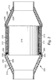
- Fig. 1 shows an exemplary erosion resistant mounting material 100 according to the present invention.
- mounting material 110 has inorganic fibers 140, optionally bonded together by a binder (not shown), and optional unexpanded intumescent particles 130.
- Mounting material 110 has a plurality of peripheral edges that include first and second peripheral edges 125, 122, respectively.
- Layer of reinforcing composition 160 comprises reinforcing composition 120 inwardly disposed on the inorganic fibers 140 along first peripheral edge 125, but does not contact a majority of the mounting material 110.
- a second layer of reinforcing composition may optionally be similarly disposed along a second peripheral edge opposite the original peripheral edge.
- the mounting material comprises inorganic fibers that are sufficiently entangled and/or bonded together to form a cohesive web.
- the fibers may be entangled by a mechanical process (for example, needletacking or hydroentangling) and/or bonded together using a binder (for example, organic binder, inorganic binder, or a combination thereof).
- a binder for example, organic binder, inorganic binder, or a combination thereof.
- the mounting material may also include organic fibers, although typically included in minor amounts, if at all.
- Useful inorganic fibers include for example, fiberglass, ceramic fibers, non-oxide inorganic fibers such as stainless steel fibers or boron fibers, and mixtures thereof.
- Useful ceramic fibers include, for example, aluminoborosilicate fibers, aluminosilicate fibers, alumina fibers, heat-treated versions thereof, and mixtures thereof.
- suitable aluminoborosilicate fibers include those commercially available under the trade designations "NEXTEL 312 CERAMIC FIBERS", “NEXTEL 440 CERAMIC FIBERS”, and “NEXTEL 550 CERAMIC FIBERS” from 3M Company, St. Paul, Minnesota.
- aluminosilicate fibers examples include those available under the trade designations "FIBERFRAX” 7000M from Unifrax Corp., Niagara Falls, New York, “CERAFIBER” from Thermal Ceramics, Augusta, Georgia; and "SNSC Type 1260 D1" from Nippon Steel Chemical Company, Tokyo, Japan.
- suitable commercially available alumina fibers include polycrystalline alumina fibers available from Saffil, Widnes, England under the trade designation "SAFFIL”.
- SAFFIL trade designation
- Suitable ceramic fibers are also disclosed in U. S. Pat. Nos. 3,795,524 (Sowman ) and 4,047,965 (Karst et al. ).
- suitable inorganic fibers include: quartz fibers, amorphous and crystalline fibers of high silica content, alumina fibers and high alumina fibers, amorphous and crystalline alumina-silica fibers, oxide and non-oxide fibers, metallic fibers, fibers formed by blowing, spinning and pulling from a melt, sol-gel formed fibers, fibers formed from organic precursors, glass fibers, leached glass fibers, and other fibers of a substantially inorganic composition.
- Suitable inorganic fibers may also comprise a surface coating or a sizing of organic and inorganic material. Suitable inorganic fibers may obviously be used alone or in combination with other suitable inorganic fibers.
- the mounting material may contain less than 50, 30, or even less than 15 percent by weight, or less, of shot based on the total dry weight of the mounting material.
- Suitable organic binders for the mounting material are known in the art and include polymers and elastomers in the latex form (for example, natural rubber latexes, styrenebutadiene latexes, butadiene-acrylonitrile latexes, and latexes of acrylate and methacrylate polymers and copolymers).
- organic binders are flocculated onto the fibers of the web using a flocculating agent, especially during wet laid manufacturing processes.
- Suitable inorganic binders are known in the art for such use and include tetrasilisic fluorine mica, in either the water-swelling unexchanged form or after flocculation as the exchanged salt with a divalent or polyvalent cation, and bentonite.
- the mounting material may comprise one or more intumescent materials (which may be unexpanded, partially expanded, expanded, or a mixture thereof), typically, depending on the desired end use.
- intumescent materials which may be unexpanded, partially expanded, expanded, or a mixture thereof
- intumescent materials typically, depending on the desired end use.
- unexpanded vermiculite materials are suitable since they start to expand at a temperature range of from about 300 °C to about 340 °C. This may be useful to fill the expanding gap between an expanding metal housing and a monolith in a catalytic converter.
- expandable graphite or a mixture of expandable graphite and unexpanded vermiculite materials may be desired since expandable graphite starts to expand or intumesce at about 210 °C.
- Treated vermiculites are also useful and typically expand at a temperature of about 290 °C.
- useful intumescent materials include unexpanded vermiculite flakes or ore, treated unexpanded vermiculite flakes or ore, partially dehydrated vermiculite ore, expandable graphite, mixtures of expandable graphite with treated or untreated unexpanded vermiculite ore, hydrobiotite, water-swellable synthetic tetrasilicic fluorine type mica (for example, as described in U. S. Pat. No. 3,001,571 (Hatch )), alkali metal silicate granules (for example, as described in U. S. Pat. No. 4,521,333 (Graham et al.
- processed expandable sodium silicate for example, insoluble sodium silicate commercially available under the trade designation "EXPANTROL” from 3M Company
- processed expandable sodium silicate for example, insoluble sodium silicate commercially available under the trade designation "EXPANTROL” from 3M Company
- An example of a commercially available expandable graphite material is that available under the trade designation "GRAFOIL Grade 338- 50" expandable graphite flake, from UCAR Carbon Co., Cleveland, Ohio.
- Treated unexpanded vermiculite flakes or ore includes unexpanded vermiculite treated by processes such as by being ion exchanged with ion exchange salts such as ammonium dihydrogen phosphate, ammonium nitrate, ammonium chloride, potassium chloride, or other suitable compounds as is known in the art.
- Factors to consider in choosing an intumescent sheet material typically include the use temperature and the type of monolith (for example, ceramic monolith or metallic monolith).
- Suitable intumescent sheet materials typically comprise unexpanded vermiculite ore (commercially available, for example, from W. R. Grace and Co., Cambridge, MA), organic binder and/or inorganic binder, ceramic fibers, and filler (for example, clay (for example, kaolin) and hollow ceramic beads or bubbles).
- U. S. Pat. No. 3,916,057 discloses intumescent sheet material comprising unexpanded vermiculite, inorganic fibrous material, and inorganic binder.
- intumescent sheet material comprising ammonium ion-treated vermiculite, inorganic fibrous material, and organic binder. Further, intumescent sheet material is commercially available, for example, from the 3M Company of St. Paul, MN, under the trade designation "INTERAM MAT MOUNT.”
- the mounting material comprises, on a dry weight basis, from 30 to 99.5 percent by weight of the inorganic fibers (for example, from 40 to 98.5 percent by weight, from 50 to 97 percent by weight, or from 60 to 97 percent by weight), from 0.5 to 12 percent by weight of an inorganic and/or organic binder (for example, from 0.5, 1.0, or 1.5 up to 3, 4, 5, 6, 7, 8, 9, 10, 11, or 12 percent by weight), and optionally up to 60 percent by weight of intumescent material, although compositions falling outside this range may also be used.
- the inorganic fibers for example, from 40 to 98.5 percent by weight, from 50 to 97 percent by weight, or from 60 to 97 percent by weight
- an inorganic and/or organic binder for example, from 0.5, 1.0, or 1.5 up to 3, 4, 5, 6, 7, 8, 9, 10, 11, or 12 percent by weight
- optionally up to 60 percent by weight of intumescent material although compositions falling outside this range may also be used.
- the percentage of inorganic fibers on a dry weight basis is typically at least 85 (for example, at least 90, 91, 92, 93, 94, 95 percent by weight, or more) percent, although lower weight percentages may also be used.
- the mounting material may optionally contain one or more inorganic fillers, inorganic binders, organic binders, organic fibers, and mixtures thereof.
- fillers examples include delaminated vermiculite, hollow glass microspheres, perlite, alumina trihydrate, calcium carbonate, and mixtures thereof. Fillers may be present in the mounting material at levels of up to 5 percent, up to 10 percent, or even up to 25 percent, or more, although use of high levels of fillers may tend to reduce the resiliency of the mounting material.
- inorganic binders examples include micaceous particles, kaolin clay, bentonite clay, and other clay-like minerals. Inorganic binders may be present in the mounting material at levels up to 5 percent, up to 10 percent, up to 15 percent, or more, based on the dry weight of the mounting material, although use of high levels of inorganic binders may tend to reduce the resiliency of the mounting material.
- organic fibers for example, staple fibers or fibrillated fibers
- additives or process aides that may be included in mounting material according to the present invention include defoaming agents, surfactants, dispersants, wetting agents, salts to aid precipitation, fungicides, and bactericides.
- the mounting material is typically formulated to have physical properties suitable for in pollution control devices, although it may be formulated with different physical properties if desired.
- the erosion resistant mounting material can be manufactured to any desired size and shape; for example, depending on specific application requirements. For example, automobile catalytic converters typically are smaller than diesel converters and generally require a correspondingly smaller mounting mat. Mounting mats can be stacked so that more than one layer of mat is wrapped around a monolith. Typically, the thickness of each intumescent erosion resistant mounting material is in the range from about 1.5 mm to about 20 mm, although other thicknesses (for example, thinner or thicker) may be used.
- the mounting material has a dry basis weight in a range of from about 400 g/m 2 to about 15 kg/m 2 , although basis weights outside of this range may also be used.
- the mounting material may have a tensile strength of at least 7.3 pounds per square inch (psi, 50 kPa), typically at least 15.5 psi (100 kPa), and more typically at least 315 psi (200 kPa) (for example, in a range of from 200-300 kPa).
- the reinforcing composition comprises (for example, consists essentially of, or even consists of) at least one compound represented by the formula: (M m+ ) d ((Z p O q (OH) r ) n- ) e •(H 2 O) f capable of rendering the first peripheral edge of the mounting material erosion resistant toward hot exhaust gases of the type found in vehicle exhaust systems.
- the compounds described by the above formula, other than phosphoric acid are salts (for example, water-soluble or water-insoluble salts).
- said at least one compound comprises a majority of the reinforcing composition.
- said at least one compound may comprise greater than 50, 55, 60, 65, 70, 75, 80, 85, 90, or even greater than 95 percent by weight of the reinforcing composition.
- Each quantity M m+ independently represents a cationic species, other than H + , having a charge of m+.
- suitable cationic species include: metal ions such as, for example, Li + , Na + , K + , Mg 2+ , Ca 2+ , Al 3+ , Fe 3+ , Cr 3+ , Cr 6+ , Ni 2+ , or Zn 2+ ; ammonium; and organic cations such as for example, sulfonium, phosphonium, and ammonium (for example, mono-, di-, tri-, or tetraalkylammonium, and benzalkonium); and organometallic cations. If alkali metal cations are used, they should be used judiciously as they may flux the inorganic fibers and have a detrimental effect on mat resiliency at temperatures above about 800 °C.
- the quantity f is a real number greater than or equal to zero (for example, 0, 1, 2, 3.4, 4.7, etc.) recognizing the existence of both integral and fractional hydrates.
- the quantities d, n, q, and r are integers greater than or equal to zero (for example, 0, 1, 2, 3, etc.).
- the quantities e, m, and p are integers greater than or equal to one (for example, 1, 2, 3, 4, etc.).
- Examples of compounds that may be included in the reinforcing composition include phosphoric acid, magnesium phosphate (for example, as prepared by sequential application of magnesium hydroxide and phosphoric acid and subsequent application), and aluminum dihydrogen phosphate.
- Certain phosphate salts encompassed by the present invention may tend to rigidify the mounting material if heated to temperatures above about 150 °C. Accordingly, they should be dried at lower temperatures.
- minor amounts of colloidal material may also be present in the solution; however, such materials tend to impart stiffness to the erosion resistant mounting material, and should typically be used judiciously in minor amounts.
- the reinforcing composition may further comprises a colorant that visually indicates the located of the reinforcing material.
- exemplary colorants include pigments and/or dyes.
- the reinforcing composition may optionally further contain additional non-interfering components such as colorants fragrances, thickeners, surfactants, dispersants, humectants, flame retardants, biocides, and the like.
- the reinforcing composition may have a low content of organic components (whether organic cationic species, organic anionic species, or neutral organic compounds).
- organic components whether organic cationic species, organic anionic species, or neutral organic compounds.
- the reinforcing composition may have an organic component content of less than 20, less than 10, or even less than 5 percent of the total weight of the reinforcing composition.
- the reinforcing composition may be formulated such that it is essentially free (that is, contains less than one percent of the total weight of the reinforcing composition on a solids basis), or even completely free of organic components.
- erosion resistance is imparted to a peripheral edge of the mounting material upon exposure to hot exhaust gases results in the reinforcing composition bonding with components of the mounting material.
- erosion resistant mounting material according to the present invention can be conveniently manufactured without the need of cumbersome retaining means such as screens or tapes to retain an edge protectant, and are typically easier to handle during installation in a pollution control device than commercially available erosion resistant mounting materials, Moreover, by applying the reinforcing layer along the peripheral edge, it is generally possible to retain much of the resiliency characteristic of the mounting material.
- the reinforcing composition can typically be handled as a solution (for example, a dryable solution) of the abovementioned compound(s) in a liquid vehicle that is applied to the mounting material by a suitable method such as, for example, dipping, roll coating, spraying, or painting, and subsequent removal of the liquid vehicle.
- a liquid vehicle may comprise, for example, water, organic solvent, or an aqueous vehicle (that is, containing water and a water soluble organic solvent).
- a solution of the reinforcing composition will have a solids content in a range of from about 1 to about 20 percent by weight, more typically from about 2 to about 15 percent, and still more typically in a range of from about 5 to about 10 percent, however higher or lower concentrations may be used as desired for specific material requirements (for example, up to about 85 percent by weight phosphoric acid may be used).
- higher coating weights of the reinforcing composition lead to equal or better erosion resistance, but lessened flexibility than lower coating weights.
- the inward depth of the layer of reinforcing material (that is, toward the center of the mounting material) and its total coating weight are typically kept to a minimum necessary to achieve a desired level of erosion resistance.
- a mounting material wherein the layer of reinforcing material is extended throughout the entirety of the mounting material (with a corresponding increase in the total coat weight of the reinforcing material) it loses a degree of flexibility and resiliency as compared to the erosion resistant mounting material of the present invention.
- the solution(s) penetrates into the interior of the mounting material, to form a layer (for example, a stripe) leaving behind, after removal of the liquid vehicle, a layer of reinforcing composition; for example, having an inward thickness (that is, distance from the peripheral edge) of less than or equal to 5, 4, 3, 2, or even less than or equal to one centimeter, although greater inward thicknesses may also be used as long as the entire mounting material is not coated by the reinforcing composition.
- Removal of the liquid vehicle may be accomplished by methods such as for example, evaporation at room temperature or at elevated temperature. Typically, lower drying temperatures are more desirable since heating at elevated temperatures (for example, above about 150 °C) may tend to rigidify the reinforcing composition. Similarly, in some embodiments it may be desirable to include a humectant in the reinforcing composition to improve flexibility.
- Erosion resistant flexible mounting materials may have any dimension and/or thickness.
- the thickness of the erosion resistant flexible mounting material, and likewise the mounting material is typically in a range of from 0.1 inch (0.3 cm), 0.15 inch (0.38 cm), or 0.2 inch (0.5 cm) up to 0.3 (0.8 cm), 0.5 (1.3 cm), 0.7 (1.8 cm) or 1 inch (2.5 cm), or more.
- the mounting material has a dry basis weight in a range of from 400, 700, 1000, 1500, or even 2000 grams per square meter (gsm) up to 5000, 10000, or 15000 gsm, or more.
- non-intumescent mounting materials typically have a dry basis weight of from 400 to 2500 gsm, more typically 1000 to 1800 gsm.
- Intumescent mounting materials typically have a dry basis weight of from 1200 to 15000 gsm, more typically 2400 to 8000 gsm.
- the mounting material may be made by any suitable technique including; for example, using air laid or wet laid techniques that are well known in the art.
- a slurry in water for example, typically greater than 95 percent by weight water
- a flocculent for example, typically greater than 95 percent by weight water
- Optional ingredients for example, defoaming agent, intumescent material or filler
- this process includes mixing the components and pouring the slurry onto a wire mesh or screen to remove most of the water.
- the formed sheet is then dried to form the mounting material.
- the mounting material may then be converted to desired forms such as sheets and mats.
- the process may be carried out in a step-wise, batch, and/or continuous fashion.
- higher density materials such as the optional intumescent material and higher density fillers (if used) may be added to the slurry in a smaller volume mixing vessel at a constant rate just prior to the depositing step.
- Slurries containing fillers and intumescent materials are agitated sufficiently so to prevent these particles from settling out in the mixing tank prior to pouring the slurry onto the mesh.
- Such slurries should typically be partially dewatered almost immediately after being deposited on the mesh so to prevent undesirable settling of the higher density particles.
- Vacuum dewatering of the slurries is desirable.
- Useful drying methods include wet pressing the dewatered slurries through compression or pressure rollers followed by passing the material through heated rollers and forced hot air drying as is known in the art.
- Erosion resistant mounting material is useful in pollution control devices as mounting material (for example, a mounting mat) for mounting a monolith in a housing and/or for end cone insulation.
- the erosion resistant mounting material may be disposed between the monolith and the housing by wrapping the monolith with the erosion resistant mounting material and inserting the wrapped monolith into the housing, or by wrapping the inner end cone housing with the erosion resistant mounting material and then welding the outer end cone housing to the inner end cone housing.
- the reinforcing composition treated peripheral edge of the erosion resistant mounting material is generally directed toward the upstream portion of the exhaust path, although backside turbulence should also be considered.
- the reinforcing composition is activatable by heat. Once activated (for example, from hot exhaust gases, flame, or an oven prior to installation on the vehicle), it enhances erosion resistance of the edge of the mounting material proximate which it is disposed. Typically, a temperature in a range of from about 150 °C to about 300 °C activates the reinforcing composition, although temperatures outside this range may also be used. Activation may be achieved by exposure to the inherent temperature of a pollution control device (for example, a catalytic converter). In cases where a pollution control device has an operational temperature that is less than the activation temperature of the reinforcing material, heating the pollution control device to a temperature in excess of the activation temperature prior to installing it on a vehicle may be advantageous.
- a pollution control device for example, a catalytic converter
- exemplary pollution control device 200 includes housing 212 and has a generally conical inlet 214 and outlet 216 (that is, commonly referred to as end cones).
- Housing 212 which is commonly referred to as a can or a casing, is usually made of metal (for example, stainless steel).
- monolith 218 usually made of a ceramic or metallic material, and which may include a catalyst.
- Erosion resistant mounting material 210 surrounds monolith 218.
- First edge 225 of erosion resistant mounting material 210 with layer of reinforcing composition 260 is oriented toward inlet 214.
- Monolith 218 may be, for example, a catalytic converter element or a diesel particulate filter element.
- Inlet 214 and outlet 216 include an inner end cone housing 228 and an outer end cone housing 226.
- Insulation material 230 is positioned between the inner end cone housing 228 and the outer end cone housing 226.
- Erosion resistant flexible mounting material according to the present invention may be used as insulation material 230. If so, the layer of reinforcing composition is typically oriented toward the monolith, but this is not a requirement.
- pollution control devices include, for example, catalytic converters, end cone sub-assemblies, selective catalytic reduction (SCR) units, and diesel particulate traps and filters. Further details concerning such devices may be found, for example, in U. S. Pat. Nos. 5,882,608 (Sanocki et al. ), 6,245,301 (Stroom et al. ) and RE 27,747 (Johnson ), and in U. S. Publ. Pat. Appln. No. 2006/0154040 A1 (Merry ).
- a specimen to be tested is sized (typically cut) to form a strip, 1 inch (2.5 cm) wide x 7 inches (18 cm) long, such that any reinforcing composition that is present lies along a 7-inch (18-cm) side (that is, a treated edge).
- the specimen is wrapped lengthwise around a 2.5-inch (6.4-cm) diameter steel mandrel such that the treated edge (if any) is wrapped around the circumference of the mandrel.
- the specimen passes this test if it conforms to the circumference of the mandrel without cracking in half or breaking into large ridged segments. A small degree of surface cracking is acceptable. Any specimen that cracks through the majority of the entire thickness of the specimen is considered a failure.
- a specimen to be tested is cut into a square measuring one inch by one inch (2.54 cm by 2.54 cm), weighed, and mounted horizontally between two metal plates (nickel/chromium alloy, available under the trade designation "INCONEL 601" from Inco Alloys International, Huntington, WV) using metallic spacers to obtain a desired mount density and leaving the treated edge exposed.
- Mount density is achieved by compressing the specimen evenly between the metallic spacers to a uniform thickness.
- the mount density is then calculated as the basis weight of the specimen divided by the thickness of the compressed specimen.
- the resultant assembly is heated for two hours at 800 °C, and then cooled to room temperature. The weight after binder burn out is recorded.
- the assembly is then positioned at a distance of 3.8 mm in front of an air jet oscillating back and forth over the treated edge of the mat at 20 cycles per minute for 24 hrs.
- the air jet impinges on the treated edge of the specimen at a velocity of 178 meters per second.
- the specimen is re-weighed to determine weight loss.
- the erosion rate is determined by the weight loss after binder burnout divided by the time of the test and is reported in grams lost per hour (g/hr).
- a specimen to be tested is cut into a square measuring one inch by one inch (2.54 cm by 2.54 cm), weighed, and mounted horizontally between two metal plates (nickel/chromium alloy, available under the trade designation INCONEL 601 from Inco Alloys International, Huntington, WV) using metallic spacers to obtain a desired mount density and leaving the treated edge exposed.
- the resultant assembly is heated for two hours at 800 °C, and then cooled to room temperature. The weight after binder burn out is recorded.
- the assembly is then positioned at a distance of 3.8 mm in front of an air jet heated at 500 °C oscillating back and forth over the treated edge of the mat at 20 cycles per minute for 24 hrs.
- the air jet impinges on the treated edge of the specimen at a velocity of 178 meters per second.
- the upper metal plate is heated at 800 °C and the lower metal plate is heated at 475 °C.
- the erosion rate is determined by the weight loss after binder burnout divided by the time of the test and is reported in grams lost per hour (g/hr).
- edge treatments were applied to MAT1 according to the following procedure.
- the edge treatment material was dissolved in the indicated solvent(s) and allowed to stabilize over night.
- Specimens, 7 inches (18 cm) x 7 inches (18 cm), of MAT1 were cut from a common roll. One edge of each sample was dipped into a shallow pan containing a solution as indicated in Table 2. The pan was a 9 inches x 12 inches (23cm x 30.5 cm) and about 1 inch deep (2.5 cm). The pan was position with a slight incline (15 degrees) to concentrate the solution to the 9 inch side of the pan. Typically, less than five seconds was enough time to allow capillary action to wick the solution evenly into the support mat. The procedure was repeated for each experimental condition. After the samples were dipped in the solution they were allowed to dry overnight at room temperature.
- edge treatments were applied to MAT4 according to the following procedure.
- the edge treatment material was dissolved in the indicated solvent(s) and allowed to stabilize over night.
- Specimens, 7 inches (18 cm) x 7 inches (18 cm), of MAT4 were cut from a common roll. One edge of each sample was dipped into a shallow pan containing approximately 10 grams of solution as indicated in Table 3. The pan was a 9 inches x 12 inches (23cm x 30.5 cm) and about 1 inch deep (2.5 cm). The pan was position with a slight incline (15 degrees) to concentrate the solution to the 9 inch side of the pan. Typically, less than five seconds was enough time to allow capillary action to wick the solution evenly into the support mat. The procedure was repeated for each experimental condition. After the samples were dipped in the solution they were allowed to dry overnight at room temperature.
- edge treatments were applied to MAT5 according to the following procedure.
- the edge treatment material was dissolved in the indicated solvent(s) and allowed to stabilize over night.
- Specimens, 7 inches (18 cm) x 7 inches (18 cm), of MAT5 were cut from a common roll. One edge of each sample was dipped into a shallow pan containing 5 grams of a solution as indicated in Table 4. The pan was a 9 inches x 12 inches (23cm x 30.5 cm) and about 1 inch deep (2.5 cm). The pan was position with a slight incline (15 degrees) to concentrate the solution to the 9 inch side of the pan. Typically, less than five seconds was enough time to allow capillary action to wick the solution evenly into the support mat. The procedure was repeated for each experimental condition. After the samples were dipped in the solution they were allowed to dry overnight at room temperature.
- Example 11 Two drops of SURF2 was added for every 100 grams of water-based solution to aide absorption into the mat. Prior to application, water-based solutions and the pan were heated to 80 °C. The specimens were tested according to the Cold Erosion Test. The mount density was 0.59 g/cm 3 . The observed erosion rate in grams per hour is reported in Table 4 (below). For Example 11 the mat was first dipped into 2 grams of 10% MAP, then while still wet dipped into 3 grams of 10% boric acid solution both at 80 °C.
- Edge treatments were applied to MAT1 according to the following procedure.
- the edge treatment material was dissolved in the indicated solvent and allowed to stabilize over night.
- Specimens, 7 inches (18 cm) x 7 inches (18 cm), of MAT1 were cut from a common roll. One edge of each sample was dipped into a shallow pan containing approximately 10 grams of the solution as indicated in Table 5. The pan was a 9 inches x 12 inches (23 cm x 30.5 cm) and about 1 inch deep (2.5 cm). The pan was position with a slight incline (15 degrees) to concentrate the solution to the 9-inch side of the pan. Typically, less than five seconds was enough time to allow capillary action to wick the solution evenly into the support mat. The procedure was repeated for each experimental condition. After the samples were dipped in the solution they were allowed to dry overnight at room temperature.
Landscapes
- Chemical & Material Sciences (AREA)
- Engineering & Computer Science (AREA)
- Ceramic Engineering (AREA)
- Organic Chemistry (AREA)
- Materials Engineering (AREA)
- Structural Engineering (AREA)
- Inorganic Chemistry (AREA)
- Chemical Kinetics & Catalysis (AREA)
- Combustion & Propulsion (AREA)
- Mechanical Engineering (AREA)
- General Engineering & Computer Science (AREA)
- Health & Medical Sciences (AREA)
- Toxicology (AREA)
- Exhaust Gas After Treatment (AREA)
- Laminated Bodies (AREA)
Priority Applications (1)
| Application Number | Priority Date | Filing Date | Title |
|---|---|---|---|
| PL12165307T PL2487342T3 (pl) | 2007-06-13 | 2008-05-19 | Materiał montażowy odporny na erozję oraz sposób jego wytwarzania i stosowania |
Applications Claiming Priority (3)
| Application Number | Priority Date | Filing Date | Title |
|---|---|---|---|
| US94368807P | 2007-06-13 | 2007-06-13 | |
| US99244907P | 2007-12-05 | 2007-12-05 | |
| EP08755851.6A EP2171227B8 (en) | 2007-06-13 | 2008-05-19 | Erosion resistant mounting material and method of making and using the same |
Related Parent Applications (3)
| Application Number | Title | Priority Date | Filing Date |
|---|---|---|---|
| EP08755851.6 Division | 2008-05-19 | ||
| EP08755851.6A Division EP2171227B8 (en) | 2007-06-13 | 2008-05-19 | Erosion resistant mounting material and method of making and using the same |
| EP08755851.6A Division-Into EP2171227B8 (en) | 2007-06-13 | 2008-05-19 | Erosion resistant mounting material and method of making and using the same |
Publications (2)
| Publication Number | Publication Date |
|---|---|
| EP2487342A1 EP2487342A1 (en) | 2012-08-15 |
| EP2487342B1 true EP2487342B1 (en) | 2018-04-18 |
Family
ID=39712127
Family Applications (2)
| Application Number | Title | Priority Date | Filing Date |
|---|---|---|---|
| EP08755851.6A Active EP2171227B8 (en) | 2007-06-13 | 2008-05-19 | Erosion resistant mounting material and method of making and using the same |
| EP12165307.5A Active EP2487342B1 (en) | 2007-06-13 | 2008-05-19 | Erosion resistant mounting material and method of making and using the same |
Family Applications Before (1)
| Application Number | Title | Priority Date | Filing Date |
|---|---|---|---|
| EP08755851.6A Active EP2171227B8 (en) | 2007-06-13 | 2008-05-19 | Erosion resistant mounting material and method of making and using the same |
Country Status (7)
| Country | Link |
|---|---|
| US (1) | US8617475B2 (pl) |
| EP (2) | EP2171227B8 (pl) |
| JP (1) | JP5551588B2 (pl) |
| KR (2) | KR101547710B1 (pl) |
| CN (1) | CN101730788B (pl) |
| PL (1) | PL2487342T3 (pl) |
| WO (1) | WO2008156942A1 (pl) |
Families Citing this family (29)
| Publication number | Priority date | Publication date | Assignee | Title |
|---|---|---|---|---|
| US8702832B2 (en) | 2007-06-13 | 2014-04-22 | 3M Innovative Properties Company | Securable mounting material and method of making and using the same |
| KR101547710B1 (ko) | 2007-06-13 | 2015-08-26 | 쓰리엠 이노베이티브 프로퍼티즈 컴파니 | 내침식성 장착 재료와 그 제조 및 사용 방법 |
| ES2460871T3 (es) | 2008-08-29 | 2014-05-14 | Unifrax I Llc | Estera de montaje con protección flexible de orillas y dispositivo de tratamiento de gases de escape que incorpora la estera de montaje |
| BRPI0923515A2 (pt) | 2008-12-15 | 2016-01-26 | Unifrax I Llc | revestimento de cobertura para estrutura em cerâmica em forma de colméia |
| EP2406073B1 (en) | 2009-03-13 | 2020-04-22 | 3M Innovative Properties Company | Mat and devices with the same |
| CN102459834B (zh) | 2009-04-17 | 2017-02-08 | 尤尼弗瑞克斯 I 有限责任公司 | 排气处理装置 |
| GB0906837D0 (en) * | 2009-04-21 | 2009-06-03 | Saffil Automotive Ltd | Mats |
| KR20120041207A (ko) * | 2009-07-09 | 2012-04-30 | 쓰리엠 이노베이티브 프로퍼티즈 컴파니 | 튜브형이고 연속적이며 이음매 없는 압축성의 탄성 장착 물품 및 이를 포함하는 오염 제어 장치 |
| WO2011019377A2 (en) | 2009-08-10 | 2011-02-17 | Unifrax I Llc | Variable basis weight mounting mat or pre-form and exhaust gas treatment device |
| EP2464836A2 (en) | 2009-08-14 | 2012-06-20 | Unifrax I LLC | Mounting mat for exhaust gas treatment device |
| CN102686843B (zh) | 2009-08-14 | 2015-04-01 | 尤尼弗瑞克斯I有限责任公司 | 多层基底支承体和排气处理装置 |
| US8071040B2 (en) | 2009-09-23 | 2011-12-06 | Unifax I LLC | Low shear mounting mat for pollution control devices |
| EP2480765A1 (en) | 2009-09-24 | 2012-08-01 | Unifrax I LLC | Multiple layer mat and exhaust gas treatment device |
| EP2488735B1 (en) | 2009-10-13 | 2014-05-07 | 3M Innovative Properties Company | Non-woven mat and pollution control device with the same |
| CN102713187B (zh) | 2009-12-01 | 2016-05-04 | 萨菲尔汽车有限公司 | 安装垫 |
| CN102753795B (zh) | 2009-12-17 | 2016-02-17 | 尤尼弗瑞克斯I有限责任公司 | 微球体在废气处理装置安装垫中的用途 |
| CN106884701A (zh) | 2009-12-17 | 2017-06-23 | 尤尼弗瑞克斯 I 有限责任公司 | 用于废气处理装置的安装垫 |
| CN102770630B (zh) | 2009-12-17 | 2016-02-17 | 尤尼弗瑞克斯I有限责任公司 | 用于污染控制装置的多层安装垫 |
| WO2012021817A2 (en) | 2010-08-12 | 2012-02-16 | Unifrax I Llc | Exhaust gas treatment device |
| ES2569370T3 (es) * | 2010-08-13 | 2016-05-10 | Unifrax I Llc | Estera de montaje con protección flexible de bordes y dispositivo de tratamiento de gases de escape con la estera de montaje incorporada |
| US9924564B2 (en) | 2010-11-11 | 2018-03-20 | Unifrax I Llc | Heated mat and exhaust gas treatment device |
| WO2012065052A2 (en) | 2010-11-11 | 2012-05-18 | Unifrax I Llc | Mounting mat and exhaust gas treatment device |
| KR20140067137A (ko) | 2011-09-22 | 2014-06-03 | 쓰리엠 이노베이티브 프로퍼티즈 컴파니 | 배기 계통을 위한 열적으로 절연된 구성요소 |
| JP6012968B2 (ja) * | 2012-01-23 | 2016-10-25 | ニチアス株式会社 | 気体処理装置用保持材、気体処理装置及びこれらの製造方法 |
| US10328372B2 (en) * | 2014-06-19 | 2019-06-25 | Corning Incorporated | Anti-microbial air filter |
| JP6483408B2 (ja) * | 2014-11-07 | 2019-03-13 | イビデン株式会社 | 保持シール材 |
| PT3034825T (pt) * | 2014-12-18 | 2017-12-14 | 3M Innovative Properties Co | Tapete de montagem para um dispositivo de tratamento de gás de escape |
| KR20170118679A (ko) | 2015-02-24 | 2017-10-25 | 유니프랙스 아이 엘엘씨 | 내고온성 절연 매트 |
| CN115680847A (zh) * | 2018-06-21 | 2023-02-03 | 3M创新有限公司 | 垫材料、其制造方法、污染控制装置和隔热结构 |
Family Cites Families (70)
| Publication number | Priority date | Publication date | Assignee | Title |
|---|---|---|---|---|
| US3444925A (en) * | 1957-05-07 | 1969-05-20 | Minnesota Mining & Mfg | Structural articles and method of making |
| CA637172A (en) | 1957-08-05 | 1962-02-27 | A. Hatch Robert | Synthetic mica, mica products and method of making |
| US3795524A (en) | 1971-03-01 | 1974-03-05 | Minnesota Mining & Mfg | Aluminum borate and aluminum borosilicate articles |
| US3798006A (en) * | 1971-12-14 | 1974-03-19 | Tenneco Inc | Catalytic converter for exhuast gases |
| DE2261663C2 (de) | 1972-12-16 | 1983-07-14 | Fa. J. Eberspächer, 7300 Esslingen | Elastische Lagerung für keramische Katalysatorträger |
| JPS49113024A (pl) * | 1973-03-02 | 1974-10-28 | ||
| US3916057A (en) | 1973-08-31 | 1975-10-28 | Minnesota Mining & Mfg | Intumescent sheet material |
| US4163041A (en) | 1974-05-29 | 1979-07-31 | J. Eberspacher | Support for elastically mounting a ceramic honeycomb catalyst |
| US3948611A (en) | 1974-06-10 | 1976-04-06 | Engelhard Minerals & Chemicals Corporation | Catalytic converter having hollow, gas-filled mounting means for a monolithic catalyst |
| US4047965A (en) | 1976-05-04 | 1977-09-13 | Minnesota Mining And Manufacturing Company | Non-frangible alumina-silica fibers |
| US4142864A (en) | 1977-05-31 | 1979-03-06 | Engelhard Minerals & Chemicals Corporation | Catalytic apparatus |
| US4156533A (en) | 1978-04-28 | 1979-05-29 | Minnesota Mining And Manufacturing Company | High temperature gasket |
| US4305992A (en) | 1979-11-28 | 1981-12-15 | Minnesota Mining And Manufacturing Company | Intumescent sheet material |
| JPS56162220A (en) | 1980-05-20 | 1981-12-14 | Ngk Insulators Ltd | Ceramic honeycomb structural body |
| US4521333A (en) | 1983-06-20 | 1985-06-04 | Minnesota Mining And Manufacturing Company | Intumescent silicates having improved stability |
| DE3514150C1 (de) | 1985-04-19 | 1986-04-10 | LEISTRITZ Maschinenfabrik GmbH, 8500 Nürnberg | Katalytische Abgasentgiftungsvorrichtung mit stabilisierter Federmatte |
| FR2585071B1 (fr) | 1985-07-16 | 1987-11-27 | Peugeot Cycles | Pot d'echappement pour vehicule automobile ou analogue |
| US4683010A (en) | 1985-10-01 | 1987-07-28 | Acs Industries, Inc. | Compacted wire seal and method of forming same |
| US4929429A (en) | 1988-02-11 | 1990-05-29 | Minnesota Mining And Manufacturing Company | Catalytic converter |
| US5008086A (en) | 1988-10-28 | 1991-04-16 | Minnesota Mining And Manufacturing Company | Erosion resistant mounting composite for catalytic converter |
| US4999168A (en) | 1989-05-01 | 1991-03-12 | The Carborundum Company | Crack resistant intumescent sheet material |
| US4939429A (en) * | 1989-08-24 | 1990-07-03 | Rca Licensing Corporation | High voltage regulator circuit for picture tube |
| JPH04348178A (ja) | 1990-04-26 | 1992-12-03 | Takeda Chem Ind Ltd | 熱硬化性ホットメルト接着剤 |
| US5212279A (en) | 1990-10-22 | 1993-05-18 | Hitachi Chemical Co., Ltd. | Hot-melt adhesive and its use in polyimide film and printed circuit board |
| US5207989A (en) | 1991-03-22 | 1993-05-04 | Acs Industries, Inc. | Seal for catalytic converter and method therefor |
| CA2152085C (en) | 1993-01-07 | 2004-04-27 | John J. Rogers | Flexible nonwoven mat |
| US5332609A (en) | 1993-03-25 | 1994-07-26 | Minnesota Mining And Manufacturing Company | Intumescent mounting mat |
| JP3520530B2 (ja) * | 1993-07-28 | 2004-04-19 | 三菱化学株式会社 | 炭素繊維強化炭素複合材および摺動材 |
| JPH0769751A (ja) | 1993-08-20 | 1995-03-14 | Minnesota Mining & Mfg Co <3M> | 積層マットのエッジ保護、及び高温封止材料を有する積層マット |
| US6245301B1 (en) * | 1993-08-20 | 2001-06-12 | 3M Innovative Properties Company | Catalytic converter and diesel particulate filter |
| KR950006447A (ko) | 1993-08-20 | 1995-03-21 | 테릴 켄트 쿠 알리 | 고온 밀봉재를 지닌 장착용 매트 |
| US5853675A (en) | 1995-06-30 | 1998-12-29 | Minnesota Mining And Manufacturing Company | Composite mounting system |
| US5736109A (en) | 1995-06-30 | 1998-04-07 | Minnesota Mining And Manufacturing Company | Intumescent sheet material and paste with organic binder |
| US5714237A (en) | 1996-01-16 | 1998-02-03 | Minnesota Mining Manufacturing Company | Partially crosslinked microspheres |
| KR100540028B1 (ko) * | 1996-06-18 | 2006-03-14 | 미네소타 마이닝 앤드 매뉴팩춰링 캄파니 | 자립형내부단열라이너 |
| US5882608A (en) * | 1996-06-18 | 1999-03-16 | Minnesota Mining And Manufacturing Company | Hybrid mounting system for pollution control devices |
| US6726884B1 (en) * | 1996-06-18 | 2004-04-27 | 3M Innovative Properties Company | Free-standing internally insulating liner |
| US6881548B2 (en) | 1997-05-23 | 2005-04-19 | A&G Pharmaceutical, Inc. | Methods and kits for diagnosing tumorigenicity and determining resistance to the antineoplastic effects of antiestrogen therapy |
| DE19803063A1 (de) * | 1998-01-28 | 1999-07-29 | Eberspaecher J Gmbh & Co | Verfahren zur Halterung und Isolation von Keramikmonolithen in einer Kraftfahrzeug-Abgasanlage einschließlich hiernach gefertigte Lagerung |
| JP2002523261A (ja) | 1998-08-24 | 2002-07-30 | ミネソタ マイニング アンド マニュファクチャリング カンパニー | 汚染制御装置用の装着材料 |
| JP3715127B2 (ja) | 1999-02-22 | 2005-11-09 | 本田技研工業株式会社 | 触媒コンバータ |
| US6368394B1 (en) | 1999-10-18 | 2002-04-09 | Sermatech International, Inc. | Chromate-free phosphate bonding composition |
| JP4042305B2 (ja) | 2000-06-21 | 2008-02-06 | イビデン株式会社 | 排気ガス浄化用触媒コンバータの保持シール材 |
| US6966945B1 (en) | 2000-09-20 | 2005-11-22 | Goodrich Corporation | Inorganic matrix compositions, composites and process of making the same |
| US7524546B2 (en) | 2000-12-28 | 2009-04-28 | 3M Innovative Properties Company | Thermal insulating material and pollution control device using the same |
| JP4730495B2 (ja) | 2001-05-25 | 2011-07-20 | イビデン株式会社 | 触媒コンバータ用保持シール材及びその製造方法、触媒コンバータ |
| US8012889B2 (en) | 2001-11-07 | 2011-09-06 | Flexform Technologies, Llc | Fire retardant panel composition and methods of making the same |
| JP3826083B2 (ja) * | 2002-08-26 | 2006-09-27 | イビデン株式会社 | 触媒コンバータ用シール材 |
| KR101148724B1 (ko) * | 2003-01-22 | 2012-05-29 | 쓰리엠 이노베이티브 프로퍼티즈 컴파니 | 성형 3차원 절연체 |
| CN100548927C (zh) * | 2003-01-22 | 2009-10-14 | 3M创新有限公司 | 模制的三维隔热体 |
| KR101106867B1 (ko) | 2003-01-31 | 2012-01-19 | 쓰리엠 이노베이티브 프로퍼티즈 컴파니 | 오염 제어 장치의 단부 원추 또는 장착 매트 고정 시스템 |
| US6864199B2 (en) | 2003-02-07 | 2005-03-08 | Allied Mineral Products, Inc. | Crack-resistant dry refractory |
| JP2003336005A (ja) * | 2003-04-03 | 2003-11-28 | Tozai Kagaku Kk | 耐食性コーティング組成物、塗料およびその塗膜 |
| EP1495807A1 (en) | 2003-06-30 | 2005-01-12 | 3M Innovative Properties Company | Mounting mat for mounting monolith in a pollution control device |
| JP2005074243A (ja) | 2003-08-29 | 2005-03-24 | Three M Innovative Properties Co | 汚染コントロール要素の保持材及び汚染コントロール装置 |
| US7550118B2 (en) | 2004-04-14 | 2009-06-23 | 3M Innovative Properties Company | Multilayer mats for use in pollution control devices |
| FR2869948B1 (fr) | 2004-05-05 | 2008-08-01 | Faurecia Sys Echappement | Nappe de support d'un organe de traitement des gaz d'echappement, dispositif, procede de fabrication et ligne d'echappement associes |
| WO2006055188A1 (en) * | 2004-11-18 | 2006-05-26 | 3M Innovative Properties Company | A pollution control device and inorganic fiber sheet material with a fused edge |
| JP2006289237A (ja) | 2005-04-08 | 2006-10-26 | Ibiden Co Ltd | ハニカム構造体 |
| US20070111878A1 (en) | 2005-11-16 | 2007-05-17 | Bilal Zuberi | Extrudable mixture for forming a porous block |
| KR101489005B1 (ko) * | 2006-06-01 | 2015-02-02 | 쓰리엠 이노베이티브 프로퍼티즈 컴파니 | 다층 장착 매트 |
| WO2008059576A1 (en) | 2006-11-16 | 2008-05-22 | Ibiden Co., Ltd. | Honeycomb structural body and method of producing the same |
| EP2118364B1 (en) | 2007-02-19 | 2014-07-30 | 3M Innovative Properties Company | Flexible fibrous material, pollution control device, and methods of making the same |
| WO2008120385A1 (ja) | 2007-03-29 | 2008-10-09 | Ibiden Co., Ltd. | ハニカム構造体、ハニカム構造体の製造方法、排ガス浄化装置及び排ガス浄化装置の製造方法 |
| US8702832B2 (en) | 2007-06-13 | 2014-04-22 | 3M Innovative Properties Company | Securable mounting material and method of making and using the same |
| KR101547710B1 (ko) | 2007-06-13 | 2015-08-26 | 쓰리엠 이노베이티브 프로퍼티즈 컴파니 | 내침식성 장착 재료와 그 제조 및 사용 방법 |
| JP2010529368A (ja) | 2007-06-13 | 2010-08-26 | スリーエム イノベイティブ プロパティズ カンパニー | 再付着性マウント材料、汚染防止装置、及びその製造方法 |
| CN101939359B (zh) | 2007-10-22 | 2015-09-09 | 弗莱克斯伯陶器公司 | 耐火的柔性陶瓷树脂共混物以及由其形成的复合材料制品 |
| WO2009118873A1 (ja) | 2008-03-27 | 2009-10-01 | イビデン株式会社 | ハニカム構造体 |
| WO2009141873A1 (ja) | 2008-05-20 | 2009-11-26 | イビデン株式会社 | ハニカム構造体 |
-
2008
- 2008-05-19 KR KR1020107000367A patent/KR101547710B1/ko not_active Expired - Fee Related
- 2008-05-19 KR KR1020157012141A patent/KR101595711B1/ko not_active Expired - Fee Related
- 2008-05-19 US US12/663,712 patent/US8617475B2/en active Active
- 2008-05-19 WO PCT/US2008/064091 patent/WO2008156942A1/en not_active Ceased
- 2008-05-19 JP JP2010512240A patent/JP5551588B2/ja active Active
- 2008-05-19 CN CN2008800202190A patent/CN101730788B/zh active Active
- 2008-05-19 PL PL12165307T patent/PL2487342T3/pl unknown
- 2008-05-19 EP EP08755851.6A patent/EP2171227B8/en active Active
- 2008-05-19 EP EP12165307.5A patent/EP2487342B1/en active Active
Non-Patent Citations (1)
| Title |
|---|
| None * |
Also Published As
| Publication number | Publication date |
|---|---|
| CN101730788B (zh) | 2013-06-19 |
| PL2487342T3 (pl) | 2018-08-31 |
| JP2010528857A (ja) | 2010-08-26 |
| EP2487342A1 (en) | 2012-08-15 |
| KR20150058547A (ko) | 2015-05-28 |
| JP5551588B2 (ja) | 2014-07-16 |
| KR101595711B1 (ko) | 2016-02-18 |
| KR20100041756A (ko) | 2010-04-22 |
| EP2171227B8 (en) | 2016-06-01 |
| WO2008156942A1 (en) | 2008-12-24 |
| EP2171227A1 (en) | 2010-04-07 |
| US20110182777A1 (en) | 2011-07-28 |
| CN101730788A (zh) | 2010-06-09 |
| KR101547710B1 (ko) | 2015-08-26 |
| EP2171227B1 (en) | 2016-04-20 |
| US8617475B2 (en) | 2013-12-31 |
Similar Documents
| Publication | Publication Date | Title |
|---|---|---|
| EP2487342B1 (en) | Erosion resistant mounting material and method of making and using the same | |
| EP2173981B1 (en) | Securable mounting material and method of making and using the same | |
| US20200224367A1 (en) | Flexible fibrous material, pollution control device, and methods of making the same | |
| EP1674684B1 (en) | Multilayer intumescent sheet | |
| CA2278486C (en) | Multilayer intumescent sheet | |
| US5523059A (en) | Intumescent sheet material with glass fibers | |
| US20170198622A1 (en) | Thermally Stable Inorganic Fibers For Exhaust Gas Treatment Device Insulating Mat | |
| JP2023048673A (ja) | 保持シール材、保持シール材の製造方法及び排ガス浄化装置 | |
| WO2016100079A1 (en) | Mounting mat for an exhaust gas treatment device |
Legal Events
| Date | Code | Title | Description |
|---|---|---|---|
| PUAI | Public reference made under article 153(3) epc to a published international application that has entered the european phase |
Free format text: ORIGINAL CODE: 0009012 |
|
| AC | Divisional application: reference to earlier application |
Ref document number: 2171227 Country of ref document: EP Kind code of ref document: P |
|
| AK | Designated contracting states |
Kind code of ref document: A1 Designated state(s): AT BE BG CH CY CZ DE DK EE ES FI FR GB GR HR HU IE IS IT LI LT LU LV MC MT NL NO PL PT RO SE SI SK TR |
|
| 17P | Request for examination filed |
Effective date: 20130131 |
|
| 17Q | First examination report despatched |
Effective date: 20140623 |
|
| GRAP | Despatch of communication of intention to grant a patent |
Free format text: ORIGINAL CODE: EPIDOSNIGR1 |
|
| STAA | Information on the status of an ep patent application or granted ep patent |
Free format text: STATUS: GRANT OF PATENT IS INTENDED |
|
| INTG | Intention to grant announced |
Effective date: 20170310 |
|
| GRAS | Grant fee paid |
Free format text: ORIGINAL CODE: EPIDOSNIGR3 |
|
| GRAJ | Information related to disapproval of communication of intention to grant by the applicant or resumption of examination proceedings by the epo deleted |
Free format text: ORIGINAL CODE: EPIDOSDIGR1 |
|
| GRAL | Information related to payment of fee for publishing/printing deleted |
Free format text: ORIGINAL CODE: EPIDOSDIGR3 |
|
| STAA | Information on the status of an ep patent application or granted ep patent |
Free format text: STATUS: EXAMINATION IS IN PROGRESS |
|
| INTC | Intention to grant announced (deleted) | ||
| GRAP | Despatch of communication of intention to grant a patent |
Free format text: ORIGINAL CODE: EPIDOSNIGR1 |
|
| STAA | Information on the status of an ep patent application or granted ep patent |
Free format text: STATUS: GRANT OF PATENT IS INTENDED |
|
| INTG | Intention to grant announced |
Effective date: 20171117 |
|
| GRAA | (expected) grant |
Free format text: ORIGINAL CODE: 0009210 |
|
| STAA | Information on the status of an ep patent application or granted ep patent |
Free format text: STATUS: THE PATENT HAS BEEN GRANTED |
|
| REG | Reference to a national code |
Ref country code: FR Ref legal event code: PLFP Year of fee payment: 11 |
|
| AC | Divisional application: reference to earlier application |
Ref document number: 2171227 Country of ref document: EP Kind code of ref document: P |
|
| AK | Designated contracting states |
Kind code of ref document: B1 Designated state(s): AT BE BG CH CY CZ DE DK EE ES FI FR GB GR HR HU IE IS IT LI LT LU LV MC MT NL NO PL PT RO SE SI SK TR |
|
| REG | Reference to a national code |
Ref country code: GB Ref legal event code: FG4D |
|
| REG | Reference to a national code |
Ref country code: CH Ref legal event code: EP |
|
| REG | Reference to a national code |
Ref country code: AT Ref legal event code: REF Ref document number: 990724 Country of ref document: AT Kind code of ref document: T Effective date: 20180515 |
|
| REG | Reference to a national code |
Ref country code: IE Ref legal event code: FG4D |
|
| REG | Reference to a national code |
Ref country code: DE Ref legal event code: R096 Ref document number: 602008054946 Country of ref document: DE |
|
| REG | Reference to a national code |
Ref country code: SE Ref legal event code: TRGR |
|
| REG | Reference to a national code |
Ref country code: NL Ref legal event code: MP Effective date: 20180418 |
|
| REG | Reference to a national code |
Ref country code: LT Ref legal event code: MG4D |
|
| PG25 | Lapsed in a contracting state [announced via postgrant information from national office to epo] |
Ref country code: NL Free format text: LAPSE BECAUSE OF FAILURE TO SUBMIT A TRANSLATION OF THE DESCRIPTION OR TO PAY THE FEE WITHIN THE PRESCRIBED TIME-LIMIT Effective date: 20180418 |
|
| PG25 | Lapsed in a contracting state [announced via postgrant information from national office to epo] |
Ref country code: LT Free format text: LAPSE BECAUSE OF FAILURE TO SUBMIT A TRANSLATION OF THE DESCRIPTION OR TO PAY THE FEE WITHIN THE PRESCRIBED TIME-LIMIT Effective date: 20180418 Ref country code: FI Free format text: LAPSE BECAUSE OF FAILURE TO SUBMIT A TRANSLATION OF THE DESCRIPTION OR TO PAY THE FEE WITHIN THE PRESCRIBED TIME-LIMIT Effective date: 20180418 Ref country code: NO Free format text: LAPSE BECAUSE OF FAILURE TO SUBMIT A TRANSLATION OF THE DESCRIPTION OR TO PAY THE FEE WITHIN THE PRESCRIBED TIME-LIMIT Effective date: 20180718 Ref country code: BG Free format text: LAPSE BECAUSE OF FAILURE TO SUBMIT A TRANSLATION OF THE DESCRIPTION OR TO PAY THE FEE WITHIN THE PRESCRIBED TIME-LIMIT Effective date: 20180718 Ref country code: ES Free format text: LAPSE BECAUSE OF FAILURE TO SUBMIT A TRANSLATION OF THE DESCRIPTION OR TO PAY THE FEE WITHIN THE PRESCRIBED TIME-LIMIT Effective date: 20180418 |
|
| PG25 | Lapsed in a contracting state [announced via postgrant information from national office to epo] |
Ref country code: LV Free format text: LAPSE BECAUSE OF FAILURE TO SUBMIT A TRANSLATION OF THE DESCRIPTION OR TO PAY THE FEE WITHIN THE PRESCRIBED TIME-LIMIT Effective date: 20180418 Ref country code: HR Free format text: LAPSE BECAUSE OF FAILURE TO SUBMIT A TRANSLATION OF THE DESCRIPTION OR TO PAY THE FEE WITHIN THE PRESCRIBED TIME-LIMIT Effective date: 20180418 Ref country code: GR Free format text: LAPSE BECAUSE OF FAILURE TO SUBMIT A TRANSLATION OF THE DESCRIPTION OR TO PAY THE FEE WITHIN THE PRESCRIBED TIME-LIMIT Effective date: 20180719 |
|
| REG | Reference to a national code |
Ref country code: CH Ref legal event code: PL |
|
| REG | Reference to a national code |
Ref country code: AT Ref legal event code: MK05 Ref document number: 990724 Country of ref document: AT Kind code of ref document: T Effective date: 20180418 |
|
| PG25 | Lapsed in a contracting state [announced via postgrant information from national office to epo] |
Ref country code: PT Free format text: LAPSE BECAUSE OF FAILURE TO SUBMIT A TRANSLATION OF THE DESCRIPTION OR TO PAY THE FEE WITHIN THE PRESCRIBED TIME-LIMIT Effective date: 20180820 |
|
| REG | Reference to a national code |
Ref country code: DE Ref legal event code: R097 Ref document number: 602008054946 Country of ref document: DE |
|
| REG | Reference to a national code |
Ref country code: BE Ref legal event code: MM Effective date: 20180531 |
|
| PG25 | Lapsed in a contracting state [announced via postgrant information from national office to epo] |
Ref country code: DK Free format text: LAPSE BECAUSE OF FAILURE TO SUBMIT A TRANSLATION OF THE DESCRIPTION OR TO PAY THE FEE WITHIN THE PRESCRIBED TIME-LIMIT Effective date: 20180418 Ref country code: EE Free format text: LAPSE BECAUSE OF FAILURE TO SUBMIT A TRANSLATION OF THE DESCRIPTION OR TO PAY THE FEE WITHIN THE PRESCRIBED TIME-LIMIT Effective date: 20180418 Ref country code: AT Free format text: LAPSE BECAUSE OF FAILURE TO SUBMIT A TRANSLATION OF THE DESCRIPTION OR TO PAY THE FEE WITHIN THE PRESCRIBED TIME-LIMIT Effective date: 20180418 Ref country code: CZ Free format text: LAPSE BECAUSE OF FAILURE TO SUBMIT A TRANSLATION OF THE DESCRIPTION OR TO PAY THE FEE WITHIN THE PRESCRIBED TIME-LIMIT Effective date: 20180418 Ref country code: RO Free format text: LAPSE BECAUSE OF FAILURE TO SUBMIT A TRANSLATION OF THE DESCRIPTION OR TO PAY THE FEE WITHIN THE PRESCRIBED TIME-LIMIT Effective date: 20180418 Ref country code: SK Free format text: LAPSE BECAUSE OF FAILURE TO SUBMIT A TRANSLATION OF THE DESCRIPTION OR TO PAY THE FEE WITHIN THE PRESCRIBED TIME-LIMIT Effective date: 20180418 Ref country code: MC Free format text: LAPSE BECAUSE OF FAILURE TO SUBMIT A TRANSLATION OF THE DESCRIPTION OR TO PAY THE FEE WITHIN THE PRESCRIBED TIME-LIMIT Effective date: 20180418 |
|
| REG | Reference to a national code |
Ref country code: IE Ref legal event code: MM4A |
|
| PLBE | No opposition filed within time limit |
Free format text: ORIGINAL CODE: 0009261 |
|
| STAA | Information on the status of an ep patent application or granted ep patent |
Free format text: STATUS: NO OPPOSITION FILED WITHIN TIME LIMIT |
|
| PG25 | Lapsed in a contracting state [announced via postgrant information from national office to epo] |
Ref country code: LI Free format text: LAPSE BECAUSE OF NON-PAYMENT OF DUE FEES Effective date: 20180531 Ref country code: CH Free format text: LAPSE BECAUSE OF NON-PAYMENT OF DUE FEES Effective date: 20180531 Ref country code: IT Free format text: LAPSE BECAUSE OF FAILURE TO SUBMIT A TRANSLATION OF THE DESCRIPTION OR TO PAY THE FEE WITHIN THE PRESCRIBED TIME-LIMIT Effective date: 20180418 |
|
| 26N | No opposition filed |
Effective date: 20190121 |
|
| GBPC | Gb: european patent ceased through non-payment of renewal fee |
Effective date: 20180718 |
|
| PG25 | Lapsed in a contracting state [announced via postgrant information from national office to epo] |
Ref country code: LU Free format text: LAPSE BECAUSE OF NON-PAYMENT OF DUE FEES Effective date: 20180519 |
|
| PG25 | Lapsed in a contracting state [announced via postgrant information from national office to epo] |
Ref country code: GB Free format text: LAPSE BECAUSE OF NON-PAYMENT OF DUE FEES Effective date: 20180718 Ref country code: IE Free format text: LAPSE BECAUSE OF NON-PAYMENT OF DUE FEES Effective date: 20180519 |
|
| PGFP | Annual fee paid to national office [announced via postgrant information from national office to epo] |
Ref country code: PL Payment date: 20190326 Year of fee payment: 12 |
|
| PG25 | Lapsed in a contracting state [announced via postgrant information from national office to epo] |
Ref country code: SI Free format text: LAPSE BECAUSE OF FAILURE TO SUBMIT A TRANSLATION OF THE DESCRIPTION OR TO PAY THE FEE WITHIN THE PRESCRIBED TIME-LIMIT Effective date: 20180418 Ref country code: BE Free format text: LAPSE BECAUSE OF NON-PAYMENT OF DUE FEES Effective date: 20180531 |
|
| PGFP | Annual fee paid to national office [announced via postgrant information from national office to epo] |
Ref country code: FR Payment date: 20190410 Year of fee payment: 12 Ref country code: SE Payment date: 20190513 Year of fee payment: 12 |
|
| PG25 | Lapsed in a contracting state [announced via postgrant information from national office to epo] |
Ref country code: MT Free format text: LAPSE BECAUSE OF NON-PAYMENT OF DUE FEES Effective date: 20180519 |
|
| PG25 | Lapsed in a contracting state [announced via postgrant information from national office to epo] |
Ref country code: TR Free format text: LAPSE BECAUSE OF FAILURE TO SUBMIT A TRANSLATION OF THE DESCRIPTION OR TO PAY THE FEE WITHIN THE PRESCRIBED TIME-LIMIT Effective date: 20180418 |
|
| PG25 | Lapsed in a contracting state [announced via postgrant information from national office to epo] |
Ref country code: HU Free format text: LAPSE BECAUSE OF FAILURE TO SUBMIT A TRANSLATION OF THE DESCRIPTION OR TO PAY THE FEE WITHIN THE PRESCRIBED TIME-LIMIT; INVALID AB INITIO Effective date: 20080519 |
|
| PG25 | Lapsed in a contracting state [announced via postgrant information from national office to epo] |
Ref country code: CY Free format text: LAPSE BECAUSE OF FAILURE TO SUBMIT A TRANSLATION OF THE DESCRIPTION OR TO PAY THE FEE WITHIN THE PRESCRIBED TIME-LIMIT Effective date: 20180418 |
|
| PG25 | Lapsed in a contracting state [announced via postgrant information from national office to epo] |
Ref country code: IS Free format text: LAPSE BECAUSE OF FAILURE TO SUBMIT A TRANSLATION OF THE DESCRIPTION OR TO PAY THE FEE WITHIN THE PRESCRIBED TIME-LIMIT Effective date: 20180818 |
|
| PG25 | Lapsed in a contracting state [announced via postgrant information from national office to epo] |
Ref country code: SE Free format text: LAPSE BECAUSE OF NON-PAYMENT OF DUE FEES Effective date: 20200520 |
|
| PG25 | Lapsed in a contracting state [announced via postgrant information from national office to epo] |
Ref country code: FR Free format text: LAPSE BECAUSE OF NON-PAYMENT OF DUE FEES Effective date: 20200531 |
|
| PG25 | Lapsed in a contracting state [announced via postgrant information from national office to epo] |
Ref country code: PL Free format text: LAPSE BECAUSE OF NON-PAYMENT OF DUE FEES Effective date: 20200519 |
|
| P01 | Opt-out of the competence of the unified patent court (upc) registered |
Effective date: 20230530 |
|
| PGFP | Annual fee paid to national office [announced via postgrant information from national office to epo] |
Ref country code: DE Payment date: 20250423 Year of fee payment: 18 |