EP2486950A2 - Peritoneal dialysis system comprising remote alerting device - Google Patents
Peritoneal dialysis system comprising remote alerting device Download PDFInfo
- Publication number
- EP2486950A2 EP2486950A2 EP12150826A EP12150826A EP2486950A2 EP 2486950 A2 EP2486950 A2 EP 2486950A2 EP 12150826 A EP12150826 A EP 12150826A EP 12150826 A EP12150826 A EP 12150826A EP 2486950 A2 EP2486950 A2 EP 2486950A2
- Authority
- EP
- European Patent Office
- Prior art keywords
- peritoneal dialysis
- voltage
- dialysis system
- patient
- machine
- Prior art date
- Legal status (The legal status is an assumption and is not a legal conclusion. Google has not performed a legal analysis and makes no representation as to the accuracy of the status listed.)
- Withdrawn
Links
Images


Classifications
-
- H—ELECTRICITY
- H02—GENERATION; CONVERSION OR DISTRIBUTION OF ELECTRIC POWER
- H02J—CIRCUIT ARRANGEMENTS OR SYSTEMS FOR SUPPLYING OR DISTRIBUTING ELECTRIC POWER; SYSTEMS FOR STORING ELECTRIC ENERGY
- H02J9/00—Circuit arrangements for emergency or stand-by power supply, e.g. for emergency lighting
- H02J9/04—Circuit arrangements for emergency or stand-by power supply, e.g. for emergency lighting in which the distribution system is disconnected from the normal source and connected to a standby source
- H02J9/06—Circuit arrangements for emergency or stand-by power supply, e.g. for emergency lighting in which the distribution system is disconnected from the normal source and connected to a standby source with automatic change-over, e.g. UPS systems
- H02J9/061—Circuit arrangements for emergency or stand-by power supply, e.g. for emergency lighting in which the distribution system is disconnected from the normal source and connected to a standby source with automatic change-over, e.g. UPS systems for DC powered loads
-
- A—HUMAN NECESSITIES
- A61—MEDICAL OR VETERINARY SCIENCE; HYGIENE
- A61M—DEVICES FOR INTRODUCING MEDIA INTO, OR ONTO, THE BODY; DEVICES FOR TRANSDUCING BODY MEDIA OR FOR TAKING MEDIA FROM THE BODY; DEVICES FOR PRODUCING OR ENDING SLEEP OR STUPOR
- A61M1/00—Suction or pumping devices for medical purposes; Devices for carrying-off, for treatment of, or for carrying-over, body-liquids; Drainage systems
- A61M1/14—Dialysis systems; Artificial kidneys; Blood oxygenators ; Reciprocating systems for treatment of body fluids, e.g. single needle systems for hemofiltration or pheresis
- A61M1/15—Dialysis systems; Artificial kidneys; Blood oxygenators ; Reciprocating systems for treatment of body fluids, e.g. single needle systems for hemofiltration or pheresis with a cassette forming partially or totally the flow circuit for the treating fluid, e.g. the dialysate fluid circuit or the treating gas circuit
- A61M1/152—Details related to the interface between cassette and machine
-
- A—HUMAN NECESSITIES
- A61—MEDICAL OR VETERINARY SCIENCE; HYGIENE
- A61M—DEVICES FOR INTRODUCING MEDIA INTO, OR ONTO, THE BODY; DEVICES FOR TRANSDUCING BODY MEDIA OR FOR TAKING MEDIA FROM THE BODY; DEVICES FOR PRODUCING OR ENDING SLEEP OR STUPOR
- A61M1/00—Suction or pumping devices for medical purposes; Devices for carrying-off, for treatment of, or for carrying-over, body-liquids; Drainage systems
- A61M1/14—Dialysis systems; Artificial kidneys; Blood oxygenators ; Reciprocating systems for treatment of body fluids, e.g. single needle systems for hemofiltration or pheresis
- A61M1/15—Dialysis systems; Artificial kidneys; Blood oxygenators ; Reciprocating systems for treatment of body fluids, e.g. single needle systems for hemofiltration or pheresis with a cassette forming partially or totally the flow circuit for the treating fluid, e.g. the dialysate fluid circuit or the treating gas circuit
- A61M1/153—Dialysis systems; Artificial kidneys; Blood oxygenators ; Reciprocating systems for treatment of body fluids, e.g. single needle systems for hemofiltration or pheresis with a cassette forming partially or totally the flow circuit for the treating fluid, e.g. the dialysate fluid circuit or the treating gas circuit the cassette being adapted for heating or cooling the treating fluid, e.g. the dialysate or the treating gas
-
- A—HUMAN NECESSITIES
- A61—MEDICAL OR VETERINARY SCIENCE; HYGIENE
- A61M—DEVICES FOR INTRODUCING MEDIA INTO, OR ONTO, THE BODY; DEVICES FOR TRANSDUCING BODY MEDIA OR FOR TAKING MEDIA FROM THE BODY; DEVICES FOR PRODUCING OR ENDING SLEEP OR STUPOR
- A61M1/00—Suction or pumping devices for medical purposes; Devices for carrying-off, for treatment of, or for carrying-over, body-liquids; Drainage systems
- A61M1/14—Dialysis systems; Artificial kidneys; Blood oxygenators ; Reciprocating systems for treatment of body fluids, e.g. single needle systems for hemofiltration or pheresis
- A61M1/15—Dialysis systems; Artificial kidneys; Blood oxygenators ; Reciprocating systems for treatment of body fluids, e.g. single needle systems for hemofiltration or pheresis with a cassette forming partially or totally the flow circuit for the treating fluid, e.g. the dialysate fluid circuit or the treating gas circuit
- A61M1/159—Dialysis systems; Artificial kidneys; Blood oxygenators ; Reciprocating systems for treatment of body fluids, e.g. single needle systems for hemofiltration or pheresis with a cassette forming partially or totally the flow circuit for the treating fluid, e.g. the dialysate fluid circuit or the treating gas circuit specially adapted for peritoneal dialysis
-
- A—HUMAN NECESSITIES
- A61—MEDICAL OR VETERINARY SCIENCE; HYGIENE
- A61M—DEVICES FOR INTRODUCING MEDIA INTO, OR ONTO, THE BODY; DEVICES FOR TRANSDUCING BODY MEDIA OR FOR TAKING MEDIA FROM THE BODY; DEVICES FOR PRODUCING OR ENDING SLEEP OR STUPOR
- A61M1/00—Suction or pumping devices for medical purposes; Devices for carrying-off, for treatment of, or for carrying-over, body-liquids; Drainage systems
- A61M1/14—Dialysis systems; Artificial kidneys; Blood oxygenators ; Reciprocating systems for treatment of body fluids, e.g. single needle systems for hemofiltration or pheresis
- A61M1/16—Dialysis systems; Artificial kidneys; Blood oxygenators ; Reciprocating systems for treatment of body fluids, e.g. single needle systems for hemofiltration or pheresis with membranes
-
- A—HUMAN NECESSITIES
- A61—MEDICAL OR VETERINARY SCIENCE; HYGIENE
- A61M—DEVICES FOR INTRODUCING MEDIA INTO, OR ONTO, THE BODY; DEVICES FOR TRANSDUCING BODY MEDIA OR FOR TAKING MEDIA FROM THE BODY; DEVICES FOR PRODUCING OR ENDING SLEEP OR STUPOR
- A61M1/00—Suction or pumping devices for medical purposes; Devices for carrying-off, for treatment of, or for carrying-over, body-liquids; Drainage systems
- A61M1/14—Dialysis systems; Artificial kidneys; Blood oxygenators ; Reciprocating systems for treatment of body fluids, e.g. single needle systems for hemofiltration or pheresis
- A61M1/28—Peritoneal dialysis ; Other peritoneal treatment, e.g. oxygenation
- A61M1/282—Operational modes
- A61M1/284—Continuous flow peritoneal dialysis [CFPD]
-
- A—HUMAN NECESSITIES
- A61—MEDICAL OR VETERINARY SCIENCE; HYGIENE
- A61M—DEVICES FOR INTRODUCING MEDIA INTO, OR ONTO, THE BODY; DEVICES FOR TRANSDUCING BODY MEDIA OR FOR TAKING MEDIA FROM THE BODY; DEVICES FOR PRODUCING OR ENDING SLEEP OR STUPOR
- A61M1/00—Suction or pumping devices for medical purposes; Devices for carrying-off, for treatment of, or for carrying-over, body-liquids; Drainage systems
- A61M1/14—Dialysis systems; Artificial kidneys; Blood oxygenators ; Reciprocating systems for treatment of body fluids, e.g. single needle systems for hemofiltration or pheresis
- A61M1/28—Peritoneal dialysis ; Other peritoneal treatment, e.g. oxygenation
- A61M1/288—Priming
-
- A—HUMAN NECESSITIES
- A61—MEDICAL OR VETERINARY SCIENCE; HYGIENE
- A61M—DEVICES FOR INTRODUCING MEDIA INTO, OR ONTO, THE BODY; DEVICES FOR TRANSDUCING BODY MEDIA OR FOR TAKING MEDIA FROM THE BODY; DEVICES FOR PRODUCING OR ENDING SLEEP OR STUPOR
- A61M2205/00—General characteristics of the apparatus
- A61M2205/12—General characteristics of the apparatus with interchangeable cassettes forming partially or totally the fluid circuit
-
- A—HUMAN NECESSITIES
- A61—MEDICAL OR VETERINARY SCIENCE; HYGIENE
- A61M—DEVICES FOR INTRODUCING MEDIA INTO, OR ONTO, THE BODY; DEVICES FOR TRANSDUCING BODY MEDIA OR FOR TAKING MEDIA FROM THE BODY; DEVICES FOR PRODUCING OR ENDING SLEEP OR STUPOR
- A61M2205/00—General characteristics of the apparatus
- A61M2205/50—General characteristics of the apparatus with microprocessors or computers
- A61M2205/502—User interfaces, e.g. screens or keyboards
- A61M2205/505—Touch-screens; Virtual keyboard or keypads; Virtual buttons; Soft keys; Mouse touches
-
- A—HUMAN NECESSITIES
- A61—MEDICAL OR VETERINARY SCIENCE; HYGIENE
- A61M—DEVICES FOR INTRODUCING MEDIA INTO, OR ONTO, THE BODY; DEVICES FOR TRANSDUCING BODY MEDIA OR FOR TAKING MEDIA FROM THE BODY; DEVICES FOR PRODUCING OR ENDING SLEEP OR STUPOR
- A61M2205/00—General characteristics of the apparatus
- A61M2205/82—Internal energy supply devices
- A61M2205/8206—Internal energy supply devices battery-operated
- A61M2205/8212—Internal energy supply devices battery-operated with means or measures taken for minimising energy consumption
-
- H—ELECTRICITY
- H02—GENERATION; CONVERSION OR DISTRIBUTION OF ELECTRIC POWER
- H02J—CIRCUIT ARRANGEMENTS OR SYSTEMS FOR SUPPLYING OR DISTRIBUTING ELECTRIC POWER; SYSTEMS FOR STORING ELECTRIC ENERGY
- H02J2310/00—The network for supplying or distributing electric power characterised by its spatial reach or by the load
- H02J2310/10—The network having a local or delimited stationary reach
- H02J2310/20—The network being internal to a load
- H02J2310/23—The load being a medical device, a medical implant, or a life supporting device
-
- H—ELECTRICITY
- H02—GENERATION; CONVERSION OR DISTRIBUTION OF ELECTRIC POWER
- H02J—CIRCUIT ARRANGEMENTS OR SYSTEMS FOR SUPPLYING OR DISTRIBUTING ELECTRIC POWER; SYSTEMS FOR STORING ELECTRIC ENERGY
- H02J7/00—Circuit arrangements for charging or depolarising batteries or for supplying loads from batteries
- H02J7/0063—Circuit arrangements for charging or depolarising batteries or for supplying loads from batteries with circuits adapted for supplying loads from the battery
Definitions
- the present disclosure relates to medical fluid delivery systems that employ a pumping cassette.
- the present disclosure provides systems, methods and apparatuses for cassette-based dialysis medical fluid therapies, including but not limited to those using peristaltic pumps and diaphragm pumps.
- Renal failure produces several physiological derangements. The balance of water, minerals and the excretion of daily metabolic load is no longer possible and toxic end products of nitrogen metabolism (urea, creatinine, uric acid and others) can accumulate in blood and tissue.
- nitrogen metabolism urea, creatinine, uric acid and others
- Kidney failure and reduced kidney function have been treated with dialysis. Dialysis removes waste, toxins and excess water from the body that would otherwise have been removed by normal functioning kidneys. Dialysis treatment for replacement of kidney functions is critical to many people because the treatment is life-saving.
- Hemodialysis and peritoneal dialysis are two types of dialysis therapies used commonly to treat loss of kidney function.
- Hemodialysis treatment utilizes the patient's blood to remove waste, toxins and excess water from the patient.
- the patient is connected to a hemodialysis machine and the patient's blood is pumped through the machine.
- Catheters are inserted into the patient's veins and arteries so that blood can flow to and from the hemodialysis machine.
- the blood passes through a dialyzer of the machine, which removes waste, toxins and excess water from the blood.
- the cleaned blood is returned to the patient.
- a large amount of dialysate for example about 120 liters, is consumed to dialyze the blood during a single hemodialysis therapy.
- Hemodialysis treatment lasts several hours and is generally performed in a treatment center about three or four times per week.
- Peritoneal dialysis uses a dialysis solution, or "dialysate,” which is infused into a patient's peritoneal cavity via a catheter.
- the dialysate contacts the peritoneal membrane of the peritoneal cavity. Waste, toxins and excess water pass from the patient's bloodstream, through the peritoneal membrane and into the dialysate due to diffusion and osmosis, i.e., an osmotic gradient occurs across the membrane.
- the spent dialysate is drained from the patient, removing waste, toxins and excess water from the patient. This cycle is repeated.
- CAPD continuous ambulatory peritoneal dialysis
- APD automated peritoneal dialysis
- CFPD continuous flow peritoneal dialysis
- CAPD is a manual dialysis treatment.
- the patient manually connects an implanted catheter to a drain, allowing spent dialysate fluid to drain from the peritoneal cavity.
- the patient then connects the catheter to a bag of fresh dialysate, infusing fresh dialysate through the catheter and into the patient.
- the patient disconnects the catheter from the fresh dialysate bag and allows the dialysate to dwell within the peritoneal cavity, wherein the transfer of waste, toxins and excess water takes place.
- the patient repeats the manual dialysis procedure, for example, four times per day, each treatment lasting about an hour.
- Manual peritoneal dialysis requires a significant amount of time and effort from the patient, leaving ample room for improvement.
- APD Automated peritoneal dialysis
- CAPD Automated peritoneal dialysis
- APD machines perform the cycles automatically, typically while the patient sleeps.
- APD machines free patients from having to manually perform the treatment cycles and from having to transport supplies during the day.
- APD machines connect fluidly to an implanted catheter, to a source or bag of fresh dialysate and to a fluid drain.
- APD machines pump fresh dialysate from a dialysate source, through the catheter, into the patient's peritoneal cavity, and allow the dialysate to dwell within the cavity, and allow the transfer of waste, toxins and excess water to take place.
- the source can be multiple sterile dialysate solution bags.
- APD machines pump spent dialysate from the peritoneal cavity, though the catheter, to the drain. As with the manual process, several drain, fill and dwell cycles occur during APD. A "last fill” occurs at the end of CAPD and APD, which remains in the peritoneal cavity of the patient until the next treatment.
- Both CAPD and APD are batch type systems that send spent dialysis fluid to a drain.
- Tidal flow systems are modified batch systems. With tidal flow, instead of removing all of the fluid from the patient over a longer period of time, a portion of the fluid is removed and replaced after smaller increments of time.
- Continuous flow, or CFPD, systems clean or regenerate spent dialysate instead of discarding it.
- the systems pump fluid into and out of the patient, through a loop.
- Dialysate flows into the peritoneal cavity through one catheter lumen and out another catheter lumen.
- the fluid exiting the patient passes through a reconstitution device that removes waste from the dialysate, e.g., via a urea removal column that employs urease to enzymatically convert urea into ammonia.
- the ammonia is then removed from the dialysate by adsorption prior to reintroduction of the dialysate into the peritoneal cavity. Additional sensors are employed to monitor the removal of ammonia.
- CFPD systems are typically more complicated than batch systems.
- Hemodialysis, APD (including tidal flow) and CFPD systems can employ a pumping cassette.
- the pumping cassette typically includes a flexible membrane that is moved mechanically to push and pull dialysis fluid out of and into, respectively, the cassette.
- Certain known systems include flexible sheeting on one side of the cassette, while others include sheeting on both sides of the cassette. Positive and/or negative pressure can be used to operate the pumping cassettes.
- the present disclosure provides a number of improvements to such fluid delivery systems.
- a first aspect of the embodiments described herein includes improved product configurations.
- different parts of the cassette-based peritoneal dialysis system are configured advantageously, such as: (i) operational placement of the system; (ii) user interface configuration and orientation; (iii) disposable cassette loading; (iv) cassette/heater and bag/tube management; (v) solution bag configuration; (vi) drain bag configuration; and (vii) storage and supply organization.
- An second aspect of the embodiments described herein includes a capacitance electromagnetic compliance (“EMC”) seal for the display of the user interface of the dialysis system.
- EMC capacitance electromagnetic compliance
- a third aspect of the embodiments described herein includes an elastomeric keypad for use with the display of the user interface of the dialysis system.
- the keypad includes an ambient light sensor that provides a signal output, which is used to control adjustment of display brightness and contrast based on a change in ambient light.
- a fourth aspect of the embodiments described herein includes a low battery disconnect circuit for the dialysis system.
- the circuit allows the battery back-up disconnect voltage to be set closer to the regulated voltage, enabling the dialysis system to operate longer on battery back-up power.
- a fifth aspect of the embodiments described herein includes an improved silent alarm for the dialysis system.
- the silent alarm system includes a transmitter that sends a signal to a remote alarming device, which can alert a caregiver to a dialysis system failure without disturbing the patent and/or people around the patent, who may be sleeping.
- a sixth aspect of the embodiments described herein includes a visual symbol or character shown on the display of the user interface of the dialysis system, which communicates pictorially ongoing happenings of the therapy, such as: (i) patient fill; (ii) solution dwell; (iii) patient drain; (iv) therapy status; (v) alarm status; (vi) patient history; (vii) therapy completed successfully; and (viii) system shut down.
- a first primary embodiment includes improved product configurations.
- the cassette-based dialysis system can be configured to be placed on a patient's existing nightstand or be provided with its own nightstand.
- the instrument or actuator unit of the system can be configured to accept the disposable cassette horizontally or vertically.
- the display and user interface of the actuator unit may be integral to the actuator unit and for example be mounted at an upright angle or be rotatable and closeable with respect to the remainder of the actuator unit.
- the disposable cassette is integrated to the heater bag.
- the heater bag is coupled to ports extending from the disposable cassette.
- the solution bags may be configured with any one or more of: (i) a spike seal that ensures a solution bag seal prior to pinching the solution bag; (ii) pre-attached tubing; and/or (iii) a delivery tray.
- the tubing may be configured with any one or more of: (i) the supply tubes tacked together; (ii) a larger diameter draw hose; (iii) the patient and/or drain line coiled; (iv) the patient and/or drain lines pre-attached to the cassette; (v) leur connections provided on the supply tubes for ready attachment to the supply bags; (vi) the patient tube pre-attached to the disposable cassette so as to be in proper orientation for operation with a primary sensor; (vii) clamps color-coded and/or configured with line identification.
- the drainage for the dialysis system may also be configured advantageously in a variety of ways.
- the drain tubes may be provided with adhesive bonding and/or a clamp to help secure the drain bag and/or the drain bag.
- the drain bag may be configured: (i) with a handle; (ii) to be reusable; (iii) to be a flexible bag or an at least semi-rigid container; (iv) to be a container with a handle oriented to easily tip the container and/or with wheels; and (v) to be pre-attached to the drain tube and/or the disposable cassette.
- the organization of the dialysis system is also configurable in a variety of ways advantageously.
- One implementation includes an organizational mat that prompts the patient to organize the fluid bags/containers properly and to gather the supplies needed.
- Another implementation provides a solution bag tray that orients the solution bags for optimum performance.
- Still a further implementation provides a nightstand, which holds any one or more of: (i) the actuator unit; (ii) additional supplies; (iii) solution/drain bag; (vi) disposable cassette; and (v) tubing.
- a second primary embodiment includes an improved display device, which employs a capacitance electromagnetic compliance ("EMC") seal.
- the display device includes an insulating dielectric material (e.g., mylar film) placed between the metal case of the display device or monitor and a conductive coating located on the housing of the dialysis machine. The metal case and metal coating are electrically isolated from each other. The dielectric material and the two conductive surfaces form a capacitor that prevents leakage of electromagnetic energy.
- EMC capacitance electromagnetic compliance
- a third primary embodiment includes an improved elastomeric keypad.
- the keypad includes an ambient light sensor that provides a signal output that the dialysis system uses to adjust the brightness and contrast of the display based on the amount of ambient light sensed.
- the ambient light sensor is imbedded into or is otherwise secured by the machine housing such that at least a portion of the sensor is oriented to be able to gather ambient light.
- the sensor is connected with electronics to a backlight control function.
- the output of the backlight control function controls the brightness of the user interface display and keyboard backlighting.
- an increase in ambient light results in a corresponding increase in backlight intensity.
- a decrease in ambient light results in a corresponding decrease in backlight intensity.
- a fourth primary embodiment includes a low battery disconnect circuit for use with the peritoneal dialysis machine.
- the cassette-based system includes a battery back-up power source. When the system is obtaining power from the battery back-up, the output voltage of the battery back-up gradually declines over time.
- the battery output is connected to a voltage regulator circuit that regulates the battery output to a constant level. As the battery voltage declines, a point can be reached in which the regulator can no longer hold the output voltage constant.
- the disconnect circuit serves to optimize this point to increase the life of the battery back-up power source.
- the regulator circuit includes a metal oxide field effect transistor ("MOSFET").
- MOSFET metal oxide field effect transistor
- the MOSFET acts as a variable resistor according to its inherent on-resistance versus gate voltage characteristic.
- the regulator controller compares a feedback voltage at the source of the MOSFET to an internal voltage reference and adjusts the voltage at the gate of the MOSFET to produce a desired, regulated output voltage.
- the regulator controller increases the voltage at the gate of the MOSFET, which according to the on-resistance versus gate voltage characteristic decreases the drain to source resistance, reducing the voltage drop across the MOSFET, so as to maintain the MOSFET source pin at a desired regulated voltage.
- the MOSFET regulator controller and the remainder of the circuit enable the disconnection of the battery to be made at a voltage very close to the regulated voltage, maximizing battery back-up time.
- the circuit prolongs the use of the battery back-up and enables more cost effective components to be used.
- a medical fluid machine includes an enclosure; and electronics located within the enclosure and operable to control delivery of the medical fluid, the electronics configured to be powered by an external electrical power source or a back-up battery, the electronics including a transistor in electrical communication with the battery, and a voltage regulator configured to vary a gate voltage at the transistor due to varying battery voltage and/or load current so as to maintain an at least substantially steady supply voltage to the load.
- the regulator is configured to accept as feedback the supply voltage and to vary the gate voltage to maintain the at least substantially steady supply voltage at a desired level.
- the electronics includes at least one of the following characteristics selected from the group consisting of: (i) the transistor being a low resistance metal oxide semiconductor field effect transistor; (ii) the battery being in electrical communication with a drain of the transistor; (iii) being in electrical communication with a source of the transistor; (iv) a negative side of the battery being connected electrically to system ground; (v) the regulator being connected electrically to system ground; and (vi) a supply voltage return to system ground.
- the electronics includes a voltage comparator configured to switch when the gate voltage becomes more positive than a threshold value, causing the gate voltage of the transistor to drop at least substantially to zero.
- the voltage comparator is connected electronically to the voltage regulator, the switch configured to disable the voltage regulator when the gate voltage becomes more positive than the threshold value, the disabling of the voltage regulator causing the gate voltage to drop at least substantially to zero.
- the voltage comparator is configured to trigger (i) an interrupt to a processor of the machine; and (ii) a time delay circuit configured to delay the dropping of the gate voltage to at least substantially zero, enabling the processor to prepare for shut-down.
- the voltage comparator a first voltage comparator and which includes a second voltage comparator having a second threshold voltage less than the first threshold voltage of the first voltage comparator, the second voltage comparator causing a processor interrupt signal when the gate voltage becomes more positive than the second threshold voltage, the first voltage comparator causing the machine to shut down when the gate voltage becomes more positive than the first threshold voltage.
- the machine includes a processor configured to receive a signal when a switch to the back-up battery occurs, the processor and the voltage comparator both capable of shutting-off power to the processor.
- a medical fluid machine includes: an enclosure; at least one medical fluid delivery component located inside the enclosure, the component capable of being powered by an external power source or a back-up battery; a transistor in electrical communication with the battery; and a regulator configured to: (i) receive as feedback a supply voltage, and (ii) vary a gate voltage at the transistor to maintain the supply voltage at least substantially at a desired level.
- a fifth primary embodiment includes a silent or remote alarm apparatus that operates with the cassette-based peritoneal dialysis system.
- the system contains speakers that can be used to sound audible alarms at the machines.
- the system also includes a transmitter that can be used alternatively to send a signal to a remote alerting device.
- the display of the machine shows a visual message detailing the type of the alarm and/or instructions for addressing the alarm.
- a receiving unit receives a signal sent by the transmitter and generates an audio, visual and/or physical (e.g., vibrating) alarming output to the patient or to a caregiver or hospital member located remotely with respect to the patient.
- the signal for example can be sent to a bed shaker that wakes only the person that needs to be awakened, e.g., the patient or caregiver. Family members or other patients in the room with the patient do not have to be awakened needlessly.
- the user interface displays a figure or character that shows the progress of a number of treatment steps for the dialysis treatment.
- the display of the user interface displays a cartoon, video or other changeable image of a drinking glass.
- the glass is filled during fill, dwell and drain cycles. The filling of the glass in essence tracks the time or percentage of completeness of the particular cycle.
- the glass includes indicia indicating whether the cycle is a fill, dwell or drain cycle.
- the glass is non-imposing and provides a friendlier way to instruct the patient during therapy.
- the glass is incorporated into other aspects of peritoneal dialysis, such as alarm conditions, status reports, patient history, therapy completed successfully and system shut down.
- Another advantage of the embodiments described herein to provide improvements to the user interface of the dialysis system such as an improved display, an improved keypad, an improved alarming capability and an improved state of therapy and therapy feature indication.
- Yet a further advantage of the embodiments described herein is to provide an improved battery back-up feature for a cassette-based dialysis system.
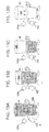
- Figs. 1A to 1F are perspective views illustrating different components of one configuration of a dialysis system employing the embodiments discussed herein.
- Figs. 2A to 2F are perspective views illustrating different components of another configuration of a dialysis system employing the embodiments discussed herein.
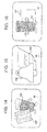
- Figs. 3A to 3E are perspective views illustrating different components of a further configuration of a dialysis system employing the embodiments discussed herein.
- Fig. 4 is a perspective view illustrating one example of a user interface for the dialysis system having a capacitance electromagnetic compliance ("EMC”) seal.
- EMC electromagnetic compliance
- Figs. 5 to 7 are schematic and elevation views showing one example of a user interface for a dialysis system employing the embodiments discussed herein.
- Figs. 8 and 9 are schematic views illustrating one example of a system employing the embodiments discussed herein having a low battery disconnect circuit.
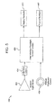
- Fig. 10 is a schematic view illustrating one example of a dialysis system employing the embodiments discussed herein having a silent alarm capability.
- Figs. 11A to 11D are machine screenshots illustrating an embodiment of a graphical depiction of a fill cycle of a dialysis system employing the embodiments discussed herein.
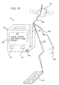
- Fig. 12 is a machine screenshot illustrating an embodiment of a graphical depiction of a dwell cycle of a dialysis system employing the embodiments discussed herein.
- Figs. 13A to 13D are machine screenshots illustrating an embodiment of a graphical depiction of a drain cycle of a dialysis system employing the embodiments discussed herein.
- Fig. 14 is a machine screenshot illustrating an embodiment of a graphical depiction offering treatment information for a dialysis system employing the embodiments discussed herein.
- Fig. 15 is a machine screenshot illustrating an embodiment of a graphical depiction offering alarm information for a dialysis system employing the embodiments discussed herein.
- Fig. 16 is a machine screenshot illustrating an embodiment of a graphical depiction offering patient information for a dialysis system employing the embodiments discussed herein.
- Fig. 17 is a machine screenshot illustrating an embodiment of a graphical depiction allowing the patient to change graphics/color settings in a dialysis system employing the embodiments discussed herein.
- Fig. 18 is a machine screenshot illustrating an embodiment of a graphical depiction allowing the patient to change alarm settings in a dialysis system employing the embodiments discussed herein.
- Fig. 19 is a machine screenshot illustrating an embodiment of a graphical depiction allowing the patient to change alarm settings in a dialysis system employing the embodiments discussed herein.
- Fig. 20 is a machine screenshot illustrating an embodiment of a graphical depiction signifying that therapy has been successful for a dialysis system employing the embodiments discussed herein.
- Fig. 21 is a machine screenshot illustrating an embodiment of a graphical depiction signifying that the machine has gone into a standby mode for a dialysis system employing the embodiments discussed herein.
- inventions described herein relate to medical fluid delivery systems that employ a pump, such as a peristaltic pump.
- a pump such as a peristaltic pump.
- systems, methods and apparatuses for cassette-based dialysis therapies including but not limited to hemodialysis, hemofiltration, hemodiafiltration, any type of continuous renal replacement therapy ("CRRT"), congestive heart failure treatment, CAPD, APD (including tidal modalities) and CFPD are disclosed.
- the cassette is disposable and typically discarded after a single use or therapy, reducing risks associated with contamination.
- a first configuration for the components of system 10 is illustrated by configuration 350.
- the pumping technology used for system 10 is a peristaltic pump. It is expressly contemplated, however, that many features and embodiments discusses herein can be used with peristaltic pumps, volumetric pumps, pumps operated pneumatically, pumps operated mechanically, pumps operated hydraulically and any combination thereof.
- the component features discussed in connection configuration 350 and indeed in connection with configurations 370 and 390 shown in connection with Figs. 2A to 2F and 3A to 3F are applicable to any of the different types of pumping technologies just previously described. Indeed, while cassette 50 is shown in connection with each of configuration 350, 370 and 390.
- configuration 350 of system 10 includes supply bags, 14, 16, and 22 and drain bag 24. Those bags are connected fluidly to machine or unit 60 via lines 28, 54, 20 and 32, respectfully, as seen in Fig. 1C additionally.
- Fig. 1A further illustrates that configuration 350 of system 10 includes an organizational mat 352, which is shown and discussed in more detail in connection with Fig. 1F .
- Fig. 1A further illustrates that configuration 350 can be placed partly on a desk or nightstand, with drain bag 24 being placed on the floor.
- supply bags 14, 16 and 22 and cassette 50 are loaded and maintained in an at least substantially horizontal configuration.
- unit 60 is a single integrated device, which includes a horizontal front drawer 354, the back of which curves vertically, so that a portion of cassette 50 is turned vertically for air separation purposes.
- Cassette 50 and heater bag 356, shown in more detail in connection with Fig. 1C are loaded via drawer 354 simultaneously into unit 60.
- Drawer 354 also aids in organizing cassette 50 and heater bag 356 to aid the patient in aligning, inserting and removing those items.
- the identification of the separate lines 28, 54, 20 and 32 is also shown on drawer 354, so that the patient can match corresponding indicia on the lines with the markings on drawer 354 for proper cassette installation.
- display 66 of machine or unit 60 is tilted at an angle of about forty-five degrees to about sixty degrees from vertical for ready viewing. Other angles could also be used.
- Unit 60 also includes controls 62 and 64, which can be off-screen controls, such as membrane switches, or on-screen controls, such as a touch screen overlay.
- the disposable set includes cassette 50 and separate heater bag 356, which are connected together via heater tubes.
- heater 38 is located inside machine 60.
- unit 60 cooperates with drawer 354 to turn a portion of heater bag 356 upwards for air separation.
- heater bag 356 is loaded first via drawer 354 into unit 60.
- the distill or free end of heater bag 356 is turned upward. That end may contain a vent or a filter, such as a hydrophobic membrane, which enables air escaping from the fluid in the heating pathway to collect at the vertical upper end of heater bag 356 and to eventually be vented through such a vent or filter.
- the disposable set includes a tubing organizer 358, which can be placed on the table or night stand to further assist the loading of cassette 50 and heater bag 356.
- Organizer 358 holds supply lines 28, 54 and 20 next to one another. Those lines in an embodiment are tacked or otherwise held together, so that the patient knows that those lines are intended to be connected to supply bags 22, 16 and 14, respectively. Drain line 32 in an embodiment has a larger diameter hose than do supply lines 28, 54 and 20. This also helps the patient to keep the different lines straight in memory.
- cassette 50 and the lines connected to organizer 358 are loaded through the front of the unit 60, which places the tubes in an advantageous viewing area in front of the patient.
- the identification of supply lines 28, 54 and 20, drain line 32 and patient line 12 is further aided via identifying markings.
- clamps 360 located at the distil ends of supply lines 20, 54, and 28 and drain line 32 are color-coded.
- the clamps can have molded line identification or indicia.
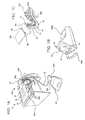
- Patient line 12 is identified via a connector 362 at its distil end.
- Connector 362 is removeably fixed to unit 60 as seen in Fig. 1A for priming.
- Unit 60 in one embodiment has a sensor, which senses whether connector 362 of patient line 12 is in proper position for priming before allowing therapy to begin.
- supply bags 14, 16 and 22 each include a port 364 and a vent 366.
- Vent 366 for example includes a filter or a membrane, such as a hydrophobic membrane, which enables gas to be purged from the supply bags.
- Ports 364 each include a seal, which is spiked via the ends of supply lines 28, 54 and 20. The seal eliminates the need for a clamp on supply bag port 364.
- Drain bag 24 also includes a port 364 and vent 366 as described above in connection with Fig. 1D .
- Bag 24 also includes a handle 368a, which aids in carrying bag 24 when it is full of spent fluid.
- a handle 368b is also provided with machine 60 as seen in connection with Fig. 1B for its ready transport.
- drain line 32 is provided with one or more apparatus, which enables the drain line to be fixed and held in a desired position.
- drain line 32 can be provided with a flexible, adhesive-backed strip 372, which may enables the drain line to be adhered to the desk or night stand, for example.
- Strip 372 in an embodiment slidably engages drain line 372 in frictional manner, so that strip 372 can be moved along drain line 32 to a desirable position.
- a clamp 374 which can be reusable, is provided so that drain line 32 can be clamped in a desirable position. Clamp 374 slides over drain line 32 and in embodiment can be positioned frictionally along different areas of the drain line.
- organizational mat 352 includes indicia 376a to 376e, which identifies the component at the illustrated location and where a component, such as the supply bag and drain bag, should be located.
- Mat 352 is reusable and made of a washable material.
- the indicia can further include written instructions, reminders and other useful information, such as color codes for the clamps and lines.
- configuration 370 is applicable to a dialysis system employing any of the different types of pumping technologies described herein.
- Fig. 2A shows configuration 370 using different shelves or levels of a desk, night stand, etc.
- Configuration 370 is advantageous in one respect because supply bags may be tucked out of the way, leaving unit or machine 60 as the primary component that the patient views.
- configuration 370 includes a bag stand 378, which orients supply bags 14, 16, and 22 in a position which allows gravity to help fluid travel from the supply bags to cassette 50.
- Stand 378 also organizes supply bags 14, 16 and 22 and includes or defines a plurality of notches or openings that hold the tubing or connectors, which extend from the supply bags.
- Bag stand 378 in one embodiment is made of vacuum-formed plastic or metal or is otherwise made of any suitable material.
- Figs. 2A and 2E illustrate that configuration 370 includes or uses a reusable drain container 24, which in the illustrated embodiment includes a rigid or semi-rigid housing 380.
- Housing 380 defines or includes a handle 368c.
- housing 380 is attached to wheels 382 which further aid in the transporting of the housing.
- Fig. 2E also shows that handle 368c is positioned so that housing 382 maybe tipped easily for drainage.
- an opening 384 of container 24 positioned so as to be located at the bottom of housing 380 when it is tipped over.
- Housing 380 of reusable drain container 24 includes a reusable cap 386, which when tightened on to mating threads of housing 380 compresses a ferral or other type of compressible apparatus or seal, located at the end of line 32, into a mating connector located or defined by housing 380.
- Fig. 2B illustrates unit or machine 60 in more detail.
- unit 60 of configuration 370 is a single integrated machine in the illustrated embodiment.
- Cassette 50 is loaded into unit 60 horizontally as illustrated.
- Supply and drain tubes again enter device 60 from the front for easy access.
- Video monitor 66 is hinged so that it maybe adjusted to a suitable angle relative to a table or nightstand on which it is placed, while closing to form a compact and portable unit.
- Rotatable monitor 66 operates in conjunction with controls 62 and 64, which again can be off-screen input devices (e.g., membrane switches) or on-screen input devices that use a touch screen overlay.
- Unit 60 can also have a handle (not illustrated) or be provided with a bag or carrying case (not illustrated) for ready transport.
- Cassette 50 includes an integrated fluid heating pathway 388.
- Integrated fluid heating pathway 388 can be a spiral path, which communicates with pathways located within the valve portion of cassette 50, such that to-and from-heater ports are not needed.
- Fluid heating pathway 388 operates with a heater 38 located within dialysis unit 60.
- patient line 12 and drain line 32 are preattached to ports of cassette 50.
- Drain line 32 can again have a larger diameter than patient line 12 for reasons discussed above.
- Cassette 50 also has fluid connector or ports 392, which connect to supply lines 20, 54, and 28.
- the supply lines or pigtails are preattached to supply bags, 14, 16 and 22, respectfully.
- patient line connector 362 located at the end of patient line 12 is pre-clipped or fastened to cassette 50 to orient the patient connector in proper position for priming. Further, drain line 32 and patient line 12 are coiled, so that cassette 50 can be moved more easily.
- Clamps 360 located at the ends of drain line 32 and supply lines 28, 54 and 20 can be color-coded as discussed above in connection with configuration 350. In an embodiment, connectors located at the ends of supply lines 28, 54 and 20 match with colors of luer connectors or ports 392 on cassette 50.
- Configuration 390 includes a dialysis machine or unit 60, having input devices 62 and 64 and a display device 66, including each of the alternative embodiments discussed above regarding those components.
- configuration 390 is provided with an APD night stand 394.
- a bottom drawer opening 396a receives a tray 398a.
- Tray 398a holds drain bag 24.
- drain bag or container 24 is placed in a tray 398a, which is then slid into bottom opening 396a.
- a middle tray 398b holds supply bags 14, 16 and 22 and cassette 50 in a middle opening 396b.
- Tray 398b is shown in more detail in connection with Fig. 3D .
- Top drawer 398c located in top opening 396c can be used for extra supplies for example. Drain container 24 can be pre-attached to cassette 50 or reusable as discussed above.
- the disposal portion of configuration 390 in one embodiment is integrated, so that the patient does not have to connect any solution bag lines 20, 28 and 54.
- patient line 12 and drain line 32 are pre-attached to cassette 50.
- patient setup merely requires the patient to place patient line connector 362 located at the end of patient line 12 on a hook or other attachment device 402 provided on the housing of unit 60 for prime.
- the patient connects drain line 32 to drain bag or container 24 and places container 24 in lower tray 398a.
- solution bags 14, 16 and 22, which are preattached to cassette 50 are loaded together as packaged in tray 398b.
- cassette 50 is monitored vertically, which can be advantageous from an air separation stand point.
- Tubing connected to cassette 50 enters unit 60 via the side of cassette 50 in the illustrated embodiment.
- Cassette 50 includes an integrated fluid heating pathway 386, similar to or the same as that for configuration 370. Drain line 32 can also have a larger diameter than the supply and patient lines.
- EMC Electromagnetic Compliance
- Display 400 includes a video display device 406.
- Video display device 406 is the component of machine display 400 that generates the various images, e.g., color or monochrome, seen by the patient.
- the metal case of video display device 406 makes intimate contact with an insulating dielectric film 408, which in turn makes intimate contact with an electrically conductive foam 410.
- One suitable display device 406 is provided for example, by Sharp Electronics, Color Thin Film Transistor ("TFT”) Liquid Crystal Display (“LCD”), model LQ057.
- TFT Color Thin Film Transistor
- LCD Liquid Crystal Display
- Suitable materials for insulative dielectric film 408 include polyester, polycarbonate and mylar. The material can have a thickness of about .003 inch (.075mm).
- One suitable material for electrically conductive foam 410 is made by Schlegel or Insul-Fab, IFT-CF2-3030FR.
- conductive foam 410 is pressed against conductive coated ridge 412, which is built into or formed with the non-conductive machine casing 414.
- Ridge 412 extends around the perimeter of opening 416 defined by machine casing 414, positions window 418 within casing 414 and creates a surface for the conductive coating of ridge 412 to contact conductive foam 410.
- Electrically conductive foam 410 has a larger outer dimension than does transparent window 418, which in an embodiment is an optically transparent, impact resistant, plastic piece. Accordingly, the outer edges of conductive foam 410 extend beyond window 418 and thereby contact metal ridge 412.
- Insulating dielectric 408 is the same size or wider in the inner and outer dimensions than is conductive foam 410. Therefore, insulating dielectric 408 prevents conductive foam 410 from contacting the metal case of display device 406. Insulating dielectric 408 thereby provides an electrically isolating barrier between conductive foam 410 and metal display 406.
- Conductive foam 410 contacts ridge 412 of machine casing 414 establishing an electrical connection.
- the conductive surfaces 410/412, the metal casing of display device 406 and the insulating dielectric material 408 sandwiched between those conductive surfaces form a capacitive electromagnetic compliance ("EMC") seal.
- a pressure sensitive adhesive (“PSA") 420 forms an environmental seal between transparent plastic window 418 and machine casing 414. That is, PSA 420 prevents dust and dirt from entering the inside of machine display 400 via opening 416.
- a mounting bracket (not shown) is fixed to machine casing 414, for example, via threaded couplers 422 welded to, heat staked or otherwise formed with machine casing 414. The bracket holds display device 406 and also compresses conductive foam 410 against display device 406 and ridge 412 of machine casing 414 to ensure good electrical contact between conductive foam 410 and the conductive coated ridge 412 of machine casing 414.
- Machine display 400 takes advantage of the metal ridge 412 of casing 414, which surrounds window 418, and the metal casing of display device 406.
- the resulting EMC seal prevents electromagnetic energy ("EMI") generated by the electronics within machine casing 414 from exiting or passing through the casing 414 or display device 406.
- the EMC seal also prevents EMI generated by outside electronic devices from entering the machine through the paths just described.
- the above-described apparatus eliminates the need for shielding the entire display opening with an electrically conductive window, which adds expense and can also adversely effect image quality.
- Machine display 400 eliminates the need for an electrically conductive window altogether and thus eliminates the disadvantages just described.
- User interface 430 includes an ambient light sensor 432, and interface circuit 434, control electronics/control function 436, a manual brightness button or other type of manual input 438, a display backlight 440 and a keypad backlight 442. Any one or more of the above-listed components can be provided on a printed circuit board (“PCB") located within dialysis machine 60.
- PCB printed circuit board
- interface circuit 434 is provided with sensor 432, located separately from the PCB.
- Ambient light sensor 432 senses an amount of ambient light in the room in which machine 60 is positioned and sends a signal such as a zero to ten volt or 4 to 20 milliamp variable output signal to the interface circuitry 434.
- Interface circuit 434 conditions the signal from the ambient light sensor to make it readable or useful to the control electronics/control function 436.
- the user interface backlight electronics 436 also receives a variable input signal from manual brightness input or rotary knob 438.
- input or knob 438 in one embodiment sets an initial brightness setting desired by the patient or operation.
- the signal from the manual brightness input 438 overrides the automatic backlighting provided via ambient sensor 432, interface circuit 434 and backlight electronics 436.
- rotary knob operates with directional arrows 446.
- the user interface backlight control function 436 outputs a variable amount of power to backlight display 440 and keypad backlight 442.
- the power to display backlight 440 can be the same as the power to keypad backlight 442, or the power to one of the backlights can be different, e.g., scaled by a factor, of the power to the other backlight.
- the keypad backlight may be controlled automatically to be slightly less bright than the display backlight 440 set initially via input 438 or vice versa.
- display backlight 440 can be controlled independently from keypad backlight 442.
- a second manual brightness control button, knob or controller can be provided, so that there is separate manual control of display backlight 440 and keypad backlight 442.
- the user or patient may want to set the display backlight to be more brightly lit, while the keypad backlight is set to be more dim or vice versa. Separate controls would also allow the user to turn one of the backlights off, while keeping the other on if desired.
- machine 60 (e.g., Figs. 1B , 2B and 3B ) will be operated in a varying ambient light environment because the machine may be used to perform dialysis at home and at any time during the day or night.
- the machine may be set up at night under normal room light conditions and perform therapy thereafter while a person sleeps with the lights off.
- Machine 60 at any time during therapy may need to warn the patient of an error or alarm and wake the patient potentially in a dark or dimly lit room.
- User interface 430 including automatically variable lighting automatically adjusts backlight intensity to compensate for changes in ambient light level so that such errors or alarms may be seen easily.
- Fig. 6 shows machine 60 operating with variable ambient light user interface 430.
- Ambient light sensor 432 is positioned to receive light impinging on machine 60.
- Light sensor 432 in an embodiment includes a photo receptor having a spectral response approximately that of the human eye, such as an LX1970 Visible Light Sensor provided by Microsemi Corporation, Garden Grove, CA. This sensor includes processing that provides a photopic light wavelength response curve that nearly duplicates that of the human eye.
- Control function 436 shown in Fig. 5 sets the backlight brightness 440 and 442 to the level set by the user and modifies the backlight in response to changing ambient light levels. For example, control function 436 can be configured so that an increase in ambient results in a corresponding increase in backlight intensity 440 and 442.
- Backlight control function 436 also compensates for any non-linearity of ambient light sensing.
- Backlight control function/electronics 436 can be a dedicated analog circuit, a dedicated digital circuit (such as a microcontroller), hybrid of both or be a functional element of a shared-embedded application processor. The function may also be implemented on an application specific integrated circuit ("ASIC").
- ASIC application specific integrated circuit
- the patient adjusts the ambient light setting via adjustment device 438, which includes a dial or knob for example.
- Device 438 controls a variable electrical output signal to backlight control function 436.
- Function 436 can be set to time-out after a period of non-adjustment, following a period of adjustment or control 436 to know when the desired setting has been made.
- circuitry 434 waits a period of time after the change to know that the change has been set. After this amount of time, control function/electronics 436 is set to assume that the desired backlight setting has been made.
- the setting can be made in any ambient condition.
- Control function/electronics 436 is configured to modify its output if the ambient conditions change, so that the overall backlight brightness level stays at the level set by the user. For example, if the patient sets a desired level during normal lighting conditions to a high backlit level and then night falls or the patient turns out room lights, electronics 436 would decrease the power to backlights 440 and 442 and maintain the relative brightness between the backlights 440 and 442 and the ambient light.
- a fixed level is adjustable after which circuitry 434 adjusts the backlight 440 and 442 to achieve or maintain that setting made by the patient.
- manual control or rotary knob 438 overrides an automatic, e.g., optimized setting made in software in which power is adjusted based on ambient light compared to the automatic setting.
- control function 436 is configured to compensate for the human eye's change in sensitivity due to ambient light levels integrated over time. As is known, the longer a person resides in the dark, the more sensitive the person's eye becomes. This phenomenon is sometimes termed as "dark adaptation" or "unaided night vision.” In this alternative embodiment, control function 436 would gradually reduce power to one or both of display backlight 440 and keypad backlight 442 over time and over a steady ambient light reading via sensor 432. This feature in an embodiment is performed only when control function 436 determines that it is dark enough to do so, such as at a particular ambient light, read from sensor 442, or lower.
- buttons 62a to 62d include buttons that are visible to the user, such as buttons 62a to 62d.
- User interface 430 also includes "hidden" buttons or inputs 64a and 64b.
- visible buttons 62a to 62d are three dimensional and raised to allow the patient to have enhanced finger traction and feel and for ease in locating a desired function. Buttons 62a to 62d provide tactile feedback when pressed.
- Each visible button 62a to 62d includes a three dimensional icon or indicia, which can be raised or inset so that a visually impaired person can identify a particular button through touch alone.
- Visible buttons 62a to 62d in an embodiment are color-coded or otherwise unique visually and/or tactily to further aid in their identification.
- each visible button 62a to 62d is backlit individually, wherein control function 436 of Fig. 5 can be configured to light only buttons which are currently operational.
- Hidden buttons 64a and 64b are provided behind front panel 428. Inputs 64a and 64b are accordingly shown in phantom. Front panel 428, however, may include indicia 444 that mark the areas of hidden buttons 64a and 64b. The patient presses icons 444 displayed on front panel 428 to activate hidden buttons 64a and 64b. Hidden buttons 64a and 64b can also provide tactile feedback through front panel 428 to inform the patient that the hidden button is being activated. Further, the patient can view changes occurring on video monitor 66 to receive such feedback and recognition. Hidden buttons 64a and 64b are advantageous for certain applications, including but not limited to nurse mode or service mode buttons or other buttons that are not used typically by the patient but used instead by clinicians or service personnel.
- user interface 430 can have any suitable number of visible and hidden buttons, which can be push type buttons, rotary knobs, such as rotary knob 438, toggle switches, maintained or momentary buttons, sliding input devices, and any suitable combination thereof.
- electromechanical buttons 62 (referring collectively to button 62a to 62d) and hidden buttons 64 (referring collectively to buttons 64a and 64b) can instead be provided on a touch screen overlay, which operates with video screen 66. It is advantageous to use the electromechanical configuration in one respect because the electromechanical buttons allow for the buttons to be three-dimensional, which enhances tactile feedback and recognition.
- LED board 426 shows different patterns for keypad backlighting 442 (442a to 442f) discussed above in connection with Fig. 5 .
- LED board 426 includes backlight pattern 442a operable with visible button 62a ( Fig. 6 ), backlight pattern 442b operable with visible button 62b ( Fig. 6 ), backlight pattern 442c operable with visible button 62c ( Fig. 6 ), backlight pattern 442d operable with rotary knob 438 ( Fig. 6 ), backlight pattern 442e operable with directional arrows 446 ( Fig.
- Patterns 442a to 442f are arranged as desired to provide a desired amount and spacing of backlighting behind buttons 62 (62a to 62d) and control knob 438.
- LED arrangements 442a to 442f can be lit individually, so that only active buttons are lit for example. This can help in machine setup and operation to guide the patient through different screens of therapy.
- circuit 470 illustrates one embodiment of a low battery disconnect circuit used with the electronics and user interface of system 10.
- Circuit 470 is located within control unit 60 (e.g., Figs. 1B , 2B and 3B ) and in an embodiment is provided on a printed circuit board, such as a delegate circuit board, which communicates with a supervisory PCB.
- Circuit 470 provides back-up power to machine 60 in an event that the main power source is interrupted. When the back-up power is used its output voltage level gradually declines over time as is known.
- the electronics driven by the battery back-up however need a steady voltage to operate reliably.
- a voltage regulator can be used to regulate the voltage at a steady level.
- Circuit 470 enables the disconnect point to be safely near the point of loss of voltage regulation. Accordingly, circuit 470 lengthens the amount of time that machine 60 can run on battery back-up.
- Circuit 470 includes a battery 472, a metal oxide semiconductor field effect transistor ("MOSFET”) 474, a voltage regulator 476, a voltage comparator 478, which receives a reference voltage 480, a regulated voltage output 482 and system ground 484. A negative terminal of battery 472, the voltage regulator 476 and the regulated voltage output 482 are all referenced to system ground 484.
- MOSFET metal oxide semiconductor field effect transistor
- Voltage regulator 476 receives a disable input 486a from voltage comparator 478 and a feedback input 486b from the source 488 of MOSFET 474. Regulator 476 also provides a voltage output 494 to the gate 490 of MOSFET 474 as well as to a positive terminal of voltage comparator 478.
- One suitable voltage regulator 476 is provided by Micrel Semiconductor Inc, San Jose, CA, part # MIC 5158, which is used in combination with a latch (not illustrated) that latches the disabled state.
- the positive terminal of battery 472 is connected electrically to the drain 492 of MOSFET 474.
- Circuit 470 takes advantage of an inherent characteristic MOSFET 474, which is an on-resistance versus gate voltage characteristic.
- Fig. 9 illustrates this characteristic.
- the characteristic is as follows.
- the voltage of battery 472 needs to be higher than the regulated output 494 of voltage regulator 476 to provide a linear regulator typology.
- the starting voltage of battery 472 can be six VDC, while the regulated output 494 is five VDC.
- the initial fully charged battery 472 can actually have a voltage of 6.1 VDC, for example.
- a voltage reference 480 supplied to the negative terminal of voltage comparator 478 in this example could be five VDC.
- Regulator 494 compares feedback voltage 486b to the voltage reference and adjusts its output 494 to gate 490 of MOSFET 474 so that the regulated output 482 is five VDC.
- VDS voltage drop
- the minimum achievable RDS for MOSFET 474 is about .02 Ohm.
- Regulator 476 is chosen such that it can drive VGS to at least 15 VDC, so that RDS can reach .02 Ohm according to Fig. 10 . If it is assumed again that the load driven by regulated output voltage 482 is one Amp, then for example VDS is .02 VDC at the minimum RDS of MOSFET 474 of .02 Ohm. In the example, the lowest voltage that battery 472 could provide to yield a regulated output voltage at 482 would therefore be 5.02 VDC.
- Reference voltage 480 for comparator 478 is set in one embodiment to 12 VDC.
- Circuit 470 accordingly provides topology that allows for lower tolerances and therefore lower precision and thus lower cost parts to be used in a safe and reliable circuit. It should be appreciated that even if the actual to theoretical low voltage output varies by plus or minus 25%, the resulting disconnect threshold varies by less than 5 millivolts. It should also be appreciated therefore that circuit 470 eliminates the need for a precision comparator function and safety margin, which has been used in the past to ensure that the threshold does not drop below the level at which regulation can be maintained. Adding a safety margin means that the nominal threshold voltage is moved higher, which results in a disconnected or battery voltage higher than that achievable with a topology of circuit 470. Disconnecting at a higher voltage means less time available to operate on battery back-up.
- the output of comparator 478 is used to trigger an interrupt to one or more processors of system 10, trigger a delay circuit (not illustrated) and have the output of the delay circuit trigger the shutdown of system 10.
- This approach signals to the one or more processor that power is to be disconnected shortly, giving the processor an opportunity to prepare for shutdown of system 10.
- the system could send an alarm to the patient, close one or more valve, ramp down one or more pump and record the status of therapy (such as the amount of fluid pumped per current cycle, amount of ultrafiltrate removed, etc.) and perform any other safety measure needed to prepare for shutdown.
- circuit 470 or the alternative interrupt circuit can notify a processor whenever a switch to battery back-up occurs, wherein the processor has the further capability to shut off power.
- circuit 470 or the alternative interrupt circuit can provide a back-up shut-off circuit in case the processor fails to shut itself off.
- a second comparator is provided having a voltage threshold less than that of comparator 478.
- the lower threshold voltage second comparator generates a processor interrupt signal when VGS becomes more positive than the threshold voltage.
- the higher threshold voltage of comparator 478 causes the system to be shut down when VGS becomes more positive than the higher threshold voltage. This causes a time delay.
- Fig. 10 one embodiment of system 10 having a silent alarm capability is illustrated.
- machine or unit 60 of system 10 e.g., Figs. 1A , 2A and 3A
- unit 60 may have to be located near other sleeping people who do not need to be awoken upon an alarm condition.
- the patient and/or patient's spouse can be hearing impaired or deaf and not be able to respond to an audible alarm from unit 60 of system 10.
- the silent alarm capability of system 10 solves these dilemmas.
- Fig. 10 shows the machine 60, which is configured similar to that shown in connection with Fig. 3B . It should be appreciated, however, that the silent alarm capability can be provided with any of the machines 60 described herein for system 10.
- Machine 60 houses a transmitter 500.
- One suitable transmitter 500 is provided by Harris Corporation SC-DOT1003-1 transmitter.
- Another suitable transmitter is an Alert Master Model 6000, part number AMER-AM 6000.
- transmitter 500 is microprocessor controlled.
- the microprocessor in an embodiment is provided on a safety controller or safety PCB, which operates with a supervisory microprocessor. The integration of transmitter 500 and microprocessor control helps to prevent false alarms because the microprocessor decides when transmitter 500 should send signal 502.
- Transmitter 500 transmits a radio frequency ("RF"), microwave, ultrasonic or infrared signal 502, which can be received by one or more remote receiver.
- the remote receiver can be a remote alarm, headset or computer 504, which generates a visual or audible alarm in a place located remotely from machine 60.
- Alarm 504 alerts a caregiver or relative that machine 60 of system 10 is experiencing an alarm condition.
- Video monitor 66 of machine 60 posts an alarm message 506, which can (i) describe the nature of the alarm and/or (ii) provide a suggested course of corrected action.
- Signal 502 can be continuous, e.g., for three seconds, or pulsed as desired.
- transmitter 500 is a local wireless paging system that sends its signal 502 to a remote pager or cellphone 508.
- Pager or cellphone 508 is worn by a caregiver or relative. The pager responds to signal 502 in a known manner, alerting the caregiver or relative to proceed to machine 60 and observe visual message 506.
- transmitter 500 sends signal 502 to a bed shaker 510.
- a bed shaker 510 is provided by Harris Communications Super-Shaker Model SA-SS120V, 120VAC.
- DC Model is SA-SS12V.
- Bed shaker 510 is placed beneath the patient or is otherwise coupled to the patient's bed, so that the patient is awakened upon an alarm. This can be done so as not to wake other people nearby.
- signal 502 can be sent to any combination of remote alarm 504, pager 508 and/or bed shaker 510.
- machine 60 can be configured with one or more speakers 512.
- Speakers 512 provide an audible alarm at machine 60, which can be made in lieu of or in addition to the signaling of the remote devices.
- Speakers 512 can alternatively provide an audible version of message 506, which audibly tells the patient, caregiver or relative what to do to correct the current alarm condition.
- signal 502 can be sent to remote alarm 504 or pager 508, alerting a person to come to machine 60, at which point the person hears an audible message from speaker 512 informing the person of the nature of the alarm and likely corrective action.
- the transmitter 500 exist alternatively externally to machine 60 and its display 66. This is done via an external interface connection through machine 60.
- the interface of machine 60 provides a polar/binary signal, ON/OFF signal or data stream interface, such as serial or parallel interface, depending upon the type of remote transmitter 500 used.
- FIGs. 11A to 11G screen shots of video monitor 66 of dialysis machine 60 of system 10 (e.g., Figs. 1A , 2A and 3A ) illustrate a fill cycle, such as a PD fill cycle graphically via a character 520.
- a fill cycle such as a PD fill cycle graphically via a character 520.
- character 520 is used throughout the therapy, to provide the patient with a consistent and familiar treatment display.
- a character 520 is shown as an animated drinking glass. It should be appreciated, however, that character 520 can have other suitable forms, shapes and/or indicia. In one embodiment, different characters or shape of a same character are provided as choices to the patient in a set-up mode. The character or shape chosen is used thereafter throughout the screens to display therapy progress and other information discussed below. The patient can change the character or shape at any time or in between treatments.
- character 520 has a friendly appearance, which also aids in relieving the stress of treatment. Character 520 adds a human element to therapy and provides useful information to the patient. It is contemplated that when such information is presented in a user-friendly format, the patient has a better probability of receiving and understanding the information.
- character 520 includes or has a therapy indicator 522, which in the illustrated embodiment is a hand extending from the body of glass 520, which points to or otherwise indicates which cycle of the therapy is currently underway.
- An up arrow 524a is provided initially to illustrate that the level of dialysis fluid is increasing, i.e., that a fill cycle is occurring.
- the water level in glass 520 on the other hand indicates a stage of a particular cycle.
- a fuller glass indicates that a later portion of the current cycle is taking place.
- the indicia of character 520 e.g., the face shown on the glass, is also consistent with the fact that system 10 is currently in an active, e.g., fill mode.
- a screen shot of video monitor 66 illustrates a dwell cycle, which occurs after the patient's peritoneum has been filled with a fill volume of dialysate.
- the dwell cycle is a relatively inactive cycle for system 10.
- Machine 60 is not pumping liquid to or from the patient.
- indicia 526 illustrates that the glass appears to be resting or sleeping.
- Up arrows 524a ( Figs. 11A to 11D ) are replaced by circular or dwell arrow 524b.
- Dwell arrow 524b indicates that the volume of fluid within the patient's peritoneum is currently not changing but is instead circulating or moving within the patient to remove waste and toxins.
- Glass 520 remains full of fluid during this period because the patient's peritoneum also remains full of fluid.
- character 520 animates a drain cycle.
- Animations for any of the cycles can be cartoon animations, video clips and any combination thereof.
- glass 520 is drained progressively in Figs. 13A to 13D to indicate that drain is taking place and how much of the drain cycle has occurred.
- Glass 520 is full at the beginning of the drain cycle in Fig. 13A .
- glass 520 is emptied completely, indicating the end of the drain cycle.
- Character indicator 522 and down arrow 524c both point downward, indicating fluid is leaving the patient, that is, indicating that machine 60 is currently in a drain cycle.
- any of the fill, dwell and drain cycle sequences can be accompanied by an elapsed time display, a time remaining display, an indication of whether the cycle, e.g., drain cycle is a first drain cycle, a second drain cycle, for example.
- the face of glass 520 also indicates that the glass is awake, e.g., that machine 60 of system 10 is in an active pumping cycle.
- the filling of glass 520 in any cycle occurs continuously, that is, the fill level is moving continuously albeit slowly during a particular cycle.
- the level changes after an increment of time, e.g., every ten seconds, every thirty seconds, every minute, every five minutes, etc.
- the level changes after an increment of volume, e.g., after every 10 millimeters pumped, 30 millimeters pumped, etc.
- the filling of glass 520 is also tied to other events that occur during treatment that may stop the filling. For example, if an alarm condition occurs in which pumping is stopped, video monitor 66 is configured to stop the display of the filling of glass 520.
- video monitor 66 is further configured to display other aspects of therapy, such as PD.
- character 520 is used in certain of these additional displays, while Fig. 15 illustrates that character 520 does not have to be displayed in each screen shot or for each feature of system 10.
- Fig. 14 illustrates a therapy report or therapy tracking screen in which character 520 holds a report 528 indicating that particular parameters of a previous treatment or therapy have been recorded.
- video monitor 66 operates with a touch screen overlay, in which case the patient can press therapy report 528 to review treatment information.
- Treatment information can include any potentially desirable information, such as, treatment time, volume delivered, fill times, dwell times, drain times, number of cycles, UF removed, average dialysate temperature, alarm information, etc.
- electromechanical inputs such as visible buttons 62 or hidden button 64 are used to recall information indicated by therapy report 528.
- Fig. 15 illustrates an alarm screen, which includes an alarm indicator 530 and an alarm report 532.
- the screen of Fig. 15 is displayed upon an alarm condition. If video monitor 66 operates with a touch screen overlay, either one or both of alarm indicator 530 and alarm report 532 can be touched to cause visual, audio or audiovisual alarm information to be given to the patient.
- the screen of Fig. 15 is shown at the end of treatment so that the patient can review a separate alarm report 532 to learn of any alarm conditions that occurred during the previous therapy or to learn of any alarms that have occurred over recent therapies, such as over the last week or month.
- video monitor 66 shows a patient information screen.
- character 520 is shown in combination with a file or folder 534, which represents a patient file or patient history.
- file 534 can itself be selected to show patient history, treatment parameters, background information and any other desirable patient-specific information. Otherwise, electromechanical inputs are used.
- the screens of Figs. 14 to 16 are sub-screens obtained selectively via a main screen or supervisiory sub-screen.
- Sub-screen selection can be done via a touch screen input or via electromechanical input, such as a scrolling input device that enables the patient to scroll through the icons representing the different screens (e.g., characters 520 in different settings) before selecting one of the icons to display the selected screen.
- FIG. 17 shows different screen shots of video monitor 66 in combination with an up and down arrow 536.
- Up/down arrow 536 indicates that corresponding settings can be changed for a particular function indicated by its associated icon 520, 530 or 538.
- Fig. 17 for example shows glass 520, which if pressed allows the user to change characters, e.g., from a glass to a person, color of the character, e.g., blue to red, or shape of the character, e.g., glass as shown to a mug, for example.
- any of the screens discussed herein can be associated with a touch screen overlay, which communicates with a touch screen controller, which in turn communicates directly or indirectly with a supervisory processor, controller or printed circuit board.
- glass 520 and arrow 536 can correspond to selectable areas or the touch screen.
- membrane switches or other types of electromechanical input devices are provided to enable the user to interact with glass 520 and arrow 536.
- Fig. 18 shows arrow 536 operable with alarm 530.
- This screen enables the patient to change (as indicated by up and down arrow 536) the alarm settings.
- Alarm 530 can be colored yellow or red or otherwise brightly to indicate that the function is significant or to caution or warn the patient of a particular condition.
- Fig. 19 shows arrow 536 operable with a control panel 538. This screen allows the operator to change instrument settings, such as, volume settings, brightness settings and other user preferences relating to the operation of the dialysis machine.
- video monitor 66 illustrates character 520 at the end of therapy or cycle.
- Fig. 20 illustrates a therapy successfully completed screen.
- character 520 and character indicator 522 indicate that the previous treatment or treatment cycle has been completed successfully.
- Fig. 21 shows character 520 in a rest or sleep mode.
- character 520 is indicating that the machine, while powered, is in a shut-down or dormant mode, in which therapy has ended or is in a paused or waiting state for a task to be completed or command to be entered..
- Character 520 is shown above displaying parameters for a PD system.
- character 520 is used in a blood filtering dialysis therapy, such as, HD, HF or HDF.
- character 520 can indicate ultrafiltration and the percentage of a prescribed amount of ultrafiltrate that has been removed at a certain point during treatment.
Landscapes
- Health & Medical Sciences (AREA)
- Heart & Thoracic Surgery (AREA)
- Urology & Nephrology (AREA)
- Emergency Medicine (AREA)
- Engineering & Computer Science (AREA)
- Vascular Medicine (AREA)
- Anesthesiology (AREA)
- Biomedical Technology (AREA)
- Hematology (AREA)
- Life Sciences & Earth Sciences (AREA)
- Animal Behavior & Ethology (AREA)
- General Health & Medical Sciences (AREA)
- Public Health (AREA)
- Veterinary Medicine (AREA)
- Power Engineering (AREA)
- Emergency Management (AREA)
- Business, Economics & Management (AREA)
- External Artificial Organs (AREA)
Abstract
Description
- In general, the present disclosure relates to medical fluid delivery systems that employ a pumping cassette. In particular, the present disclosure provides systems, methods and apparatuses for cassette-based dialysis medical fluid therapies, including but not limited to those using peristaltic pumps and diaphragm pumps.
- Due to various causes, a person's renal system can fail. Renal failure produces several physiological derangements. The balance of water, minerals and the excretion of daily metabolic load is no longer possible and toxic end products of nitrogen metabolism (urea, creatinine, uric acid and others) can accumulate in blood and tissue.
- Kidney failure and reduced kidney function have been treated with dialysis. Dialysis removes waste, toxins and excess water from the body that would otherwise have been removed by normal functioning kidneys. Dialysis treatment for replacement of kidney functions is critical to many people because the treatment is life-saving.
- Hemodialysis and peritoneal dialysis are two types of dialysis therapies used commonly to treat loss of kidney function. Hemodialysis treatment utilizes the patient's blood to remove waste, toxins and excess water from the patient. The patient is connected to a hemodialysis machine and the patient's blood is pumped through the machine. Catheters are inserted into the patient's veins and arteries so that blood can flow to and from the hemodialysis machine. The blood passes through a dialyzer of the machine, which removes waste, toxins and excess water from the blood. The cleaned blood is returned to the patient. A large amount of dialysate, for example about 120 liters, is consumed to dialyze the blood during a single hemodialysis therapy. Hemodialysis treatment lasts several hours and is generally performed in a treatment center about three or four times per week.
- Peritoneal dialysis uses a dialysis solution, or "dialysate," which is infused into a patient's peritoneal cavity via a catheter. The dialysate contacts the peritoneal membrane of the peritoneal cavity. Waste, toxins and excess water pass from the patient's bloodstream, through the peritoneal membrane and into the dialysate due to diffusion and osmosis, i.e., an osmotic gradient occurs across the membrane. The spent dialysate is drained from the patient, removing waste, toxins and excess water from the patient. This cycle is repeated.
- There are various types of peritoneal dialysis therapies, including continuous ambulatory peritoneal dialysis ("CAPD"), automated peritoneal dialysis ("APD"), tidal flow APD and continuous flow peritoneal dialysis ("CFPD"). CAPD is a manual dialysis treatment. The patient manually connects an implanted catheter to a drain, allowing spent dialysate fluid to drain from the peritoneal cavity. The patient then connects the catheter to a bag of fresh dialysate, infusing fresh dialysate through the catheter and into the patient. The patient disconnects the catheter from the fresh dialysate bag and allows the dialysate to dwell within the peritoneal cavity, wherein the transfer of waste, toxins and excess water takes place. After a dwell period, the patient repeats the manual dialysis procedure, for example, four times per day, each treatment lasting about an hour. Manual peritoneal dialysis requires a significant amount of time and effort from the patient, leaving ample room for improvement.
- Automated peritoneal dialysis ("APD") is similar to CAPD in that the dialysis treatment includes drain, fill, and dwell cycles. APD machines, however, perform the cycles automatically, typically while the patient sleeps. APD machines free patients from having to manually perform the treatment cycles and from having to transport supplies during the day. APD machines connect fluidly to an implanted catheter, to a source or bag of fresh dialysate and to a fluid drain. APD machines pump fresh dialysate from a dialysate source, through the catheter, into the patient's peritoneal cavity, and allow the dialysate to dwell within the cavity, and allow the transfer of waste, toxins and excess water to take place. The source can be multiple sterile dialysate solution bags.
- APD machines pump spent dialysate from the peritoneal cavity, though the catheter, to the drain. As with the manual process, several drain, fill and dwell cycles occur during APD. A "last fill" occurs at the end of CAPD and APD, which remains in the peritoneal cavity of the patient until the next treatment.
- Both CAPD and APD are batch type systems that send spent dialysis fluid to a drain. Tidal flow systems are modified batch systems. With tidal flow, instead of removing all of the fluid from the patient over a longer period of time, a portion of the fluid is removed and replaced after smaller increments of time.
- Continuous flow, or CFPD, systems clean or regenerate spent dialysate instead of discarding it. The systems pump fluid into and out of the patient, through a loop. Dialysate flows into the peritoneal cavity through one catheter lumen and out another catheter lumen. The fluid exiting the patient passes through a reconstitution device that removes waste from the dialysate, e.g., via a urea removal column that employs urease to enzymatically convert urea into ammonia. The ammonia is then removed from the dialysate by adsorption prior to reintroduction of the dialysate into the peritoneal cavity. Additional sensors are employed to monitor the removal of ammonia. CFPD systems are typically more complicated than batch systems.
- Hemodialysis, APD (including tidal flow) and CFPD systems can employ a pumping cassette. The pumping cassette typically includes a flexible membrane that is moved mechanically to push and pull dialysis fluid out of and into, respectively, the cassette. Certain known systems include flexible sheeting on one side of the cassette, while others include sheeting on both sides of the cassette. Positive and/or negative pressure can be used to operate the pumping cassettes.
- As described herein, the present disclosure provides a number of improvements to such fluid delivery systems.
- A first aspect of the embodiments described herein includes improved product configurations. Here, different parts of the cassette-based peritoneal dialysis system are configured advantageously, such as: (i) operational placement of the system; (ii) user interface configuration and orientation; (iii) disposable cassette loading; (iv) cassette/heater and bag/tube management; (v) solution bag configuration; (vi) drain bag configuration; and (vii) storage and supply organization.
- An second aspect of the embodiments described herein includes a capacitance electromagnetic compliance ("EMC") seal for the display of the user interface of the dialysis system. The seal as seen below does not cover the viewable portion of the display, improving light transmittance and image quality versus known seals.
- A third aspect of the embodiments described herein includes an elastomeric keypad for use with the display of the user interface of the dialysis system. The keypad, among other features, includes an ambient light sensor that provides a signal output, which is used to control adjustment of display brightness and contrast based on a change in ambient light.
- A fourth aspect of the embodiments described herein includes a low battery disconnect circuit for the dialysis system. The circuit allows the battery back-up disconnect voltage to be set closer to the regulated voltage, enabling the dialysis system to operate longer on battery back-up power.
- A fifth aspect of the embodiments described herein includes an improved silent alarm for the dialysis system. The silent alarm system, among other features, includes a transmitter that sends a signal to a remote alarming device, which can alert a caregiver to a dialysis system failure without disturbing the patent and/or people around the patent, who may be sleeping.
- A sixth aspect of the embodiments described herein includes a visual symbol or character shown on the display of the user interface of the dialysis system, which communicates pictorially ongoing happenings of the therapy, such as: (i) patient fill; (ii) solution dwell; (iii) patient drain; (iv) therapy status; (v) alarm status; (vi) patient history; (vii) therapy completed successfully; and (viii) system shut down.
- A first primary embodiment includes improved product configurations. Here, the cassette-based dialysis system can be configured to be placed on a patient's existing nightstand or be provided with its own nightstand. The instrument or actuator unit of the system can be configured to accept the disposable cassette horizontally or vertically. The display and user interface of the actuator unit may be integral to the actuator unit and for example be mounted at an upright angle or be rotatable and closeable with respect to the remainder of the actuator unit.
- It is also contemplated to arrange the disposable cassette, heater bag, supply bag and tubing in a variety of advantages configurations. In one implementation the disposable cassette is integrated to the heater bag. In another implementation, the heater bag is coupled to ports extending from the disposable cassette. The solution bags may be configured with any one or more of: (i) a spike seal that ensures a solution bag seal prior to pinching the solution bag; (ii) pre-attached tubing; and/or (iii) a delivery tray. The tubing may be configured with any one or more of: (i) the supply tubes tacked together; (ii) a larger diameter draw hose; (iii) the patient and/or drain line coiled; (iv) the patient and/or drain lines pre-attached to the cassette; (v) leur connections provided on the supply tubes for ready attachment to the supply bags; (vi) the patient tube pre-attached to the disposable cassette so as to be in proper orientation for operation with a primary sensor; (vii) clamps color-coded and/or configured with line identification.
- The drainage for the dialysis system may also be configured advantageously in a variety of ways. For example the drain tubes may be provided with adhesive bonding and/or a clamp to help secure the drain bag and/or the drain bag. The drain bag may be configured: (i) with a handle; (ii) to be reusable; (iii) to be a flexible bag or an at least semi-rigid container; (iv) to be a container with a handle oriented to easily tip the container and/or with wheels; and (v) to be pre-attached to the drain tube and/or the disposable cassette.
- The organization of the dialysis system is also configurable in a variety of ways advantageously. One implementation includes an organizational mat that prompts the patient to organize the fluid bags/containers properly and to gather the supplies needed. Another implementation provides a solution bag tray that orients the solution bags for optimum performance. Still a further implementation provides a nightstand, which holds any one or more of: (i) the actuator unit; (ii) additional supplies; (iii) solution/drain bag; (vi) disposable cassette; and (v) tubing.
- A second primary embodiment includes an improved display device, which employs a capacitance electromagnetic compliance ("EMC") seal. The display device includes an insulating dielectric material (e.g., mylar film) placed between the metal case of the display device or monitor and a conductive coating located on the housing of the dialysis machine. The metal case and metal coating are electrically isolated from each other. The dielectric material and the two conductive surfaces form a capacitor that prevents leakage of electromagnetic energy.
- A third primary embodiment includes an improved elastomeric keypad. The keypad, among other features, includes an ambient light sensor that provides a signal output that the dialysis system uses to adjust the brightness and contrast of the display based on the amount of ambient light sensed. The ambient light sensor is imbedded into or is otherwise secured by the machine housing such that at least a portion of the sensor is oriented to be able to gather ambient light. The sensor is connected with electronics to a backlight control function. The output of the backlight control function controls the brightness of the user interface display and keyboard backlighting. In one implementation, an increase in ambient light results in a corresponding increase in backlight intensity. Conversely, a decrease in ambient light results in a corresponding decrease in backlight intensity.
- A fourth primary embodiment includes a low battery disconnect circuit for use with the peritoneal dialysis machine. The cassette-based system includes a battery back-up power source. When the system is obtaining power from the battery back-up, the output voltage of the battery back-up gradually declines over time. The battery output is connected to a voltage regulator circuit that regulates the battery output to a constant level. As the battery voltage declines, a point can be reached in which the regulator can no longer hold the output voltage constant. The disconnect circuit serves to optimize this point to increase the life of the battery back-up power source.
- The regulator circuit includes a metal oxide field effect transistor ("MOSFET"). In the circuit, the MOSFET acts as a variable resistor according to its inherent on-resistance versus gate voltage characteristic. The regulator controller compares a feedback voltage at the source of the MOSFET to an internal voltage reference and adjusts the voltage at the gate of the MOSFET to produce a desired, regulated output voltage. As the battery voltage declines, the regulator controller increases the voltage at the gate of the MOSFET, which according to the on-resistance versus gate voltage characteristic decreases the drain to source resistance, reducing the voltage drop across the MOSFET, so as to maintain the MOSFET source pin at a desired regulated voltage. As described in detail below, the MOSFET regulator controller and the remainder of the circuit enable the disconnection of the battery to be made at a voltage very close to the regulated voltage, maximizing battery back-up time. The circuit prolongs the use of the battery back-up and enables more cost effective components to be used.
- In one implementation, a medical fluid machine includes an enclosure; and electronics located within the enclosure and operable to control delivery of the medical fluid, the electronics configured to be powered by an external electrical power source or a back-up battery, the electronics including a transistor in electrical communication with the battery, and a voltage regulator configured to vary a gate voltage at the transistor due to varying battery voltage and/or load current so as to maintain an at least substantially steady supply voltage to the load.
- In one implementation, the regulator is configured to accept as feedback the supply voltage and to vary the gate voltage to maintain the at least substantially steady supply voltage at a desired level.
- In one implementation, the electronics includes at least one of the following characteristics selected from the group consisting of: (i) the transistor being a low resistance metal oxide semiconductor field effect transistor; (ii) the battery being in electrical communication with a drain of the transistor; (iii) being in electrical communication with a source of the transistor; (iv) a negative side of the battery being connected electrically to system ground; (v) the regulator being connected electrically to system ground; and (vi) a supply voltage return to system ground.
- In one implementation, the electronics includes a voltage comparator configured to switch when the gate voltage becomes more positive than a threshold value, causing the gate voltage of the transistor to drop at least substantially to zero.
- In one implementation, the voltage comparator is connected electronically to the voltage regulator, the switch configured to disable the voltage regulator when the gate voltage becomes more positive than the threshold value, the disabling of the voltage regulator causing the gate voltage to drop at least substantially to zero.
- In one implementation, the voltage comparator is configured to trigger (i) an interrupt to a processor of the machine; and (ii) a time delay circuit configured to delay the dropping of the gate voltage to at least substantially zero, enabling the processor to prepare for shut-down.
- In one implementation, the voltage comparator a first voltage comparator and which includes a second voltage comparator having a second threshold voltage less than the first threshold voltage of the first voltage comparator, the second voltage comparator causing a processor interrupt signal when the gate voltage becomes more positive than the second threshold voltage, the first voltage comparator causing the machine to shut down when the gate voltage becomes more positive than the first threshold voltage.
- In one implementation, the machine includes a processor configured to receive a signal when a switch to the back-up battery occurs, the processor and the voltage comparator both capable of shutting-off power to the processor.
- In one implementation, a medical fluid machine includes: an enclosure; at least one medical fluid delivery component located inside the enclosure, the component capable of being powered by an external power source or a back-up battery; a transistor in electrical communication with the battery; and a regulator configured to: (i) receive as feedback a supply voltage, and (ii) vary a gate voltage at the transistor to maintain the supply voltage at least substantially at a desired level.
- A fifth primary embodiment includes a silent or remote alarm apparatus that operates with the cassette-based peritoneal dialysis system. The system contains speakers that can be used to sound audible alarms at the machines. The system also includes a transmitter that can be used alternatively to send a signal to a remote alerting device. The display of the machine shows a visual message detailing the type of the alarm and/or instructions for addressing the alarm. A receiving unit receives a signal sent by the transmitter and generates an audio, visual and/or physical (e.g., vibrating) alarming output to the patient or to a caregiver or hospital member located remotely with respect to the patient. The signal for example can be sent to a bed shaker that wakes only the person that needs to be awakened, e.g., the patient or caregiver. Family members or other patients in the room with the patient do not have to be awakened needlessly.
- In an sixth primary embodiment, the user interface displays a figure or character that shows the progress of a number of treatment steps for the dialysis treatment. In the embodiments illustrated herein, the display of the user interface displays a cartoon, video or other changeable image of a drinking glass. The glass is filled during fill, dwell and drain cycles. The filling of the glass in essence tracks the time or percentage of completeness of the particular cycle. The glass includes indicia indicating whether the cycle is a fill, dwell or drain cycle.
- The glass is non-imposing and provides a friendlier way to instruct the patient during therapy. The glass is incorporated into other aspects of peritoneal dialysis, such as alarm conditions, status reports, patient history, therapy completed successfully and system shut down.
- It is therefore an advantage of the embodiments described herein is to provide improved configurations for the components of a cassette-based dialysis system.
- Another advantage of the embodiments described herein to provide improvements to the user interface of the dialysis system, such as an improved display, an improved keypad, an improved alarming capability and an improved state of therapy and therapy feature indication.
- Yet a further advantage of the embodiments described herein is to provide an improved battery back-up feature for a cassette-based dialysis system.
- Additional features and advantages of the embodiments described herein are described in, and will be apparent from, the following Detailed Description of the Disclosure and the figures.
-
Figs. 1A to 1F are perspective views illustrating different components of one configuration of a dialysis system employing the embodiments discussed herein. -
Figs. 2A to 2F are perspective views illustrating different components of another configuration of a dialysis system employing the embodiments discussed herein. -
Figs. 3A to 3E are perspective views illustrating different components of a further configuration of a dialysis system employing the embodiments discussed herein. -
Fig. 4 is a perspective view illustrating one example of a user interface for the dialysis system having a capacitance electromagnetic compliance ("EMC") seal. -
Figs. 5 to 7 are schematic and elevation views showing one example of a user interface for a dialysis system employing the embodiments discussed herein. -
Figs. 8 and9 are schematic views illustrating one example of a system employing the embodiments discussed herein having a low battery disconnect circuit. -
Fig. 10 is a schematic view illustrating one example of a dialysis system employing the embodiments discussed herein having a silent alarm capability. -
Figs. 11A to 11D are machine screenshots illustrating an embodiment of a graphical depiction of a fill cycle of a dialysis system employing the embodiments discussed herein. -
Fig. 12 is a machine screenshot illustrating an embodiment of a graphical depiction of a dwell cycle of a dialysis system employing the embodiments discussed herein. -
Figs. 13A to 13D are machine screenshots illustrating an embodiment of a graphical depiction of a drain cycle of a dialysis system employing the embodiments discussed herein. -
Fig. 14 is a machine screenshot illustrating an embodiment of a graphical depiction offering treatment information for a dialysis system employing the embodiments discussed herein. -
Fig. 15 is a machine screenshot illustrating an embodiment of a graphical depiction offering alarm information for a dialysis system employing the embodiments discussed herein. -
Fig. 16 is a machine screenshot illustrating an embodiment of a graphical depiction offering patient information for a dialysis system employing the embodiments discussed herein. -
Fig. 17 is a machine screenshot illustrating an embodiment of a graphical depiction allowing the patient to change graphics/color settings in a dialysis system employing the embodiments discussed herein. -
Fig. 18 is a machine screenshot illustrating an embodiment of a graphical depiction allowing the patient to change alarm settings in a dialysis system employing the embodiments discussed herein. -
Fig. 19 is a machine screenshot illustrating an embodiment of a graphical depiction allowing the patient to change alarm settings in a dialysis system employing the embodiments discussed herein. -
Fig. 20 is a machine screenshot illustrating an embodiment of a graphical depiction signifying that therapy has been successful for a dialysis system employing the embodiments discussed herein. -
Fig. 21 is a machine screenshot illustrating an embodiment of a graphical depiction signifying that the machine has gone into a standby mode for a dialysis system employing the embodiments discussed herein. - The embodiments described herein relate to medical fluid delivery systems that employ a pump, such as a peristaltic pump. In particular, systems, methods and apparatuses for cassette-based dialysis therapies including but not limited to hemodialysis, hemofiltration, hemodiafiltration, any type of continuous renal replacement therapy ("CRRT"), congestive heart failure treatment, CAPD, APD (including tidal modalities) and CFPD are disclosed. The cassette is disposable and typically discarded after a single use or therapy, reducing risks associated with contamination.
- Referring now to
Figs. 1A to 1F a first configuration for the components ofsystem 10 is illustrated byconfiguration 350. As discussed herein, in one embodiment the pumping technology used forsystem 10 is a peristaltic pump. It is expressly contemplated, however, that many features and embodiments discusses herein can be used with peristaltic pumps, volumetric pumps, pumps operated pneumatically, pumps operated mechanically, pumps operated hydraulically and any combination thereof. The component features discussed inconnection configuration 350 and indeed in connection withconfigurations Figs. 2A to 2F and3A to 3F , respectfully, are applicable to any of the different types of pumping technologies just previously described. Indeed, whilecassette 50 is shown in connection with each ofconfiguration - As seen in
Fig. 1A ,configuration 350 ofsystem 10 includes supply bags, 14, 16, and 22 anddrain bag 24. Those bags are connected fluidly to machine orunit 60 vialines Fig. 1C additionally.Fig. 1A further illustrates thatconfiguration 350 ofsystem 10 includes anorganizational mat 352, which is shown and discussed in more detail in connection withFig. 1F .Fig. 1A further illustrates thatconfiguration 350 can be placed partly on a desk or nightstand, withdrain bag 24 being placed on the floor. In the illustrated embodiment,supply bags cassette 50 are loaded and maintained in an at least substantially horizontal configuration. - Referring now to
Fig. 1B , machine orunit 60 is illustrated in more detail. Here,unit 60 is a single integrated device, which includes a horizontalfront drawer 354, the back of which curves vertically, so that a portion ofcassette 50 is turned vertically for air separation purposes.Cassette 50 andheater bag 356, shown in more detail in connection withFig. 1C , are loaded viadrawer 354 simultaneously intounit 60.Drawer 354 also aids in organizingcassette 50 andheater bag 356 to aid the patient in aligning, inserting and removing those items. To that end, the identification of theseparate lines drawer 354, so that the patient can match corresponding indicia on the lines with the markings ondrawer 354 for proper cassette installation. In the illustrated embodiment, display 66 of machine orunit 60 is tilted at an angle of about forty-five degrees to about sixty degrees from vertical for ready viewing. Other angles could also be used.Unit 60 also includescontrols - Referring now to
Fig. 1C , the disposable, sterile, fluid carrying portion ofconfiguration 350 is illustrated. The disposable set includescassette 50 andseparate heater bag 356, which are connected together via heater tubes. Thus, inconfiguration 350, heater 38 is located insidemachine 60. As discussed above,unit 60 cooperates withdrawer 354 to turn a portion ofheater bag 356 upwards for air separation. In the illustrated embodiment,heater bag 356 is loaded first viadrawer 354 intounit 60. The distill or free end ofheater bag 356 is turned upward. That end may contain a vent or a filter, such as a hydrophobic membrane, which enables air escaping from the fluid in the heating pathway to collect at the vertical upper end ofheater bag 356 and to eventually be vented through such a vent or filter. - The disposable set includes a
tubing organizer 358, which can be placed on the table or night stand to further assist the loading ofcassette 50 andheater bag 356.Organizer 358 holdssupply lines bags Drain line 32 in an embodiment has a larger diameter hose than do supplylines configuration 350,cassette 50 and the lines connected toorganizer 358 are loaded through the front of theunit 60, which places the tubes in an advantageous viewing area in front of the patient. - The identification of
supply lines drain line 32 andpatient line 12 is further aided via identifying markings. For example, clamps 360 (Fig. 1C ) located at the distil ends ofsupply lines drain line 32 are color-coded. Furthermore, the clamps can have molded line identification or indicia.Patient line 12 is identified via aconnector 362 at its distil end.Connector 362 is removeably fixed tounit 60 as seen inFig. 1A for priming.Unit 60 in one embodiment has a sensor, which senses whetherconnector 362 ofpatient line 12 is in proper position for priming before allowing therapy to begin. - As seen in
Fig. 1D ,supply bags port 364 and avent 366. Vent 366 for example includes a filter or a membrane, such as a hydrophobic membrane, which enables gas to be purged from the supply bags.Ports 364 each include a seal, which is spiked via the ends ofsupply lines supply bag port 364. - Referring now to
Fig. 1E , an embodiment fordrain bag 24 is illustrated.Drain bag 24 also includes aport 364 and vent 366 as described above in connection withFig. 1D .Bag 24 also includes ahandle 368a, which aids in carryingbag 24 when it is full of spent fluid. Ahandle 368b is also provided withmachine 60 as seen in connection withFig. 1B for its ready transport. As seen inFig. 1E ,drain line 32 is provided with one or more apparatus, which enables the drain line to be fixed and held in a desired position. For example,drain line 32 can be provided with a flexible, adhesive-backedstrip 372, which may enables the drain line to be adhered to the desk or night stand, for example.Strip 372 in an embodiment slidably engagesdrain line 372 in frictional manner, so thatstrip 372 can be moved alongdrain line 32 to a desirable position. Additionally or alternatively, aclamp 374, which can be reusable, is provided so thatdrain line 32 can be clamped in a desirable position. Clamp 374 slides overdrain line 32 and in embodiment can be positioned frictionally along different areas of the drain line. - As seen in
Fig. 1F ,organizational mat 352 includesindicia 376a to 376e, which identifies the component at the illustrated location and where a component, such as the supply bag and drain bag, should be located.Mat 352 is reusable and made of a washable material. The indicia can further include written instructions, reminders and other useful information, such as color codes for the clamps and lines. - Referring now to
Figs. 2A to 2F , asecond configuration 370 forsystem 10 is illustrated. As before,configuration 370 is applicable to a dialysis system employing any of the different types of pumping technologies described herein.Fig. 2A showsconfiguration 370 using different shelves or levels of a desk, night stand, etc.Configuration 370 is advantageous in one respect because supply bags may be tucked out of the way, leaving unit ormachine 60 as the primary component that the patient views. As seen additionally inFig. 2F ,configuration 370 includes abag stand 378, which orientssupply bags cassette 50. Stand 378 also organizessupply bags Bag stand 378 in one embodiment is made of vacuum-formed plastic or metal or is otherwise made of any suitable material. -
Figs. 2A and2E illustrate thatconfiguration 370 includes or uses areusable drain container 24, which in the illustrated embodiment includes a rigid orsemi-rigid housing 380.Housing 380 defines or includes ahandle 368c. In the illustrated embodiment,housing 380 is attached towheels 382 which further aid in the transporting of the housing.Fig. 2E also shows thathandle 368c is positioned so thathousing 382 maybe tipped easily for drainage. To that end, anopening 384 ofcontainer 24 positioned so as to be located at the bottom ofhousing 380 when it is tipped over.Housing 380 ofreusable drain container 24 includes areusable cap 386, which when tightened on to mating threads ofhousing 380 compresses a ferral or other type of compressible apparatus or seal, located at the end ofline 32, into a mating connector located or defined byhousing 380. -
Fig. 2B illustrates unit ormachine 60 in more detail. As withunit 60 ofconfiguration 350,unit 60 ofconfiguration 370 is a single integrated machine in the illustrated embodiment.Cassette 50 is loaded intounit 60 horizontally as illustrated. Supply and drain tubes again enterdevice 60 from the front for easy access. Video monitor 66 is hinged so that it maybe adjusted to a suitable angle relative to a table or nightstand on which it is placed, while closing to form a compact and portable unit. Rotatable monitor 66 operates in conjunction withcontrols Unit 60 can also have a handle (not illustrated) or be provided with a bag or carrying case (not illustrated) for ready transport. - Referring now to
Fig. 2C cassette 50 is shown loaded intounit 60.Cassette 50 includes an integratedfluid heating pathway 388. Integratedfluid heating pathway 388 can be a spiral path, which communicates with pathways located within the valve portion ofcassette 50, such that to-and from-heater ports are not needed.Fluid heating pathway 388 operates with a heater 38 located withindialysis unit 60. - In the illustrated embodiment,
patient line 12 anddrain line 32 are preattached to ports ofcassette 50.Drain line 32 can again have a larger diameter thanpatient line 12 for reasons discussed above.Cassette 50 also has fluid connector orports 392, which connect to supplylines - As seen additionally in
Fig. 2C ,patient line connector 362 located at the end ofpatient line 12 is pre-clipped or fastened tocassette 50 to orient the patient connector in proper position for priming. Further,drain line 32 andpatient line 12 are coiled, so thatcassette 50 can be moved more easily.Clamps 360 located at the ends ofdrain line 32 andsupply lines configuration 350. In an embodiment, connectors located at the ends ofsupply lines ports 392 oncassette 50. - Referring now to
Figs. 3A to 3E , athird product configuration 390 is illustrated forsystem 10.Configuration 390 includes a dialysis machine orunit 60, havinginput devices display device 66, including each of the alternative embodiments discussed above regarding those components. As seen inFigs. 3A and3E ,configuration 390 is provided with anAPD night stand 394. InFig. 3E , abottom drawer opening 396a receives atray 398a.Tray 398a holdsdrain bag 24. In the illustrated embodiment, drain bag orcontainer 24 is placed in atray 398a, which is then slid intobottom opening 396a. Amiddle tray 398b holdssupply bags cassette 50 in amiddle opening 396b.Tray 398b is shown in more detail in connection withFig. 3D . Top drawer 398c located intop opening 396c can be used for extra supplies for example.Drain container 24 can be pre-attached tocassette 50 or reusable as discussed above. - As seen in
Figs. 3C and3D , the disposal portion ofconfiguration 390 in one embodiment is integrated, so that the patient does not have to connect anysolution bag lines patient line 12 anddrain line 32 are pre-attached tocassette 50. Here, patient setup merely requires the patient to placepatient line connector 362 located at the end ofpatient line 12 on a hook orother attachment device 402 provided on the housing ofunit 60 for prime. The patient connectsdrain line 32 to drain bag orcontainer 24 and placescontainer 24 inlower tray 398a. As seen inFig. 3D ,solution bags cassette 50 are loaded together as packaged intray 398b. Here, the patient pullscassette 50 fromtray 398b and places it into avertical slot 404 defined bymachine 60. Thus inconfiguration 390,cassette 50 is monitored vertically, which can be advantageous from an air separation stand point. Tubing connected tocassette 50 entersunit 60 via the side ofcassette 50 in the illustrated embodiment.Cassette 50 includes an integratedfluid heating pathway 386, similar to or the same as that forconfiguration 370.Drain line 32 can also have a larger diameter than the supply and patient lines. - Referring now to
Fig. 4 , one embodiment of a display usable with any of the machines or units 60 (e.g.,Figs. 1B ,2B and3B ) described herein is illustrated bymachine display 400.Display 400 includes avideo display device 406.Video display device 406 is the component ofmachine display 400 that generates the various images, e.g., color or monochrome, seen by the patient. The metal case ofvideo display device 406 makes intimate contact with an insulatingdielectric film 408, which in turn makes intimate contact with an electricallyconductive foam 410. Onesuitable display device 406 is provided for example, by Sharp Electronics, Color Thin Film Transistor ("TFT") Liquid Crystal Display ("LCD"), model LQ057. Suitable materials for insulativedielectric film 408 include polyester, polycarbonate and mylar. The material can have a thickness of about .003 inch (.075mm). One suitable material for electricallyconductive foam 410 is made by Schlegel or Insul-Fab, IFT-CF2-3030FR. - In an embodiment,
conductive foam 410 is pressed against conductivecoated ridge 412, which is built into or formed with thenon-conductive machine casing 414.Ridge 412 extends around the perimeter of opening 416 defined bymachine casing 414,positions window 418 withincasing 414 and creates a surface for the conductive coating ofridge 412 to contactconductive foam 410. Electricallyconductive foam 410 has a larger outer dimension than doestransparent window 418, which in an embodiment is an optically transparent, impact resistant, plastic piece. Accordingly, the outer edges ofconductive foam 410 extend beyondwindow 418 and thereby contactmetal ridge 412. Insulating dielectric 408 is the same size or wider in the inner and outer dimensions than isconductive foam 410. Therefore, insulatingdielectric 408 preventsconductive foam 410 from contacting the metal case ofdisplay device 406. Insulating dielectric 408 thereby provides an electrically isolating barrier betweenconductive foam 410 andmetal display 406. -
Conductive foam 410contacts ridge 412 ofmachine casing 414 establishing an electrical connection. In this configuration, theconductive surfaces 410/412, the metal casing ofdisplay device 406 and the insulatingdielectric material 408 sandwiched between those conductive surfaces form a capacitive electromagnetic compliance ("EMC") seal. A pressure sensitive adhesive ("PSA") 420 forms an environmental seal between transparentplastic window 418 andmachine casing 414. That is, PSA 420 prevents dust and dirt from entering the inside ofmachine display 400 viaopening 416. A mounting bracket (not shown) is fixed tomachine casing 414, for example, via threadedcouplers 422 welded to, heat staked or otherwise formed withmachine casing 414. The bracket holdsdisplay device 406 and also compressesconductive foam 410 againstdisplay device 406 andridge 412 ofmachine casing 414 to ensure good electrical contact betweenconductive foam 410 and the conductivecoated ridge 412 ofmachine casing 414. -
Machine display 400 takes advantage of themetal ridge 412 ofcasing 414, which surroundswindow 418, and the metal casing ofdisplay device 406. The resulting EMC seal prevents electromagnetic energy ("EMI") generated by the electronics withinmachine casing 414 from exiting or passing through thecasing 414 ordisplay device 406. The EMC seal also prevents EMI generated by outside electronic devices from entering the machine through the paths just described. The above-described apparatus eliminates the need for shielding the entire display opening with an electrically conductive window, which adds expense and can also adversely effect image quality.Machine display 400 eliminates the need for an electrically conductive window altogether and thus eliminates the disadvantages just described. - Referring now to
Fig. 5 , one embodiment for a user interface operable with any of themachines 60 of system 10 (e.g.,Figs. 1A ,2A and3A ) is illustrated schematically byuser interface 430.User interface 430 includes an ambientlight sensor 432, andinterface circuit 434, control electronics/control function 436, a manual brightness button or other type ofmanual input 438, adisplay backlight 440 and akeypad backlight 442. Any one or more of the above-listed components can be provided on a printed circuit board ("PCB") located withindialysis machine 60. In an alternative embodiment,interface circuit 434 is provided withsensor 432, located separately from the PCB. - Ambient
light sensor 432 senses an amount of ambient light in the room in whichmachine 60 is positioned and sends a signal such as a zero to ten volt or 4 to 20 milliamp variable output signal to theinterface circuitry 434.Interface circuit 434 conditions the signal from the ambient light sensor to make it readable or useful to the control electronics/control function 436. - The user
interface backlight electronics 436 also receives a variable input signal from manual brightness input orrotary knob 438. As described below in detail, input orknob 438 in one embodiment sets an initial brightness setting desired by the patient or operation. In an alternative embodiment, the signal from themanual brightness input 438 overrides the automatic backlighting provided viaambient sensor 432,interface circuit 434 andbacklight electronics 436. As seen inFig. 6 , rotary knob operates withdirectional arrows 446. - Whether user
interface backlight electronics 436 is controlled viasensor 432 andinterface 434 or via a signal frommanual controller 438, the user interfacebacklight control function 436 outputs a variable amount of power to backlightdisplay 440 andkeypad backlight 442. The power to displaybacklight 440 can be the same as the power tokeypad backlight 442, or the power to one of the backlights can be different, e.g., scaled by a factor, of the power to the other backlight. For example, the keypad backlight may be controlled automatically to be slightly less bright than thedisplay backlight 440 set initially viainput 438 or vice versa. In an alternative embodiment,display backlight 440 can be controlled independently fromkeypad backlight 442. For example, although not illustrated, a second manual brightness control button, knob or controller can be provided, so that there is separate manual control ofdisplay backlight 440 andkeypad backlight 442. The user or patient may want to set the display backlight to be more brightly lit, while the keypad backlight is set to be more dim or vice versa. Separate controls would also allow the user to turn one of the backlights off, while keeping the other on if desired. - It is expected that machine 60 (e.g.,
Figs. 1B ,2B and3B ) will be operated in a varying ambient light environment because the machine may be used to perform dialysis at home and at any time during the day or night. For example, the machine may be set up at night under normal room light conditions and perform therapy thereafter while a person sleeps with the lights off.Machine 60 at any time during therapy may need to warn the patient of an error or alarm and wake the patient potentially in a dark or dimly lit room.User interface 430 including automatically variable lighting automatically adjusts backlight intensity to compensate for changes in ambient light level so that such errors or alarms may be seen easily. -
Fig. 6 showsmachine 60 operating with variable ambientlight user interface 430. Ambientlight sensor 432 is positioned to receive light impinging onmachine 60.Light sensor 432 in an embodiment includes a photo receptor having a spectral response approximately that of the human eye, such as an LX1970 Visible Light Sensor provided by Microsemi Corporation, Garden Grove, CA. This sensor includes processing that provides a photopic light wavelength response curve that nearly duplicates that of the human eye.Control function 436 shown inFig. 5 sets thebacklight brightness control function 436 can be configured so that an increase in ambient results in a corresponding increase inbacklight intensity backlight intensity Backlight control function 436 also compensates for any non-linearity of ambient light sensing. Backlight control function/electronics 436 can be a dedicated analog circuit, a dedicated digital circuit (such as a microcontroller), hybrid of both or be a functional element of a shared-embedded application processor. The function may also be implemented on an application specific integrated circuit ("ASIC"). - As discussed above, the patient adjusts the ambient light setting via
adjustment device 438, which includes a dial or knob for example.Device 438 controls a variable electrical output signal tobacklight control function 436.Function 436 can be set to time-out after a period of non-adjustment, following a period of adjustment orcontrol 436 to know when the desired setting has been made. Thus after the patient changes the desired amount of light,circuitry 434 waits a period of time after the change to know that the change has been set. After this amount of time, control function/electronics 436 is set to assume that the desired backlight setting has been made. - The setting can be made in any ambient condition. Control function/
electronics 436 is configured to modify its output if the ambient conditions change, so that the overall backlight brightness level stays at the level set by the user. For example, if the patient sets a desired level during normal lighting conditions to a high backlit level and then night falls or the patient turns out room lights,electronics 436 would decrease the power to backlights 440 and 442 and maintain the relative brightness between thebacklights circuitry 434 adjusts thebacklight rotary knob 438 overrides an automatic, e.g., optimized setting made in software in which power is adjusted based on ambient light compared to the automatic setting. - In an alternative embodiment,
control function 436 is configured to compensate for the human eye's change in sensitivity due to ambient light levels integrated over time. As is known, the longer a person resides in the dark, the more sensitive the person's eye becomes. This phenomenon is sometimes termed as "dark adaptation" or "unaided night vision." In this alternative embodiment,control function 436 would gradually reduce power to one or both ofdisplay backlight 440 andkeypad backlight 442 over time and over a steady ambient light reading viasensor 432. This feature in an embodiment is performed only whencontrol function 436 determines that it is dark enough to do so, such as at a particular ambient light, read fromsensor 442, or lower. - In
Fig. 6 ,user interface 430 includes buttons that are visible to the user, such asbuttons 62a to 62d.User interface 430 also includes "hidden" buttons orinputs visible buttons 62a to 62d are three dimensional and raised to allow the patient to have enhanced finger traction and feel and for ease in locating a desired function.Buttons 62a to 62d provide tactile feedback when pressed. Eachvisible button 62a to 62d includes a three dimensional icon or indicia, which can be raised or inset so that a visually impaired person can identify a particular button through touch alone.Visible buttons 62a to 62d in an embodiment are color-coded or otherwise unique visually and/or tactily to further aid in their identification. As seen inFig. 7 , eachvisible button 62a to 62d is backlit individually, whereincontrol function 436 ofFig. 5 can be configured to light only buttons which are currently operational. -
Hidden buttons front panel 428.Inputs Front panel 428, however, may includeindicia 444 that mark the areas ofhidden buttons icons 444 displayed onfront panel 428 to activatehidden buttons Hidden buttons front panel 428 to inform the patient that the hidden button is being activated. Further, the patient can view changes occurring onvideo monitor 66 to receive such feedback and recognition.Hidden buttons - Although four
visible buttons 62 and twohidden buttons 64 are illustrated,user interface 430 can have any suitable number of visible and hidden buttons, which can be push type buttons, rotary knobs, such asrotary knob 438, toggle switches, maintained or momentary buttons, sliding input devices, and any suitable combination thereof. - As discussed throughout this application, electromechanical buttons 62 (referring collectively to
button 62a to 62d) and hidden buttons 64 (referring collectively tobuttons video screen 66. It is advantageous to use the electromechanical configuration in one respect because the electromechanical buttons allow for the buttons to be three-dimensional, which enhances tactile feedback and recognition. - Referring now to
Fig. 7 , a light emitting diode ("LED")board 426 is illustrated.LED board 426 shows different patterns for keypad backlighting 442 (442a to 442f) discussed above in connection withFig. 5 . In particular,LED board 426 includesbacklight pattern 442a operable withvisible button 62a (Fig. 6 ),backlight pattern 442b operable withvisible button 62b (Fig. 6 ),backlight pattern 442c operable withvisible button 62c (Fig. 6 ),backlight pattern 442d operable with rotary knob 438 (Fig. 6 ),backlight pattern 442e operable with directional arrows 446 (Fig. 6 ), andkeyboard backlight pattern 442f operable withvisible button 62d (Fig. 6 ).Patterns 442a to 442f are arranged as desired to provide a desired amount and spacing of backlighting behind buttons 62 (62a to 62d) andcontrol knob 438. As discussed previously,LED arrangements 442a to 442f can be lit individually, so that only active buttons are lit for example. This can help in machine setup and operation to guide the patient through different screens of therapy. - Referring now to
Figs. 8 and9 ,circuit 470 illustrates one embodiment of a low battery disconnect circuit used with the electronics and user interface ofsystem 10.Circuit 470 is located within control unit 60 (e.g.,Figs. 1B ,2B and3B ) and in an embodiment is provided on a printed circuit board, such as a delegate circuit board, which communicates with a supervisory PCB.Circuit 470 provides back-up power tomachine 60 in an event that the main power source is interrupted. When the back-up power is used its output voltage level gradually declines over time as is known. The electronics driven by the battery back-up however need a steady voltage to operate reliably. A voltage regulator can be used to regulate the voltage at a steady level. As battery voltage declines, the regulator reaches a point that it cannot hold the voltage output steady based on the voltage it sees from the battery. If the duration of the main power source interruption continues long enough, the battery discharge continues to the point that loss of regulation occurs. When this happens the machine must be shutdown. This result should be avoided to ensure reliable machine operation.Circuit 470 enables the disconnect point to be safely near the point of loss of voltage regulation. Accordingly,circuit 470 lengthens the amount of time thatmachine 60 can run on battery back-up. -
Circuit 470 includes abattery 472, a metal oxide semiconductor field effect transistor ("MOSFET") 474, avoltage regulator 476, avoltage comparator 478, which receives areference voltage 480, aregulated voltage output 482 andsystem ground 484. A negative terminal ofbattery 472, thevoltage regulator 476 and theregulated voltage output 482 are all referenced tosystem ground 484. -
Voltage regulator 476 receives a disableinput 486a fromvoltage comparator 478 and afeedback input 486b from thesource 488 of MOSFET 474.Regulator 476 also provides avoltage output 494 to thegate 490 of MOSFET 474 as well as to a positive terminal ofvoltage comparator 478. Onesuitable voltage regulator 476 is provided by Micrel Semiconductor Inc, San Jose, CA, part # MIC 5158, which is used in combination with a latch (not illustrated) that latches the disabled state. The positive terminal ofbattery 472 is connected electrically to thedrain 492 of MOSFET 474. -
Circuit 470 takes advantage of an inherent characteristic MOSFET 474, which is an on-resistance versus gate voltage characteristic.Fig. 9 illustrates this characteristic. The characteristic is as follows. As discussed, the voltage ofbattery 472 needs to be higher than theregulated output 494 ofvoltage regulator 476 to provide a linear regulator typology. For example, the starting voltage ofbattery 472 can be six VDC, while theregulated output 494 is five VDC. The initial fully chargedbattery 472 can actually have a voltage of 6.1 VDC, for example. Avoltage reference 480 supplied to the negative terminal ofvoltage comparator 478 in this example could be five VDC.Regulator 494 comparesfeedback voltage 486b to the voltage reference and adjusts itsoutput 494 togate 490 of MOSFET 474 so that theregulated output 482 is five VDC. - When drain 492 of MOSFET 474 for example sees an initial voltage 6.1 VDC from
battery 472 andsource 488 is set to five VDC, a voltage drop ("VDS") of 1.5 VDC occurs across MOSFET 474. As voltage ofbattery 472 declines,regulator 476 increases itsoutput 494 atgate 490 of MOSFET 474, which decreases the drain to source on-resistance as seen inFig. 10 , and which therefore reduces the voltage drop across MOSFET 474 to maintain the voltage atMOSFET source 488 to be 5 VDC. - In
circuit 470, MOSFET 474 therefore acts like a variable resistor. If for example the load being driven byregulated output 482 is drawing 1 Amp andbatter 472 has already been drained to the point at which its voltage is 5.1 VDC, the drain-to-source voltage ("VGS") is .1 VDC and the drain-to-source resistance is .1 Ohms (0.1 VDC ÷ 1 Amp = .1 Ohm). When RDS is at .1 Ohm as seen inFig. 10 , VGS is about three VDC. As battery voltage continues to decline, the operating point of MOSFET 474 moves down along the curve ofFig. 9 . Here,regulator 476 continues to increase VGS, while the resistance of MOSFET 474 continues to decrease in compensation. - As seen in
Fig. 9 , when RDS drops to about .03 Ohm, the curve begins to flatten considerably, so that VGS has to increase more and more dramatically to effect the same change in RDS. When VGS reaches 12 VDC, the curve is almost completely horizontal, meaning MOSFET 474 is almost fully on and RDS is about .022 Ohm. Here the threshold ofcomparator 478 is finally reached or surpassed when VGS becomes more positive than the threshold volatge. When VGS reaches this 12 VDC threshold in the example,comparator 478 switches andregulator 494 becomes disabled, driving VGS to zero, disconnectingbattery 472 from the load connected toregulated output 482 effectively. - In one embodiment, the minimum achievable RDS for MOSFET 474 is about .02 Ohm.
Regulator 476 is chosen such that it can drive VGS to at least 15 VDC, so that RDS can reach .02 Ohm according toFig. 10 . If it is assumed again that the load driven byregulated output voltage 482 is one Amp, then for example VDS is .02 VDC at the minimum RDS of MOSFET 474 of .02 Ohm. In the example, the lowest voltage thatbattery 472 could provide to yield a regulated output voltage at 482 would therefore be 5.02 VDC.Reference voltage 480 forcomparator 478 is set in one embodiment to 12 VDC. As discussed above, this yields an on-resistance of .022 Ohms, which in the one Amp example occurs when battery voltage drops to 5.022 VDC. Thus, the theoretical minimum forbattery 472 is 5.02 VDC, while the actual sustainable voltage minimum forbattery 472 is 5.022 VDC. This results in a mere loss of 2 millivolts above the theoretical limit. -
Circuit 470 accordingly provides topology that allows for lower tolerances and therefore lower precision and thus lower cost parts to be used in a safe and reliable circuit. It should be appreciated that even if the actual to theoretical low voltage output varies by plus or minus 25%, the resulting disconnect threshold varies by less than 5 millivolts. It should also be appreciated therefore thatcircuit 470 eliminates the need for a precision comparator function and safety margin, which has been used in the past to ensure that the threshold does not drop below the level at which regulation can be maintained. Adding a safety margin means that the nominal threshold voltage is moved higher, which results in a disconnected or battery voltage higher than that achievable with a topology ofcircuit 470. Disconnecting at a higher voltage means less time available to operate on battery back-up. - In an alternative embodiment, the output of
comparator 478 is used to trigger an interrupt to one or more processors ofsystem 10, trigger a delay circuit (not illustrated) and have the output of the delay circuit trigger the shutdown ofsystem 10. This approach signals to the one or more processor that power is to be disconnected shortly, giving the processor an opportunity to prepare for shutdown ofsystem 10. For example, the system could send an alarm to the patient, close one or more valve, ramp down one or more pump and record the status of therapy (such as the amount of fluid pumped per current cycle, amount of ultrafiltrate removed, etc.) and perform any other safety measure needed to prepare for shutdown. - It is also contemplated to use
circuit 470 or the alternative interrupt circuit to notify a processor whenever a switch to battery back-up occurs, wherein the processor has the further capability to shut off power. In such case,circuit 470 or the alternative interrupt circuit can provide a back-up shut-off circuit in case the processor fails to shut itself off. - In a further alternative embodiment, a second comparator is provided having a voltage threshold less than that of
comparator 478. The lower threshold voltage second comparator generates a processor interrupt signal when VGS becomes more positive than the threshold voltage. The higher threshold voltage ofcomparator 478 causes the system to be shut down when VGS becomes more positive than the higher threshold voltage. This causes a time delay. - Referring now to
Fig. 10 , one embodiment ofsystem 10 having a silent alarm capability is illustrated. As discussed above, it is desirable in certain circumstances not to have machine orunit 60 of system 10 (e.g.,Figs. 1A ,2A and3A ) sound an alarm itself. For example,unit 60 may have to be located near other sleeping people who do not need to be awoken upon an alarm condition. In other instances, the patient and/or patient's spouse can be hearing impaired or deaf and not be able to respond to an audible alarm fromunit 60 ofsystem 10. As discussed below, the silent alarm capability ofsystem 10 solves these dilemmas. -
Fig. 10 shows themachine 60, which is configured similar to that shown in connection withFig. 3B . It should be appreciated, however, that the silent alarm capability can be provided with any of themachines 60 described herein forsystem 10.Machine 60 houses atransmitter 500. Onesuitable transmitter 500 is provided by Harris Corporation SC-DOT1003-1 transmitter. Another suitable transmitter is an Alert Master Model 6000, part number AMER-AM 6000. In an embodiment,transmitter 500 is microprocessor controlled. The microprocessor in an embodiment is provided on a safety controller or safety PCB, which operates with a supervisory microprocessor. The integration oftransmitter 500 and microprocessor control helps to prevent false alarms because the microprocessor decides whentransmitter 500 should send signal 502. -
Transmitter 500 transmits a radio frequency ("RF"), microwave, ultrasonic orinfrared signal 502, which can be received by one or more remote receiver. For example, the remote receiver can be a remote alarm, headset orcomputer 504, which generates a visual or audible alarm in a place located remotely frommachine 60.Alarm 504 alerts a caregiver or relative thatmachine 60 ofsystem 10 is experiencing an alarm condition. Video monitor 66 ofmachine 60 posts analarm message 506, which can (i) describe the nature of the alarm and/or (ii) provide a suggested course of corrected action. Signal 502 can be continuous, e.g., for three seconds, or pulsed as desired. - In an alternative embodiment,
transmitter 500, as provided by Harris Corporation CC-PS1001, Private Page, is a local wireless paging system that sends itssignal 502 to a remote pager orcellphone 508. Pager orcellphone 508 is worn by a caregiver or relative. The pager responds to signal 502 in a known manner, alerting the caregiver or relative to proceed tomachine 60 and observevisual message 506. - In still a further alternative embodiment,
transmitter 500 sends signal 502 to abed shaker 510. One suitable bed shaker is provided by Harris Communications Super-Shaker Model SA-SS120V, 120VAC. DC Model is SA-SS12V.Bed shaker 510 is placed beneath the patient or is otherwise coupled to the patient's bed, so that the patient is awakened upon an alarm. This can be done so as not to wake other people nearby. - In further alternative embodiments, signal 502 can be sent to any combination of
remote alarm 504,pager 508 and/orbed shaker 510. Further,machine 60 can be configured with one ormore speakers 512.Speakers 512 provide an audible alarm atmachine 60, which can be made in lieu of or in addition to the signaling of the remote devices.Speakers 512 can alternatively provide an audible version ofmessage 506, which audibly tells the patient, caregiver or relative what to do to correct the current alarm condition. For example, signal 502 can be sent toremote alarm 504 orpager 508, alerting a person to come tomachine 60, at which point the person hears an audible message fromspeaker 512 informing the person of the nature of the alarm and likely corrective action. - In any of the previously mentioned
embodiments involving transmitter 500, thetransmitter 500 exist alternatively externally tomachine 60 and itsdisplay 66. This is done via an external interface connection throughmachine 60. The interface ofmachine 60 provides a polar/binary signal, ON/OFF signal or data stream interface, such as serial or parallel interface, depending upon the type ofremote transmitter 500 used. - Referring now to
Figs. 11A to 11G , screen shots of video monitor 66 ofdialysis machine 60 of system 10 (e.g.,Figs. 1A ,2A and3A ) illustrate a fill cycle, such as a PD fill cycle graphically via acharacter 520. As shown here and in subsequent figures,character 520 is used throughout the therapy, to provide the patient with a consistent and familiar treatment display. - In the illustrated embodiment, a
character 520 is shown as an animated drinking glass. It should be appreciated, however, thatcharacter 520 can have other suitable forms, shapes and/or indicia. In one embodiment, different characters or shape of a same character are provided as choices to the patient in a set-up mode. The character or shape chosen is used thereafter throughout the screens to display therapy progress and other information discussed below. The patient can change the character or shape at any time or in between treatments. - In a preferred embodiment,
character 520 has a friendly appearance, which also aids in relieving the stress of treatment.Character 520 adds a human element to therapy and provides useful information to the patient. It is contemplated that when such information is presented in a user-friendly format, the patient has a better probability of receiving and understanding the information. - In the fill cycle of
Figs. 11A to 11D ,glass 520 is shown initially empty inFig. 11A and is filled incrementally inFigs. 11B and 11C , before being filled completely inFig. 11D , indicating that the fill cycle is complete.Character 520 includes or has atherapy indicator 522, which in the illustrated embodiment is a hand extending from the body ofglass 520, which points to or otherwise indicates which cycle of the therapy is currently underway. An uparrow 524a is provided initially to illustrate that the level of dialysis fluid is increasing, i.e., that a fill cycle is occurring. The water level inglass 520 on the other hand indicates a stage of a particular cycle. A fuller glass indicates that a later portion of the current cycle is taking place. The indicia ofcharacter 520, e.g., the face shown on the glass, is also consistent with the fact thatsystem 10 is currently in an active, e.g., fill mode. - Referring now to
Fig. 12 , a screen shot of video monitor 66 illustrates a dwell cycle, which occurs after the patient's peritoneum has been filled with a fill volume of dialysate. The dwell cycle is a relatively inactive cycle forsystem 10.Machine 60 is not pumping liquid to or from the patient. Thus,indicia 526 illustrates that the glass appears to be resting or sleeping. Uparrows 524a (Figs. 11A to 11D ) are replaced by circular or dwellarrow 524b.Dwell arrow 524b indicates that the volume of fluid within the patient's peritoneum is currently not changing but is instead circulating or moving within the patient to remove waste and toxins.Glass 520 remains full of fluid during this period because the patient's peritoneum also remains full of fluid. - Referring now to
Figs. 13A to 13D ,character 520 animates a drain cycle. Animations for any of the cycles can be cartoon animations, video clips and any combination thereof. Here,glass 520 is drained progressively inFigs. 13A to 13D to indicate that drain is taking place and how much of the drain cycle has occurred.Glass 520 is full at the beginning of the drain cycle inFig. 13A . At the end of the drain cycle inFig. 13D ,glass 520 is emptied completely, indicating the end of the drain cycle.Character indicator 522 and downarrow 524c both point downward, indicating fluid is leaving the patient, that is, indicating thatmachine 60 is currently in a drain cycle. - Any of the fill, dwell and drain cycle sequences can be accompanied by an elapsed time display, a time remaining display, an indication of whether the cycle, e.g., drain cycle is a first drain cycle, a second drain cycle, for example. The face of
glass 520 also indicates that the glass is awake, e.g., thatmachine 60 ofsystem 10 is in an active pumping cycle. - In an embodiment, the filling of
glass 520 in any cycle occurs continuously, that is, the fill level is moving continuously albeit slowly during a particular cycle. In another embodiment, the level changes after an increment of time, e.g., every ten seconds, every thirty seconds, every minute, every five minutes, etc. Or, the level changes after an increment of volume, e.g., after every 10 millimeters pumped, 30 millimeters pumped, etc. The filling ofglass 520 is also tied to other events that occur during treatment that may stop the filling. For example, if an alarm condition occurs in which pumping is stopped, video monitor 66 is configured to stop the display of the filling ofglass 520. - Referring now to
Figs. 14 to 16 , video monitor 66 is further configured to display other aspects of therapy, such as PD. As seen inFigs. 14 and 16 ,character 520 is used in certain of these additional displays, whileFig. 15 illustrates thatcharacter 520 does not have to be displayed in each screen shot or for each feature ofsystem 10. -
Fig. 14 illustrates a therapy report or therapy tracking screen in whichcharacter 520 holds areport 528 indicating that particular parameters of a previous treatment or therapy have been recorded. In an embodiment, video monitor 66 operates with a touch screen overlay, in which case the patient can presstherapy report 528 to review treatment information. Treatment information can include any potentially desirable information, such as, treatment time, volume delivered, fill times, dwell times, drain times, number of cycles, UF removed, average dialysate temperature, alarm information, etc. In an alternative embodiment, electromechanical inputs, such asvisible buttons 62 or hiddenbutton 64 are used to recall information indicated bytherapy report 528. -
Fig. 15 illustrates an alarm screen, which includes analarm indicator 530 and analarm report 532. In an embodiment, the screen ofFig. 15 is displayed upon an alarm condition. If video monitor 66 operates with a touch screen overlay, either one or both ofalarm indicator 530 andalarm report 532 can be touched to cause visual, audio or audiovisual alarm information to be given to the patient. In an alternative embodiment, the screen ofFig. 15 is shown at the end of treatment so that the patient can review aseparate alarm report 532 to learn of any alarm conditions that occurred during the previous therapy or to learn of any alarms that have occurred over recent therapies, such as over the last week or month. - In
Fig. 16 , video monitor 66 shows a patient information screen. Here,character 520 is shown in combination with a file orfolder 534, which represents a patient file or patient history. Here again, if video monitor operates with a touch screen overlay, file 534 can itself be selected to show patient history, treatment parameters, background information and any other desirable patient-specific information. Otherwise, electromechanical inputs are used. - In an embodiment, the screens of
Figs. 14 to 16 are sub-screens obtained selectively via a main screen or supervisiory sub-screen. Sub-screen selection can be done via a touch screen input or via electromechanical input, such as a scrolling input device that enables the patient to scroll through the icons representing the different screens (e.g.,characters 520 in different settings) before selecting one of the icons to display the selected screen. - Referring now to
Figs. 17 to 19 , different screen shots of video monitor 66 show different icons in combination with an up and downarrow 536. Up/downarrow 536 indicates that corresponding settings can be changed for a particular function indicated by its associatedicon Fig. 17 for example showsglass 520, which if pressed allows the user to change characters, e.g., from a glass to a person, color of the character, e.g., blue to red, or shape of the character, e.g., glass as shown to a mug, for example. To these ends, any of the screens discussed herein can be associated with a touch screen overlay, which communicates with a touch screen controller, which in turn communicates directly or indirectly with a supervisory processor, controller or printed circuit board. Thus,glass 520 andarrow 536 can correspond to selectable areas or the touch screen. Alternatively, membrane switches or other types of electromechanical input devices are provided to enable the user to interact withglass 520 andarrow 536. -
Fig. 18 showsarrow 536 operable withalarm 530. This screen enables the patient to change (as indicated by up and down arrow 536) the alarm settings.Alarm 530 can be colored yellow or red or otherwise brightly to indicate that the function is significant or to caution or warn the patient of a particular condition.Fig. 19 showsarrow 536 operable with acontrol panel 538. This screen allows the operator to change instrument settings, such as, volume settings, brightness settings and other user preferences relating to the operation of the dialysis machine. - Referring now to
Figs. 20 and 21 , video monitor 66 illustratescharacter 520 at the end of therapy or cycle.Fig. 20 illustrates a therapy successfully completed screen. Herecharacter 520 andcharacter indicator 522 indicate that the previous treatment or treatment cycle has been completed successfully.Fig. 21 showscharacter 520 in a rest or sleep mode. Here,character 520 is indicating that the machine, while powered, is in a shut-down or dormant mode, in which therapy has ended or is in a paused or waiting state for a task to be completed or command to be entered.. -
Character 520 is shown above displaying parameters for a PD system. In an alternative embodiment,character 520 is used in a blood filtering dialysis therapy, such as, HD, HF or HDF. Here,character 520 can indicate ultrafiltration and the percentage of a prescribed amount of ultrafiltrate that has been removed at a certain point during treatment. - It should be understood that various changes and modifications to the presently preferred embodiments described herein will be apparent to those skilled in the art. Such changes and modifications can be made without departing from the spirit and scope of the present disclosure and without diminishing its intended advantages. It is therefore intended that such changes and modifications be covered by the appended claims.
Preferred aspects of the invention are set out in the following numbered paragraphs of the description. - 1. A medical fluid machine comprising:
- an enclosure; and
- electronics located within the enclosure and operable to control delivery of the medical fluid, the electronics configured to be powered by an external electrical power source or a back-up battery, the electronics including a transistor in electrical communication with the battery, and a voltage regulator configured to vary a gate voltage at the transistor due to varying battery voltage and/or load current so as to maintain an at least substantially steady supply voltage to the load.
- 2. The medical fluid machine of Paragraph 1, wherein the regulator is configured to accept as feedback the supply voltage and to vary the gate voltage to maintain the at least substantially steady supply voltage at a desired level.
- 3. The medical fluid machine of Paragraph 1, wherein the electronics includes at least one of the following characteristics selected from the group consisting of: (i) the transistor being a low resistance metal oxide semiconductor field effect transistor; (ii) the battery being in electrical communication with a drain of the transistor; (iii) being in electrical communication with a source of the transistor; (iv) a negative side of the battery being connected electrically to system ground; (v) the regulator being connected electrically to system ground; and (vi) a supply voltage return to system ground.
- 4. The medical fluid machine of Paragraph 1, wherein the electronics includes a voltage comparator configured to switch when the gate voltage becomes more positive than a threshold value, causing the gate voltage of the transistor to drop at least substantially to zero.
- 5. The medical fluid machine of Paragraph 4, wherein the voltage comparator is connected electronically to the voltage regulator, the switch configured to disable the voltage regulator when the gate voltage becomes more positive than the threshold value, the disabling of the voltage regulator causing the gate voltage to drop at least substantially to zero.
- 6. The medical fluid machine of Paragraph 4, wherein the voltage comparator is configured to trigger (i) an interrupt to a processor of the machine; and (ii) a time delay circuit configured to delay the dropping of the gate voltage to at least substantially zero, enabling the processor to prepare for shut-down.
- 7. The medical fluid machine of Paragraph 4, the voltage comparator a first voltage comparator and which includes a second voltage comparator having a second threshold voltage less than the first threshold voltage of the first voltage comparator, the second voltage comparator causing a processor interrupt signal when the gate voltage becomes more positive than the second threshold voltage, the first voltage comparator causing the machine to shut down when the gate voltage becomes more positive than the first threshold voltage.
- 8. The medical fluid machine of Paragraph 4, which includes a processor configured to receive a signal when a switch to the back-up battery occurs, the processor and the voltage comparator both capable of shutting-off power to the processor.
- 9. A medical fluid machine comprising:
- an enclosure;
- at least one medical fluid delivery component located inside the enclosure, the component capable of being powered by an external power source or a back-up battery; a transistor in electrical communication with the battery; and
- a regulator configured to: (i) receive as feedback a supply voltage, and (ii) vary a gate voltage at the transistor to maintain the supply voltage at least substantially at a desired level.
- 10. The medical fluid machine of
Paragraph 9, wherein the regulator is configured to regulate the gate voltage due to a decaying battery voltage at the transistor so that the supply voltage is maintained to be at least substantially steady. - 11. The medical fluid machine of
Paragraph 9, which includes at least one characteristic selected from the group consisting of: (i) the transistor being a metal oxide semiconductor field effect transistor; (ii) the battery being an electrical communication with a drain of the transistor; (iii) being in electrical communication with a source of the transistor; (iv) a negative side of the battery being connected electrically to system ground; (v) the regulator being connected electrically to system ground; and (vi) a supply voltage return to system ground. - 12. The medical fluid machine of
Paragraph 9, which includes a voltage comparator configured to switch when the gate voltage reaches a threshold value, causing the gate voltage of the transistor to drop at least substantially to zero. - 13. The medical fluid machine of
Paragraph 12, wherein the voltage comparator is connected electronically to the voltage regulator, the switch configured to disable the voltage regulator when the gate voltage reaches the threshold value, the disabling of the voltage regulator causing the gate voltage to drop at least substantially to zero. - 14. The medical fluid machine of
Paragraph 12, wherein the voltage comparator is configured to trigger (i) an interrupt to a processor of the machine; and (ii) a time delay circuit which delays the dropping of the gate voltage to at least substantially zero, enabling the processor to prepare for shut down. - 15. The medical fluid machine of
Paragraph 12, the voltage comparator a first voltage comparator and which includes a second voltage comparator having a second threshold voltage less than the first threshold voltage of the first voltage comparator, the second voltage comparator causing a processor interrupt signal when the gate voltage becomes more positive than the second threshold voltage, the first voltage comparator causing the machine to shut down when the gate voltage becomes more positive than the first threshold voltage. - 16. The medical fluid machine of
Paragraph 9, which includes a processor configured to receive a signal when a switch to the back-up battery occurs, the processor and the comparator both capable of shutting-off power to the processor. - 17. A medical fluid machine comprising:
- an enclosure;
- at least one medical fluid delivery component located inside the enclosure, the component capable of being powered by an external power source or a back-up battery; a transistor in electrical communication with the battery; and
- a regulator configured to vary a gate voltage at the transistor to maintain the supply voltage at least substantially at a desired level; and
- a voltage comparator configured to switch when the gate voltage reaches a threshold value, causing the gate voltage of the transistor to drop at least substantially to zero.
- 18. The medical fluid machine of Paragraph 17, wherein the regulator is further configured to receive as feedback a supply voltage.
- 19. The medical fluid machine of Paragraph 17, wherein the regulator is configured to regulate the gate voltage due to a decaying battery voltage at the transistor so that the supply voltage is maintained to be at least substantially steady.
- 20. The medical fluid machine of Paragraph 17, which includes at least one characteristic selected from the group consisting of: (i) the transistor being a metal oxide semiconductor field effect transistor; (ii) the battery being an electrical communication with a drain of the transistor; (iii) being in electrical communication with a source of the transistor; (iv) a negative side of the battery being connected electrically to system ground; (v) the regulator being connected electrically to system ground; and (vi) a supply voltage return to system ground.
Claims (14)
- A peritoneal dialysis system (10) comprising:a remote alerting device (504, 508, 510); anda peritoneal dialysis machine (60) including:an enclosure (380);at least one peritoneal dialysis component placed inside the enclosure (380);an alarm condition caused by or having a potential to affect the component;a microprocessor configured to: (i) detect the alarm condition; and (ii) cause an alarm output; anda transmitter (500) configured to receive the alarm output and transmit a wireless signal (502) to the remote alerting device (504, 508, 510).
- The peritoneal dialysis system (10) of Claim 1, wherein the transmitter (500) is located within or on the enclosure (380).
- The peritoneal dialysis system (10) of Claim 1, wherein the enclosure (380) includes an external interface connection, the transmitter (500) receiving the alarm via a cable extending from the transmitter (500) to the external interface connection.
- The peritoneal dialysis system (10) of Claim 1, which includes at least one speaker (512) configured to provide an audible output upon the alarm condition.
- The peritoneal dialysis system (10) of Claim 4, wherein the audible output includes at least one of: (i) an identification of the type of alarm condition; and (ii) instructions for addressing the alarm condition.
- The peritoneal dialysis system (10) of Claim 4, wherein the speaker (512) is provided by the peritoneal dialysis machine (60).
- The peritoneal dialysis system (10) of Claim 1, which includes a display (66) supported by the enclosure (380), the display (66) configured to provide a visual output (506) upon the alarm condition.
- The peritoneal dialysis system (10) of Claim 7, wherein the visual output (506) includes at least one of: (i) an identification of the type of alarm condition; and (ii) instructions for addressing the alarm condition.
- The peritoneal dialysis system (10) of Claim 1, wherein the microprocessor is provided in the machine (60).
- The peritoneal dialysis system (10) of Claim 1, wherein the transmitter (500) is configured to transmit the wireless signal (502) continuously for at least three seconds.
- The peritoneal dialysis system (10) of Claim 1, wherein the wireless signal (502) is of a type selected from the group consisting of: radio frequency ("RF"), microwave, ultrasonic or infrared.
- The peritoneal dialysis system (10) of Claim 1, wherein the remote alerting device (504, 508, 510) includes at least one of: a device with an audible alarm, a device with a visual alarm, a bed shaker (510), speakers, a headset (504), a computer (504), a pager (508) or a cell phone (508).
- The peritoneal dialysis system (10) of Claim 1, wherein the component is selected from the group consisting of: a pump, a heater (38), a valve actuator, tubing and a disposable cassette (50).
- The peritoneal dialysis system (10) of Claim 1, wherein the alarm condition is sensed by a sensor.
Applications Claiming Priority (2)
| Application Number | Priority Date | Filing Date | Title |
|---|---|---|---|
| US11/675,495 US8361023B2 (en) | 2007-02-15 | 2007-02-15 | Dialysis system with efficient battery back-up |
| EP08729720.6A EP2117622B1 (en) | 2007-02-15 | 2008-02-13 | Dialysis system with efficient battery back-up |
Related Parent Applications (2)
| Application Number | Title | Priority Date | Filing Date |
|---|---|---|---|
| EP08729720.6 Division | 2008-02-13 | ||
| EP08729720.6A Division-Into EP2117622B1 (en) | 2007-02-15 | 2008-02-13 | Dialysis system with efficient battery back-up |
Publications (1)
| Publication Number | Publication Date |
|---|---|
| EP2486950A2 true EP2486950A2 (en) | 2012-08-15 |
Family
ID=39627998
Family Applications (2)
| Application Number | Title | Priority Date | Filing Date |
|---|---|---|---|
| EP08729720.6A Active EP2117622B1 (en) | 2007-02-15 | 2008-02-13 | Dialysis system with efficient battery back-up |
| EP12150826A Withdrawn EP2486950A2 (en) | 2007-02-15 | 2008-02-13 | Peritoneal dialysis system comprising remote alerting device |
Family Applications Before (1)
| Application Number | Title | Priority Date | Filing Date |
|---|---|---|---|
| EP08729720.6A Active EP2117622B1 (en) | 2007-02-15 | 2008-02-13 | Dialysis system with efficient battery back-up |
Country Status (3)
| Country | Link |
|---|---|
| US (1) | US8361023B2 (en) |
| EP (2) | EP2117622B1 (en) |
| WO (1) | WO2008100986A2 (en) |
Cited By (1)
| Publication number | Priority date | Publication date | Assignee | Title |
|---|---|---|---|---|
| EP3018601B1 (en) | 2014-11-10 | 2021-06-23 | B. Braun Avitum AG | Blood purification device graphical user interface method |
Families Citing this family (27)
| Publication number | Priority date | Publication date | Assignee | Title |
|---|---|---|---|---|
| US20030125662A1 (en) | 2002-01-03 | 2003-07-03 | Tuan Bui | Method and apparatus for providing medical treatment therapy based on calculated demand |
| US20080172026A1 (en) | 2006-10-17 | 2008-07-17 | Blomquist Michael L | Insulin pump having a suspension bolus |
| US7153286B2 (en) | 2002-05-24 | 2006-12-26 | Baxter International Inc. | Automated dialysis system |
| US7731689B2 (en) | 2007-02-15 | 2010-06-08 | Baxter International Inc. | Dialysis system having inductive heating |
| US8870812B2 (en) | 2007-02-15 | 2014-10-28 | Baxter International Inc. | Dialysis system having video display with ambient light adjustment |
| US20090113335A1 (en) * | 2007-10-30 | 2009-04-30 | Baxter International Inc. | Dialysis system user interface |
| US8889004B2 (en) * | 2007-11-16 | 2014-11-18 | Fresenius Medical Care Holdings, Inc. | Dialysis systems and methods |
| NZ600274A (en) * | 2007-11-16 | 2013-03-28 | Fresenius Med Care Hldg Inc | Dialysis systems and methods |
| US8587516B2 (en) * | 2009-04-24 | 2013-11-19 | Baxter International Inc. | User interface powered via an inductive coupling |
| EP3284494A1 (en) | 2009-07-30 | 2018-02-21 | Tandem Diabetes Care, Inc. | Portable infusion pump system |
| WO2011017215A1 (en) | 2009-08-04 | 2011-02-10 | Fresenius Medical Care Holdings, Inc. | Dialysis systems, components, and methods |
| US20110272337A1 (en) * | 2010-05-04 | 2011-11-10 | C-Tech Biomedical, Inc. | Dual mode hemodialysis machine |
| US8860653B2 (en) | 2010-09-01 | 2014-10-14 | Apple Inc. | Ambient light sensing technique |
| US9861733B2 (en) | 2012-03-23 | 2018-01-09 | Nxstage Medical Inc. | Peritoneal dialysis systems, devices, and methods |
| CA2830085A1 (en) | 2011-03-23 | 2012-09-27 | Nxstage Medical, Inc. | Peritoneal dialysis systems, devices, and methods |
| US9180242B2 (en) | 2012-05-17 | 2015-11-10 | Tandem Diabetes Care, Inc. | Methods and devices for multiple fluid transfer |
| USD732076S1 (en) * | 2013-01-04 | 2015-06-16 | Samsung Electronics Co., Ltd. | Display screen or portion thereof with animated icon |
| US9433720B2 (en) | 2013-03-14 | 2016-09-06 | Fresenius Medical Care Holdings, Inc. | Universal portable artificial kidney for hemodialysis and peritoneal dialysis |
| US9173998B2 (en) | 2013-03-14 | 2015-11-03 | Tandem Diabetes Care, Inc. | System and method for detecting occlusions in an infusion pump |
| US20140263062A1 (en) | 2013-03-14 | 2014-09-18 | Fresenius Medical Care Holdings, Inc. | Universal portable machine for online hemodiafiltration using regenerated dialysate |
| US11648373B2 (en) | 2013-07-08 | 2023-05-16 | Resmed Sensor Technologies Limited | Methods and systems for sleep management |
| EP4133997A1 (en) * | 2013-07-08 | 2023-02-15 | ResMed Sensor Technologies Limited | A method carried out by a processor and system for sleep management |
| WO2018237375A1 (en) | 2017-06-24 | 2018-12-27 | Nxstage Medical, Inc. | Peritoneal dialysis fluid preparation and/or treatment devices methods and systems |
| EP3758771A4 (en) | 2018-02-28 | 2021-11-17 | NxStage Medical Inc. | Fluid preparation and treatment devices, methods, and systems |
| GB201907716D0 (en) * | 2019-05-31 | 2019-07-17 | Smith & Nephew | Systems and methods for extending operational time of negative pressure wound treatment apparatuses |
| AU2023232562A1 (en) | 2022-03-08 | 2024-09-05 | Equashield Medical Ltd | Fluid transfer station in a robotic pharmaceutical preparation system |
| US11998673B1 (en) | 2023-02-20 | 2024-06-04 | Nuwellis, Inc. | Extracorporeal blood filtering machine and methods |
Family Cites Families (410)
| Publication number | Priority date | Publication date | Assignee | Title |
|---|---|---|---|---|
| BE518342A (en) | 1952-03-11 | 1900-01-01 | ||
| DE1065965B (en) | 1956-12-04 | 1959-09-24 | ||
| US3494897A (en) | 1963-12-05 | 1970-02-10 | Union Carbide Corp | Ethylene/bicyclo(2.2.1)hept-2-ene copolymers |
| US3255923A (en) | 1964-02-03 | 1966-06-14 | Lacto Seal Inc | Disposable liquid storage and dispensing device |
| US3375300A (en) | 1964-12-31 | 1968-03-26 | Hercules Inc | Compositions containing maleic anhydride-polypropylene graft copolymers, and a fatty acid polyamide or an amine aldehyde resin |
| US3561493A (en) | 1965-04-21 | 1971-02-09 | Paul Maillard | Composite tubes and method of manufacturing same |
| US3428828A (en) | 1965-08-27 | 1969-02-18 | Gen Electric | Sample and hold circuit |
| US3514359A (en) | 1965-10-11 | 1970-05-26 | Huels Chemische Werke Ag | Process of uniting objects of polybutene-(1) |
| FR1501835A (en) | 1966-09-22 | 1967-11-18 | Wonder Piles | Improvements to membranes that are impermeable to liquids but permeable to gases, in particular for batteries and accumulators |
| CA849081A (en) | 1967-03-02 | 1970-08-11 | Du Pont Of Canada Limited | PRODUCTION OF ETHYLENE/.alpha.-OLEFIN COPOLYMERS OF IMPROVED PHYSICAL PROPERTIES |
| US3912843A (en) | 1970-06-29 | 1975-10-14 | Milprint Inc | Flexible packaging film |
| US3772136A (en) | 1971-04-20 | 1973-11-13 | Gen Mills Inc | Fibrous products from thermoplastic polyamide polymers |
| US3814799A (en) | 1972-01-14 | 1974-06-04 | Basf Ag | Purifying gases containing mercury or mercury and oxygen as impurities |
| US3816033A (en) | 1972-11-21 | 1974-06-11 | Greiner Scient Corp | Multi-channel pump |
| US3937758A (en) | 1973-03-26 | 1976-02-10 | Dart Industries Inc. | Process for the production of high impact compositions of polyethylene and polypropylene block copolymers |
| US3858581A (en) | 1973-07-02 | 1975-01-07 | Dean Kamen | Medication injection device |
| US3995084A (en) | 1973-07-09 | 1976-11-30 | Allied Chemical Corporation | Films and bags of nylon 6 - nylon 6,6 blends |
| US4407877A (en) | 1974-07-05 | 1983-10-04 | Rasmussen O B | High-strength laminate |
| AR207667A1 (en) | 1974-12-23 | 1976-10-22 | Grace W R & Co | PROCEDURE TO OBTAIN ORIENTED POLYAMIDE LAMINATES AND THE LAMINATE SO OBTAINED |
| US4058647A (en) | 1975-02-27 | 1977-11-15 | Mitsubishi Petrochemical Co., Ltd. | Process for preparing laminated resin product |
| US4332655A (en) | 1975-04-15 | 1982-06-01 | Raychem Corporation | Adhesive compositions comprising ethylene/polar monomer copolymer and an elastomer |
| US4087587A (en) | 1975-09-19 | 1978-05-02 | Chemplex Company | Adhesive blends |
| US4087588A (en) | 1975-09-22 | 1978-05-02 | Chemplex Company | Adhesive blends |
| US4071040A (en) | 1976-03-18 | 1978-01-31 | North Electric Company | Water-proof air-pressure equalizing valve |
| US4041103A (en) | 1976-06-07 | 1977-08-09 | Shell Oil Company | Blends of certain hydrogenated block copolymers |
| US4110303A (en) | 1976-06-07 | 1978-08-29 | Shell Oil Company | Multicomponent polyolefin-block copolymer-polyamide blends |
| US4233367A (en) | 1977-01-06 | 1980-11-11 | American Can Company | Coextruded multilayer film |
| US4140118A (en) | 1977-03-09 | 1979-02-20 | Andros Incorporated | Cassette chamber for intravenous delivery system |
| US4142524A (en) | 1977-06-02 | 1979-03-06 | Andros Incorporated | Cassette for intravenous delivery system |
| US4137915A (en) | 1977-06-03 | 1979-02-06 | Dean Kamen | Flow control for an intravenous feeding system |
| US4211519A (en) | 1977-08-29 | 1980-07-08 | Cole-Parmer Instrument Company | Fluid pump and quick release mounting arrangement therefor |
| US4147827A (en) | 1977-11-04 | 1979-04-03 | Mobil Oil Corporation | Coextruded heat sealable laminar thermoplastic films |
| US4213454A (en) * | 1977-12-02 | 1980-07-22 | Baxter Travenol Laboratories, Inc. | Control system for metering apparatus for a fluid infusion system |
| US4187057A (en) | 1978-01-11 | 1980-02-05 | Stewart-Naumann Laboratories, Inc. | Peristaltic infusion pump and disposable cassette for use therewith |
| US4122947A (en) | 1978-01-27 | 1978-10-31 | Falla Marjorie B | Pre-packaged patient identification kit |
| US4181245A (en) | 1978-02-17 | 1980-01-01 | Baxter Travenol Laboratories, Inc. | Casette for use with an I.V. infusion controller |
| US4243619A (en) | 1978-03-31 | 1981-01-06 | Union Carbide Corporation | Process for making film from low density ethylene hydrocarbon copolymer |
| US4265601A (en) | 1978-09-05 | 1981-05-05 | Harold Mandroian | Three valve precision pump apparatus with head pressure flowthrough protection |
| GB2035093B (en) | 1978-10-26 | 1983-01-12 | Baxter Travenol Lab | Medical articles made of blood compatible polymers |
| US4382753A (en) | 1979-03-09 | 1983-05-10 | Avi, Inc. | Nonpulsating IV pump and disposable pump chamber |
| US4410322A (en) | 1979-03-09 | 1983-10-18 | Avi, Inc. | Nonpulsating TV pump and disposable pump chamber |
| US4236880A (en) | 1979-03-09 | 1980-12-02 | Archibald Development Labs, Inc. | Nonpulsating IV pump and disposable pump chamber |
| US4391600A (en) | 1979-03-09 | 1983-07-05 | Avi, Inc. | Nonpulsating IV pump and disposable pump chamber |
| US4573994A (en) | 1979-04-27 | 1986-03-04 | The Johns Hopkins University | Refillable medication infusion apparatus |
| USD264134S (en) | 1979-05-07 | 1982-04-27 | Stewart-Reiss Laboratories, Inc. | Disposable cassette for use in a peristaltic pump |
| US4429076A (en) | 1979-06-13 | 1984-01-31 | Asahi Kasei Kogyo Kabushiki Kaisha | Thermoplastic polymer composition |
| US4303376A (en) | 1979-07-09 | 1981-12-01 | Baxter Travenol Laboratories, Inc. | Flow metering cassette and controller |
| US4411649A (en) | 1979-07-12 | 1983-10-25 | Baxter Travenol Laboratories, Inc. | Fluid flow control system |
| US4778450A (en) | 1979-07-12 | 1988-10-18 | Baxter Travenol Laboratories, Inc. | Fluid flow control system |
| US4327726A (en) | 1979-08-15 | 1982-05-04 | Baxter Travenol Laboratories, Inc. | Connector member for dissimilar materials |
| JPS5910724B2 (en) | 1979-08-24 | 1984-03-10 | 旭化成株式会社 | Continuous polymerization of ethylene |
| US4407888A (en) | 1979-12-07 | 1983-10-04 | Raychem Limited | Dimensionally recoverable article with adhesive portion |
| US4387184A (en) | 1979-12-10 | 1983-06-07 | Rhone-Poulenc Industries | Heat stable polyphase polyamide compositions and preparation thereof |
| US4322465A (en) | 1980-08-08 | 1982-03-30 | Baxter Travenol Laboratories, Inc. | Clear, autoclavable, sealed container having good water vapor barrier properties and flex crack resistance |
| US4333088A (en) | 1980-11-03 | 1982-06-01 | Exxon Research & Engineering Co. | Disposable peristaltic pump assembly for facsimile printer |
| US4298714A (en) | 1980-12-16 | 1981-11-03 | Yeda Research & Development Co. Ltd. | Modified polyvinylchloride |
| JPS57105411A (en) | 1980-12-23 | 1982-06-30 | Mitsubishi Petrochem Co Ltd | Ethylenic copolymer |
| US4322480A (en) | 1980-12-29 | 1982-03-30 | Allied Chemical Corporation | Polyamide-polyethylene laminates |
| US4438238A (en) | 1981-01-30 | 1984-03-20 | Sumitomo Chemical Company, Limited | Low density copolymer composition of two ethylene-α-olefin copolymers |
| US4588648A (en) | 1981-02-20 | 1986-05-13 | American Can Company | Multiple layer plastic film having polypropylene adhered to nylon |
| US4760114A (en) | 1981-02-26 | 1988-07-26 | General Electric Company | Polyphenylene ether compositions and process |
| US4600401A (en) | 1981-04-15 | 1986-07-15 | Baxter Travenol Laboratories | Fluid flow control system |
| US4449976A (en) | 1981-05-21 | 1984-05-22 | Baxter Travenol Laboratories, Inc. | Device for preserving continuity of intravenous flow |
| US4417753A (en) | 1981-05-21 | 1983-11-29 | Baxter Travenol Laboratories, Inc. | Method and apparatus for joining materials |
| US4642098A (en) | 1981-06-29 | 1987-02-10 | Valleylab, Inc. | IV system and controller and combination IV filter and pump assembly for use therein and method |
| US4381005A (en) | 1981-06-29 | 1983-04-26 | Abbott Laboratories | Intravenous pump chamber |
| GB2107796B (en) | 1981-10-07 | 1985-02-27 | Autoclude Ltd | Peristaltic pumping device |
| US4410164A (en) | 1981-12-31 | 1983-10-18 | Baxter Travenol Laboratories, Inc. | Modular flow control system |
| JPS58129035A (en) | 1982-01-29 | 1983-08-01 | Kishimoto Akira | Resin composition having excellent drawability |
| US4472117A (en) | 1982-03-01 | 1984-09-18 | Air-Shields, Inc. | Infusion pumping apparatus |
| US4472116A (en) | 1982-03-01 | 1984-09-18 | Air-Shields, Inc. | Infusion pumping apparatus |
| AU565262B2 (en) | 1982-06-02 | 1987-09-10 | Du Pont Canada Inc. | Pouches of copolymer film |
| US4842948A (en) | 1982-06-21 | 1989-06-27 | John Gagliani | Methods and compositions for producing polyimide coatings |
| US4405667A (en) | 1982-08-06 | 1983-09-20 | American Can Company | Retortable packaging structure |
| FR2532653B1 (en) | 1982-09-06 | 1986-06-13 | Rhone Poulenc Spec Chim | COMPOSITIONS FOR MOLDING BASED ON SEMI-RIGID COPOLYAMIDES DERIVED FROM FATTY ACID DIMERS, ELASTOMERS AND POSSIBLY CONVENTIONAL POLYAMIDES |
| US4479989A (en) | 1982-12-02 | 1984-10-30 | Cutter Laboratories, Inc. | Flexible container material |
| US4479760A (en) | 1982-12-28 | 1984-10-30 | Baxter Travenol Laboratories, Inc. | Actuator apparatus for a prepackaged fluid processing module having pump and valve elements operable in response to applied pressures |
| US4479762A (en) | 1982-12-28 | 1984-10-30 | Baxter Travenol Laboratories, Inc. | Prepackaged fluid processing module having pump and valve elements operable in response to applied pressures |
| US4479761A (en) | 1982-12-28 | 1984-10-30 | Baxter Travenol Laboratories, Inc. | Actuator apparatus for a prepackaged fluid processing module having pump and valve elements operable in response to externally applied pressures |
| US4537561A (en) | 1983-02-24 | 1985-08-27 | Medical Technology, Ltd. | Peristaltic infusion pump and disposable cassette for use therewith |
| US4834755A (en) | 1983-04-04 | 1989-05-30 | Pfizer Hospital Products Group, Inc. | Triaxially-braided fabric prosthesis |
| EP0140929B1 (en) | 1983-04-13 | 1989-02-01 | Field Group Chemicals Pty. Limited | Enema bag |
| US4724028A (en) | 1983-04-15 | 1988-02-09 | Baxter Travenol Laboratories | Method of manufacturing disc-shaped rubber articles, such as injection sites |
| US4937299A (en) | 1983-06-06 | 1990-06-26 | Exxon Research & Engineering Company | Process and catalyst for producing reactor blend polyolefins |
| US4789714A (en) | 1983-06-15 | 1988-12-06 | Exxon Research & Engineering Co. | Molecular weight distribution modification in tubular reactor |
| US4786697A (en) | 1983-06-15 | 1988-11-22 | Exxon Research & Engineering Co. | Molecular weight distribution modification in a tubular reactor |
| US4707389A (en) | 1983-09-30 | 1987-11-17 | Baxter Travenol Laboratories, Inc. | Multilayer tube, assembly and method |
| JPS6088016A (en) | 1983-10-21 | 1985-05-17 | Mitsui Petrochem Ind Ltd | Ethylene copolymer |
| GB2149345B (en) | 1983-11-09 | 1987-03-11 | Grace W R & Co | Heat sterilizable laminate films |
| US4749109A (en) | 1983-11-15 | 1988-06-07 | Kamen Dean L | Volumetric pump with replaceable reservoir assembly |
| US4648872A (en) | 1983-11-15 | 1987-03-10 | Kamen Dean L | Volumetric pump with replaceable reservoir assembly |
| JPS60120050A (en) | 1983-12-02 | 1985-06-27 | 呉羽化学工業株式会社 | Heat-shrinkable cylindrical laminated film |
| US4614778A (en) | 1984-02-03 | 1986-09-30 | Hirokazu Kajiura | Random copolymer |
| IL74236A (en) | 1984-02-08 | 1990-07-12 | Omni Flow Inc | Infusion system having plural fluid input ports and at least one patient output port |
| US4548348A (en) | 1984-02-27 | 1985-10-22 | Solo Cup Company | Disposable cup assembly |
| US4574173A (en) | 1984-05-04 | 1986-03-04 | Warner-Lambert Company | Device for RF welding an IV tube to a catheter lumen |
| JPS60247557A (en) | 1984-05-09 | 1985-12-07 | 株式会社クラレ | Laminate and manufacture thereof |
| US4673334A (en) | 1984-05-25 | 1987-06-16 | Isco, Inc. | Peristaltic pump |
| US4586920A (en) | 1984-07-09 | 1986-05-06 | Peabody Alan M | Continuous flow peritoneal dialysis system and method |
| DE3435233A1 (en) | 1984-09-26 | 1986-04-03 | N.V. Cobelplast S.A., Lokeren | THERMOFORMABLE, MULTILAYER PLASTIC FILM WITH GAS SEAL PROPERTIES |
| US5176956A (en) | 1984-09-26 | 1993-01-05 | Medtronic, Inc. | Biomedical apparatus having fatty acid dimer derived skin compatible adhesive composition thereon |
| US4692361A (en) | 1984-09-28 | 1987-09-08 | Baxter Travenol Laboratories, Inc. | Film laminate with gas barrier for sterile flexible containers |
| US4686125A (en) | 1984-09-28 | 1987-08-11 | Baxter Travenol Laboratories, Inc. | Film laminate for sterile flexible containers |
| US4547136A (en) | 1984-11-05 | 1985-10-15 | Manostat Corporation | Variable displacement peristaltic pump |
| US4568723A (en) | 1984-11-08 | 1986-02-04 | Mobil Oil Company | Blends of polypropylene, polycarbonate and a saturated styrene-ethylene-butylene-styrene rubber |
| US4634426A (en) | 1984-12-11 | 1987-01-06 | Baxter Travenol Laboratories | Medical infusion controller and user interface |
| US4657490A (en) | 1985-03-27 | 1987-04-14 | Quest Medical, Inc. | Infusion pump with disposable cassette |
| FR2579601B1 (en) | 1985-03-28 | 1987-12-11 | Rhone Poulenc Spec Chim | LOW TEMPERATURE FLEXIBLE TECHNICAL COPOLYETHERAMIDES |
| US4923470A (en) | 1985-04-25 | 1990-05-08 | American Cyanamid Company | Prosthetic tubular article made with four chemically distinct fibers |
| US4643926A (en) | 1985-04-29 | 1987-02-17 | W. R. Grace & Co., Cryovac Div. | Flexible medical solution pouches |
| CA1278899C (en) | 1985-05-24 | 1991-01-08 | Mitsui Chemicals, Inc. | Random copolymer, and process for production thereof |
| US4599055A (en) | 1985-06-25 | 1986-07-08 | Cobe Laboratories, Inc. | Peristaltic pump |
| DE3681536D1 (en) | 1985-08-23 | 1991-10-24 | Showa Denko Kk | BAG FOR MEDICAL PURPOSES. |
| FI73386C (en) | 1985-09-25 | 1987-10-09 | Wihuri Oy | A strong vapor-sterilizable multilayer film and packaging made of physiological solutions. |
| CA1296852C (en) | 1985-10-11 | 1992-03-10 | Henry George Schirmer | High oxygen barrier coextruded film |
| JPS62174262A (en) | 1985-10-28 | 1987-07-31 | Toyobo Co Ltd | Thermoplastic polymer composition |
| US4627844A (en) | 1985-10-30 | 1986-12-09 | High Voltage Engineering Corporation | Tri-layer tubing |
| DE3541478A1 (en) | 1985-11-23 | 1987-05-27 | Beiersdorf Ag | HEART VALVE PROSTHESIS AND METHOD FOR THE PRODUCTION THEREOF |
| US4778697A (en) | 1985-11-29 | 1988-10-18 | American National Can Company | Polymeric films |
| US4910085A (en) | 1985-11-29 | 1990-03-20 | American National Can Company | Multiple layer packaging films and packages formed thereof |
| US5110642A (en) | 1985-11-29 | 1992-05-05 | American National Can Company | Films using blends of polypropylene and polyisobutylene |
| US5071686A (en) | 1985-11-29 | 1991-12-10 | Genske Roger P | Films of polypropylene blends and polyethylene blends and articles made therewith |
| US4764404A (en) | 1985-11-29 | 1988-08-16 | American National Can Company | Films having a polypropylene blend layer |
| US5093164A (en) | 1985-11-29 | 1992-03-03 | Bauer Frank T | Multiple layer packaging sheet material |
| US4966795A (en) | 1985-11-29 | 1990-10-30 | American National Can Company | Multiple layer sheet structures and package |
| US4803102A (en) | 1985-11-29 | 1989-02-07 | American National Can Company | Multiple layer packaging films and packages formed therefrom |
| JPS62139626A (en) | 1985-12-13 | 1987-06-23 | オリンパス光学工業株式会社 | Flexible tube for endoscope |
| US4628969A (en) | 1985-12-20 | 1986-12-16 | Mallinckrodt, Inc. | Method of producing prefilled sterile plastic syringes |
| US4687688A (en) | 1986-02-18 | 1987-08-18 | American Can Company | Oriented multiple layer films and bags made therefrom |
| US5364371A (en) | 1986-03-04 | 1994-11-15 | Deka Products Limited Partnership | Intravenous fluid delivery device |
| US5575310A (en) | 1986-03-04 | 1996-11-19 | Deka Products Limited Partnership | Flow control system with volume-measuring system using a resonatable mass |
| US5401342A (en) | 1986-03-04 | 1995-03-28 | Deka Products Limited Partnership | Process and energy director for ultrasonic welding and joint produced thereby |
| US5195986A (en) | 1986-03-04 | 1993-03-23 | Deka Products Limited Partnership | Integral intravenous fluid delivery device |
| US4826482A (en) | 1986-03-04 | 1989-05-02 | Kamen Dean L | Enhanced pressure measurement flow control system |
| US5349852A (en) | 1986-03-04 | 1994-09-27 | Deka Products Limited Partnership | Pump controller using acoustic spectral analysis |
| US5211201A (en) | 1986-03-04 | 1993-05-18 | Deka Products Limited Partnership | Intravenous fluid delivery system with air elimination |
| US5222946A (en) | 1986-03-04 | 1993-06-29 | Deka Products Limited Partnership | Compact intravenous fluid delivery system |
| US5178182A (en) | 1986-03-04 | 1993-01-12 | Deka Products Limited Partnership | Valve system with removable fluid interface |
| US4778451A (en) | 1986-03-04 | 1988-10-18 | Kamen Dean L | Flow control system using boyle's law |
| US4976162A (en) | 1987-09-03 | 1990-12-11 | Kamen Dean L | Enhanced pressure measurement flow control system |
| US5193990A (en) | 1986-03-04 | 1993-03-16 | Deka Products Limited Partnership | Fluid management system with auxiliary dispensing chamber |
| US5088515A (en) | 1989-05-01 | 1992-02-18 | Kamen Dean L | Valve system with removable fluid interface |
| JPH01500023A (en) | 1986-03-24 | 1989-01-12 | アモコ コーポレーション | Laminates containing scrap extruded together |
| US4735558A (en) | 1986-04-08 | 1988-04-05 | Staar Surgical Company | Peristaltic pump latching mechanism |
| US4762864A (en) | 1986-06-19 | 1988-08-09 | Ashland Oil Inc. | High performance induction curable two-component structural adhesive with nonsagging behavior |
| JPS6320562U (en) | 1986-07-25 | 1988-02-10 | ||
| JPH0442105Y2 (en) | 1986-07-25 | 1992-10-05 | ||
| US4735855A (en) | 1986-08-04 | 1988-04-05 | W. R. Grace & Co., Cryovac Div. | Thermoformable laminate |
| US4726997A (en) | 1986-08-26 | 1988-02-23 | W. R. Grace & Co., Cryovac Div. | Chemically stabilized film |
| US4885119A (en) | 1986-08-26 | 1989-12-05 | W. R. Grace & Co. | Method of making a multilayer film |
| US4816343A (en) | 1986-08-26 | 1989-03-28 | W. R. Grace & Co. | Chemically stabilized film |
| US5006601A (en) | 1986-09-25 | 1991-04-09 | Shell Oil Company | Impact resistant blends of thermoplastic polyamides, polyolefins and elastomers |
| US4795782A (en) | 1986-09-25 | 1989-01-03 | Shell Oil Company | Impact resistant blends of thermoplastic polyamides, functionalized polyolefins and functionalized elastomers |
| US4734327A (en) | 1986-12-29 | 1988-03-29 | Viskase Corporation | Cook-in shrink film |
| US5003019A (en) | 1987-03-02 | 1991-03-26 | Mitsui Petrochemical Industries, Ltd. | Cyclo-olefinic random copolymer, olefinic random copolymer, and process for producing cyclo-olefinic random copolymers |
| DE3787275T2 (en) | 1987-03-18 | 1994-03-17 | Asahi Chemical Ind | Impact-resistant polyamide resin composition and process for its production. |
| US4800129A (en) | 1987-03-26 | 1989-01-24 | E. I. Du Pont De Nemours And Company | Multi-layer plastic container |
| US5125891A (en) | 1987-04-27 | 1992-06-30 | Site Microsurgical Systems, Inc. | Disposable vacuum/peristaltic pump cassette system |
| US5195960A (en) | 1987-04-27 | 1993-03-23 | Site Microsurgical Systems, Inc. | Disposable vacuum/peristaltic pump cassette system |
| US4798580A (en) | 1987-04-27 | 1989-01-17 | Site Microsurgical Systems, Inc. | Disposable peristaltic pump cassette system |
| DE3856554T2 (en) | 1987-05-01 | 2004-02-19 | Mitsui Chemicals, Inc. | Disordered cycloolefin copolymer compositions and their use |
| JP2607883B2 (en) | 1987-06-10 | 1997-05-07 | 住友化学工業株式会社 | Thermoplastic resin composition |
| DE3726064A1 (en) | 1987-08-06 | 1989-02-16 | Fresenius Ag | PACKING UNIT FOR MEDICAL PURPOSES |
| US4929479A (en) | 1987-08-10 | 1990-05-29 | Showa Denko Kabushiki Kaisha | Medical bag |
| US4824339A (en) | 1987-08-19 | 1989-04-25 | Cobe Laboratories, Inc. | Peristaltic pump cartridge |
| US4861242A (en) | 1987-08-19 | 1989-08-29 | Cobe Laboratories, Inc. | Self-loading peristaltic pump |
| DE3730233A1 (en) | 1987-09-09 | 1989-03-23 | Telefonbau & Normalzeit Gmbh | HOERTON AND VOICE ANNOUNCEMENT GENERATOR FOR DIGITAL TELECOMMUNICATION, ESPECIALLY TELECOMMUNICATION SYSTEMS |
| JPS6475527A (en) | 1987-09-18 | 1989-03-22 | Sumitomo Chemical Co | Production of thermoplastic resin composition |
| US4767377A (en) | 1987-10-02 | 1988-08-30 | Warnaco, Inc. | Brassiere |
| US4818190A (en) | 1987-12-01 | 1989-04-04 | Pacesetter Infusion, Ltd. | Cassette loading and latching apparatus for a medication infusion system |
| US4872813A (en) | 1987-12-01 | 1989-10-10 | Pacesetter Infusion, Ltd. | Disposable cassette for a medication infusion system |
| US4852851A (en) | 1987-12-11 | 1989-08-01 | Integrated Fluidics, Inc. | Valve with flexible sheet member |
| US4848722A (en) | 1987-12-11 | 1989-07-18 | Integrated Fluidics, Inc. | Valve with flexible sheet member |
| US4855356A (en) | 1987-12-30 | 1989-08-08 | General Electric Company | Ternary polymer blends containing a polyetherimide, a polyphthalate carbonate, and rubber modified vinyl aromatic polymer |
| US4873287A (en) | 1987-12-30 | 1989-10-10 | General Electric Company | Flame retardant ternary blends of polyetherimide, polyphenylene ether and block copolymer of a vinyl aromatic hydrocarbon and an alkene compound |
| JPH0751609B2 (en) | 1988-01-20 | 1995-06-05 | 日本石油株式会社 | Random copolymer and method for producing the same |
| US4999254A (en) | 1988-01-28 | 1991-03-12 | Rampart Packaging Inc. | Increased regrind use in coextruded structures |
| US5008204A (en) | 1988-02-02 | 1991-04-16 | Exxon Chemical Patents Inc. | Method for determining the compositional distribution of a crystalline copolymer |
| US5194316A (en) | 1988-02-05 | 1993-03-16 | Raychem Limited | Laminar polymeric sheet |
| CA1335127C (en) | 1988-02-15 | 1995-04-04 | Motonobu Furuta | Thermoplastic resin composition |
| US5342886A (en) | 1988-03-24 | 1994-08-30 | Atochem | α-monoolefinic graft copolymers |
| JPH01245052A (en) | 1988-03-26 | 1989-09-29 | Sumitomo Chem Co Ltd | Thermoplastic resin composition |
| US4886431A (en) | 1988-04-29 | 1989-12-12 | Cole-Parmer Instrument Company | Peristaltic pump having independently adjustable cartridges |
| US4950720A (en) | 1988-04-29 | 1990-08-21 | Exxon Chemical Patents Inc. | Modified polypropylene, process for making and article made from the same |
| JP2570393B2 (en) | 1988-06-30 | 1997-01-08 | 住友化学工業株式会社 | Thermoplastic resin composition |
| US5206290A (en) | 1988-07-06 | 1993-04-27 | Sumitomo Chemical Company | Thermoplastic resin composition |
| EP0352057A3 (en) | 1988-07-19 | 1991-02-27 | Sumitomo Chemical Company, Limited | Thermoplastic resin composition and process for producing the same |
| JP2722697B2 (en) | 1988-08-17 | 1998-03-04 | 住友化学工業株式会社 | Thermoplastic propylene resin composition |
| US4941519A (en) | 1988-08-19 | 1990-07-17 | American Sterilizer Company | Liquid feed system using a non-reusable container |
| US5079295A (en) | 1988-08-24 | 1992-01-07 | Sumitomo Chemical Company, Limited | Thermoplastic resin composition |
| CA1334878C (en) | 1988-09-30 | 1995-03-21 | Yohzoh Yamamoto | Cyclo-olefinic random copolymer composition and reaction product thereof |
| US5382630A (en) | 1988-09-30 | 1995-01-17 | Exxon Chemical Patents Inc. | Linear ethylene interpolymer blends of interpolymers having narrow molecular weight and composition distribution |
| US5382631A (en) | 1988-09-30 | 1995-01-17 | Exxon Chemical Patents Inc. | Linear ethylene interpolymer blends of interpolymers having narrow molecular weight and composition distributions |
| US4856259A (en) | 1988-10-17 | 1989-08-15 | Baxter International Inc. | Appratus for sealing and severing a web of film |
| US4856260A (en) | 1988-10-17 | 1989-08-15 | Baxter International Inc. | Apparatus for sealing a web of film in a packaging |
| US4946616A (en) | 1988-11-14 | 1990-08-07 | The Dow Chemical Company | Heat transfer fluids containing dicarboxylic acid mixtures as corrosion inhibitors |
| CA2002910A1 (en) | 1988-11-18 | 1990-05-18 | Motonobu Furuta | Thermoplastic resin composition |
| US5019140A (en) | 1988-12-21 | 1991-05-28 | W. L. Gore & Associates, Inc. | Irradiated expanded polytetrafluoroethylene composites, and devices using them, and processes for making them |
| US5212238A (en) | 1988-12-22 | 1993-05-18 | Ferro Corporation | Toughened compositions of polyamide and functionalized rubber block or graft copolymers |
| US4904168A (en) | 1988-12-28 | 1990-02-27 | United Sonics, Inc. | Cassette assembly for ophthalmic surgery system |
| JPH02185553A (en) | 1989-01-12 | 1990-07-19 | Sumitomo Chem Co Ltd | Thermoplastic resin composition |
| JP2674181B2 (en) | 1989-02-09 | 1997-11-12 | 住友化学工業株式会社 | Thermoplastic resin composition |
| CA2010320C (en) | 1989-02-20 | 2001-04-17 | Yohzoh Yamamoto | Sheet or film of cyclo-olefin polymer |
| DE3926613A1 (en) | 1989-03-11 | 1990-09-13 | Bayer Ag | THERMOPLASTIC ALLOYS WITH POLYCARBONATES BASED ON SUBSTITUTED CYCLOHEXYLIDEN BISPHENOLS |
| FR2644212B1 (en) | 1989-03-13 | 1991-11-15 | Malbec Edouard | CASSETTE FOR PERISTALTIC PUMP WITH DEFORMABLE TUBE, AND PERISTALTIC PUMP EQUIPPED WITH SUCH A CASSETTE |
| DE3910103A1 (en) | 1989-03-29 | 1990-10-11 | Wolff Walsrode Ag | METAL LAYER-FREE COMPOSITE FILMS |
| US5254824A (en) | 1989-04-07 | 1993-10-19 | Minnesota Mining And Manufacturing Company | Method and article for microwave bonding of polyethylene pipe |
| CA2011740A1 (en) | 1989-04-07 | 1990-10-07 | Glen Connell | Microwave heatable materials |
| US5245151A (en) | 1989-04-07 | 1993-09-14 | Minnesota Mining And Manufacturing Company | Method and article for microwave bonding of splice closure |
| DE3911695A1 (en) | 1989-04-10 | 1990-10-11 | Inventa Ag | COMPOSITIONS AND THEIR USE |
| US5189091A (en) | 1989-05-04 | 1993-02-23 | The Dow Chemical Company | Polycarbonate/aromatic polyester blends modified with a grafted olefin copolymer |
| US5193913A (en) | 1989-05-11 | 1993-03-16 | Baxter International Inc. | RF energy sealable web of film |
| FR2647391B1 (en) | 1989-05-24 | 1991-08-30 | Solvay | LAMINATE COMPLEX CONSISTING OF A CARRIER SHEET COATED WITH A FILM COMPRISING AT LEAST ONE LAYER OF A SEMI-AROMATIC POLYAMIDE AND METHOD FOR OBTAINING SAME |
| DE69025000T2 (en) | 1989-05-30 | 1996-09-19 | Kuraray Co | Layered structure |
| US5053457A (en) | 1989-06-13 | 1991-10-01 | E. I. Du Pont De Nemours And Company | Coextrudable adhesives and products therefrom |
| DE3922546A1 (en) | 1989-07-08 | 1991-01-17 | Hoechst Ag | METHOD FOR THE PRODUCTION OF CYCLOOLEFINPOLYMERS |
| DE3927656A1 (en) | 1989-08-22 | 1991-02-28 | Bayer Ag | POLYCARBONATES FROM SUBSTITUTED CYCLOHEXYLIDENBISPHENOLS |
| TW408155B (en) | 1989-08-31 | 2000-10-11 | Dow Chemical Co | Blends of <alpha>-olefin/vinylidene aromatic monomer or hindered aliphatic vinylidene monomer interpolymers with polymers of vinylidene aromatic monomers |
| US5215312A (en) | 1989-09-14 | 1993-06-01 | Siemens Aktiengesellschaft | Housing with a pressure-equalizing element which is retained water-tightly around the edges within a housing wall opening |
| US5093194A (en) | 1989-11-01 | 1992-03-03 | Mobil Oil Corporation | Oriented multilayer heat sealable packaging film |
| US5106920A (en) | 1989-11-27 | 1992-04-21 | Nippon Zeon Co., Ltd. | Hydrogenated ring-opening polymer and process for producing same |
| US5062774A (en) | 1989-12-01 | 1991-11-05 | Abbott Laboratories | Solution pumping system including disposable pump cassette |
| JP2926513B2 (en) | 1989-12-11 | 1999-07-28 | 住友化学工業株式会社 | Resin composition and method for producing the same |
| US4990054A (en) | 1989-12-13 | 1991-02-05 | Westinghouse Electric Corp. | Device incorporating micro-porous membrane for venting gases from seal assembly of a reactor coolant pump |
| US5108844A (en) | 1989-12-28 | 1992-04-28 | American National Can Company | Blended films, structures therefrom, and methods of making and using them |
| US5043088A (en) | 1990-01-22 | 1991-08-27 | The Dow Chemical Company | Deicing composition contianing one or more fluorinated surfactants |
| US5348794A (en) | 1990-01-30 | 1994-09-20 | Nippon Petrochemicals Company, Limited | Monoaxially oriented multilayered packaging material |
| US5185084A (en) | 1990-03-02 | 1993-02-09 | Cytyc Corporation | Method and apparatus for control of flow through a filter chamber by measured chamber equilibration pressure |
| DE69132898T2 (en) | 1990-03-06 | 2002-07-11 | Mitsui Chemicals, Inc. | Cycloolefin random copolymers and process for their preparation |
| US5106366A (en) | 1990-03-08 | 1992-04-21 | Nestle, S.A. | Medical fluid cassette and control system |
| US5094820A (en) | 1990-04-26 | 1992-03-10 | Minnesota Mining And Manufacturing Company | Pump and calibration system |
| US5278231A (en) | 1990-05-24 | 1994-01-11 | Ferro Corporation | Impact-resistant compatibilized polymer blends of olefin polymers and polyamides |
| DE9007334U1 (en) | 1990-05-26 | 1991-03-14 | Hoechst Ag, 65929 Frankfurt | Multilayer tubular packaging sleeve |
| US5133650A (en) | 1990-06-15 | 1992-07-28 | Sherwood Medical Company | Infusion device rotor shield |
| US5230935A (en) | 1990-06-22 | 1993-07-27 | Solvay & Cie (Societe Anonyme) | Multilayer composites coextruded with the use of impact-reinforced impervious resin compositions and their use for the manufacture of fuel storage vessels |
| US5744664A (en) | 1990-07-05 | 1998-04-28 | Hoechst Aktiengesellschaft | Cycloolefin copolymers (COCS) as substrate material for liquid-crystal displays |
| US5317059A (en) | 1990-07-09 | 1994-05-31 | Ferro Corporation | Impact-resistant polymer blends of olefin polymers, polyamides, and terpolymer compatibilizers |
| EP0500944B1 (en) | 1990-07-24 | 1998-10-07 | Mitsui Chemicals, Inc. | Catalyst for alpha-olefin polymerization and production of poly-alpha-olefin therewith |
| US5176634A (en) | 1990-08-02 | 1993-01-05 | Mcgaw, Inc. | Flexible multiple compartment drug container |
| US5183706A (en) | 1990-08-03 | 1993-02-02 | W. R. Grace & Co.-Conn. | Forming web for lining a rigid container |
| US5135785A (en) | 1990-08-13 | 1992-08-04 | Colgate-Palmolive Company | Pouch containers and films therefor |
| US5387645A (en) | 1990-09-20 | 1995-02-07 | Amoco Corporation | Polyphthalamide composition |
| EP0818472B2 (en) | 1990-10-05 | 2009-07-29 | Idemitsu Kosan Co., Ltd. | Cyclic olefin copolymers, compositions and molded articles comprising the copolymers |
| EP0485821B1 (en) | 1990-11-12 | 1996-06-12 | Hoechst Aktiengesellschaft | Metallocenes with 2-substituted indenyl-derivates as ligands, process for their preparation and their use as catalysts |
| US5085649A (en) | 1990-11-21 | 1992-02-04 | Flynn Vincent J | Torque controlled tubing |
| WO1992010525A1 (en) | 1990-12-12 | 1992-06-25 | Du Pont Canada Inc. | Terephthalic acid copolyamides |
| US5203943A (en) | 1990-12-13 | 1993-04-20 | Minnesota Mining And Manufacturing Company | Method of forming internal strictures in a tubular member and a bonding connection with an inserted tube |
| JP3185293B2 (en) | 1990-12-27 | 2001-07-09 | 日本ゼオン株式会社 | Alkylidene norbornene-based polymer and method for producing the same |
| US5098262A (en) | 1990-12-28 | 1992-03-24 | Abbott Laboratories | Solution pumping system with compressible pump cassette |
| US5288560A (en) | 1991-01-30 | 1994-02-22 | Daikyo Gomu Seiko, Ltd. | Laminated sanitary rubber article |
| CA2061003C (en) | 1991-02-12 | 1999-02-09 | Mitsui Chemicals, Inc. | Process for isomerizing endo-form of aromatic group-containing norbornenes to exo-form thereof, isomer mixture of aromatic group-containing norbornenes and process for preparing same, and ethylene/aromatic group-contain ng norbornene copolymer and process for preparing same |
| US5135485A (en) | 1991-02-25 | 1992-08-04 | Louis Cohen | Capacitance-type fluid level sensor for i.v. and catheter bags |
| JPH0767790B2 (en) | 1991-02-27 | 1995-07-26 | 東洋製罐株式会社 | Plastic container with a matt appearance |
| EP0501370B1 (en) | 1991-02-27 | 1998-11-25 | Ticona GmbH | Process for preparing cyclo-olefinic(co)polymers with a narrow molecular weigth distribution |
| ES2116301T3 (en) | 1991-03-09 | 1998-07-16 | Targor Gmbh | PROCEDURE FOR THE OBTAINING OF CYCLOOLEFIN COPOLYMERS HOMOGENEOUS CHEMICALLY. |
| AU656556B2 (en) | 1991-03-13 | 1995-02-09 | Minnesota Mining And Manufacturing Company | Radio frequency induction heatable compositions |
| CA2066501C (en) | 1991-04-22 | 1998-12-01 | Kazuhiko Murata | Thermoplastic elastomer laminates and glass run channels molded therefrom |
| US5213483A (en) | 1991-06-19 | 1993-05-25 | Strato Medical Corporation | Peristaltic infusion pump with removable cassette and mechanically keyed tube set |
| DE4122211A1 (en) | 1991-07-04 | 1993-01-21 | Inventa Ag | THERMOPLASTIC MOLDINGS OF SEMICRISTALLINE AND AMORPHOUS POLYAMIDE, THEIR USE AND METHOD FOR THE PRODUCTION THEREOF |
| JP2914826B2 (en) | 1991-07-22 | 1999-07-05 | 株式会社大協精工 | Hygiene container |
| DK0524802T4 (en) | 1991-07-22 | 2010-02-08 | Daikyo Gomu Seiko Kk | Container for a hygiene item |
| US5244971A (en) | 1991-07-22 | 1993-09-14 | Exxon Chemical Patents Inc. | Graft polymers for use in engineering thermoplastic blends |
| GB9116225D0 (en) | 1991-07-26 | 1991-09-11 | Brooke Gerard | Pumps |
| US5288531A (en) | 1991-08-09 | 1994-02-22 | The Dow Chemical Company | Pouch for packaging flowable materials |
| DE4130485A1 (en) | 1991-08-23 | 1993-02-25 | Wolff Walsrode Ag | COEXTRUDED BIAXIAL STRETCHED TUBE FILM |
| US5238997A (en) | 1991-10-07 | 1993-08-24 | The Goodyear Tire & Rubber Company | Polyolefin/nylon reinforced rubber |
| US5278377A (en) | 1991-11-27 | 1994-01-11 | Minnesota Mining And Manufacturing Company | Electromagnetic radiation susceptor material employing ferromagnetic amorphous alloy particles |
| US5530065A (en) | 1992-01-07 | 1996-06-25 | Exxon Chemical Patents Inc. | Heat sealable films and articles made therefrom |
| US5207983A (en) | 1992-01-29 | 1993-05-04 | Sterling Winthrop Inc. | Method of terminal steam sterilization |
| US6007520A (en) | 1992-02-12 | 1999-12-28 | Daikyo Gomu Seiko, Ltd. | Medical instrument |
| US5331057A (en) | 1992-02-22 | 1994-07-19 | Hoechst Aktiengesellschaft | Cycloolefin block copolymers and a process for their preparation |
| US5475060A (en) | 1993-02-18 | 1995-12-12 | Hoechst Ag | Cycloolefin block copolymers and a process for their preparation |
| US6221648B1 (en) | 1992-02-27 | 2001-04-24 | Microdial Technics Ltd. | Heterologous gene expression in lactococcus, and the expression products therefrom |
| US5290856A (en) | 1992-04-16 | 1994-03-01 | Himont Incorporated | Engineering resin-propylene polymer graft composition |
| TW286324B (en) | 1992-04-22 | 1996-09-21 | Hoechst Ag | |
| FR2690715B1 (en) | 1992-04-30 | 1994-07-22 | Debiotech Sa | PERISTALTIC PUMP WITH CASSETTE PROVIDED WITH A DECORPAGE ASSEMBLY. |
| US5302093A (en) | 1992-05-01 | 1994-04-12 | Mcgaw, Inc. | Disposable cassette with negative head height fluid supply and method |
| US5264530A (en) | 1992-05-01 | 1993-11-23 | E. I. Du Pont De Nemours And Company | Process of polymerization in an aqueous system |
| US5554013A (en) | 1992-05-01 | 1996-09-10 | Mcgaw, Inc. | Disposable cassette with negative head height fluid supply |
| US5258230A (en) | 1992-05-04 | 1993-11-02 | Rohm And Haas Company | High gas barrier co-extruded multiplayer films |
| US5569026A (en) | 1992-06-18 | 1996-10-29 | Storz Endoskop Gmbh | Tube pump in which tube can be inserted only in one direction |
| WO1994007954A1 (en) | 1992-10-02 | 1994-04-14 | E.I. Du Pont De Nemours And Company | Improved shrink film and methods relating thereto |
| US5257917A (en) | 1992-10-02 | 1993-11-02 | Cole-Parmer Instrument Company | Peristaltic pump having means for reducing flow pulsation |
| US5685821A (en) | 1992-10-19 | 1997-11-11 | Arthrotek | Method and apparatus for performing endoscopic surgical procedures |
| US5252044A (en) | 1992-10-20 | 1993-10-12 | Medflow, Inc. | Parenteral fluid pump with disposable cassette |
| US5482770A (en) | 1992-11-03 | 1996-01-09 | W. R. Grace & Co.-Conn. | Highly oriented multilayer film |
| WO1994011054A1 (en) | 1992-11-09 | 1994-05-26 | Sipin Anatole J | Controlled fluid transfer system |
| DE4336336A1 (en) | 1992-11-23 | 1994-05-26 | Lang Volker | Cassette infusion system |
| JP3172005B2 (en) | 1992-11-27 | 2001-06-04 | 株式会社大協精工 | Syringe and container |
| GB2273533B (en) | 1992-12-18 | 1996-09-25 | Minnesota Mining & Mfg | Pumping cassette with integral manifold |
| US5306542A (en) | 1993-02-11 | 1994-04-26 | Owens-Illinois Closure Inc. | Plastic closure with compression molded sealing liner |
| EP0610843B1 (en) | 1993-02-12 | 1999-05-19 | Ticona GmbH | Process for preparing cyclo-olefin polymers |
| DE4304308A1 (en) | 1993-02-12 | 1994-08-18 | Hoechst Ag | Rigid cycloolefin copolymer film |
| DE4304291A1 (en) | 1993-02-12 | 1994-08-18 | Hoechst Ag | Cycloolefin copolymers with low melt viscosity and low optical attenuation |
| DE4304311C2 (en) | 1993-02-12 | 1998-08-06 | Hoechst Ag | Cycloolefin copolymers for extrusion and injection molding articles and process for the preparation of a cycloolefin copolymer |
| DE4304309A1 (en) | 1993-02-12 | 1994-08-18 | Hoechst Ag | Flexible cycloolefin copolymer film |
| DE4304310A1 (en) | 1993-02-12 | 1994-08-18 | Hoechst Ag | Semi-crystalline cycloolefin copolymer film |
| US5540808A (en) | 1993-02-24 | 1996-07-30 | Deka Products Limited Partnership | Energy director for ultrasonic welding and joint produced thereby |
| US6001201A (en) | 1993-02-24 | 1999-12-14 | Deka Products Limited Partnership | Process and energy director for welding and joint produced thereby |
| US5350357A (en) | 1993-03-03 | 1994-09-27 | Deka Products Limited Partnership | Peritoneal dialysis systems employing a liquid distribution and pumping cassette that emulates gravity flow |
| US5431626A (en) | 1993-03-03 | 1995-07-11 | Deka Products Limited Partnership | Liquid pumping mechanisms for peritoneal dialysis systems employing fluid pressure |
| ATE170759T1 (en) | 1993-03-03 | 1998-09-15 | Deka Products Lp | DEVICE FOR PERITONAL DIALYSIS WITH A LIQUID DISTRIBUTION AND PUMP CASSETTE EQUIPPED FOR AIR SEPARATION. |
| US5438510A (en) | 1993-03-03 | 1995-08-01 | Deka Products Limited Partnership | User interface and monitoring functions for automated peritoneal dialysis systems |
| US5474683A (en) | 1993-03-03 | 1995-12-12 | Deka Products Limited Partnership | Peritoneal dialysis systems and methods employing pneumatic pressure and temperature-corrected liquid volume measurements |
| US5792824A (en) | 1993-05-21 | 1998-08-11 | Asahi Kasei Kogyo Kabushiki Kaisha | Cyclic conjugated diene polymer and method of producing same |
| US5385540A (en) | 1993-05-26 | 1995-01-31 | Quest Medical, Inc. | Cardioplegia delivery system |
| US5795945A (en) | 1993-06-16 | 1998-08-18 | Asahi Kasei Kogyo Kabushiki Kaisha | Polymer containing a cyclic olefin monomer unit |
| US5360648A (en) | 1993-06-24 | 1994-11-01 | The Dow Chemical Company | Pouch for packaging flowable materials |
| US5439587A (en) | 1993-07-27 | 1995-08-08 | Millipore Corporation | Self priming filter apparatus |
| WO1995004655A2 (en) | 1993-08-06 | 1995-02-16 | Minnesota Mining And Manufacturing Company | Chlorine-free multilayered film medical device assemblies |
| FR2708675B1 (en) | 1993-08-06 | 1995-10-20 | Debiotech | Peristaltic pump cassette. |
| US5336190A (en) | 1993-08-12 | 1994-08-09 | Fred Erlich | Medical cassette for ambulatory medical infusion pumps with access port for reservoir bags and method of resupplying bags in said cassette |
| US5525659A (en) | 1993-09-08 | 1996-06-11 | The Dow Chemical Company | Batch inclusion packages |
| US5487649A (en) | 1993-09-29 | 1996-01-30 | American Hydro-Surgical Instruments, Inc. | Infinitely variable pneumatic pulsatile pump |
| US5397222A (en) | 1993-11-01 | 1995-03-14 | Moss; Richard | Reusable medical cassette for ambulatory medical infusion pumps |
| US5620425A (en) | 1993-11-03 | 1997-04-15 | Bracco International B.V. | Method for the preparation of pre-filled plastic syringes |
| US5849843A (en) | 1993-11-16 | 1998-12-15 | Baxter International Inc. | Polymeric compositions for medical packaging and devices |
| US5998019A (en) | 1993-11-16 | 1999-12-07 | Baxter International Inc. | Multi-layered polymer structure for medical products |
| US5460493A (en) | 1993-11-17 | 1995-10-24 | Baxter International Inc. | Organizer frame for holding an array of flexible tubing in alignment with one or more peristaltic pump rotors |
| US5423749A (en) | 1993-11-18 | 1995-06-13 | Minnesota Mining And Manufacturing Company | Cardioplegia administration system and method |
| US5984762A (en) | 1993-12-03 | 1999-11-16 | Playtex Apparel, Inc. | Stretch cushion strap assembly and method and device for making same |
| US5433588A (en) | 1993-12-15 | 1995-07-18 | Stryker Corporation | Peristaltic pump with one piece tubing insert and one piece cover |
| FI945959A (en) | 1993-12-21 | 1995-06-22 | Hoechst Ag | Metallocenes and their use as catalysts |
| US5482440A (en) | 1993-12-22 | 1996-01-09 | Baxter Int | Blood processing systems using a peristaltic pump module with valve and sensing station for operating a peristaltic pump tube cassette |
| US5427509A (en) | 1993-12-22 | 1995-06-27 | Baxter International Inc. | Peristaltic pump tube cassette with angle pump tube connectors |
| CA2155735A1 (en) | 1993-12-22 | 1995-06-29 | Richard C. Giesler | Self-priming drip chamber with enhanced visibility |
| US5445506A (en) | 1993-12-22 | 1995-08-29 | Baxter International Inc. | Self loading peristaltic pump tube cassette |
| US5480294A (en) | 1993-12-22 | 1996-01-02 | Baxter International Inc. | Peristaltic pump module having jaws for gripping a peristaltic pump tube cassett |
| US5462416A (en) | 1993-12-22 | 1995-10-31 | Baxter International Inc. | Peristaltic pump tube cassette for blood processing systems |
| EP0661308B1 (en) | 1993-12-24 | 1999-06-02 | Ticona GmbH | Cyclo-olefin copolymers and process for their preparation |
| US5442919A (en) | 1993-12-27 | 1995-08-22 | Combustion Engineering, Inc. | Reheater protection in a circulating fluidized bed steam generator |
| TW364910B (en) | 1993-12-27 | 1999-07-21 | Hoechst Ag | Polymer alloy |
| US5447286A (en) | 1994-01-21 | 1995-09-05 | Deka Products Limited Partnership | High flow valve |
| FR2719873A1 (en) | 1994-05-11 | 1995-11-17 | Debiotech Sa | Peristaltic pump device. |
| JP3628699B2 (en) | 1994-05-13 | 2005-03-16 | アボツト・ラボラトリーズ | Disposable infusion pumping chamber cassette with push button flow stopper thereon |
| US5460490A (en) | 1994-05-19 | 1995-10-24 | Linvatec Corporation | Multi-purpose irrigation/aspiration pump system |
| DE4421126A1 (en) | 1994-06-16 | 1995-12-21 | Fresenius Ag | Peritoneal dialysis machine |
| DE4422157A1 (en) | 1994-06-24 | 1996-01-04 | Hoechst Ag | Process for the preparation of cycloolefin copolymers |
| DE4425408A1 (en) | 1994-07-13 | 1996-01-18 | Hoechst Ag | cycloolefin |
| US5575632A (en) | 1994-09-12 | 1996-11-19 | Ivac Medical Systems, Inc. | Engineered pumping segment |
| US5601420A (en) | 1994-09-12 | 1997-02-11 | Ivac Medical Systems, Inc. | Interlock, latching, and retaining mechanism for an infusion pump |
| DE4438360C2 (en) | 1994-10-27 | 1999-05-20 | Schott Glas | Pre-fillable, low-particle, sterile disposable syringe for the injection of preparations and methods for their manufacture |
| DE4439962A1 (en) | 1994-11-09 | 1996-05-15 | Lang Apparatebau Gmbh | Dosing pump with venting device |
| US5522769A (en) | 1994-11-17 | 1996-06-04 | W. L. Gore & Associates, Inc. | Gas-permeable, liquid-impermeable vent cover |
| DE4445969C1 (en) | 1994-12-22 | 1996-03-14 | Schott Glaswerke | Syringe cylinder with two compartments for two constituents |
| TW387904B (en) | 1994-12-28 | 2000-04-21 | Hoechst Ag | Cycloolefin copolymer composition |
| JP3517471B2 (en) | 1994-12-28 | 2004-04-12 | 三井化学株式会社 | Method for producing cyclic olefin copolymer |
| US6074183A (en) | 1995-02-09 | 2000-06-13 | First Medical, Inc. | Peristaltic system and method for plasma separation and blood dispensation |
| US5620312A (en) | 1995-03-06 | 1997-04-15 | Sabratek Corporation | Infusion pump with dual-latching mechanism |
| US5578012A (en) | 1995-04-24 | 1996-11-26 | Deka Products Limited Partnership | Medical fluid pump |
| US6165154A (en) | 1995-06-07 | 2000-12-26 | Deka Products Limited Partnership | Cassette for intravenous-line flow-control system |
| US5711654A (en) | 1995-06-07 | 1998-01-27 | Baxter International Inc. | Peristaltic pump with rotor position sensing employing a reflective object sensor |
| DE69615505T2 (en) | 1995-06-07 | 2002-05-16 | Baxter International Inc., Deerfield | HALOGENID-FREE STERILIZABLE MULTI-LAYER BLOCK FILM |
| US6210361B1 (en) | 1997-08-22 | 2001-04-03 | Deka Products Limited Partnership | System for delivering intravenous drugs |
| US6364857B1 (en) | 1995-06-07 | 2002-04-02 | Deka Products Limited Partnership | Cassette for intravenous-line flow-control system |
| CA2230160A1 (en) | 1995-08-23 | 1997-03-06 | The University Of British Columbia | Antimicrobial cationic peptides and methods of screening for the same |
| MY114798A (en) | 1995-09-12 | 2003-01-31 | Dow Global Technologies Inc | Pouches for packaging flowable materials |
| DE19536043A1 (en) | 1995-09-28 | 1997-04-10 | Hoechst Ag | Polyolefin film with cycloolefin polymer, process for its production and its use |
| US5879768A (en) | 1995-10-06 | 1999-03-09 | The Dow Chemical Company | Pouches for packaging flowable materials |
| US5588815A (en) | 1995-11-15 | 1996-12-31 | Alcon Laboratories, Inc. | Surgical cassette loading and unloading system |
| US5899674A (en) | 1995-12-01 | 1999-05-04 | Alcon Laboratories, Inc. | Indentification system for a surgical cassette |
| US6059544A (en) | 1995-12-01 | 2000-05-09 | Alcon Laboratories, Inc. | Identification system for a surgical cassette |
| US5721025A (en) | 1995-12-05 | 1998-02-24 | The Dow Chemical Company | Pouches for packaging flowable materials in pouches |
| DE19546500A1 (en) | 1995-12-13 | 1997-06-19 | Hoechst Ag | Production of cyclo-olefin copolymers e.g. for pipes |
| US5718569A (en) | 1996-01-11 | 1998-02-17 | Abbott Laboratories | Dual plunger cassette pump |
| US5676530A (en) | 1996-01-24 | 1997-10-14 | Alcon Laboratories, Inc. | Surgical cassette latching mechanism |
| EP0790063B1 (en) | 1996-02-08 | 2002-10-02 | Becton, Dickinson and Company | A modular rack system for use in packaging and handling syringe barrels |
| US6225426B1 (en) | 1996-04-10 | 2001-05-01 | Uniroyal Chemical Company, Inc. | Process for producing polyolefin elastomer employing a metallocene catalyst |
| US5698654A (en) | 1996-07-30 | 1997-12-16 | General Electric Company | Process for preparing hydrogen siloxane copolymers |
| US5928196A (en) | 1996-08-14 | 1999-07-27 | Sims Deltec, Inc. | Control module cassette locks and methods |
| US5788671A (en) | 1996-08-14 | 1998-08-04 | Sims Deltec, Inc. | Reusable cassette housings and methods |
| JP4033495B2 (en) | 1996-08-15 | 2008-01-16 | デカ・プロダクツ・リミテッド・パートナーシップ | Medical irrigation pump and system |
| JP3198065B2 (en) | 1996-08-19 | 2001-08-13 | 株式会社大協精工 | Hygiene container |
| FR2753235B1 (en) | 1996-09-10 | 1998-12-04 | Conseilray Sa | PORTABLE PERISTALTIC PUMP |
| FR2753236B1 (en) | 1996-09-10 | 1998-12-04 | Conseilray Sa | MINIATURE PERISTALTIC PUMP |
| JP4054381B2 (en) | 1996-09-17 | 2008-02-27 | デカ・プロダクツ・リミテッド・パートナーシップ | Drug delivery system by transfer |
| US5752813A (en) | 1996-10-23 | 1998-05-19 | A.Z.E. Medical Inc. | Keyed cassette for dispensing pump |
| US6129699A (en) | 1997-10-31 | 2000-10-10 | Sorenson Development, Inc. | Portable persistaltic pump for peritoneal dialysis |
| DE19652708C2 (en) | 1996-12-18 | 1999-08-12 | Schott Glas | Process for producing a filled plastic syringe body for medical purposes |
| AU731873B2 (en) | 1997-01-31 | 2001-04-05 | Silverline Power Conversion, Llc | Uninterruptible power supply |
| US6114457A (en) | 1997-02-07 | 2000-09-05 | Exxon Chemical Patents Inc. | High melt strength polyethylene compositions |
| DE19717033A1 (en) | 1997-04-23 | 1998-11-12 | Schott Glas | Needle cap for a prefillable disposable syringe |
| TW505678B (en) | 1997-04-30 | 2002-10-11 | Mitsui Chemicals Inc | Sealant resin composition for use in retort film and sealant film |
| US6106948A (en) | 1997-06-06 | 2000-08-22 | University Of Massachusetts | Nonlinear optical structure and methods of making |
| US6070761A (en) | 1997-08-22 | 2000-06-06 | Deka Products Limited Partnership | Vial loading method and apparatus for intelligent admixture and delivery of intravenous drugs |
| US6266664B1 (en) | 1997-10-01 | 2001-07-24 | Rulespace, Inc. | Method for scanning, analyzing and rating digital information content |
| US6036458A (en) | 1997-10-03 | 2000-03-14 | Allergan Sales, Inc. | Automated phaco pack bar code reader identification |
| US6110617A (en) | 1998-03-17 | 2000-08-29 | Exide Corporation | Flooded lead acid battery with roll-over capability |
| US6056522A (en) | 1998-05-13 | 2000-05-02 | Sims Deltec, Inc. | Reusable cassette with a moveable door |
| US6231320B1 (en) | 1998-06-12 | 2001-05-15 | Abbott Laboratories | Drug infusion pumping cassette latching mechanism |
| US6343614B1 (en) | 1998-07-01 | 2002-02-05 | Deka Products Limited Partnership | System for measuring change in fluid flow rate within a line |
| US5927956A (en) | 1998-09-01 | 1999-07-27 | Linvatec Corporation | Peristaltic pump tubing system with latching cassette |
| US6225427B1 (en) | 1998-10-15 | 2001-05-01 | Uniroyal Chemical Company, Inc. | Olefin polymerization process employing metallocene catalyst provided by cocatalyst activation of a metallocene procatalyst |
| US6817990B2 (en) | 1998-10-29 | 2004-11-16 | Medtronic Minimed, Inc. | Fluid reservoir piston |
| US6248093B1 (en) | 1998-10-29 | 2001-06-19 | Minimed Inc. | Compact pump drive system |
| US6416293B1 (en) | 1999-07-20 | 2002-07-09 | Deka Products Limited Partnership | Pumping cartridge including a bypass valve and method for directing flow in a pumping cartridge |
| US6302653B1 (en) | 1999-07-20 | 2001-10-16 | Deka Products Limited Partnership | Methods and systems for detecting the presence of a gas in a pump and preventing a gas from being pumped from a pump |
| US6382923B1 (en) | 1999-07-20 | 2002-05-07 | Deka Products Ltd. Partnership | Pump chamber having at least one spacer for inhibiting the pumping of a gas |
| US6819576B2 (en) | 1999-08-13 | 2004-11-16 | Powerware Corporation | Power conversion apparatus and methods using balancer circuits |
| US6483730B2 (en) | 1999-08-13 | 2002-11-19 | Powerware Corporation | Power converters with AC and DC operating modes and methods of operation thereof |
| US6293926B1 (en) | 1999-11-10 | 2001-09-25 | Alcon Universal Ltd. | Peristaltic pump and cassette |
| US6255396B1 (en) | 1999-09-09 | 2001-07-03 | Baxter International Inc. | Cycloolefin blends and method for solvent bonding polyolefins |
| US6497676B1 (en) | 2000-02-10 | 2002-12-24 | Baxter International | Method and apparatus for monitoring and controlling peritoneal dialysis therapy |
| US6503062B1 (en) | 2000-07-10 | 2003-01-07 | Deka Products Limited Partnership | Method for regulating fluid pump pressure |
| US6372848B1 (en) | 2000-10-10 | 2002-04-16 | Baxter International Inc. | Blend of ethylene and α-olefin copolymers obtained using a metallocene catalyst for fabricating medical films and tubings |
| US6628989B1 (en) * | 2000-10-16 | 2003-09-30 | Remon Medical Technologies, Ltd. | Acoustic switch and apparatus and methods for using acoustic switches within a body |
| US7138088B2 (en) | 2002-04-10 | 2006-11-21 | Baxter International Inc. | Access disconnection system and methods |
| US20040254513A1 (en) | 2002-04-10 | 2004-12-16 | Sherwin Shang | Conductive polymer materials and applications thereof including monitoring and providing effective therapy |
| US6869538B2 (en) | 2002-05-24 | 2005-03-22 | Baxter International, Inc. | Method and apparatus for controlling a medical fluid heater |
| DE602005025860D1 (en) * | 2005-07-19 | 2011-02-24 | St Microelectronics Srl | Non-linear digital control circuit and method for a DC-DC converter |
-
2007
- 2007-02-15 US US11/675,495 patent/US8361023B2/en active Active
-
2008
- 2008-02-13 EP EP08729720.6A patent/EP2117622B1/en active Active
- 2008-02-13 WO PCT/US2008/053799 patent/WO2008100986A2/en active Application Filing
- 2008-02-13 EP EP12150826A patent/EP2486950A2/en not_active Withdrawn
Non-Patent Citations (1)
| Title |
|---|
| None |
Cited By (1)
| Publication number | Priority date | Publication date | Assignee | Title |
|---|---|---|---|---|
| EP3018601B1 (en) | 2014-11-10 | 2021-06-23 | B. Braun Avitum AG | Blood purification device graphical user interface method |
Also Published As
| Publication number | Publication date |
|---|---|
| WO2008100986A2 (en) | 2008-08-21 |
| US8361023B2 (en) | 2013-01-29 |
| EP2117622B1 (en) | 2017-04-19 |
| US20080200869A1 (en) | 2008-08-21 |
| WO2008100986A3 (en) | 2008-12-11 |
| EP2117622A2 (en) | 2009-11-18 |
Similar Documents
| Publication | Publication Date | Title |
|---|---|---|
| US9799274B2 (en) | Method of controlling medical fluid therapy machine brightness | |
| EP2117622B1 (en) | Dialysis system with efficient battery back-up | |
| US8558964B2 (en) | Dialysis system having display with electromagnetic compliance (“EMC”) seal | |
| JP6619793B2 (en) | Automated dialysis system with mechanically and pneumatically activated pumping controlled by a touch screen | |
| US8480641B2 (en) | Negative pressure wound treatment apparatus and method | |
| US9186446B2 (en) | Instructional medical treatment system | |
| EP0985421B1 (en) | Medical infusion pump | |
| US20230277754A1 (en) | Mobile negative pressure wound therapy device | |
| AU4744099A (en) | Medical infusion pump | |
| GB2342189A (en) | Infusion pump |
Legal Events
| Date | Code | Title | Description |
|---|---|---|---|
| PUAI | Public reference made under article 153(3) epc to a published international application that has entered the european phase |
Free format text: ORIGINAL CODE: 0009012 |
|
| 17P | Request for examination filed |
Effective date: 20120112 |
|
| AC | Divisional application: reference to earlier application |
Ref document number: 2117622 Country of ref document: EP Kind code of ref document: P |
|
| AK | Designated contracting states |
Kind code of ref document: A2 Designated state(s): AT BE BG CH CY CZ DE DK EE ES FI FR GB GR HR HU IE IS IT LI LT LU LV MC MT NL NO PL PT RO SE SI SK TR |
|
| AX | Request for extension of the european patent |
Extension state: AL BA MK RS |
|
| STAA | Information on the status of an ep patent application or granted ep patent |
Free format text: STATUS: THE APPLICATION HAS BEEN WITHDRAWN |
|
| 18W | Application withdrawn |
Effective date: 20161222 |