JP4054381B2 - Drug delivery system by transfer - Google Patents
Drug delivery system by transfer Download PDFInfo
- Publication number
- JP4054381B2 JP4054381B2 JP51483398A JP51483398A JP4054381B2 JP 4054381 B2 JP4054381 B2 JP 4054381B2 JP 51483398 A JP51483398 A JP 51483398A JP 51483398 A JP51483398 A JP 51483398A JP 4054381 B2 JP4054381 B2 JP 4054381B2
- Authority
- JP
- Japan
- Prior art keywords
- porous medium
- substance
- platen
- dermis
- zone
- Prior art date
- Legal status (The legal status is an assumption and is not a legal conclusion. Google has not performed a legal analysis and makes no representation as to the accuracy of the status listed.)
- Expired - Lifetime
Links
Images


Classifications
-
- A—HUMAN NECESSITIES
- A61—MEDICAL OR VETERINARY SCIENCE; HYGIENE
- A61M—DEVICES FOR INTRODUCING MEDIA INTO, OR ONTO, THE BODY; DEVICES FOR TRANSDUCING BODY MEDIA OR FOR TAKING MEDIA FROM THE BODY; DEVICES FOR PRODUCING OR ENDING SLEEP OR STUPOR
- A61M37/00—Other apparatus for introducing media into the body; Percutany, i.e. introducing medicines into the body by diffusion through the skin
- A61M37/0015—Other apparatus for introducing media into the body; Percutany, i.e. introducing medicines into the body by diffusion through the skin by using microneedles
-
- A—HUMAN NECESSITIES
- A61—MEDICAL OR VETERINARY SCIENCE; HYGIENE
- A61M—DEVICES FOR INTRODUCING MEDIA INTO, OR ONTO, THE BODY; DEVICES FOR TRANSDUCING BODY MEDIA OR FOR TAKING MEDIA FROM THE BODY; DEVICES FOR PRODUCING OR ENDING SLEEP OR STUPOR
- A61M37/00—Other apparatus for introducing media into the body; Percutany, i.e. introducing medicines into the body by diffusion through the skin
- A61M2037/0007—Other apparatus for introducing media into the body; Percutany, i.e. introducing medicines into the body by diffusion through the skin having means for enhancing the permeation of substances through the epidermis, e.g. using suction or depression, electric or magnetic fields, sound waves or chemical agents
-
- A—HUMAN NECESSITIES
- A61—MEDICAL OR VETERINARY SCIENCE; HYGIENE
- A61M—DEVICES FOR INTRODUCING MEDIA INTO, OR ONTO, THE BODY; DEVICES FOR TRANSDUCING BODY MEDIA OR FOR TAKING MEDIA FROM THE BODY; DEVICES FOR PRODUCING OR ENDING SLEEP OR STUPOR
- A61M37/00—Other apparatus for introducing media into the body; Percutany, i.e. introducing medicines into the body by diffusion through the skin
- A61M37/0015—Other apparatus for introducing media into the body; Percutany, i.e. introducing medicines into the body by diffusion through the skin by using microneedles
- A61M2037/0038—Other apparatus for introducing media into the body; Percutany, i.e. introducing medicines into the body by diffusion through the skin by using microneedles having a channel at the side surface
-
- A—HUMAN NECESSITIES
- A61—MEDICAL OR VETERINARY SCIENCE; HYGIENE
- A61M—DEVICES FOR INTRODUCING MEDIA INTO, OR ONTO, THE BODY; DEVICES FOR TRANSDUCING BODY MEDIA OR FOR TAKING MEDIA FROM THE BODY; DEVICES FOR PRODUCING OR ENDING SLEEP OR STUPOR
- A61M37/00—Other apparatus for introducing media into the body; Percutany, i.e. introducing medicines into the body by diffusion through the skin
- A61M37/0015—Other apparatus for introducing media into the body; Percutany, i.e. introducing medicines into the body by diffusion through the skin by using microneedles
- A61M2037/0046—Solid microneedles
-
- A—HUMAN NECESSITIES
- A61—MEDICAL OR VETERINARY SCIENCE; HYGIENE
- A61M—DEVICES FOR INTRODUCING MEDIA INTO, OR ONTO, THE BODY; DEVICES FOR TRANSDUCING BODY MEDIA OR FOR TAKING MEDIA FROM THE BODY; DEVICES FOR PRODUCING OR ENDING SLEEP OR STUPOR
- A61M37/00—Other apparatus for introducing media into the body; Percutany, i.e. introducing medicines into the body by diffusion through the skin
- A61M37/0015—Other apparatus for introducing media into the body; Percutany, i.e. introducing medicines into the body by diffusion through the skin by using microneedles
- A61M2037/0053—Methods for producing microneedles
Abstract
Description
技術分野
本発明は治療物質を体内に伝達するシステムに関する。特に、真皮への侵入が最少で流体を移送する便利な方法及び装置に関する。
発明の背景
皮膚を通して治療流体薬剤を伝達するには、表皮の外層である角質層及び皮膚層に侵入することを要する。皮膚層は、微生物及び大抵の他の物質の体内への流入又は流出に対し通常主として不浸透性障壁を与える。表皮層への侵入は、慣習的に中空針又はカニューレ(套管)により行われる。針は、表面及び表皮層を通して真皮内に進む連続侵入過程の双方において皮膚を局部的に切り裂くために鋭い尖端を与えるように侵入端で面取りされる。既知の方法の中には、静脈を通して物質をより効果的に注入するために、下に横たわる血管を膨脹又は拡張させる注入カニューレの回りに吸引を施すものもある。真皮は生きた神経細胞を含むので、針の侵入は患者にとってしばしば不快なものである。
薬又は他の治療薬剤を体内へ導入する知られた方法の中には、多重針を用いるものもある。多重針を用いる既知の方法は、製造が難しいために高価な装置を必要とする。
当業界では、治療薬剤が循環系によって取り上げられ、臨床的に有利に体内に分配され得るようにそれを真皮内に導入する他の方法が知られている。この様な一方法は、膏薬のような簡単な局所適用で、表皮を通した薬剤のおそい拡散に頼るものである。別の方法では、噴射注入器を用いることによって、外部組織層を機械的にさらに分離することなく、1以上の流体薬剤流が表皮を通して強制的に流入される。流体が表皮を通して通過することを当てにするこれらの方法では、分散率、従って、導入される薬剤の総量が高度に不明確かつ変化し得る。当該物質が所望の濃度を越えることによって治療薬剤が危険若しくは高価になるので、この不確実性は多くの用途で受容できない。
発明の概要
本発明の一実施形態面により、以下に定めるように多孔性媒体の外部境界を横切って物質を移送させる方法が与えられる。同方法は、各々が多孔性媒体の第1区域から第1区域に最も近い多孔性媒体の第2区域まで達する少なくとも1経路に沿って圧力勾配を生じさせ、多孔性媒体の外面で第2区域の圧力が周囲の圧力未満になり、少なくとも1つの微小裂を通して多孔性媒体の外部境界を横切って物質を移送させるようにすることから成る。「微小裂」の用語は以下に定める。
本発明の代わりの実施形態では、物質は多孔性媒体に対して流入又は流出可能な液体又は治療薬剤であり、多孔性媒体は人体組織でもよい。圧力勾配を生じさせる段階は、少なくとも1つの微小侵入体を有する多孔性媒体の外部境界内の少なくとも1つの微小裂に穴をあけること(パンク)を含む。さらに、多孔性媒体区域間の圧力勾配は、多孔性媒体の外面の一部を吸引し、微小侵入体の小部分を吸引し、微小裂の小部分を吸引することによって生じさせ得る。本発明の他の実施形態では、微小侵入体及び多孔性媒体の外部境界間の接点を実質的に囲む多孔性媒体の外部境界の一部分を吸引することによって、少なくとも1つの微小侵入体が多孔性媒体の外面と接触するように吸い込まれる。
本発明のさらなる面によると、多孔性媒体の外部境界を横切って物質を移送させる装置が与えられる。同装置はプラテン(圧盤)を有し、プラテンは少なくとも1つの穴と、多孔性媒体の外部境界内の微小裂を分離するためにプラテンと結合される少なくとも1つの微小侵入体とを有する。各々が多孔性媒体の第1区域から第1区域に最も近い多孔性媒体の第2区域まで達する少なくとも1経路に沿って圧力勾配を生じさせ、多孔性媒体の外面で第2区域の圧力が周囲の圧力未満になるようにさせる真空装置を備える。多孔性媒体内に物質を移送するようにさせる、少なくとも1つの微小侵入体に物質を供給する貯蔵器も与えられる。装置の代替実施形態では、少なくとも1つの微小侵入体に対して多孔性媒体の外面を吸い込む部分真空が与えられ、一方、さらなる代替実施形態では、各々が出力を有する、多孔性媒体内に移送される物質の量を監視する少なくとも1つのセンサと、センサ出力に基づいて貯蔵器によって供給される物質の速度を制御する制御器とが与えられる。さらに、多孔性媒体の外部境界を横切る物質の移送に対する生物的応答を監視する少なくとも1つのセンサと、センサ出力に基づいて物質が供給される速度を制御する制御器とが与えられる。
本発明のさらなる面によると、多孔性媒体の外部境界を横切って物質を移送させる装置を製造する方法が与えられる。同方法は、プラテンに穴を開けるように薄い平らなプラテンの表面に一連の突起をパンチ(打抜き)し、第1充実空間をプラテン穴の第1小部分と結合させ、次いで第2充実空間をプラテン穴の第2小部分と結合させることを含む。本発明の代替実施形態では、薄い平らなプラテンの表面にパンチされた突起は円錐形である。
本発明の製造方法面での他の実施形態では、多孔性媒体の外部境界を横切って物質を移送する装置の代替方法が与えられる。同方法は、薄い平らなプラテンの表面に一連の半島形の舌状体をパンチし、プラテンに穴を開けるようにプラテン表面下方に半島形舌状体を押し下げ、第1充実空間をプラテン穴の第1小部分と結合させ、次いで第2充実空間をプラテン穴の第2小部分と結合させることを含む。
ここで述べた流体移送システムは、下に横たわる真皮に対する局所的衝撃なしに、表皮を通して十分制御されかつ再現可能な量の液体を効果的に導入する能力を与える。本発明の追加の利点は、表皮を通して液体薬剤を導入する安価な装置を提供することである。本発明の他の目的及び利点の一部は明らかで一部は以下に指摘する。本発明は添付図面と共に以下の記載を参照することによりいっそう容易に理解されるであろう。
【図面の簡単な説明】
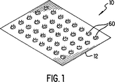
図1は、本発明の実施形態による微小侵入体列の透視図である。
図2は、図1の発明の実施形態による円錐状微小侵入体の透視図である。
図3は、皮膚に侵入する、図1の一連の微小侵入体の断面及び拡散のみによる薬剤の等濃度線を示す断面図である。
図4は、皮膚に侵入する、図1の一連の微小侵入体の断面及び吸引中の皮膚内の等圧線を示す断面図である。
図5は、皮膚に侵入する、図1の一連の微小侵入体の断面及び拡散及び吸引の双方による薬剤の等濃度線を示す断面図である。
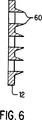
図6は、本発明の実施形態による一連の微小侵入体の断面図である。
図7は、本発明の代替実施形態による微小侵入体列の透視図である。
図8は、本発明の代替実施形態による図7の一連の微小侵入体の断面図である。
図9は、吸引及び液体薬剤の同時適用のための2つの充実空間を示した、本発明の実施形態の展開図である。
特殊実施形態の詳細な説明
局所適用リドカイン及びインシュリンのような多くの有用な治療薬剤は、真皮上層内への拡散によって体内へ導入され得る。生きた組織から成る真皮は、人体自身のリンパ液のような流体に対し高度な浸透性がある。しかし、外部の薬剤を体外から真皮内に導入するためには、流体に対して極端に低い浸透性を有する表皮の角質層を横切る必要がある。
吸引、拡散又は濃度、圧力勾配又はその他の任意の組合せのいずれによるかにかかわらず、液状又はガス状の治療薬剤又は他の物質が、組織を通して流入、流出又は移動する過程は、本明細書及び特許請求の範囲では「移送」と呼ぶ。さらに、本明細書及び特許請求の範囲で用いる「微小侵入体」は、実質的に真皮の敏感な皮内に侵入することなく表皮の枯皮に穴を開けるのに用いられ得る鋭い突起を指す。表皮に穴を開けることによって、多くの治療薬剤を真皮内へ導入するために微小侵入体を有効に用いることができる。特定化合物の侵入を可能にするのに要する表皮の裂け目の大きさは、化合物の特殊な分子構造に依存する。ある場合には、治療薬剤を通すのに要する大きさは顕微鏡的に微小で、ミクロン程度である。本明細書及び特許請求の範囲では「微小裂」の用語は、本発明によりそれを通して治療薬剤が真皮内に到達できる表皮の裂け目を指す。微小裂は、真皮の顕微鏡的裂け目として自然発生するか若しくは、上記のように、微小侵入体の穴開け作用を通して誘発され得る。
治療的に有効な量の治療薬剤を真皮内へ通すためには、各々が真皮に対する流体薬剤の小部分を伝える、複数の微小裂を用いることが必要になり得る。表皮を通して真皮内へ流体を導入するために1以上の微小侵入体を用いる方法及び装置並びに同一目的の装置を製造する手段につき、図1−9を参照して以下に述べる。同図では、同一参照番号は本発明の同一又は対応する要素を指す。
図1を参照すると、概して参照番号10で示される微小侵入体を並べたものが透視図で示される。微小侵入体列10は、薄い箔から成るシート12で構成される。望ましい実施形態では、シート12はステンレス鋼のような硬化金属で、厚さが約0.0005−0.003インチ(0.5−0.3ミル又は約13−75ミクロン)である。他の材料もシートの被覆及び処理材として用いられ得る。これらはすべて請求された本発明の範疇に属する。本明細書及び特許請求の範囲ではシート12は「プラテン」としても同様に言及される。プラテン12の面積は、概して1平方センチ程度である。しかし、以下に詳述するように、体内へ導入される流体量及び必要な拡散深さを達成するために流体が有効的に導入される速度に依存して大小の寸法が用いられる。プラテン12は、以下に述べるように、容易に製造されかつ表皮を通して伝染性又は毒性物質の導入を防止するために容易に殺菌される。
微小侵入体は、一連の切込み、スロット14(図7)又は突起によってプラテン12の連続性を中断させることによって作られる。本発明の実施形態を示す図2では、プラテン12を貫通して穿孔(パンチ)することにより微小侵入体60が作られてぎざぎざの端62が残され、それにより角質層を通した流体が導入される。さらに以下述べるように、他の形状の微小侵入体も本発明の範囲内にある。円錐又は噴火口状の形状が例示されているが、他の形状の切込み又はスロットを用いてもよい。望ましい実施形態では、概して10×10微小侵入体がプラテン12内にパンチされる。再び図1を参照すると、微小侵入体60間の間隔は0.10インチ(2.5mm)程度であるが、正確な絶対及び相対的寸法は、以下に述べる物質及び治療パラメータに依存する。望まし実施形態では、配列の間隔は図示の通り一定であるか若しくは必要とされる拡散深度輪郭に依存して任意でもよい。望まし実施形態では、表皮組織を切離すために鋭い、ぎざぎざのある、非常に強い微小侵入体60の端62が以下に述べる製造方法で作られる。プラテン12が患者の皮膚に対してしっかり押付けられると、微小侵入体60は、近似的に標準表皮層の厚さだけ又は1ミル(25ミクロン)程度真皮に向けて侵入する。
図3−5を参照して真皮内に流体を導入する機構につき以下に述べる。そこでは患者の皮膚が断面で示され、皮膚20が表皮22及び周囲環境間の境界面を構成する。境界面24は、真皮から表皮22を分離する。既に定めたように微小裂26は、微小侵入体の切離し動作によって生じる表皮の裂け目である。一定の流体薬剤導入に対しては、微小侵入体がプラテン面の外側に突出する必要はない。それは表皮がスロット端の厳密な曲率半径の回りで真空により吸引されているからである。微小裂26の正確な形状は円筒状又は不規則でよく、それは本論議では重大ではない。微小侵入体は完全なカニューレでよいが、これは多くの場合において不必要である。流体の表面張力及び表皮における毛管作用が微小裂26内への流体流入の案内となるからである。
慣用的に流体は体内の内部圧力より高い圧力を流体に与えることによって体内へ注入されるが、本発明の望ましい実施形態では2つの他の原理が採用される。その1つは拡散で、液体が高濃度から低濃度の場所へ流れる性質である。初等物理学で良く知られている通り、流れJは液体の濃度勾配ρに比例する、即ち、
J=−a2▽ρ
ここで、aは拡散定数であり、皮膚組織を通る流体の浸透、特に組織の多孔性と比例した注入される薬剤の分子寸法について説明する。比例の意味は、液体が高濃度から低濃度の領域へ流れることを反映する。微小裂30を介して系内へ導入される流体28が保存されるので下式が成り立つ。
∂ρ/∂t=−▽・J
同式は、各微小容量要素を囲む表面から流出する流れは、同要素内に含まれる流体の減分と等しいことを表す。拡散のみを考慮すると、上記2式の組合せは下記拡散式で与えられる真皮内の流体に対する空間的分布に帰着する。
∂ρ/∂t=a2▽2ρ
この性質は皮膚の「はじき出し」動作を反映する。3次元拡散式の解は、真皮内の正確な流体分布、特に微小裂の底面32から放射する流体28の等濃度線を与え、濃度は真皮内へ向けて殆ど指数的に減少する。従って、もし等値線34が組織の半飽和の等値線を表すなら、1/4飽和等値線36は微小裂の底面32からの等値線34よりさらに半飽和だけ真皮内にある。
しかし、効果的に皮下導入される薬剤の中には、拡散のみでは真皮内へ有効量の薬剤を導入させるのに不十分なものもある。真皮のような多孔性媒体内への流体の流れJも、同様に下式による圧力勾配によって支配される。
∂J/∂t+RJ=F−▽ρ
ここでRは、導入される特定の流体によって流れる真皮の有効抵抗(皮膚の構造的輪郭を考慮した張筋かもしれない)、Fは、もしあるとすれば、流体を皮膚内へ注入するために加えられる力、ρは真皮内で圧力を特性づける場(フィールド)である。圧力勾配▽ρは、微小裂26の小部分に真空又は部分真空を適用することにより真皮内に生成される。その代わりに、圧力勾配▽ρは、表皮22に外部からの真空又は部分真空を当てることにより生成され得る。それは表皮が真皮からの外向きの空気流に浸透性があるからである。微小裂40において真空又は部分真空を適用することによる効果は図4に示される。底面42は、当てられた部分真空の圧力P2になり、一方等圧線43、45、47は連続的に増加する圧力を示し、表皮の透過性のためにその外面で周囲圧力、即ち、概して周囲大気圧と実質的に平衡状態にある、真皮の内部圧力P0になる傾向がある。等圧線43、45、47は、両者間に圧力勾配が存在する任意の多孔性媒体の区域を示す。
時間の関数としての真皮内の流体分布を得るために、微小侵入体が適用されている皮膚領域の一部に真空が適用されかつ微小侵入体を通して流体が真皮に加えられる時、浸透式は圧力抑制下で解かれる。真空又は部分真空を適用することによる効果は図5に示される。真空は、微小裂40又は、その代わりに、表皮を通して適用され、微小裂40底面42において低圧表面を生成する。隣接微小裂44は、表皮22を通して流体28の通過を可能にする。真皮内に生じる圧力勾配のために等圧線48、50、52は、より深い侵入に加えて、真空が適用されない状態よりは一層一様な流体の真皮内への侵入を示す。多孔性媒体内への流体28の移送経路、即ち、等圧線48、50、52に対して直角で、微小裂44から流体28内へ向けられるものは経路54で示され、部分真空が適用される微小裂40に向けて導入される。高圧区域から低圧区域に向けて等圧線48、50、52を横切る経路54の筋書きは多数回繰り返され、経路は高圧の各微小裂44から発して低圧の各微小裂40に向けられ得る。
拡散定数は深さ当りの容積と時間との積である尺度を定め、それによって微小穴の大きさ及び間隔並びに液体及び真空充実空間間に適用される差動圧力が最適化され、処与の分子構造の治療薬剤に対する必要な深さの侵入が与えられるようにされる。
液体及び真皮間に処与の境界面領域を与えるために、中央間隔に対する微小裂直径の比が微小裂の合計数に対して兼ね合わされなければならない。これは、組織内の特定薬剤の拡散定数a及び有効抵抗Rを含むシステムの物質パラメータに対する上記式の解を必要とする。
図6は、図1及び2の微小侵入体の形状を輪郭で示す。微小侵入体の代わりの形状が図7について理解されよう。本発明のこの代替実施形態では、微小侵入体は一連の切込み又はスロット14によりプラテン12の連続性を中断させることによって生成される鋭端である。多くの他の形状の切込み又はスロットが用いられ得るが、山形又は半月形状のものが例示される。本実施例のスロットは直線寸法で0.050インチ(1.3mm)程度である。
表皮組織を切離すための本実施形態の微小侵入体は、舌状体16をプラテン12平面から外方に僅かに曲げることによって生成され、プラテン12が患者の皮膚にしっかり押し付けられると、微小侵入体が約標準表皮層の厚さ、即ち、1ミル(25ミクロン)だけ真皮に向けて侵入するようにされる。図8には、図7の舌状体がプラテン12平面の外へ押し出されたものが断面で示される。
低圧の小領域と注入された流体の小領域が交互に存在する構成を生成するためには各種の実施形態が用いられ得る。図9を参照すると、望ましい実施形態では粘着物質70によりプラテン12が患者の皮膚領域に固定される。2重マニホールド72が、スロット14の小部分と充実空間74との結合及び充実空間74と連通することなく充実空間76と相補的スロット14の小部分との間に空気を吸い込み得る貫通経路82を与える。真空が充実空間76のホース80を通して引き込まれ、それによって患者の皮膚上の相互接続スロット14を介して引き込まれる。真空又は部分真空を生成するために、当業界では機械ポンプ又は化学反応のような手段がよく知られている。真空が充実空間76を介して引き込まれる一方で、ホース78又は、より一般的に、任意の種類の貯蔵器から充実空間74、さらに相互接続されたスロット14を介して流体が真皮内に導入され得る。通常流体は周囲圧力のものであるが、皮膚内へのより早い注入が指示される場合には、ホース78及び充実空間74を介して流体に追加の圧力が加えられ得る。移送の量及び速度は、皮膚内の流体の容量又は濃度センサによるか若しくは、その代わりに、移送装置内の流速又は容量センサで監視される得る。さらなる実施形態においては、例えば、血糖レベルのようなある生物反応を監視することによって監視される得る。用途によってこれが望ましい場合には、任意の上記センサによって測定される量に応答して、真皮内への流体導入速度が閉ループ式制御器によって制御され得る。
さらなる代替実施形態では、貫通スロット14以外のすべての空気通路に対してプラテン12を密閉する、単一充実空間が用いられる。この実施形態では、プラテン12が患者の皮膚領域に隣接して配置され、粘着物質、真空吸引又は直接加圧によって固定される。真空は、真空ホース80を通して空気を引き出すことによって、従来のポンプ装置を用いてプラテン12のスロットを通して引き込まれる。真空によりプラテン12に対して皮膚表面が引上げられるのみならず、追加的に患者の真皮以内に圧力勾配が生成される。それは空気に対する真皮の透過性が有限であるために表皮を通して空気も同様に引き込まれるからである。さらに、スロット14の端15である微小浸入体は、皮膚がプラテン12に対して引も込まれていることによって表皮内に導入される。外部バルブ(図示せず)操作によって流体はホース80内に導入され、充実空間76を埋め戻し、スロット14及び微小浸入体16を通して真皮内へ引き込まれる。
本明細書で述べた方法は臨床用途につき記載されているが、それ以外の用途にも適用され得る。概して本発明は、媒体が一方側のみから接近可能な多孔性媒体内で流体を特定な形で分配させることに適用され得る。本発明の記載された実施形態は単なる例を意図するものであり、当業者にとって多くの改変、修正が行えることは明らかである。この様な改変、修正は添付した特許請求の範囲の範囲内に入るものであることが意図される。TECHNICAL FIELD The present invention relates to a system for delivering therapeutic substances into the body. In particular, it relates to a convenient method and apparatus for transferring fluid with minimal penetration into the dermis.
BACKGROUND OF THE INVENTION The transmission of therapeutic fluid medication through the skin requires entry into the stratum corneum and skin layers, which are the outer layers of the epidermis. The skin layer usually provides a largely impervious barrier against the inflow or outflow of microorganisms and most other substances into the body. The penetration into the epidermis is customarily done with a hollow needle or cannula. The needle is chamfered at the intrusion end to provide a sharp tip to locally tear the skin during both the surface and the continuous invasion process that proceeds through the epidermal layer into the dermis. Some known methods apply suction around an infusion cannula that inflates or dilates the underlying blood vessel in order to more effectively infuse the substance through the vein. Since the dermis contains living nerve cells, needle penetration is often uncomfortable for the patient.
Some known methods of introducing drugs or other therapeutic agents into the body use multiple needles. Known methods using multiple needles require expensive equipment due to difficulty in manufacturing.
Other methods are known in the art for introducing a therapeutic agent into the dermis so that the therapeutic agent can be taken up by the circulatory system and distributed clinically to the body. One such method relies on the slow diffusion of the drug through the epidermis with a simple topical application such as a salve. Alternatively, one or more fluid drug streams are forced through the epidermis without further mechanical separation of the outer tissue layer by using a jet injector. In these methods relying on fluid passing through the epidermis, the dispersion rate and thus the total amount of drug introduced can be highly ambiguous and variable. This uncertainty is unacceptable for many applications, because exceeding the desired concentration makes the therapeutic agent dangerous or expensive.
SUMMARY OF THE INVENTION In accordance with one embodiment of the present invention, a method is provided for transporting material across an outer boundary of a porous medium as defined below. The method creates a pressure gradient along at least one path, each extending from a first zone of the porous medium to a second zone of the porous medium closest to the first zone, and the second zone at the outer surface of the porous medium. The pressure is less than the ambient pressure, allowing the material to be transported across the outer boundary of the porous medium through at least one microcrack. The term “microcrack” is defined below.
In an alternative embodiment of the invention, the substance is a liquid or therapeutic agent that can flow in or out of the porous medium, and the porous medium may be human tissue. The step of creating a pressure gradient includes puncturing at least one microcrack in the outer boundary of the porous medium having at least one microintruder. Further, the pressure gradient between the porous media sections can be created by aspirating a portion of the outer surface of the porous media, aspirating a small portion of the microintruder, and aspirating a small portion of the microcrack. In another embodiment of the present invention, at least one microintruder is porous by aspirating a portion of the outer boundary of the porous medium substantially surrounding the contact between the microintruder and the outer boundary of the porous medium. It is sucked into contact with the outer surface of the medium.
According to a further aspect of the invention, an apparatus is provided for transporting material across an outer boundary of a porous medium. The apparatus has a platen that has at least one hole and at least one microintruder coupled with the platen to separate microcracks in the outer boundary of the porous medium. Creating a pressure gradient along at least one path, each extending from the first zone of the porous medium to the second zone of the porous medium closest to the first zone, so that the pressure of the second zone around the outer surface of the porous medium A vacuum device is provided so as to be less than the pressure of the vacuum. A reservoir is also provided for supplying the material to at least one microintruder that causes the material to be transferred into the porous medium. In an alternative embodiment of the device, a partial vacuum is provided that sucks the outer surface of the porous medium against at least one microintruder, while in a further alternative embodiment, each is transferred into a porous medium having an output. There is provided at least one sensor for monitoring the amount of material to be monitored and a controller for controlling the rate of material supplied by the reservoir based on the sensor output. In addition, at least one sensor is provided that monitors a biological response to the transfer of material across the outer boundary of the porous medium, and a controller that controls the rate at which the material is delivered based on the sensor output.
According to a further aspect of the invention, there is provided a method of manufacturing an apparatus for transferring material across an outer boundary of a porous medium. The method punches a series of protrusions on the surface of a thin flat platen to punch a hole in the platen, joins the first filling space with the first small portion of the platen hole, and then creates the second filling space. Coupling with the second small portion of the platen hole. In an alternative embodiment of the invention, the protrusion punched on the surface of the thin flat platen is conical.
In another embodiment of the manufacturing method of the present invention, an alternative method of an apparatus for transferring material across the outer boundary of a porous medium is provided. The method punches a series of peninsular tongues on the surface of a thin flat platen, pushes down the peninsular tongue below the platen surface so as to make a hole in the platen, and opens the first filling space to the platen hole. Coupling with the first small portion and then coupling the second filling space with the second small portion of the platen hole.
The fluid transfer system described herein provides the ability to effectively introduce a well-controlled and reproducible amount of liquid through the epidermis without local impact on the underlying dermis. An additional advantage of the present invention is to provide an inexpensive device for introducing liquid medication through the epidermis. Some of the other objects and advantages of the present invention are obvious and some are pointed out below. The invention will be more readily understood by reference to the following description in conjunction with the accompanying drawings.
[Brief description of the drawings]
FIG. 1 is a perspective view of a micro intruder array according to an embodiment of the present invention.
FIG. 2 is a perspective view of a conical microintruder according to the embodiment of the invention of FIG.
FIG. 3 is a cross-sectional view showing a cross-section of the series of micro-intruders of FIG.
FIG. 4 is a cross-sectional view showing the cross-section of the series of micro-invasive bodies of FIG.
FIG. 5 is a cross-sectional view of the series of micro-intruders of FIG. 1 that penetrates the skin and shows the isoline of the drug due to both diffusion and aspiration.
FIG. 6 is a cross-sectional view of a series of microintruders according to an embodiment of the present invention.
FIG. 7 is a perspective view of a microintruder array according to an alternative embodiment of the present invention.
FIG. 8 is a cross-sectional view of the series of microintruders of FIG. 7 according to an alternative embodiment of the present invention.
9, two solid space for suction and simultaneous application of the liquid agent was shown an exploded view of an embodiment of the present invention.
Detailed Description of Special Embodiments Topically applied Many useful therapeutic agents such as lidocaine and insulin can be introduced into the body by diffusion into the upper dermis. The dermis, which consists of living tissue, is highly permeable to fluids such as the body's own lymph. However, in order to introduce an external drug from outside the body into the dermis, it is necessary to cross the stratum corneum of the epidermis which has extremely low permeability to fluid.
The process by which a liquid or gaseous therapeutic agent or other substance flows in, out or moves through tissue, whether by aspiration, diffusion or concentration, pressure gradient or any other combination, is described herein and In the claims, this is called “transfer”. Further, as used herein and in the claims, “microintruder” refers to a sharp protrusion that can be used to puncture the epidermis without peeling into the sensitive skin of the dermis. . By puncturing the epidermis, micro-invasive bodies can be used effectively to introduce many therapeutic agents into the dermis. The size of the epidermal rift required to allow entry of a specific compound depends on the specific molecular structure of the compound. In some cases, the size required to pass the therapeutic agent is microscopically small, on the order of microns. As used herein and in the claims, the term “microfissure” refers to a tear in the epidermis through which the therapeutic agent can reach the dermis according to the present invention. Microcracks may occur spontaneously as microscopic tears in the dermis or can be induced through the piercing action of microinvaders as described above.
In order to pass a therapeutically effective amount of therapeutic agent into the dermis, it may be necessary to use multiple microcracks, each carrying a small portion of the fluid agent to the dermis. A method and apparatus that uses one or more microintruders to introduce fluid through the epidermis and into the dermis, as well as means for producing the same purpose apparatus, are described below with reference to FIGS. In the figure, the same reference numerals refer to the same or corresponding elements of the present invention.
Referring to FIG. 1, an array of micro-invasive bodies generally indicated by
The microintruder is made by interrupting the continuity of the
A mechanism for introducing fluid into the dermis will be described below with reference to FIGS. There, the patient's skin is shown in cross section, and the
Conventionally, fluid is injected into the body by applying a higher pressure to the fluid than the internal pressure in the body, but two other principles are employed in the preferred embodiment of the present invention. One of them is diffusion, which is the property that liquid flows from a high concentration to a low concentration. As is well known in elementary physics, the flow J is proportional to the concentration gradient ρ of the liquid, ie
J = -a 2 ▽ ρ
Here, a is a diffusion constant and describes the permeation of fluid through the skin tissue, particularly the molecular size of the injected drug proportional to the porosity of the tissue. The meaning of proportionality reflects that the liquid flows from a high concentration to a low concentration region. Since the fluid 28 introduced into the system through the
∂ρ / ∂t =-▽ ・ J
This equation represents that the flow out of the surface surrounding each microcapacitor element is equal to the decrement of the fluid contained within the element. When only diffusion is considered, the combination of the above two formulas results in a spatial distribution for the fluid in the dermis given by the following diffusion formula.
∂ρ / ∂t = a 2 ▽ 2 ρ
This property reflects the skin's “repel” behavior. The solution of the three-dimensional diffusion formula gives an accurate fluid distribution in the dermis, in particular an isoconcentration of the fluid 28 radiating from the
However, some drugs that are effectively introduced subcutaneously are not sufficient to introduce an effective amount of the drug into the dermis by diffusion alone. The fluid flow J into a porous medium such as the dermis is also governed by the pressure gradient according to the following equation.
∂J / ∂t + RJ = F- ▽ ρ
Where R is the effective resistance of the dermis that flows with the particular fluid being introduced (may be a tension that takes into account the structural contours of the skin), and F is for injecting fluid into the skin, if any The force, ρ, is the field that characterizes the pressure in the dermis. A pressure gradient ρρ is generated in the dermis by applying a vacuum or partial vacuum to a small portion of the
In order to obtain fluid distribution within the dermis as a function of time, osmotic pressure is applied when a vacuum is applied to a portion of the skin area to which the microinvasive body is applied and fluid is applied to the dermis through the microinvasive body. Solved under restraint. The effect of applying a vacuum or partial vacuum is shown in FIG. A vacuum is applied through the
The diffusion constant scales the product of volume per depth and time, thereby optimizing the size and spacing of the microholes and the differential pressure applied between the liquid and the vacuum-filled space. The required depth of penetration into the therapeutic agent of molecular structure is provided.
In order to provide a given interface area between the liquid and the dermis, the ratio of the microcrack diameter to the central spacing must be balanced against the total number of microcracks. This requires the solution of the above equation for the material parameters of the system including the diffusion constant a and the effective resistance R of the specific drug in the tissue.
FIG. 6 shows in outline the shape of the microintruder of FIGS. An alternative shape for the microintruder will be understood with respect to FIG. In this alternative embodiment of the invention, the microintruder is a sharp tip created by interrupting the continuity of the
The micro-invasive body of the present embodiment for severing epidermal tissue is generated by bending the
Various embodiments can be used to create a configuration in which there are alternating subregions of low pressure and subregions of injected fluid . Referring to FIG. 9, in a preferred embodiment, the
In a further alternative embodiment, a single solid space is used that seals the
Although the methods described herein have been described for clinical applications, they can be applied to other applications. In general, the present invention can be applied to distribute fluid in a specific manner within a porous medium accessible from only one side of the medium. The described embodiments of the invention are intended to be examples only, and it will be apparent to those skilled in the art that many changes and modifications can be made. Such alterations and modifications are intended to fall within the scope of the appended claims.
Claims (7)
物質を該多孔性媒体内へ導く装置であって、少なくとも1つの微小裂を介して該物質を該多孔性媒体内へ導くための装置と、An apparatus for directing a substance into the porous medium, the apparatus for guiding the substance into the porous medium via at least one microcrack;
該プラテンと結合される、該多孔性媒体の該外部境界の少なくとも1つの微小裂を切り裂く少なくとも1つの微小侵入体と、At least one microintruder that tears at least one microcrack of the outer boundary of the porous medium associated with the platen;
該多孔性媒体内に該物質を移送するようにさせるために、少なくとも1つの微小侵入体に物質を供給する貯蔵器と、A reservoir for supplying the substance to at least one microintruder to cause the substance to be transferred into the porous medium;
から成る多孔性媒体の外部境界を横切って物質を移送させる装置において、An apparatus for transporting material across the outer boundary of a porous medium comprising:
少なくとも1経路に沿って圧力勾配を生じさせる真空装置であって、各経路が微小裂から該多孔性媒体の第1区域まで及び該第1区域から該第1区域 に最も近い該多孔性媒体の第2区域まで達し、該第2区域での圧力が該多孔性媒体の外部境界外での周囲圧力未満になるようにさせる真空装置、A vacuum device that creates a pressure gradient along at least one path, each path of the porous medium from the microcrack to the first zone of the porous medium and from the first zone to the first zone closest to the first zone. A vacuum device that reaches the second zone and causes the pressure in the second zone to be less than the ambient pressure outside the outer boundary of the porous medium;
を備えていることを特徴とする物質移送装置。A mass transfer device comprising:
該多孔性媒体の該外部境界を横切って移送される物質の量を監視し、及び/又は、該多孔性媒体の該外部境界を横切って移送される物質に対する生物的応答を監視する出力を有する少なくとも1つのセンサと、Monitoring the amount of material transferred across the outer boundary of the porous medium and / or having an output to monitor biological response to the material transferred across the outer boundary of the porous medium At least one sensor;
各センサの該出力に基づいて該貯蔵器によって供給される該物質の速度を制御する制御器と、A controller for controlling the rate of the substance supplied by the reservoir based on the output of each sensor;
を更に備えていることを特徴とする物質移送装置。The mass transfer apparatus further comprising:
少なくとも1つの微小侵入体に対して該多孔性媒体の該外面を引き込む部分真空を作り出すための手段を更に備えていることを特徴とする物質移送装置。A mass transfer device further comprising means for creating a partial vacuum that draws the outer surface of the porous medium against at least one microintruder.
薄い平らなプラテンの表面に一連の突起を打抜き、Punch a series of protrusions on the surface of a thin flat platen,
充実空間を該プラテンの穴の全ての部分と結合させる、Combining the full space with all parts of the platen hole,
ことから成ることを特徴とする物質移送装置の製造方法。A method for manufacturing a mass transfer apparatus, comprising:
一連の突起を打抜く該段階が、中央穴を有する一連の突起を打抜くものであることを特徴とする物質移送装置の製造方法。A method for manufacturing a mass transfer apparatus, wherein the step of punching a series of protrusions is for punching a series of protrusions having a central hole.
該一連の突起を打抜く段階が、円錐状突起を含むことを特徴とする物質移送装置の製造方法。The method of manufacturing a mass transfer apparatus, wherein the step of punching the series of protrusions includes a conical protrusion.
第1充実空間を該プラテンの該穴の第1小部分と結合させ、Combining the first solid space with the first small portion of the hole in the platen;
第2充実空間を該プラテンの該穴の第2小部分と結合させることCoupling a second filling space with a second small portion of the hole in the platen
を特徴とする物質移送装置の製造方法。A method for manufacturing a mass transfer device.
Applications Claiming Priority (5)
| Application Number | Priority Date | Filing Date | Title |
|---|---|---|---|
| US2626696P | 1996-09-17 | 1996-09-17 | |
| US60/026,266 | 1996-09-17 | ||
| US3903697P | 1997-02-24 | 1997-02-24 | |
| US60/039,036 | 1997-02-24 | ||
| PCT/US1997/016454 WO1998011937A1 (en) | 1996-09-17 | 1997-09-15 | System for delivery of drugs by transport |
Related Child Applications (1)
| Application Number | Title | Priority Date | Filing Date |
|---|---|---|---|
| JP2007216091A Division JP2007325955A (en) | 1996-09-17 | 2007-08-22 | System for delivery of drug by transport |
Publications (3)
| Publication Number | Publication Date |
|---|---|
| JP2002510982A JP2002510982A (en) | 2002-04-09 |
| JP2002510982A5 JP2002510982A5 (en) | 2005-05-12 |
| JP4054381B2 true JP4054381B2 (en) | 2008-02-27 |
Family
ID=26700996
Family Applications (2)
| Application Number | Title | Priority Date | Filing Date |
|---|---|---|---|
| JP51483398A Expired - Lifetime JP4054381B2 (en) | 1996-09-17 | 1997-09-15 | Drug delivery system by transfer |
| JP2007216091A Pending JP2007325955A (en) | 1996-09-17 | 2007-08-22 | System for delivery of drug by transport |
Family Applications After (1)
| Application Number | Title | Priority Date | Filing Date |
|---|---|---|---|
| JP2007216091A Pending JP2007325955A (en) | 1996-09-17 | 2007-08-22 | System for delivery of drug by transport |
Country Status (7)
| Country | Link |
|---|---|
| US (1) | US5983136A (en) |
| EP (1) | EP0934093B1 (en) |
| JP (2) | JP4054381B2 (en) |
| AT (1) | ATE231015T1 (en) |
| CA (1) | CA2265906C (en) |
| DE (1) | DE69718495T2 (en) |
| WO (1) | WO1998011937A1 (en) |
Families Citing this family (135)
| Publication number | Priority date | Publication date | Assignee | Title |
|---|---|---|---|---|
| WO1996037256A1 (en) * | 1995-05-22 | 1996-11-28 | Silicon Microdevices, Inc. | Micromechanical patch for enhancing the delivery of compounds through the skin |
| US7214847B1 (en) | 1997-09-22 | 2007-05-08 | Argentum Medical, L.L.C. | Multilayer conductive appliance having wound healing and analgesic properties |
| US6861570B1 (en) * | 1997-09-22 | 2005-03-01 | A. Bart Flick | Multilayer conductive appliance having wound healing and analgesic properties |
| US8455710B2 (en) * | 1997-09-22 | 2013-06-04 | Argentum Medical, Llc | Conductive wound dressings and methods of use |
| US8801681B2 (en) * | 1995-09-05 | 2014-08-12 | Argentum Medical, Llc | Medical device |
| US5814094A (en) | 1996-03-28 | 1998-09-29 | Becker; Robert O. | Iontopheretic system for stimulation of tissue healing and regeneration |
| US6230051B1 (en) * | 1996-06-18 | 2001-05-08 | Alza Corporation | Device for enhancing transdermal agent delivery or sampling |
| EP2428249B1 (en) * | 1998-07-13 | 2015-10-07 | Inovio Pharmaceuticals, Inc. | Skin and muscle-targeted gene therapy by pulsed electrical field |
| US7922709B2 (en) | 1998-07-13 | 2011-04-12 | Genetronics, Inc. | Enhanced delivery of naked DNA to skin by non-invasive in vivo electroporation |
| US6678556B1 (en) * | 1998-07-13 | 2004-01-13 | Genetronics, Inc. | Electrical field therapy with reduced histopathological change in muscle |
| US6256533B1 (en) | 1999-06-09 | 2001-07-03 | The Procter & Gamble Company | Apparatus and method for using an intracutaneous microneedle array |
| AU6076200A (en) | 1999-07-08 | 2001-01-30 | Johnson & Johnson Consumer Companies, Inc. | Exothermic bandage |
| US6890553B1 (en) | 1999-07-08 | 2005-05-10 | Johnson & Johnson Consumer Companies, Inc. | Exothermic topical delivery device |
| US20030078499A1 (en) * | 1999-08-12 | 2003-04-24 | Eppstein Jonathan A. | Microporation of tissue for delivery of bioactive agents |
| US7113821B1 (en) | 1999-08-25 | 2006-09-26 | Johnson & Johnson Consumer Companies, Inc. | Tissue electroperforation for enhanced drug delivery |
| US7133717B2 (en) | 1999-08-25 | 2006-11-07 | Johnson & Johnson Consumer Companies, Inc. | Tissue electroperforation for enhanced drug delivery and diagnostic sampling |
| US6502574B2 (en) | 1999-09-17 | 2003-01-07 | Pi Medical, Inc. | Lateral stiffening snoring treatment |
| US6431174B1 (en) | 2000-08-10 | 2002-08-13 | Pi Medical, Inc. | Method and apparatus to treat conditions of the naso-pharyngeal area |
| US6231561B1 (en) * | 1999-09-20 | 2001-05-15 | Appriva Medical, Inc. | Method and apparatus for closing a body lumen |
| US8465468B1 (en) | 2000-06-29 | 2013-06-18 | Becton, Dickinson And Company | Intradermal delivery of substances |
| CN1390148A (en) * | 1999-11-15 | 2003-01-08 | 维尔克鲁工业公司 | Skin attachment member |
| EP1239916B1 (en) | 1999-12-10 | 2005-11-23 | ALZA Corporation | Device and method for enhancing microprotrusion skin piercing |
| US6497676B1 (en) | 2000-02-10 | 2002-12-24 | Baxter International | Method and apparatus for monitoring and controlling peritoneal dialysis therapy |
| US7404815B2 (en) | 2000-05-01 | 2008-07-29 | Lifescan, Inc. | Tissue ablation by shear force for sampling biological fluids and delivering active agents |
| US6659982B2 (en) * | 2000-05-08 | 2003-12-09 | Sterling Medivations, Inc. | Micro infusion drug delivery device |
| US6595947B1 (en) | 2000-05-22 | 2003-07-22 | Becton, Dickinson And Company | Topical delivery of vaccines |
| US6440096B1 (en) * | 2000-07-14 | 2002-08-27 | Becton, Dickinson And Co. | Microdevice and method of manufacturing a microdevice |
| NZ524646A (en) | 2000-09-08 | 2004-10-29 | Alza Corp | Methods for inhibiting decrease in transdermal drug flux by inhibition of pathway closure |
| CN1250171C (en) | 2000-10-13 | 2006-04-12 | 阿尔扎公司 | Apparatus and method for piercing skin with microtrusions |
| US7419481B2 (en) | 2000-10-13 | 2008-09-02 | Alza Corporation | Apparatus and method for piercing skin with microprotrusions |
| JP4198985B2 (en) | 2000-10-13 | 2008-12-17 | アルザ・コーポレーシヨン | Microblade array impact applicator. |
| MXPA03003303A (en) * | 2000-10-13 | 2004-12-13 | Johnson & Johnson | Microprotrusion member retainer for impact applicator. |
| US7131987B2 (en) | 2000-10-16 | 2006-11-07 | Corium International, Inc. | Microstructures and method for treating and conditioning skin which cause less irritation during exfoliation |
| US7108681B2 (en) | 2000-10-16 | 2006-09-19 | Corium International, Inc. | Microstructures for delivering a composition cutaneously to skin |
| US7828827B2 (en) | 2002-05-24 | 2010-11-09 | Corium International, Inc. | Method of exfoliation of skin using closely-packed microstructures |
| ATE428466T1 (en) | 2000-10-26 | 2009-05-15 | Alza Corp | TRANSDERMAL DRUG DELIVERY SYSTEM WITH COATED MICROPROOFS |
| MXPA03006852A (en) | 2001-01-31 | 2004-05-31 | Velcro Ind | Direct hook engagement. |
| US6663820B2 (en) | 2001-03-14 | 2003-12-16 | The Procter & Gamble Company | Method of manufacturing microneedle structures using soft lithography and photolithography |
| WO2002074173A1 (en) | 2001-03-16 | 2002-09-26 | Alza Corporation | Method and apparatus for coating skin piercing microprojections |
| EP1752189A3 (en) | 2001-04-20 | 2007-02-21 | Alza Corporation | Microprojection array having a beneficial agent containing coating |
| MXPA03009603A (en) * | 2001-04-20 | 2004-12-06 | Johnson & Johnson | Microprojection array having a beneficial agent containing coating. |
| US20020193729A1 (en) * | 2001-04-20 | 2002-12-19 | Cormier Michel J.N. | Microprojection array immunization patch and method |
| US6790179B2 (en) | 2001-08-01 | 2004-09-14 | Johnson & Johnson Consumer Companies, Inc. | Method of examining and diagnosing skin health |
| US6840910B2 (en) | 2001-08-01 | 2005-01-11 | Johnson & Johnson Consumer Companies, Inc. | Method of distributing skin care products |
| US6855117B2 (en) | 2001-08-01 | 2005-02-15 | Johnson & Johnson Consumer Companies, Inc. | Method of treating the skin of a subject |
| US7429258B2 (en) * | 2001-10-26 | 2008-09-30 | Massachusetts Institute Of Technology | Microneedle transport device |
| US20040120964A1 (en) * | 2001-10-29 | 2004-06-24 | Mikszta John A. | Needleless vaccination using chimeric yellow fever vaccine-vectored vaccines against heterologous flaviviruses |
| JP2005511248A (en) * | 2001-10-29 | 2005-04-28 | ベクトン・ディキンソン・アンド・カンパニー | Methods and devices for delivering substances |
| US20030125662A1 (en) | 2002-01-03 | 2003-07-03 | Tuan Bui | Method and apparatus for providing medical treatment therapy based on calculated demand |
| US7146981B2 (en) * | 2002-02-04 | 2006-12-12 | Restore Medical, Inc. | Pharyngeal wall treatment |
| US7017582B2 (en) * | 2002-02-04 | 2006-03-28 | Restore Medical Inc. | Stiffening pharyngeal wall treatment |
| US9918665B2 (en) | 2002-03-11 | 2018-03-20 | Nitto Denko Corporation | Transdermal porator and patch system and method for using same |
| AU2003265226A1 (en) | 2002-03-11 | 2003-12-19 | Altea Therapeutics Corporation | Transdermal drug delivery device, method and use |
| US8116860B2 (en) | 2002-03-11 | 2012-02-14 | Altea Therapeutics Corporation | Transdermal porator and patch system and method for using same |
| US6945952B2 (en) | 2002-06-25 | 2005-09-20 | Theraject, Inc. | Solid solution perforator for drug delivery and other applications |
| KR20120087197A (en) | 2002-07-19 | 2012-08-06 | 쓰리엠 이노베이티브 프로퍼티즈 컴파니 | Microneedle device, method of using microneedle device and method of delivering microneedle device |
| US7238164B2 (en) | 2002-07-19 | 2007-07-03 | Baxter International Inc. | Systems, methods and apparatuses for pumping cassette-based therapies |
| US20040194266A1 (en) * | 2002-08-19 | 2004-10-07 | Carter Linda A. | Burn, sunburn, and cellulite treatment system |
| CA2497154C (en) * | 2002-08-29 | 2012-01-03 | Becton, Dickinson And Company | Substance delivery via a rotating microabrading surface |
| US8062573B2 (en) * | 2002-09-16 | 2011-11-22 | Theraject, Inc. | Solid micro-perforators and methods of use |
| US20040236269A1 (en) | 2002-09-25 | 2004-11-25 | Marchitto Kevin S. | Microsurgical tissue treatment system |
| US7390330B2 (en) | 2002-09-27 | 2008-06-24 | Surgitech, Llc | Reciprocating surgical file |
| US7666186B2 (en) * | 2002-09-27 | 2010-02-23 | Surgitech, Llc | Surgical system with a blade |
| US20060264926A1 (en) * | 2002-11-08 | 2006-11-23 | Kochamba Gary S | Cutaneous stabilization by vacuum for delivery of micro-needle array |
| US6896666B2 (en) * | 2002-11-08 | 2005-05-24 | Kochamba Family Trust | Cutaneous injection delivery under suction |
| US7381222B2 (en) * | 2002-12-30 | 2008-06-03 | Quiescence Medical, Inc. | Stent for maintaining patency of a body region |
| US7992566B2 (en) | 2002-12-30 | 2011-08-09 | Quiescence Medical, Inc. | Apparatus and methods for treating sleep apnea |
| US7647931B2 (en) | 2002-12-30 | 2010-01-19 | Quiescence Medical, Inc. | Stent for maintaining patency of a body region |
| US7578954B2 (en) | 2003-02-24 | 2009-08-25 | Corium International, Inc. | Method for manufacturing microstructures having multiple microelements with through-holes |
| US20050123507A1 (en) * | 2003-06-30 | 2005-06-09 | Mahmoud Ameri | Formulations for coated microprojections having controlled solubility |
| CA2530531A1 (en) | 2003-06-30 | 2005-01-20 | Alza Corporation | Formulations for coated microprojections containing non-volatile counterions |
| AR044985A1 (en) * | 2003-07-02 | 2005-10-12 | Alza Corp | IMMUNIZATION METHOD AND PATCH BY MICROPROJECTION PROVISION |
| US8961477B2 (en) | 2003-08-25 | 2015-02-24 | 3M Innovative Properties Company | Delivery of immune response modifier compounds |
| CA2536443A1 (en) * | 2003-08-26 | 2005-03-03 | Alza Corporation | Device and method for intradermal cell implantation |
| US8016811B2 (en) * | 2003-10-24 | 2011-09-13 | Altea Therapeutics Corporation | Method for transdermal delivery of permeant substances |
| JP2007510445A (en) | 2003-10-24 | 2007-04-26 | アルザ・コーポレーシヨン | Pretreatment methods and systems for promoting transdermal drug delivery |
| BRPI0415986A (en) | 2003-10-28 | 2007-01-23 | Alza Corp | method and apparatus for reducing the incidence of tobacco use |
| JP4682144B2 (en) | 2003-10-31 | 2011-05-11 | アルザ・コーポレーシヨン | Self-actuating applicator for microprojection arrays |
| EP1706171A1 (en) * | 2003-12-29 | 2006-10-04 | 3M Innovative Properties Company | Medical devices and kits including same |
| JP2007523771A (en) * | 2004-02-23 | 2007-08-23 | スリーエム イノベイティブ プロパティズ カンパニー | Microneedle array molding method |
| WO2005094526A2 (en) | 2004-03-24 | 2005-10-13 | Corium International, Inc. | Transdermal delivery device |
| AU2005244734A1 (en) | 2004-05-13 | 2005-12-01 | Alza Corporation | Apparatus and method for transdermal delivery of parathyroid hormone agents |
| WO2005123173A1 (en) * | 2004-06-10 | 2005-12-29 | 3M Innovative Properties Company | Patch application device and kit |
| US7316665B2 (en) * | 2004-08-25 | 2008-01-08 | Becton, Dickinson And Company | Method and device for the delivery of a substance including a covering |
| KR20070099540A (en) * | 2004-09-08 | 2007-10-09 | 알자 코포레이션 | Microprojection array with improved skin adhesion and compliance |
| JP5015787B2 (en) | 2004-11-18 | 2012-08-29 | スリーエム イノベイティブ プロパティズ カンパニー | Contact coating method of microneedle array |
| BRPI0517749A (en) | 2004-11-18 | 2008-10-21 | 3M Innovative Properties Co | application device for applying a micro-needle device to a skin surface, and method for using an application device |
| KR101224257B1 (en) * | 2004-11-18 | 2013-01-18 | 쓰리엠 이노베이티브 프로퍼티즈 컴파니 | Masking method for coating a microneedle array |
| US9174035B2 (en) | 2004-11-18 | 2015-11-03 | 3M Innovative Properties Company | Microneedle array applicator and retainer |
| US8057842B2 (en) | 2004-11-18 | 2011-11-15 | 3M Innovative Properties Company | Method of contact coating a microneedle array |
| US20080307849A1 (en) * | 2004-11-26 | 2008-12-18 | Agency For Science, Technology And Research | Method And Apparatus For Forming Microstructures |
| AU2005314151B2 (en) | 2004-12-07 | 2011-09-08 | 3M Innovative Properties Company | Method of molding a microneedle |
| WO2006108185A1 (en) | 2005-04-07 | 2006-10-12 | 3M Innovative Properties Company | System and method for tool feedback sensing |
| US20070270738A1 (en) * | 2005-04-25 | 2007-11-22 | Wu Jeffrey M | Method of treating ACNE with stratum corneum piercing patch |
| US20060253078A1 (en) * | 2005-04-25 | 2006-11-09 | Wu Jeffrey M | Method of treating skin disorders with stratum corneum piercing device |
| US20080009802A1 (en) * | 2005-04-25 | 2008-01-10 | Danilo Lambino | Method of treating acne with stratum corneum piercing device |
| EP1904158B1 (en) | 2005-06-24 | 2013-07-24 | 3M Innovative Properties Company | Collapsible patch with microneedle array |
| ATE477833T1 (en) * | 2005-06-27 | 2010-09-15 | 3M Innovative Properties Co | MICRONEEDLE CARTRIDGE ASSEMBLY |
| JP5144510B2 (en) | 2005-06-27 | 2013-02-13 | スリーエム イノベイティブ プロパティズ カンパニー | Microneedle array application device |
| CN101687094B (en) * | 2005-09-06 | 2012-09-26 | 谢拉杰克特股份有限公司 | Solid solution perforator containing drug particle and/or drug-adsorbed particles |
| WO2007061964A1 (en) * | 2005-11-18 | 2007-05-31 | 3M Innovative Properties Company | Methods for coating microneedles |
| US20080262416A1 (en) * | 2005-11-18 | 2008-10-23 | Duan Daniel C | Microneedle Arrays and Methods of Preparing Same |
| US20070142885A1 (en) * | 2005-11-29 | 2007-06-21 | Reliant Technologies, Inc. | Method and Apparatus for Micro-Needle Array Electrode Treatment of Tissue |
| WO2007075614A1 (en) * | 2005-12-21 | 2007-07-05 | 3M Innovative Properties Company | Microneedle devices |
| WO2007124411A1 (en) | 2006-04-20 | 2007-11-01 | 3M Innovative Properties Company | Device for applying a microneedle array |
| WO2008006090A2 (en) | 2006-07-06 | 2008-01-10 | Quiescence Medical, Inc. | Apparatus and methods for treating sleep apnea |
| WO2008091602A2 (en) | 2007-01-22 | 2008-07-31 | Corium International, Inc. | Applicators for microneedle arrays |
| US8558964B2 (en) | 2007-02-15 | 2013-10-15 | Baxter International Inc. | Dialysis system having display with electromagnetic compliance (“EMC”) seal |
| US7998115B2 (en) | 2007-02-15 | 2011-08-16 | Baxter International Inc. | Dialysis system having optical flowrate detection |
| US8361023B2 (en) | 2007-02-15 | 2013-01-29 | Baxter International Inc. | Dialysis system with efficient battery back-up |
| US7731689B2 (en) | 2007-02-15 | 2010-06-08 | Baxter International Inc. | Dialysis system having inductive heating |
| US8870812B2 (en) | 2007-02-15 | 2014-10-28 | Baxter International Inc. | Dialysis system having video display with ambient light adjustment |
| WO2008130587A2 (en) | 2007-04-16 | 2008-10-30 | Corium International, Inc. | Solvent-cast microneedle arrays containing active |
| US8911749B2 (en) | 2007-04-16 | 2014-12-16 | Corium International, Inc. | Vaccine delivery via microneedle arrays |
| EP2244746B2 (en) † | 2008-02-27 | 2019-01-02 | Aplion Medical Corporation | Wound dressing with uniform distribution |
| CN102105108B (en) * | 2008-05-21 | 2013-12-04 | 谢拉杰克特股份有限公司 | Method of manufacturing solid solution peforator patches and uses thereof |
| AU2011248108B2 (en) | 2010-05-04 | 2016-05-26 | Corium Pharma Solutions, Inc. | Method and device for transdermal delivery of parathyroid hormone using a microprojection array |
| WO2012078649A1 (en) | 2010-12-06 | 2012-06-14 | Follica, Inc. | Methods for treating baldness and promoting hair growth |
| US9265649B2 (en) | 2010-12-13 | 2016-02-23 | Quiescence Medical, Inc. | Apparatus and methods for treating sleep apnea |
| CN105073178B (en) | 2012-12-21 | 2019-07-30 | 考里安国际公司 | Microarray and its application method for therapeutic agent delivering |
| WO2014126101A1 (en) | 2013-02-13 | 2014-08-21 | 久光製薬株式会社 | Microneedle array |
| WO2014164314A1 (en) | 2013-03-12 | 2014-10-09 | Corium International, Inc. | Microprojection applicators |
| EP2968118B1 (en) | 2013-03-15 | 2022-02-09 | Corium, Inc. | Microarray for delivery of therapeutic agent and methods of use |
| WO2014150285A2 (en) | 2013-03-15 | 2014-09-25 | Corium International, Inc. | Multiple impact microprojection applicators and methods of use |
| JP2016512754A (en) | 2013-03-15 | 2016-05-09 | コリウム インターナショナル, インコーポレイテッド | Microarray, method of use and manufacturing for delivery of therapeutic agents |
| EP2968116A1 (en) | 2013-03-15 | 2016-01-20 | Corium International, Inc. | Microarray with polymer-free microstructures, methods of making, and methods of use |
| US20150038897A1 (en) | 2013-07-30 | 2015-02-05 | Zosano Pharma, Inc. | Low-Profile Microneedle Patch Applicator |
| EP2905047A1 (en) * | 2014-02-10 | 2015-08-12 | LTS LOHMANN Therapie-Systeme AG | Micro-needle system and method for producing the same |
| US10624843B2 (en) | 2014-09-04 | 2020-04-21 | Corium, Inc. | Microstructure array, methods of making, and methods of use |
| WO2017004067A1 (en) | 2015-06-29 | 2017-01-05 | Corium International, Inc. | Microarray for delivery of therapeutic agent, methods of use, and methods of making |
| EP3380061A4 (en) | 2015-11-24 | 2019-07-24 | Insulet Corporation | Wearable automated medication delivery system |
| US11179516B2 (en) | 2017-06-22 | 2021-11-23 | Baxter International Inc. | Systems and methods for incorporating patient pressure into medical fluid delivery |
| KR102291392B1 (en) * | 2018-03-30 | 2021-08-20 | 랩앤피플주식회사 | Multi type micro-needle |
| US20230277759A1 (en) | 2022-03-03 | 2023-09-07 | Deka Products Limited Partnership | Systems, Methods, and Apparatuses for Medical Agent Administration |
| US20240024566A1 (en) | 2022-07-21 | 2024-01-25 | Deka Products Limited Partnership | Delivery Device Systems, Methods, and Apparatuses |
Family Cites Families (28)
| Publication number | Priority date | Publication date | Assignee | Title |
|---|---|---|---|---|
| US3617613A (en) * | 1968-10-17 | 1971-11-02 | Spaulding Fibre Co | Punchable printed circuit board base |
| US3675766A (en) * | 1970-02-04 | 1972-07-11 | Sol Roy Rosenthal | Multiple puncture injector device |
| US3964482A (en) * | 1971-05-17 | 1976-06-22 | Alza Corporation | Drug delivery device |
| BE795384A (en) * | 1972-02-14 | 1973-08-13 | Ici Ltd | DRESSINGS |
| BR7908937A (en) * | 1978-12-06 | 1981-06-30 | Svedman Paul | DEVICE FOR TREATING FABRICS, FOR EXAMPLE, SKIN |
| US4403609A (en) * | 1981-02-24 | 1983-09-13 | Cohen Edgar C | Vacuum-compression injector |
| US4421508A (en) * | 1981-02-24 | 1983-12-20 | Cohen Edgar C | Vacuum-compression injector |
| US4340048A (en) * | 1981-03-28 | 1982-07-20 | Alza Corporation | Self-driven hypodermic injector |
| US4447225A (en) * | 1982-03-22 | 1984-05-08 | Taff Barry E | Multidose jet injector |
| EP0209644A1 (en) * | 1985-05-02 | 1987-01-28 | Ivac Corporation | Electrochemically driven drug dispenser |
| US4711247A (en) * | 1986-04-18 | 1987-12-08 | Henry Fishman | Allergy testing method and apparatus |
| US5080648A (en) * | 1987-06-08 | 1992-01-14 | Antonio Nicholas F D | Hypodermic fluid dispenser |
| DE3735137A1 (en) * | 1987-10-16 | 1989-05-03 | Siemens Ag | ARRANGEMENT FOR DISPENSING MEDICINES IN AN IMPLANTABLE MEDICAL DEVICE |
| EP0347190A1 (en) * | 1988-06-14 | 1989-12-20 | Vci Corporation | Needleless vacuum-compression injector |
| GB2221394B (en) * | 1988-08-05 | 1992-03-04 | Eilert Eilertsen | An injection device |
| JPH02144077A (en) * | 1988-11-25 | 1990-06-01 | Olympus Optical Co Ltd | Drug administration apparatus |
| EP0429842B1 (en) * | 1989-10-27 | 1996-08-28 | Korea Research Institute Of Chemical Technology | Device for the transdermal administration of protein or peptide drug |
| US5279544A (en) * | 1990-12-13 | 1994-01-18 | Sil Medics Ltd. | Transdermal or interdermal drug delivery devices |
| SE9101022D0 (en) * | 1991-01-09 | 1991-04-08 | Paal Svedman | MEDICAL SUSPENSION DEVICE |
| US5312456A (en) * | 1991-01-31 | 1994-05-17 | Carnegie Mellon University | Micromechanical barb and method for making the same |
| US5153986A (en) * | 1991-07-17 | 1992-10-13 | International Business Machines | Method for fabricating metal core layers for a multi-layer circuit board |
| US5484399A (en) * | 1992-02-27 | 1996-01-16 | Sloan-Kettering Institute For Cancer Research | Process and device to reduce interstitial fluid pressure in tissue |
| US5309909A (en) * | 1992-05-22 | 1994-05-10 | Physio-Control Corporation | Combined skin preparation and monitoring electrode |
| US5702359A (en) * | 1995-06-06 | 1997-12-30 | Genetronics, Inc. | Needle electrodes for mediated delivery of drugs and genes |
| IE68890B1 (en) * | 1993-04-08 | 1996-07-24 | Elan Med Tech | Intradermal delivery device |
| DE59505328D1 (en) * | 1994-12-09 | 1999-04-15 | Novartis Ag | TRANSDERMAL SYSTEM |
| EP0858285A4 (en) * | 1995-08-29 | 2000-05-17 | Spectrx Inc | Microporation of human skin for drug delivery and monitoring applications |
| DE69722414T2 (en) * | 1996-07-03 | 2004-05-19 | Altea Therapeutics Corp. | MULTIPLE MECHANICAL MICROPERFORATION OF SKIN OR MUCOSA |
-
1997
- 1997-09-15 US US08/929,984 patent/US5983136A/en not_active Expired - Lifetime
- 1997-09-15 DE DE69718495T patent/DE69718495T2/en not_active Expired - Lifetime
- 1997-09-15 JP JP51483398A patent/JP4054381B2/en not_active Expired - Lifetime
- 1997-09-15 CA CA002265906A patent/CA2265906C/en not_active Expired - Lifetime
- 1997-09-15 WO PCT/US1997/016454 patent/WO1998011937A1/en active IP Right Grant
- 1997-09-15 EP EP97943340A patent/EP0934093B1/en not_active Expired - Lifetime
- 1997-09-15 AT AT97943340T patent/ATE231015T1/en not_active IP Right Cessation
-
2007
- 2007-08-22 JP JP2007216091A patent/JP2007325955A/en active Pending
Also Published As
| Publication number | Publication date |
|---|---|
| DE69718495D1 (en) | 2003-02-20 |
| CA2265906C (en) | 2003-11-11 |
| US5983136A (en) | 1999-11-09 |
| JP2007325955A (en) | 2007-12-20 |
| JP2002510982A (en) | 2002-04-09 |
| CA2265906A1 (en) | 1998-03-26 |
| DE69718495T2 (en) | 2003-11-20 |
| WO1998011937A1 (en) | 1998-03-26 |
| ATE231015T1 (en) | 2003-02-15 |
| EP0934093B1 (en) | 2003-01-15 |
| EP0934093A1 (en) | 1999-08-11 |
Similar Documents
| Publication | Publication Date | Title |
|---|---|---|
| JP4054381B2 (en) | Drug delivery system by transfer | |
| US10524730B2 (en) | Medical devices with microneedle arrays and methods for operating such medical devices | |
| US10525244B2 (en) | Microneedle arrays and methods for fabricating microneedle arrays | |
| US6607513B1 (en) | Device for withdrawing or administering a substance and method of manufacturing a device | |
| US6183434B1 (en) | Multiple mechanical microporation of skin or mucosa | |
| AU2002330234B2 (en) | Microdevice and method of delivering or withdrawing a substance through the skin of an animal | |
| US6440096B1 (en) | Microdevice and method of manufacturing a microdevice | |
| EP1735044B1 (en) | Multi-site injection system | |
| US9717451B2 (en) | Device for withdrawing or administering a substance and method of manufacturing a device | |
| US20090054842A1 (en) | Enhanced penetration system and method for sliding microneedles | |
| AU2002330234A1 (en) | Microdevice and method of delivering or withdrawing a substance through the skin of an animal |
Legal Events
| Date | Code | Title | Description |
|---|---|---|---|
| A521 | Request for written amendment filed |
Free format text: JAPANESE INTERMEDIATE CODE: A523 Effective date: 20040903 |
|
| A621 | Written request for application examination |
Free format text: JAPANESE INTERMEDIATE CODE: A621 Effective date: 20040903 |
|
| A977 | Report on retrieval |
Free format text: JAPANESE INTERMEDIATE CODE: A971007 Effective date: 20061013 |
|
| A131 | Notification of reasons for refusal |
Free format text: JAPANESE INTERMEDIATE CODE: A131 Effective date: 20061031 |
|
| A521 | Request for written amendment filed |
Free format text: JAPANESE INTERMEDIATE CODE: A523 Effective date: 20070125 |
|
| A02 | Decision of refusal |
Free format text: JAPANESE INTERMEDIATE CODE: A02 Effective date: 20070424 |
|
| A521 | Request for written amendment filed |
Free format text: JAPANESE INTERMEDIATE CODE: A523 Effective date: 20070822 |
|
| A521 | Request for written amendment filed |
Free format text: JAPANESE INTERMEDIATE CODE: A821 Effective date: 20070921 |
|
| A911 | Transfer to examiner for re-examination before appeal (zenchi) |
Free format text: JAPANESE INTERMEDIATE CODE: A911 Effective date: 20071101 |
|
| TRDD | Decision of grant or rejection written | ||
| A01 | Written decision to grant a patent or to grant a registration (utility model) |
Free format text: JAPANESE INTERMEDIATE CODE: A01 Effective date: 20071113 |
|
| A61 | First payment of annual fees (during grant procedure) |
Free format text: JAPANESE INTERMEDIATE CODE: A61 Effective date: 20071210 |
|
| FPAY | Renewal fee payment (event date is renewal date of database) |
Free format text: PAYMENT UNTIL: 20101214 Year of fee payment: 3 |
|
| R150 | Certificate of patent or registration of utility model |
Free format text: JAPANESE INTERMEDIATE CODE: R150 |
|
| FPAY | Renewal fee payment (event date is renewal date of database) |
Free format text: PAYMENT UNTIL: 20101214 Year of fee payment: 3 |
|
| FPAY | Renewal fee payment (event date is renewal date of database) |
Free format text: PAYMENT UNTIL: 20111214 Year of fee payment: 4 |
|
| FPAY | Renewal fee payment (event date is renewal date of database) |
Free format text: PAYMENT UNTIL: 20111214 Year of fee payment: 4 |
|
| FPAY | Renewal fee payment (event date is renewal date of database) |
Free format text: PAYMENT UNTIL: 20121214 Year of fee payment: 5 |
|
| FPAY | Renewal fee payment (event date is renewal date of database) |
Free format text: PAYMENT UNTIL: 20131214 Year of fee payment: 6 |
|
| R250 | Receipt of annual fees |
Free format text: JAPANESE INTERMEDIATE CODE: R250 |
|
| R250 | Receipt of annual fees |
Free format text: JAPANESE INTERMEDIATE CODE: R250 |
|
| R250 | Receipt of annual fees |
Free format text: JAPANESE INTERMEDIATE CODE: R250 |
|
| R250 | Receipt of annual fees |
Free format text: JAPANESE INTERMEDIATE CODE: R250 |
|
| EXPY | Cancellation because of completion of term |