JP2007523771A - Microneedle array molding method - Google Patents
Microneedle array molding method Download PDFInfo
- Publication number
- JP2007523771A JP2007523771A JP2006554275A JP2006554275A JP2007523771A JP 2007523771 A JP2007523771 A JP 2007523771A JP 2006554275 A JP2006554275 A JP 2006554275A JP 2006554275 A JP2006554275 A JP 2006554275A JP 2007523771 A JP2007523771 A JP 2007523771A
- Authority
- JP
- Japan
- Prior art keywords
- negative
- microneedle
- plastic material
- insert
- cavity
- Prior art date
- Legal status (The legal status is an assumption and is not a legal conclusion. Google has not performed a legal analysis and makes no representation as to the accuracy of the status listed.)
- Withdrawn
Links
Images


Classifications
-
- B—PERFORMING OPERATIONS; TRANSPORTING
- B29—WORKING OF PLASTICS; WORKING OF SUBSTANCES IN A PLASTIC STATE IN GENERAL
- B29C—SHAPING OR JOINING OF PLASTICS; SHAPING OF MATERIAL IN A PLASTIC STATE, NOT OTHERWISE PROVIDED FOR; AFTER-TREATMENT OF THE SHAPED PRODUCTS, e.g. REPAIRING
- B29C45/00—Injection moulding, i.e. forcing the required volume of moulding material through a nozzle into a closed mould; Apparatus therefor
- B29C45/17—Component parts, details or accessories; Auxiliary operations
- B29C45/26—Moulds
- B29C45/37—Mould cavity walls, i.e. the inner surface forming the mould cavity, e.g. linings
- B29C45/372—Mould cavity walls, i.e. the inner surface forming the mould cavity, e.g. linings provided with means for marking or patterning, e.g. numbering articles
-
- A—HUMAN NECESSITIES
- A61—MEDICAL OR VETERINARY SCIENCE; HYGIENE
- A61B—DIAGNOSIS; SURGERY; IDENTIFICATION
- A61B17/00—Surgical instruments, devices or methods, e.g. tourniquets
- A61B17/20—Surgical instruments, devices or methods, e.g. tourniquets for vaccinating or cleaning the skin previous to the vaccination
- A61B17/205—Vaccinating by means of needles or other puncturing devices
-
- A—HUMAN NECESSITIES
- A61—MEDICAL OR VETERINARY SCIENCE; HYGIENE
- A61M—DEVICES FOR INTRODUCING MEDIA INTO, OR ONTO, THE BODY; DEVICES FOR TRANSDUCING BODY MEDIA OR FOR TAKING MEDIA FROM THE BODY; DEVICES FOR PRODUCING OR ENDING SLEEP OR STUPOR
- A61M37/00—Other apparatus for introducing media into the body; Percutany, i.e. introducing medicines into the body by diffusion through the skin
- A61M37/0015—Other apparatus for introducing media into the body; Percutany, i.e. introducing medicines into the body by diffusion through the skin by using microneedles
-
- B—PERFORMING OPERATIONS; TRANSPORTING
- B29—WORKING OF PLASTICS; WORKING OF SUBSTANCES IN A PLASTIC STATE IN GENERAL
- B29C—SHAPING OR JOINING OF PLASTICS; SHAPING OF MATERIAL IN A PLASTIC STATE, NOT OTHERWISE PROVIDED FOR; AFTER-TREATMENT OF THE SHAPED PRODUCTS, e.g. REPAIRING
- B29C33/00—Moulds or cores; Details thereof or accessories therefor
- B29C33/38—Moulds or cores; Details thereof or accessories therefor characterised by the material or the manufacturing process
- B29C33/3842—Manufacturing moulds, e.g. shaping the mould surface by machining
-
- B—PERFORMING OPERATIONS; TRANSPORTING
- B29—WORKING OF PLASTICS; WORKING OF SUBSTANCES IN A PLASTIC STATE IN GENERAL
- B29C—SHAPING OR JOINING OF PLASTICS; SHAPING OF MATERIAL IN A PLASTIC STATE, NOT OTHERWISE PROVIDED FOR; AFTER-TREATMENT OF THE SHAPED PRODUCTS, e.g. REPAIRING
- B29C33/00—Moulds or cores; Details thereof or accessories therefor
- B29C33/42—Moulds or cores; Details thereof or accessories therefor characterised by the shape of the moulding surface, e.g. ribs or grooves
-
- B—PERFORMING OPERATIONS; TRANSPORTING
- B29—WORKING OF PLASTICS; WORKING OF SUBSTANCES IN A PLASTIC STATE IN GENERAL
- B29C—SHAPING OR JOINING OF PLASTICS; SHAPING OF MATERIAL IN A PLASTIC STATE, NOT OTHERWISE PROVIDED FOR; AFTER-TREATMENT OF THE SHAPED PRODUCTS, e.g. REPAIRING
- B29C45/00—Injection moulding, i.e. forcing the required volume of moulding material through a nozzle into a closed mould; Apparatus therefor
- B29C45/17—Component parts, details or accessories; Auxiliary operations
- B29C45/26—Moulds
- B29C45/37—Mould cavity walls, i.e. the inner surface forming the mould cavity, e.g. linings
-
- B—PERFORMING OPERATIONS; TRANSPORTING
- B29—WORKING OF PLASTICS; WORKING OF SUBSTANCES IN A PLASTIC STATE IN GENERAL
- B29C—SHAPING OR JOINING OF PLASTICS; SHAPING OF MATERIAL IN A PLASTIC STATE, NOT OTHERWISE PROVIDED FOR; AFTER-TREATMENT OF THE SHAPED PRODUCTS, e.g. REPAIRING
- B29C45/00—Injection moulding, i.e. forcing the required volume of moulding material through a nozzle into a closed mould; Apparatus therefor
- B29C45/17—Component parts, details or accessories; Auxiliary operations
- B29C45/72—Heating or cooling
- B29C45/73—Heating or cooling of the mould
-
- B—PERFORMING OPERATIONS; TRANSPORTING
- B81—MICROSTRUCTURAL TECHNOLOGY
- B81C—PROCESSES OR APPARATUS SPECIALLY ADAPTED FOR THE MANUFACTURE OR TREATMENT OF MICROSTRUCTURAL DEVICES OR SYSTEMS
- B81C99/00—Subject matter not provided for in other groups of this subclass
- B81C99/0075—Manufacture of substrate-free structures
- B81C99/0085—Manufacture of substrate-free structures using moulds and master templates, e.g. for hot-embossing
-
- C—CHEMISTRY; METALLURGY
- C25—ELECTROLYTIC OR ELECTROPHORETIC PROCESSES; APPARATUS THEREFOR
- C25D—PROCESSES FOR THE ELECTROLYTIC OR ELECTROPHORETIC PRODUCTION OF COATINGS; ELECTROFORMING; APPARATUS THEREFOR
- C25D1/00—Electroforming
- C25D1/10—Moulds; Masks; Masterforms
-
- A—HUMAN NECESSITIES
- A61—MEDICAL OR VETERINARY SCIENCE; HYGIENE
- A61B—DIAGNOSIS; SURGERY; IDENTIFICATION
- A61B17/00—Surgical instruments, devices or methods, e.g. tourniquets
- A61B2017/00526—Methods of manufacturing
-
- A—HUMAN NECESSITIES
- A61—MEDICAL OR VETERINARY SCIENCE; HYGIENE
- A61B—DIAGNOSIS; SURGERY; IDENTIFICATION
- A61B17/00—Surgical instruments, devices or methods, e.g. tourniquets
- A61B2017/00831—Material properties
- A61B2017/00893—Material properties pharmaceutically effective
-
- A—HUMAN NECESSITIES
- A61—MEDICAL OR VETERINARY SCIENCE; HYGIENE
- A61M—DEVICES FOR INTRODUCING MEDIA INTO, OR ONTO, THE BODY; DEVICES FOR TRANSDUCING BODY MEDIA OR FOR TAKING MEDIA FROM THE BODY; DEVICES FOR PRODUCING OR ENDING SLEEP OR STUPOR
- A61M37/00—Other apparatus for introducing media into the body; Percutany, i.e. introducing medicines into the body by diffusion through the skin
- A61M37/0015—Other apparatus for introducing media into the body; Percutany, i.e. introducing medicines into the body by diffusion through the skin by using microneedles
- A61M2037/0053—Methods for producing microneedles
-
- B—PERFORMING OPERATIONS; TRANSPORTING
- B29—WORKING OF PLASTICS; WORKING OF SUBSTANCES IN A PLASTIC STATE IN GENERAL
- B29C—SHAPING OR JOINING OF PLASTICS; SHAPING OF MATERIAL IN A PLASTIC STATE, NOT OTHERWISE PROVIDED FOR; AFTER-TREATMENT OF THE SHAPED PRODUCTS, e.g. REPAIRING
- B29C45/00—Injection moulding, i.e. forcing the required volume of moulding material through a nozzle into a closed mould; Apparatus therefor
- B29C2045/0094—Injection moulding, i.e. forcing the required volume of moulding material through a nozzle into a closed mould; Apparatus therefor injection moulding of small-sized articles, e.g. microarticles, ultra thin articles
-
- B—PERFORMING OPERATIONS; TRANSPORTING
- B29—WORKING OF PLASTICS; WORKING OF SUBSTANCES IN A PLASTIC STATE IN GENERAL
- B29C—SHAPING OR JOINING OF PLASTICS; SHAPING OF MATERIAL IN A PLASTIC STATE, NOT OTHERWISE PROVIDED FOR; AFTER-TREATMENT OF THE SHAPED PRODUCTS, e.g. REPAIRING
- B29C45/00—Injection moulding, i.e. forcing the required volume of moulding material through a nozzle into a closed mould; Apparatus therefor
- B29C45/17—Component parts, details or accessories; Auxiliary operations
- B29C45/72—Heating or cooling
- B29C45/73—Heating or cooling of the mould
- B29C2045/7393—Heating or cooling of the mould alternately heating and cooling
-
- B—PERFORMING OPERATIONS; TRANSPORTING
- B29—WORKING OF PLASTICS; WORKING OF SUBSTANCES IN A PLASTIC STATE IN GENERAL
- B29C—SHAPING OR JOINING OF PLASTICS; SHAPING OF MATERIAL IN A PLASTIC STATE, NOT OTHERWISE PROVIDED FOR; AFTER-TREATMENT OF THE SHAPED PRODUCTS, e.g. REPAIRING
- B29C33/00—Moulds or cores; Details thereof or accessories therefor
- B29C33/38—Moulds or cores; Details thereof or accessories therefor characterised by the material or the manufacturing process
- B29C33/3842—Manufacturing moulds, e.g. shaping the mould surface by machining
- B29C33/3857—Manufacturing moulds, e.g. shaping the mould surface by machining by making impressions of one or more parts of models, e.g. shaped articles and including possible subsequent assembly of the parts
-
- B—PERFORMING OPERATIONS; TRANSPORTING
- B29—WORKING OF PLASTICS; WORKING OF SUBSTANCES IN A PLASTIC STATE IN GENERAL
- B29C—SHAPING OR JOINING OF PLASTICS; SHAPING OF MATERIAL IN A PLASTIC STATE, NOT OTHERWISE PROVIDED FOR; AFTER-TREATMENT OF THE SHAPED PRODUCTS, e.g. REPAIRING
- B29C45/00—Injection moulding, i.e. forcing the required volume of moulding material through a nozzle into a closed mould; Apparatus therefor
- B29C45/17—Component parts, details or accessories; Auxiliary operations
- B29C45/26—Moulds
- B29C45/2669—Moulds with means for removing excess material, e.g. with overflow cavities
-
- B—PERFORMING OPERATIONS; TRANSPORTING
- B29—WORKING OF PLASTICS; WORKING OF SUBSTANCES IN A PLASTIC STATE IN GENERAL
- B29C—SHAPING OR JOINING OF PLASTICS; SHAPING OF MATERIAL IN A PLASTIC STATE, NOT OTHERWISE PROVIDED FOR; AFTER-TREATMENT OF THE SHAPED PRODUCTS, e.g. REPAIRING
- B29C45/00—Injection moulding, i.e. forcing the required volume of moulding material through a nozzle into a closed mould; Apparatus therefor
- B29C45/17—Component parts, details or accessories; Auxiliary operations
- B29C45/46—Means for plasticising or homogenising the moulding material or forcing it into the mould
- B29C45/56—Means for plasticising or homogenising the moulding material or forcing it into the mould using mould parts movable during or after injection, e.g. injection-compression moulding
- B29C45/561—Injection-compression moulding
-
- B—PERFORMING OPERATIONS; TRANSPORTING
- B29—WORKING OF PLASTICS; WORKING OF SUBSTANCES IN A PLASTIC STATE IN GENERAL
- B29L—INDEXING SCHEME ASSOCIATED WITH SUBCLASS B29C, RELATING TO PARTICULAR ARTICLES
- B29L2031/00—Other particular articles
- B29L2031/753—Medical equipment; Accessories therefor
- B29L2031/7544—Injection needles, syringes
-
- B—PERFORMING OPERATIONS; TRANSPORTING
- B29—WORKING OF PLASTICS; WORKING OF SUBSTANCES IN A PLASTIC STATE IN GENERAL
- B29L—INDEXING SCHEME ASSOCIATED WITH SUBCLASS B29C, RELATING TO PARTICULAR ARTICLES
- B29L2031/00—Other particular articles
- B29L2031/756—Microarticles, nanoarticles
-
- B—PERFORMING OPERATIONS; TRANSPORTING
- B81—MICROSTRUCTURAL TECHNOLOGY
- B81B—MICROSTRUCTURAL DEVICES OR SYSTEMS, e.g. MICROMECHANICAL DEVICES
- B81B2201/00—Specific applications of microelectromechanical systems
- B81B2201/05—Microfluidics
- B81B2201/055—Microneedles
Abstract
マイクロニードル形態のネガ像を特徴とするネガ型インサート(44)を提供することを含む、成形可能なマイクロニードルアレイ(54)の製造方法を記載するが、ここで、マイクロニードルの少なくとも1つのネガ像は、約2:1〜約5:1のアスペクト比を特徴とする。ネガ型インサート(44)を使用して、ネガ型キャビティ(42)の構造化表面を画成する。加熱されたネガ型キャビティの中に溶融プラスチック材料を射出する。その後、溶融プラスチック材料を冷却して金型インサートから取り外し、成形されたマイクロニードルアレイ(54)を提供する。本発明のマイクロニードルアレイの一使用法は、薬剤又は他の物質を送達するため、および/又は、皮膚を通して血液又は組織を抽出するために皮膚を貫通することを含む。 A method of making a moldable microneedle array (54) is described, including providing a negative insert (44) featuring a negative image in the form of a microneedle, wherein at least one negative of the microneedle is described. The image is characterized by an aspect ratio of about 2: 1 to about 5: 1. A negative insert (44) is used to define the structured surface of the negative cavity (42). The molten plastic material is injected into a heated negative mold cavity. The molten plastic material is then cooled and removed from the mold insert to provide a molded microneedle array (54). One use of the microneedle array of the present invention involves penetrating the skin to deliver drugs or other substances and / or to extract blood or tissue through the skin.
Description
本出願は、2004年2月23日に提出された米国仮出願第60/546,780号明細書の優先権の利益を主張する。 This application claims the benefit of priority of US Provisional Application No. 60 / 546,780, filed February 23, 2004.
本発明は、マイクロニードルアレイの製造方法の分野に関する。 The present invention relates to the field of microneedle array manufacturing methods.
認可された化学エンハンサーを使用する際でも、実証された治療用価値を有する分子を限られた数だけ皮膚を通して輸送することができる。皮膚を通した分子の輸送に対する主なバリアは、角質層(皮膚の最外層)である。 Even when using approved chemical enhancers, a limited number of molecules with proven therapeutic value can be transported through the skin. The main barrier to the transport of molecules through the skin is the stratum corneum (the outermost layer of the skin).
比較的小さい構造のアレイを具備するデバイスは、マイクロニードル、マイクロニードルアレイ、マイクロアレイ、又はマイクロピンなどと称されることがある。これらの構造は、皮膚および他の表面を通した治療剤および他の物質の送達に関連する使用に関して開示されてきた。これらの医療用デバイスは、皮膚の最外層の複数の微視的な切り込みにより角質層を穿刺し、治療剤の経皮送達、又は皮膚を通した流体のサンプリングを容易にする。角質層を穿刺するように、デバイスを典型的には皮膚に押し当てるか、又は、擦り当て、治療剤および他の物質がその層を通過して下にある組織に入ることができるようにする。 A device having an array of relatively small structures may be referred to as a microneedle, a microneedle array, a microarray, or a micropin. These structures have been disclosed for use in connection with the delivery of therapeutic agents and other substances through the skin and other surfaces. These medical devices puncture the stratum corneum with a plurality of microscopic cuts in the outermost layer of the skin, facilitating transdermal delivery of the therapeutic agent or sampling of fluid through the skin. The device is typically pressed or rubbed against the skin to puncture the stratum corneum, allowing therapeutic agents and other substances to pass through the layer and enter the underlying tissue. .
既知のマイクロニードルデバイスの大部分は、針を通るように形成されたキャピラリ又は通路を有する構造を具備する。針は小さいため、針の中に形成される通路のサイズは制限されなければならない。その結果、針の通路は、サイズが小さいため、製造が困難な可能性がある。また、針内の通路の正確な位置を決定する能力も必要である。サイクル時間が短縮され汚染のないマイクロニードルアレイの製造方法が必要とされている。 Most of the known microneedle devices comprise a structure having a capillary or passage formed to pass through the needle. Since the needle is small, the size of the passage formed in the needle must be limited. As a result, the needle passageway may be difficult to manufacture due to its small size. There is also a need for the ability to determine the exact location of the passage in the needle. There is a need for a microneedle array manufacturing method that reduces cycle time and is free of contamination.
マイクロニードルデバイスに関連する問題には、生物学的に許容される材料を使用して、微細構造化された特徴を有する精密なアレイを製造する能力が含まれる。マイクロニードルアレイは、典型的には、シリコンの堆積およびエッチングを含むフォトレジスト製造方法により作製されてきた。 Problems associated with microneedle devices include the ability to produce precision arrays with microstructured features using biologically acceptable materials. Microneedle arrays have typically been made by photoresist manufacturing methods including silicon deposition and etching.
本発明は、マイクロニードルアレイの成形方法を提供する。一実施形態では、マイクロニードルアレイは、マイクロニードル形態のネガ像を特徴とする、ネガ型インサートを提供することにより製造され、ここで、マイクロニードルの少なくとも1つのネガ像は、約2:1〜約5:1のアスペクト比を特徴とする。ネガ型インサートは、射出成形装置に移され、ネガ型キャビティの構造化表面を画定する。ネガ型キャビティの温度を、成形可能なプラスチック材料の軟化温度より高い温度に上げる。一実施形態では、ネガ型キャビティの温度を、成形可能なプラスチック材料の軟化温度より約10℃高い温度に上げる。成形可能なプラスチック材料をネガ型キャビティとは別々のチャンバ内で、少なくとも、成形可能なプラスチック材料の溶融温度に加熱する。次いで、溶融プラスチック材料を、加熱されたネガ型キャビティの中に射出し、ネガ型インサートによって画定されるネガ形の窪みの容積の少なくとも約90%を満たすようにする。ネガ型キャビティを、少なくとも、成形可能なプラスチック材料の軟化温度より低い温度に冷却し、成形されたマイクロニードルアレイ又はポジ型部材をネガ型キャビティから取り外す。一実施形態では、このようにして、微細複製された成形品を歪なくネガ型インサートから分離することができる。 The present invention provides a method for forming a microneedle array. In one embodiment, the microneedle array is manufactured by providing a negative insert characterized by a negative image in the form of a microneedle, wherein at least one negative image of the microneedle is about 2: 1 to Characterized by an aspect ratio of about 5: 1. The negative insert is transferred to an injection molding apparatus and defines the structured surface of the negative mold cavity. The temperature of the negative cavity is raised above the softening temperature of the moldable plastic material. In one embodiment, the temperature of the negative cavity is raised to a temperature that is about 10 ° C. above the softening temperature of the moldable plastic material. The moldable plastic material is heated in a chamber separate from the negative cavity to at least the melting temperature of the moldable plastic material. The molten plastic material is then injected into the heated negative mold cavity to fill at least about 90% of the volume of the negative recess defined by the negative insert. The negative mold cavity is cooled to at least a temperature below the softening temperature of the moldable plastic material and the molded microneedle array or positive mold member is removed from the negative mold cavity. In one embodiment, in this way, the microreplicated molded product can be separated from the negative insert without distortion.
本発明は、また、成形されたマイクロニードルアレイの作製に使用されるネガ型インサートの製造方法も提供する。一実施形態では、マイクロニードル形態を特徴とするポジ型マスター部材を提供することによってネガ型インサートが製造され、ここで、少なくとも1つのマイクロニードルは、約2:1〜約5:1のアスペクト比を特徴とする。ネガ型インサートは、ポジ型マスターの周囲に電鋳され、ポジ型マスター部材から取り外される。最後に、本発明は、医療用途に使用するのに好適な高容量の一貫したアレイの必要を満たす能力を提供する。 The present invention also provides a method for producing a negative insert used for making a molded microneedle array. In one embodiment, a negative insert is produced by providing a positive master member characterized by a microneedle configuration, wherein the at least one microneedle has an aspect ratio of about 2: 1 to about 5: 1. It is characterized by. The negative insert is electroformed around the positive master and removed from the positive master member. Finally, the present invention provides the ability to meet the need for a high capacity consistent array suitable for use in medical applications.
本発明の特徴および利点は、好ましい実施形態の詳細な説明、並びに、添付の特許請求の範囲を考慮すると理解される。本発明の前記並びに他の特徴および利点を、本発明の様々な例証の実施形態に関連して後述する。本発明の前記要約は、本発明の開示される各実施形態又は全ての実施を説明しようとするものではない。図および以下の詳細な説明は、例証の実施形態を更に詳細に例示する。 The features and advantages of the present invention will be understood upon consideration of the detailed description of the preferred embodiments, as well as the appended claims. These and other features and advantages of the present invention are described below in connection with various illustrative embodiments of the present invention. The above summary of the present invention is not intended to describe each disclosed embodiment or every implementation of the present invention. The figures and the following detailed description illustrate exemplary embodiments in more detail.
好ましい実施形態の説明において、様々な図を参照する。 In the description of the preferred embodiment, reference is made to various figures.
本発明は、様々な目的に有用となり得るマイクロニードルアレイの製造方法を提供する。例えば、マイクロニードルアレイは、様々な経皮薬物送達方法を利用する、皮膚を通した薬物又は他の薬剤の送達に使用され得る。或いは、マイクロニードルアレイは、ワクチン又は皮膚治療の場合のように、皮膚に又は皮内に化合物を送達するのに使用され得る。マイクロニードルは、好ましくは、それらが角質層又は皮膚の最外層を貫通できるサイズおよび形状を有する。マイクロニードルが経皮薬物送達に使用される場合、マイクロニードルの形状およびサイズは、好ましくは、角質層を突破できるのに十分である。マイクロニードルはそれらが表皮に貫入するようなサイズに作られることが好ましい場合がある。しかし、また、マイクロニードルのサイズおよび形状は、患者に適用されるとき、それらが神経との接触、および、それに対応して痛みを引き起こす可能性を回避するようなものであることが好ましい。 The present invention provides a method of manufacturing a microneedle array that can be useful for various purposes. For example, microneedle arrays can be used for delivery of drugs or other agents through the skin utilizing a variety of transdermal drug delivery methods. Alternatively, microneedle arrays can be used to deliver compounds to or into the skin, as in the case of vaccines or skin treatments. The microneedles preferably have a size and shape that allows them to penetrate the stratum corneum or the outermost layer of the skin. When microneedles are used for transdermal drug delivery, the shape and size of the microneedles is preferably sufficient to be able to penetrate the stratum corneum. It may be preferred that the microneedles are sized so that they penetrate the epidermis. However, it is also preferred that the size and shape of the microneedles be such that when applied to a patient, they avoid contact with nerves and the corresponding potential for pain.
経皮又は皮内薬物送達に加えて、本発明のマイクロニードルアレイは、様々な表面にマイクロニードルアレイを取り付けるのに有用な機械的取り付け機構として使用され得る。例えば、マイクロニードルアレイは、テープ又は他の医療用デバイスを、例えば、患者の皮膚に固着させるのに使用され得る。 In addition to transdermal or intradermal drug delivery, the microneedle array of the present invention can be used as a mechanical attachment mechanism useful for attaching microneedle arrays to a variety of surfaces. For example, the microneedle array can be used to secure a tape or other medical device, for example, to a patient's skin.
本明細書で使用するとき、ある一定の用語は、後述の意味を有するものと理解される。 As used herein, certain terms are understood to have the meanings described below.
「ネガ型キャビティ(negative mold cavity)」は、最終的な成形品の幾何学的形状を作り出す、金型内の領域を指す。ネガ型キャビティは、最終的なマイクロニードルアレイの雌形すなわちネガ形の構造を有するネガ型インサートによって画定される少なくとも1つの構造化表面を備える。例えば、ネガ型インサートは、所望のマイクロニードルの形状のピラミッド形の窪みを収容する、ポジ型マスター部材から分離されたニッケル材料を含んでもよい。これらのピラミッド形の窪みは、表面からニッケル材料の中に突出し、マイクロニードルアレイの成形を可能にする特徴を提供する。 “Negative mold cavity” refers to the area within the mold that creates the geometry of the final part. The negative cavity comprises at least one structured surface defined by a negative insert having a female or negative structure of the final microneedle array. For example, a negative insert may include a nickel material separated from a positive master member that houses a pyramidal depression of the desired microneedle shape. These pyramidal depressions protrude from the surface into the nickel material and provide features that allow the formation of microneedle arrays.
「ポジ型マスター(positive mold master)」又は「ポジ型マスター部材」は、マイクロニードルアレイの実際の微細複製された幾何学的形状(例えば、ピラミッド形の針)を有する金型マスターを指す。ポジ型マスターは、ネガ型インサートの製造に使用される。 “Positive mold master” or “positive master member” refers to a mold master having the actual micro-replicated geometry of a microneedle array (eg, a pyramidal needle). The positive master is used for the production of negative inserts.
「ネガ型インサート(negative mold insert)」は、金型インサート装置の構成要素を指し、ポジ型マスターのネガ像として形成される。ネガ型インサートは、ネガ型キャビティの一面を画定し、成形されるマイクロニードルアレイのネガ像を具有する。 “Negative mold insert” refers to a component of a mold insert device and is formed as a negative image of a positive master. The negative insert defines one side of the negative cavity and has a negative image of the microneedle array to be molded.
「アレイ」は、治療剤の経皮送達又は皮膚を通した流体のサンプリングを容易にするため角質層を穿刺することができる1つ以上の微細構造(例えば、ピラミッド形の針)を具備する、本明細書に記載の医療用デバイスを指す。アレイは、任意に、微細構造化されていない追加の特徴(フランジ、コネクタなど)を具有してもよい。 An “array” comprises one or more microstructures (eg, pyramidal needles) that can puncture the stratum corneum to facilitate transdermal delivery of therapeutic agents or sampling of fluid through the skin. Refers to the medical device described herein. The array may optionally have additional features (flanges, connectors, etc.) that are not microstructured.
「微細構造」は、治療剤の経皮送達又は皮膚を通した流体のサンプリングを容易にするため角質層を穿刺することができるアレイに関連する特定の微視的構造を指す。例えば、微細構造は、針又は針状の構造、並びに、角質層を穿刺することができる他の構造(刃又はピンなど)を具備することができる。微細構造は、また、「マイクロニードル」、「マイクロアレイ」又は「マイクロニードルアレイ」とも称される。 “Microstructure” refers to a specific microscopic structure associated with an array that can puncture the stratum corneum to facilitate transdermal delivery of therapeutic agents or sampling of fluid through the skin. For example, the microstructure can comprise a needle or needle-like structure, as well as other structures (such as blades or pins) that can puncture the stratum corneum. The microstructure is also referred to as “microneedle”, “microarray” or “microneedle array”.
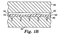
本発明によるマイクロニードルアレイを形成するための一実施形態を図1A〜Dに示す。簡潔には、図1Aに示されるように、本方法は、ネガ型キャビティ42の構造化表面14を画定するネガ型インサート44を提供することを含む。ネガ型キャビティ42の対向する表面16は、金型装置部材46によって画定される。構造化表面14は、所望のマイクロニードルおよび他の任意の特徴の形状を有するキャビティ40を具備する。図示されるように、対向する表面16は、構造化されていない又は平面状の表面である。代替の実施形態では、対向する表面16は、溝、スロット、ピンおよび針などのポジ形とネガ形の構造的特徴の両方を具有してもよい。
One embodiment for forming a microneedle array according to the present invention is shown in FIGS. Briefly, as shown in FIG. 1A, the method includes providing a
ポジ型マスター(図示せず)の周囲の電鋳プロセスにより、ネガ型インサート44を作製してもよい。電鋳プロセスは、マスターの特徴の周囲に金属を堆積させる電鋳タンクにポジ型マスターを入れることを含む。これは、例えば、ニッケルを含む任意の好適な金属であってもよい。ニッケルを所望の厚さに堆積させ、その時点で、電鋳された金属からポジ型マスターを分離し、所望のマイクロニードルアレイ用のネガ型マスター又はインサートを作り出す。この金型は、典型的には、電鋳金型(electroform)と呼ばれる。次いで、射出成形装置に嵌合するように、電鋳金型を所望の形状に切断する。
The
或いは、所望のマイクロニードルの形状のキャビティを提供するため、金型基材のレーザーアブレーション(例えば、エキシマレーザーを使用する)により、ネガ型インサート44を直接、作製してもよい。また、慣用的なフォトリソグラフィー、化学エッチング、イオンビームエッチング、又は、当該技術分野で既知の他の任意の慣用的なプロセスによりキャビティを形成してもよい。
Alternatively, the
図1Bに示されるように、次いで、ネガ型キャビティ42を、成形可能なプラスチック材料の軟化温度より約10℃高い温度より高い温度に加熱する。成形可能なプラスチック材料は、また、ネガ型キャビティとは別々のチャンバ(図示せず)内で、少なくとも、成形可能なプラスチック材料の溶融温度に加熱される。溶融プラスチック材料52を加熱されたネガ型キャビティ42の中に射出する。図示されるように、溶融プラスチック材料52は、ネガ型キャビティ42を部分的に充填している。図1Bは、本質的に概略的であり、部分的に充填された金型キャビティ内に存在する溶融材料は、表面14と16のどちらか又は両方に沿って存在してもよく、更に、それは金型の一方側からもう一方側まで(例えば、プラグとして)充填してもよいことを理解されたい。ネガ型インサート44および金型装置部材46の温度を制御するのに使用できるオイル加熱システムを使用して、ネガ型キャビティ42を加熱してもよい。溶融プラスチック材料は、好ましくは、ネガ型インサート44によって画成されるキャビティ40の容積の少なくとも約90%、更に好ましくは少なくとも約95%を充填する。一実施形態では、溶融プラスチック材料は、図1Cに示されるように、ネガ型インサート44によって画定されるキャビティ40の実質的に全容積を充填する。次いで、充填されたネガ型キャビティ42を、少なくとも、前記成形可能なプラスチック材料の軟化温度より低い温度に冷却する。最後に、図1Dに示されるように、成形されたマイクロニードルアレイ又はポジ型部材54をネガ型インサート44および金型装置46から取り外す。
As shown in FIG. 1B, the
好ましくは、成形されたマイクロニードルアレイは、ネガ型インサート内の対応するマイクロニードル形態の高さの約90%を超える高さを有する複数の成形されたマイクロニードルを備える。更に好ましくは、成形されたマイクロニードルアレイは、ネガ型インサート内の対応するマイクロニードル形態の高さの約95%を超える高さを有する複数の成形されたマイクロニードルを備える。成形されたマイクロニードルアレイは、ネガ型インサート内の対応するマイクロニードル形態の高さと実質的に同じ高さ(例えば、95%〜105%)を有する複数の成形されたマイクロニードルを備えることが最も好ましい。ネガ型インサートをプラスチック材料の軟化温度より高い温度に加熱すると、プラスチック材料は、マイクロニードルアレイのネガ像を形成するネガ型インサート内の狭いチャネルを実質的に充填することできる。狭いチャネルを充填する前に、プラスチック材料が実質的に冷却されないようにすることが重要であるが、それは、完全に充填する前にプラスチック材料がチャネル内で「被膜を形成し(skin over)」又は凝固し、溶融材料が更に流動することを阻止する可能性があるからである。 Preferably, the molded microneedle array comprises a plurality of molded microneedles having a height that is greater than about 90% of the height of the corresponding microneedle configuration in the negative insert. More preferably, the molded microneedle array comprises a plurality of molded microneedles having a height that is greater than about 95% of the height of the corresponding microneedle configuration in the negative insert. Most preferably, the molded microneedle array comprises a plurality of molded microneedles having substantially the same height (eg, 95% to 105%) as the height of the corresponding microneedle configuration in the negative insert. preferable. When the negative insert is heated to a temperature above the softening temperature of the plastic material, the plastic material can substantially fill the narrow channels in the negative insert forming a negative image of the microneedle array. It is important to ensure that the plastic material is not substantially cooled before filling the narrow channel, but it is “skin over” in the channel before it completely fills. Alternatively, it may solidify and prevent the molten material from flowing further.
「軟化温度」は、プラスチック材料が軟化し、通常の力(成形品が金型インサートから取り外される間に被る力など)が加わると変形する温度を指す。これは、(例えば、ASTM D1525−00に記載されるように、針にかかる50Nの荷重、および120℃/時間の昇温速度の条件で)平先針が試験サンプルに貫入する温度を測定するビカー軟化温度により簡便に測定され得る。非晶質材料では、軟化温度は、材料のガラス転移温度に支配され、場合によっては、ガラス転移温度は、ビカー軟化温度に本質的に等しい。ガラス転移温度は、示差走査熱量計などの当業者に既知の方法で10℃/分の典型的な走査速度を使用して測定され得る。好適な材料には、ポリスチレン、ポリ塩化ビニル、ポリメチルメタクリレート、アクリロニトリル−ブタジエンスチレン、およびポリカーボネートなどの、全ての熱可塑性樹脂および熱硬化性ポリマーが挙げられる。組成物のバルク特性が結晶性材料に支配される、結晶性材料と非晶質材料の両方を含む組成物では、軟化温度は、材料の溶融に支配され、ビカー軟化温度によって特徴付けられる場合がある。このような材料の例には、ポリプロピレン、ポリブチレンテレフタレート、ポリスチレン、ポリエチレン、ポリエーテルイミド、ポリエチレンテレフタレート、およびこれらのブレンドが挙げられる。 “Softening temperature” refers to a temperature at which a plastic material softens and deforms when a normal force (such as a force applied while a molded product is removed from a mold insert) is applied. This measures the temperature at which the flat needle penetrates the test sample (for example, as described in ASTM D1525-00, with a 50N load on the needle and a heating rate of 120 ° C./hour). It can be easily measured by the Vicat softening temperature. For amorphous materials, the softening temperature is governed by the glass transition temperature of the material, and in some cases, the glass transition temperature is essentially equal to the Vicat softening temperature. The glass transition temperature can be measured using a typical scan rate of 10 ° C./min in a manner known to those skilled in the art, such as a differential scanning calorimeter. Suitable materials include all thermoplastic resins and thermosetting polymers such as polystyrene, polyvinyl chloride, polymethyl methacrylate, acrylonitrile-butadiene styrene, and polycarbonate. In compositions containing both crystalline and amorphous materials where the bulk properties of the composition are dominated by the crystalline material, the softening temperature is dominated by the melting of the material and may be characterized by the Vicat softening temperature. is there. Examples of such materials include polypropylene, polybutylene terephthalate, polystyrene, polyethylene, polyetherimide, polyethylene terephthalate, and blends thereof.
一実施形態では、溶融プラスチック材料の射出前に、ネガ型キャビティ42を、成形可能なプラスチック材料の軟化温度より約20℃高い温度より高い温度に加熱する。別の実施形態では、溶融プラスチック材料の射出前に、ネガ型キャビティ42を、成形可能なプラスチック材料の軟化温度より約30℃高い温度より高い温度に加熱する。
In one embodiment, prior to injection of the molten plastic material, the
一実施形態では、成形されたマイクロニードルアレイ又はポジ型部材54をネガ型インサート44から取り外す前に、ネガ型キャビティ42を、成形可能なプラスチック材料の軟化温度より約5℃低い温度より低温に冷却する。別の実施形態では、成形されたマイクロニードルアレイ又はポジ型部材54をネガ型インサート44から取り外す前に、ネガ型キャビティ42を、成形可能なプラスチック材料の軟化温度より約10℃低い温度より低い温度に冷却する。
In one embodiment, before removing the molded microneedle array or
図2は、ネガ型キャビティ42を画成する射出成形装置の一部の詳細図を示す。ネガ型キャビティ42の構造化表面14は、ネガ型インサート44によって画成される。ネガ型キャビティ42の反対側の表面16は、金型装置46によって画成される。金型インサート支持ブロック124は、熱サイクルプロセス中、ネガ型インサート44への熱伝達を容易にする。金型インサートフレーム126は、ネガ型キャビティ42の側壁を画成し、金型インサート支持ブロック124およびネガ型インサート44を所定の場所に保持する。
FIG. 2 shows a detailed view of a portion of an injection molding apparatus that defines a
一実施形態では、ポジ型マスター部材を使用してネガ型インサートを形成する。ポジ型マスター部材は、マイクロニードルアレイが成形される形状に材料を形成することによって製造される。このマスターは、以下に限定されないが、銅、鋼、アルミニウム、真鍮、および、他の重金属を含む材料から機械加工することができる。マスターは、シリコーン型を使用して圧縮成形される熱可塑性又は熱硬化性ポリマーから製造することもできる。マスターは、所望のマイクロニードルアレイを直接複製するように製造される。例えば、ピラミッド、円錐、又はピンなどの様々な形状のいずれかを有する突起のある表面を形成するように金属シートをダイヤモンド旋削することを含む多数の方法でポジ型マスターを作製してもよい。ポジ型マスターの突起は、後で形成されるネガ型インサートを使用して成形する間に形成されるマイクロニードルアレイが、ポジ型マスターと実質的に同じ形態を有するように、適切なサイズと間隔に作られる。 In one embodiment, a positive master member is used to form a negative insert. The positive master member is manufactured by forming a material into a shape in which a microneedle array is formed. The master can be machined from materials including, but not limited to, copper, steel, aluminum, brass, and other heavy metals. The master can also be made from a thermoplastic or thermoset polymer that is compression molded using a silicone mold. The master is manufactured to replicate directly the desired microneedle array. For example, the positive master may be made in a number of ways, including diamond turning a metal sheet to form a raised surface having any of a variety of shapes such as pyramids, cones, or pins. The protrusions of the positive master are properly sized and spaced so that the microneedle array formed during molding using a negative insert that will be formed later has substantially the same shape as the positive master. Made to.
一実施形態では、ポジ型マスターは、ダイヤモンド旋削などの、米国特許第5,152,917号明細書(ピーパー(Pieper)ら)および米国特許第6,076,248号明細書(フープマン(Hoopman)ら)に開示されている直接機械加工技術により、作製される。例えば、ダイヤモンド旋盤の使用により、金属のポジ型マスター表面にマイクロニードルアレイを形成することができ、それからキャビティの形状の配列を有する生産用治工具又はネガ型インサートが製造される。アルミニウム、銅、又は真鍮などのダイヤモンド旋削に適する金属表面に所望の形状を残すようにダイヤモンド旋削した後、溝が形成された表面をニッケルめっきして金属マスターを提供することにより、金属のポジ型マスターを製造することができる。金属製の生産用治工具又はネガ型インサートは、ポジ型マスターから電鋳により製造することができる。これらの技術は、米国特許第6,021,559号明細書(スミス(Smith))に更に記載されている。 In one embodiment, the positive master is a U.S. Pat. No. 5,152,917 (Pieper et al.) And U.S. Pat. No. 6,076,248 (Hoopman), such as diamond turning. And so on) by the direct machining technique disclosed in For example, a diamond lathe can be used to form a microneedle array on a metal positive master surface, from which a production tool or negative insert is produced having an array of cavity shapes. After turning the diamond to leave the desired shape on the metal surface suitable for diamond turning, such as aluminum, copper, or brass, the grooved surface is nickel-plated to provide a metal master, thereby providing a positive metal type Master can be manufactured. A metal production jig or negative insert can be produced from a positive master by electroforming. These techniques are further described in US Pat. No. 6,021,559 (Smith).
一実施形態では、溶融プラスチック材料がネガ型キャビティを充填できるようにすることを助けるのに使用される充填(packing)又は射出圧力と共に、溶融プラスチック材料の射出を行ってもよい。一実施形態では、この圧力は、約6,000psiより大きくてもよい。別の実施形態では、この圧力は、約10,000psiより大きくてもよい。更に別の実施形態では、この圧力は、約20,000psiより大きくてもよい。 In one embodiment, the injection of molten plastic material may be performed with the packing or injection pressure used to help allow the molten plastic material to fill the negative cavity. In one embodiment, this pressure may be greater than about 6,000 psi. In another embodiment, this pressure may be greater than about 10,000 psi. In yet another embodiment, this pressure may be greater than about 20,000 psi.
一実施形態では、ネガ型キャビティの中に溶融プラスチック材料を射出してから、成形されたマイクロニードルアレイ取り外すまでの時間(即ち、「サイクル時間」)は、ネガ型キャビティに溶融材料を実質的に充填し、且つ、溶融プラスチック材料を後でその軟化点より低温に冷却することができるのに十分である。サイクル時間は、好ましくは約5分未満、更に好ましくは約3分未満、最も好ましくは約90秒未満である。 In one embodiment, the time between injection of molten plastic material into the negative cavity and removal of the molded microneedle array (ie, “cycle time”) is substantially equal to the molten material in the negative cavity. It is sufficient that it can be filled and the molten plastic material can later be cooled below its softening point. The cycle time is preferably less than about 5 minutes, more preferably less than about 3 minutes, and most preferably less than about 90 seconds.
一実施形態では、2004年12月7日に提出され、「マイクロニードルの成形方法」(METHOD OF MOLDING A MICRONEEDLE)と題された米国特許出願第60/634319号明細書(代理人整理番号第57961US002)に記載されるように、ネガ型インサートの微細で緻密なキャビティを充填することを助けるため、金型キャビティ内の溶融材料に圧縮力を加えることが望ましい場合がある。射出圧縮成形に関する更なる詳細は、米国特許第4,489,033号明細書(宇田(Uda)ら)、同第4,515,543号明細書(ハムナー(Hamner))および同第6,248,281号明細書(阿部(Abe)ら)に見出される。 In one embodiment, U.S. Patent Application No. 60 / 634,319 (Attorney Docket No. 57961US002) filed Dec. 7, 2004 and entitled "METHOD OF MOLDING A MICRONEEDLE". ), It may be desirable to apply a compressive force to the molten material in the mold cavity to help fill the fine and dense cavities of the negative mold insert. Further details regarding injection compression molding can be found in U.S. Pat. Nos. 4,489,033 (Uda et al.), 4,515,543 (Hamner) and 6,248. 281 (Abe et al.).
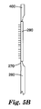
一実施形態では、成形装置は、図5Aおよび図5Bに示されるように、ネガ型キャビティ290に接続されるオーバーフローベント400を具備する。投入ライン280を通して供給される溶融プラスチック材料は、射出ゲート270を通過して金型キャビティ290に入る。矢印は、投入ライン280から金型キャビティ290へのポリマー材料の略流動方向を示す。ポリマー材料が金型キャビティを充填する時、ポリマー材料はキャビティ内にあった空気を排除する。一実施形態では、排除された空気は、金型キャビティ内、又は、金型インサートの中のマイクロニードルのネガ像内にあるポケットにほとんど又は全く捕捉されない。
In one embodiment, the molding apparatus comprises an
オーバーフローベント400は、排除された空気がキャビティから出て行くことを可能にする出口ゲートの役割をし、このようにして、金型キャビティにポリマー材料をより均一に充填することができる。オーバーフローベントは、金型キャビティの外面のどこに位置決めされてもよい。一実施形態では、オーバーフローベントは、金型キャビティの側壁に沿って位置決めされる。図5Aおよび5Bに示される実施形態では、オーバーフローベント400は、側壁に沿って位置決めされ、射出ゲート270の反対側にある。
The
図3を参照すると、各マイクロニードル12は、基材表面16上に底面20を具備し、マイクロニードルは基材表面より上で先端22となって終端する。図3に示されるマイクロニードルの底面20の形状は長方形であるが、マイクロニードル12およびそれに関連する底面20の形状はさまざまであってよく、底面には、例えば、1つ以上の方向に沿って細長いものもあれば、全方向で対称的なものもある。底面20は、正方形、長方形、又は楕円形などの任意の好適な形状に形成されてもよい。一実施形態では、底面20は、楕円形の形状(即ち、基材表面16上の伸長軸に沿って細長い)を有してもよい。
Referring to FIG. 3, each microneedle 12 has a
本発明のマイクロニードルを特徴付け得る方法の1つは、高さ26である。マイクロニードル12の高さ26は、基材表面16から測定されてもよい。例えば、マイクロニードル12の底面から先端までの高さは、基材表面16から測定するとき、約500マイクロメートル以下であることが好ましい場合がある。或いは、マイクロニードル12の高さ26は、底面20から先端22まで測定するとき、約250マイクロメートル以下であることが好ましい場合がある。また、成形されたマイクロニードルの高さは、ネガ型インサート内のマイクロニードル形態の高さの約90%を超え、更に好ましくは約95%を超えることが好ましい場合もある。マイクロニードルは、ネガ型インサートから突出す際、僅かに変形又は伸長する場合がある。この状態は、成形された材料がその軟化温度より低温に冷却されない場合、非常に顕著であるが、材料がその軟化温度より低温に冷却された後でも、まだ起こり得る。成形されたマイクロニードルの高さは、金型内のマイクロニードル形態の高さの約115%未満、更に好ましくは約105%未満であることが好ましい。
One method by which the microneedles of the present invention can be characterized is
本発明のマイクロニードルの全体形状には、先細になっている。例えば、マイクロニードル12は、より大きい底面20を基材表面16に有し、基材表面16から離れるように延び、先端22の方に先細になっている。一実施形態では、マイクロニードルの形状はピラミッド形である。別の実施形態では、マイクロニードルの形状は、略円錐形である。一実施形態では、マイクロニードルは、2003年7月17日に提出され「マイクロニードルデバイスおよびマイクロニードル送達装置」(MICRONEEDLE DEVICES AND MICRONEEDLE DELIVERY APPARATUS)と題された同時係属中の、本願特許出願人による米国特許出願第10/621620号明細書(代理人整理番号57901US005)に記載されているものなどの、画成された尖っていない先端を有し、該特許では、マイクロニードルは、底面と整列している平面で測定される表面積約20平方マイクロメートル以上、且つ100平方マイクロメートル以下の平坦な先端を有する。一実施形態では、平坦な先端の表面積は、底面と整列している平面で測定される断面積として測定され、その平面は、底面から0.98hの距離に位置し、ここでhは、底面から先端まで測定される、基材表面より上のマイクロニードルの高さである。
The overall shape of the microneedle of the present invention is tapered. For example, the
本発明に関連して使用されるマイクロニードルは、略垂直な側壁角を有してもよい、即ち、マイクロニードルは、マイクロニードルが突出する基材の表面にほぼ直交する側壁を有する、ピンの形態であってもよい。 The microneedles used in connection with the present invention may have a substantially vertical sidewall angle, i.e., the microneedles have a sidewall that is substantially perpendicular to the surface of the substrate from which the microneedles protrude. Form may be sufficient.
図4は、アレイ10の形態の、本発明の一実施形態による医療用デバイス示す。マイクロニードル12がマイクロニードル基材表面16から突出する状態で、アレイ10の一部が示されている。マイクロニードル12は、任意の所望のパターン14で配置されてもよく、又は基材表面16にランダムに分布してもよい。図示されるように、マイクロニードル12は、長方形の配置に置かれている均一に離間した列に配置されている。一実施形態では、本発明のアレイは、患者に面する表面積が、約0.1cm2より大きく、且つ約20cm2未満であり、好ましくは約0.5cm2より大きく、且つ約5cm2未満である。図4に示される実施形態では、基材表面16の一部は、パターン形成されていない。一実施形態では、パターン形成されていない表面の面積は、患者の皮膚表面に面するデバイス表面の全面積の約1%より大きく、且つ、約75%未満である。一実施形態では、パターン形成されていない表面の面積は、約0.10平方インチ(0.65cm2)より大きく、約1平方インチ(6.5cm2)未満である。別の実施形態(図示せず)では、マイクロニードルは、アレイ10の実質的に全表面積に配置される。
FIG. 4 shows a medical device according to an embodiment of the invention in the form of an
マイクロニードル基材は、様々な材料から製造されてもよい。材料の選択は、所望のパターンを正確に再現する材料の能力;マイクロニードルに形成されたときの材料の強度および靭性;材料と、例えば、ヒト又は動物の皮膚との適合性;材料と、マイクロニードルデバイスに接触することが予測される任意の流体との適合性などを含む様々な要因に基づいてもよい。 The microneedle substrate may be made from a variety of materials. The choice of material is the ability of the material to accurately reproduce the desired pattern; the strength and toughness of the material when formed into microneedles; the compatibility of the material with, for example, human or animal skin; the material and the micro It may be based on a variety of factors including compatibility with any fluid expected to contact the needle device.
ポリマー材料の中でも、マイクロニードルは熱可塑性ポリマー材料で製造されることが好ましい。本発明のマイクロニードルに好適なポリマー材料には、以下に限定されないが、ポリフェニルスルフィド、ポリカーボネート、ポリプロピレン、アセタール、アクリル、ポリエーテルイミド、ポリブチレンテレフタレート、ポリエチレンテレフタレートなどが挙げられる。ポリマーマイクロニードルは、単一のポリマー又は2種類以上のポリマーの混合物/ブレンドで製造されてもよい。好ましい実施形態では、マイクロニードルは、ポリカーボネートから形成される。別の好ましい実施形態では、マイクロニードルは、ポリカーボネートとポリエーテルイミドとのブレンドから形成される。更に別の好ましい実施形態では、マイクロニードルは、ポリカーボネートとポリエチレンテレフタレートとのブレンドから形成される。 Among the polymer materials, the microneedles are preferably made of a thermoplastic polymer material. Polymer materials suitable for the microneedles of the present invention include, but are not limited to, polyphenyl sulfide, polycarbonate, polypropylene, acetal, acrylic, polyetherimide, polybutylene terephthalate, polyethylene terephthalate, and the like. The polymer microneedles may be made of a single polymer or a mixture / blend of two or more polymers. In a preferred embodiment, the microneedles are formed from polycarbonate. In another preferred embodiment, the microneedles are formed from a blend of polycarbonate and polyetherimide. In yet another preferred embodiment, the microneedles are formed from a blend of polycarbonate and polyethylene terephthalate.
ポリマー材料は、以下の特性、即ち、高い破断点引長伸び、高い衝撃強さ、および高いメルトフローインデックスのうち1つ以上を有することが好ましい場合がある。一態様では、ASTM D1238(条件:300℃、重量1.2kg)で測定するときメルトフローインデックスは、約5g/10分より大きい。ASTM D1238(条件:300℃、重量1.2kg)で測定するときメルトフローインデックスは、好ましくは約10g/10分より大きく、更に好ましくは約20g/10分〜30g/10分である。一態様では、ASTM D638(2.0インチ/分)で測定するとき破断点引張伸びは、約100%より大きい。一態様では、ASTM D256、「ノッチ付きアイゾッド」(73°F)で測定するとき衝撃強さは、約5フィート・ポンド/インチより大きい。 The polymeric material may preferably have one or more of the following properties: high elongation at break, high impact strength, and high melt flow index. In one aspect, the melt flow index is greater than about 5 g / 10 minutes as measured by ASTM D1238 (conditions: 300 ° C., weight 1.2 kg). When measured by ASTM D1238 (conditions: 300 ° C., weight 1.2 kg), the melt flow index is preferably greater than about 10 g / 10 min, more preferably from about 20 g / 10 min to 30 g / 10 min. In one aspect, the tensile elongation at break is greater than about 100% as measured by ASTM D638 (2.0 inches / minute). In one aspect, the impact strength is greater than about 5 ft. Pounds / inch as measured by ASTM D256, “Notched Izod” (73 ° F.).
本発明のマイクロニードルデバイスのマイクロニードルを特徴付け得る別の方法は、マイクロニードルのアスペクト比に基づいている。本明細書で使用するとき、「アスペクト比」の用語は、(マイクロニードルの底面を取り囲む表面より上の)マイクロニードルの高さと最大底面寸法、即ち、(マイクロニードルの底面が占める表面で)底面が占める最長直線寸法との比である。図3に見られるように、長方形の底面20を有するピラミッド形マイクロニードルの場合、最大底面寸法は、底面20を横切って反対側にある角を接続する対角線である。一実施形態では、マイクロニードルは、2:1以上のアスペクト比を有する。一実施形態では、マイクロニードルは、約3:1のアスペクト比を有する。一実施形態では、マイクロニードルは、約2:1〜約5:1のアスペクト比を有する。
Another way in which the microneedles of the microneedle device of the present invention can be characterized is based on the aspect ratio of the microneedles. As used herein, the term “aspect ratio” refers to the height and maximum bottom dimension of a microneedle (above the surface surrounding the bottom surface of the microneedle), ie, the bottom surface (in the surface occupied by the bottom surface of the microneedle). Is the ratio to the longest linear dimension occupied by. As seen in FIG. 3, for a pyramidal microneedle having a
本発明の様々な実施形態に有用なマイクロアレイは、様々な構成のどれを備えてもよい。図示されていないが、マイクロニードルデバイスは、米国特許出願公開第2003−0045837−A1に記載されているチャネルなどの、他の特徴を具備してもよい。前述の特許出願に開示されている微細構造は、各マイクロニードルの外面に形成された少なくとも1つのチャネルを具備する、先細の構造を有するマイクロニードル形態である。マイクロニードルは、一方向に細長い底面を有してもよい。細長い底面を有するマイクロニードル内のチャネルは、細長い底面の端部の一方からマイクロニードルの先端の方に延びてもよい。マイクロニードルの側面に沿って形成されるチャネルは、任意に、マイクロニードルの先端に達しないで終端してもよい。マイクロニードルアレイは、また、マイクロニードルアレイが配置される基材の表面に形成されるコンジット構造を具備してもよい。マイクロニードル内のチャネルは、コンジット構造と流体連通していてもよい。 Microarrays useful in various embodiments of the invention may have any of a variety of configurations. Although not shown, the microneedle device may have other features, such as the channel described in US Patent Application Publication No. 2003-0045837-A1. The microstructure disclosed in the aforementioned patent application is in the form of a microneedle having a tapered structure with at least one channel formed on the outer surface of each microneedle. The microneedle may have an elongated bottom surface in one direction. A channel in the microneedle having an elongated bottom surface may extend from one of the ends of the elongated bottom surface toward the tip of the microneedle. The channel formed along the side of the microneedle may optionally terminate without reaching the tip of the microneedle. The microneedle array may also include a conduit structure formed on the surface of the substrate on which the microneedle array is disposed. The channel in the microneedle may be in fluid communication with the conduit structure.
マイクロアレイの別の実施形態は、皮膚を穿刺するための刃状の微細突起を記載している米国特許第6,091,975号明細書(ダドナ(Daddona)ら)に開示されている構造を備える。マイクロアレイの更に別の実施形態は、中空の中心チャネルを有する先細の構造を記載している米国特許第6,313,612号明細書(シャーマン(Sherman)ら)に開示されている構造を備える。マイクロアレイの更に別の実施形態は、マイクロニードルの先端の頂部表面に少なくとも1つの縦刃を有する中空のマイクロニードルを記載している米国特許第6,652,478号明細書(ガルトシュタイン(Gartstein)ら)に開示されている構造を備える。 Another embodiment of the microarray comprises the structure disclosed in US Pat. No. 6,091,975 (Daddona et al.) Describing blade-like microprojections for puncturing the skin. . Yet another embodiment of the microarray comprises the structure disclosed in US Pat. No. 6,313,612 (Sherman et al.) Which describes a tapered structure having a hollow central channel. Yet another embodiment of a microarray is US Pat. No. 6,652,478 (Gartstein) which describes a hollow microneedle having at least one vertical blade on the top surface of the tip of the microneedle. Et al.).
本明細書に記載の例証のマイクロニードルデバイスは、複数のマイクロニードルを具備してもよいが、本発明のマイクロニードルデバイスは、各基材上にマイクロニードルを1つしか具備しなくてもよい。更に、マイクロニードルデバイスは全て、基材を1つしか有していないように図示されているが、各デバイスは、各基材がそれから突出するマイクロニードルを1つ以上具備する、複数の基材を具備することができる。アレイをアプリケータに可逆的に取り付ける手段を有するアレイを具備する好適な一体型(one−piece)構成が、2003年12月29日に提出され、「医療用デバイスおよび同を具備するキット」(MEDICAL DEVICES AND KITS INCLUDING SAME)と題された、本願特許出願人による係属中の米国特許出願第60/532987号明細書(代理人整理番号59402US002)に記載されている。 The illustrated microneedle device described herein may comprise a plurality of microneedles, but the microneedle device of the present invention may comprise only one microneedle on each substrate. . Further, although all the microneedle devices are illustrated as having only one substrate, each device includes a plurality of substrates, each substrate having one or more microneedles protruding therefrom. Can be provided. A suitable one-piece configuration comprising an array having means for reversibly attaching the array to the applicator was filed on Dec. 29, 2003, entitled “Medical devices and kits comprising the same” ( US patent application Ser. No. 60/532987 (Attorney Docket No. 59402US002), pending from the present applicant, entitled MEDICAL DEVICES AND KITS INCLUDING SAME).
本発明のマイクロニードルデバイスは、多数の薬物および治療指示(therapeutic indication)に有用となり得る。一態様では、分子量の大きい薬物を経皮的に送達し得る。分子量が増大すると典型的には、補助なしの又は受動的な経皮送達は低減することが一般に認められている。本発明のマイクロニードルデバイスは、受動的経皮送達による送達が通常は困難又は不可能な大分子の送達に有用である。このような大分子の例には、蛋白質、ペプチド、ワクチン、ワクチンアジュバント、多糖類(ヘパリンなど)、および抗生物質(セフトリアキソンなど)が挙げられる。 The microneedle device of the present invention can be useful for a number of drugs and therapeutic indications. In one aspect, a high molecular weight drug can be delivered transdermally. It is generally accepted that increasing the molecular weight typically reduces unassisted or passive transdermal delivery. The microneedle device of the present invention is useful for the delivery of large molecules that are normally difficult or impossible to deliver by passive transdermal delivery. Examples of such large molecules include proteins, peptides, vaccines, vaccine adjuvants, polysaccharides (such as heparin), and antibiotics (such as ceftriaxone).
別の態様では、本発明のマイクロニードルデバイスは、受動的経皮送達による送達が他の方法では困難又は不可能な小分子の経皮送達を向上させる又は可能にするのに有用となり得る。このような分子の例には、塩の形態;アレンドロン酸ナトリウム又はパメドロン酸ナトリウムなどのビホスホネートを含むイオン性分子;および、受動的経皮送達の助けとならない物理化学的特性を有する分子が挙げられる。 In another aspect, the microneedle device of the present invention may be useful to improve or enable transdermal delivery of small molecules that are otherwise difficult or impossible to deliver by passive transdermal delivery. Examples of such molecules include salt forms; ionic molecules including biphosphonates such as sodium alendronate or sodium pamedronate; and molecules with physicochemical properties that do not aid in passive transdermal delivery. Can be mentioned.
別の態様では、本発明のマイクロニードルデバイスは、受動的経皮送達を使用して送達され得る分子(ニトログリセリン又はエストラジオールなど)の経皮送達を向上させる又は変更するのに有用となり得る。このような場合、マイクロニードルデバイスは、補助なしの受動的送達と比較してより迅速な送達開始を引き起こすために、又は増大した流れを引き起こすために使用され得る。 In another aspect, the microneedle device of the present invention can be useful for improving or modifying transdermal delivery of molecules (such as nitroglycerin or estradiol) that can be delivered using passive transdermal delivery. In such cases, the microneedle device can be used to cause a faster onset of delivery compared to passive delivery without assistance or to cause increased flow.
別の態様では、本発明のマイクロニードルデバイスは、皮膚科学的治療又はワクチンアジュバントの免疫応答を向上させる際などに、皮膚への分子の送達を向上させるために有用となり得る。 In another aspect, the microneedle device of the present invention may be useful for improving the delivery of molecules to the skin, such as in improving the immune response of a dermatological treatment or vaccine adjuvant.
本発明のマイクロニードルアレイは、様々な異なる方法で使用され得る。本発明のマイクロニードルアレイの使用法の1つは、薬剤又は他の物質を送達するため、および/又は、皮膚を通して血液又は組織を抽出するために皮膚を貫通することを含む。使用する際、一般に、角質層を貫通するのに十分な高さでアレイの微細構造を提供することが望ましい。薬剤又は治療剤を送達するとき、典型的には剤を皮膚の一領域に直接塗布し、次いで、角質層を穿刺するのに十分な力で皮膚にアレイの微細構造を接触させることによりアレイを皮膚の同じ領域に適用し、それによって、治療剤は皮膚の最外層を通って体内に入ることができる。本発明の医療用デバイスを使用する治療剤の送達のパラメータは、前述の米国特許出願公開第2003−0045837−A1号明細書および同時係属中の特許出願第10/621620号明細書に好適に記載されている。 The microneedle array of the present invention can be used in a variety of different ways. One use of the microneedle array of the present invention involves penetrating the skin to deliver drugs or other substances and / or to extract blood or tissue through the skin. In use, it is generally desirable to provide the microstructure of the array at a height sufficient to penetrate the stratum corneum. When delivering an agent or therapeutic agent, the array is typically applied by applying the agent directly to a region of the skin and then bringing the array microstructure into contact with the skin with sufficient force to puncture the stratum corneum. Applied to the same area of the skin, whereby the therapeutic agent can enter the body through the outermost layer of the skin. Parameters for delivery of therapeutic agents using the medical device of the present invention are suitably described in the aforementioned US Patent Application Publication No. 2003-0045837-A1 and co-pending patent application No. 10/621620. Has been.
実施例1〜12
前述の概略的な手順に従い、熱サイクル装置(レゴプラス301DG熱サイクル装置(Regoplas 301 DG Thermal Cycling Unit))を装備した55トンの射出成形機(ミラコン・シンシナティACT D−シリーズ射出成形機(Milacon Cincinnati ACT D−Series Injection Molding Press))を使用して、成形されたマイクロニードルアレイを作製した。ポリカーボネートペレットを往復スクリュに投入し、溶融するまで加熱した。ネガ型インサートを、成形される材料の軟化温度より高い特定の温度(以下、「射出時の金型温度(“mold temperature at injection”)」と称する)に加熱した。金型チャンバを閉鎖し、55トンの力で型締めし、材料の総量の第1の部分(成形品の寸法容積の約50〜80%)を往復スクリュからネガ型インサートの中に射出することにより、成形サイクルを開始した。材料の第1の部分をネガ型インサートの中に一定の速度(以下、「射出速度」と称する)で射出した。材料の第1の部分を射出した後、一定の圧力(以下、「充填圧力(“pack pressure”)」と称する)を加えて溶融材料の残りをネガ型インサートに押し入れることにより、プロセスを射出運転モードから圧力運転モードに転換した。一定時間(以下、「保圧時間(hold time)」と称する)、充填圧力を加えた。その後、充填圧力を解放し、成形された材料の軟化温度以下であった突出し温度(以下、「突出し時の金型温度」と称する)にネガ型インサートを冷却した。次いで、金型チャンバを開放し、成形品を突出した。各例に使用した射出速度、充填圧力、保圧時間、射出温度、および突出し温度の詳細を表1に記載する。
Examples 1-12
A 55 ton injection molding machine (Milacon Cincinnati ACT D-series injection molding machine (Milacon Cincinnati ACT) equipped with a thermal cycler (Legoplus 301 DG Thermal Cycling Unit) according to the general procedure described above. D-Series Injection Molding Press) was used to make a molded microneedle array. Polycarbonate pellets were placed in a reciprocating screw and heated until melted. The negative mold insert was heated to a specific temperature above the softening temperature of the material to be molded (hereinafter referred to as “mold temperature at injection”). Close the mold chamber, clamp with a force of 55 tons, and inject the first part of the total amount of material (approximately 50-80% of the dimensional volume of the part) from the reciprocating screw into the negative mold insert. The molding cycle was started. The first part of the material was injected into the negative insert at a constant speed (hereinafter referred to as “injection speed”). After injecting the first part of the material, the process is injected by applying a certain pressure (hereinafter referred to as “pack pressure”) and pushing the remainder of the molten material into the negative insert. Switched from operation mode to pressure operation mode. The filling pressure was applied for a certain period of time (hereinafter referred to as “hold time”). Thereafter, the filling pressure was released, and the negative insert was cooled to a protruding temperature (hereinafter referred to as “mold temperature at the time of protruding”) that was not higher than the softening temperature of the molded material. Next, the mold chamber was opened and the molded product was protruded. Details of the injection speed, filling pressure, holding time, injection temperature, and protrusion temperature used in each example are listed in Table 1.
ポリカーボネート(マクロロン(Makrolon)(登録商標)2407、バイエルポリマー(Bayer Polymers))は、以下の材料特性、1)ASTM D1238に従い300℃および1.2kgの条件で測定するときのメルトフローインデックス、20g/10分;2)ASTM D638に従い1mm/分の速度で測定するときの引張弾性率、350,000psi(2400Mpa);3)ASTM D638に従い1mm/分の速度で測定するときの降伏点引張応力、9400psi(64Mpa);4)ASTM D638に従い1mm/分の速度で測定するときの破断点引張伸び、115%;5)ASTM D1822に従い73°F(23℃)で測定するときのノッチ付きアイゾッド衝撃強さ、14フィート・ポンド/平方インチ(29.4kj/m2);6)120℃/時間の速度で測定するビカー軟化温度、146℃:を有した。 Polycarbonate (Macrolon® 2407, Bayer Polymers) has the following material properties: 1) Melt flow index when measured at 300 ° C. and 1.2 kg according to ASTM D1238, 20 g / 10 minutes; 2) Tensile modulus as measured at a rate of 1 mm / min according to ASTM D638, 350,000 psi (2400 Mpa); 3) Tensile stress at yield point as measured at a rate of 1 mm / min according to ASTM D638, 9400 psi (64 Mpa); 4) Tensile elongation at break when measured at a rate of 1 mm / min according to ASTM D638, 115%; 5) Izod impact strength with notch when measured at 73 ° F. (23 ° C.) according to ASTM D1822 , 14 feet pong / Square inch (29.4kj / m 2); 6 ) Vicat softening temperature is measured at a rate of 120 ° C. / time, 146 ° C.: had.
マイクロニードルアレイのネガ像は、以下の寸法を有した。アレイ全体の形状は正方形であり、直径0.375インチ(0.95cm)であった。各アレイの個々の針の形状はピラミッド形であり、高さ150ミクロン、底面の辺の長さ50ミクロンであり、従って、針のアスペクト比は3:1であった。針は、隣接する針の先端間の距離が200ミクロンの規則的な配列になるように離間された。先端は、平坦な頂部の辺の長さが5ミクロンである切頭先端を有した。ネガ型インサートは3つのアレイを製造するように構成され、それらは、全長2.7インチ(6.86cm)、幅0.82インチ(2.08cm)、および厚さ0.062インチ(0.157cm)の1つの成形品に含まれた。次いで、これらのアレイを特定の直径に切断した。 The negative image of the microneedle array had the following dimensions: The overall array shape was square with a diameter of 0.375 inches (0.95 cm). The shape of the individual needles in each array was pyramidal, with a height of 150 microns and a base side length of 50 microns, so the needle aspect ratio was 3: 1. The needles were spaced so that the distance between adjacent needle tips was a regular array of 200 microns. The tip had a truncated tip with a flat top side length of 5 microns. The negative insert is configured to produce three arrays, which are 2.7 inches (6.86 cm) long, 0.82 inches (2.08 cm) wide, and 0.062 inches thick (0. 0 cm). 157 cm). These arrays were then cut to specific diameters.
各例についての射出速度、充填圧力、保圧時間、射出時の金型温度、突出し時の金型温度、および得られる針の高さの詳細を表1に示す。得られるアレイの断面を切断し、立体顕微鏡で観察することによってマイクロニードルの高さを測定した。測定は、9回の測定(各個々のアレイから3回)の平均として行った。 Table 1 shows details of the injection speed, filling pressure, holding time, mold temperature during injection, mold temperature during protrusion, and needle height obtained for each example. The cross section of the resulting array was cut and the height of the microneedles was measured by observing with a stereo microscope. Measurements were made as an average of 9 measurements (3 from each individual array).
実施例C1〜C2
各アレイの射出時の金型温度をそれぞれ310°F(154.4℃)と260°F(126.7℃)に下げたことを例外として、実施例1〜12に記載される手順に従い、成形されたマイクロニードルアレイを作製した。各例についての射出速度、充填圧力、保圧時間、射出時の金型温度、突出し時の金型温度、および得られた針の高さの比較例の詳細を表1に示す。
Examples C1-C2
According to the procedures described in Examples 1-12, with the exception that the mold temperature during injection of each array was reduced to 310 ° F. (154.4 ° C.) and 260 ° F. (126.7 ° C.), respectively. A molded microneedle array was produced. Table 1 shows details of comparative examples of injection speed, filling pressure, holding time, mold temperature during injection, mold temperature during protrusion, and needle height obtained for each example.

実施例13〜16
各アレイの個々の針が、高さ375ミクロン、底面の辺の長さ125ミクロンであったことを例外として、実施例1〜12に記載される手順に従い、成形されたマイクロニードルアレイを作製した。隣接する針の先端間の距離が600ミクロンの規則的な配列になるように針を離間させた。各例に使用した射出速度、充填圧力、保圧時間、射出時の金型温度、および突出し時の金型温度の詳細を表2に示す。
Examples 13-16
Molded microneedle arrays were made according to the procedures described in Examples 1-12, with the exception that the individual needles in each array were 375 microns in height and 125 microns in length on the bottom side. . The needles were spaced so that the distance between adjacent needle tips was a regular array of 600 microns. Table 2 shows details of the injection speed, filling pressure, holding time, mold temperature during injection, and mold temperature during ejection used in each example.
実施例17〜26
使用した材料が、以下の材料特性、1)ASTM D1238に従い337℃および6.6kgの条件で測定するときのメルトフローインデックス、17.8g/10分;2)ASTM D638に従い0.2mm/分の速度で測定するときの引張弾性率、520,000psi(3540Mpa);3)ASTM D638に従い0.2mm/分の速度で測定するときの降伏点引張応力、16000psi(110Mpa);4)ASTM D638に従い0.2mm/分の速度で測定するときの破断点引張伸び、60%;5)ASTM D256、ノッチ付きアイゾッドに従い、73°F(23℃)で測定するときの衝撃強さ、0.6フィート・ポンド/平方インチ(1.3kj/m2);6)120℃/時間の速度で測定するビカー軟化温度、219℃:を有するポリエーテルイミド(ウルテム(Ultem)(登録商標)1010、GEプラスチックス(GE Plastics))であったことを例外として、実施例1〜12に記載される手順に従い、成形されたマイクロニードルアレイを作製した。各例に使用した射出速度、充填圧力、保圧時間、射出時の金型温度、および突出し時の金型温度の詳細を表3に記載する。
Examples 17-26
The materials used have the following material properties: 1) Melt flow index when measured at 337 ° C. and 6.6 kg according to ASTM D1238, 17.8 g / 10 min; 2) 0.2 mm / min according to ASTM D638 Tensile modulus as measured at speed, 520,000 psi (3540 Mpa); 3) Yield point tensile stress as measured at a rate of 0.2 mm / min according to ASTM D638, 16000 psi (110 Mpa); 4) 0 according to ASTM D638 . Tensile elongation at break when measured at a speed of 2 mm / min, 60%; 5) Impact strength measured at 73 ° F (23 ° C) according to ASTM D256, notched Izod, 0.6 ft · Pounds per square inch (1.3 kj / m 2 ); 6) Vicat softening temperature measured at a rate of 120 ° C./hour, Molded according to the procedure described in Examples 1-12, with the exception that it was a polyetherimide (Ultem® 1010, GE Plastics) with 219 ° C. A microneedle array was prepared. Details of the injection speed, filling pressure, holding time, mold temperature during injection, and mold temperature during ejection used in each example are shown in Table 3.
実施例C3
アレイの射出時の金型温度を330°F(165.6℃)に下げたことを例外として、実施例17〜26に記載される手順に従い、成形されたマイクロニードルアレイを作製した。突出し時の金型温度も330°F(165.6℃)に下げた。各例についての射出速度、充填圧力、保圧時間、射出時の金型温度、突出し時の金型温度、および得られた針の高さの比較例の詳細を表3に示す。
Example C3
Molded microneedle arrays were made according to the procedures described in Examples 17-26, with the exception that the mold temperature during array injection was reduced to 330 ° F. (165.6 ° C.). The mold temperature during protrusion was also reduced to 330 ° F. (165.6 ° C.). Table 3 shows details of comparative examples of injection speed, filling pressure, holding time, mold temperature during injection, mold temperature during protrusion, and needle height obtained for each example.
実施例27〜28
使用した材料が、以下の材料特性、1)ASTM D1238に従い337℃および6.6kgの条件で測定するときのメルトフローインデックス、24g/10分;2)ASTM D638に従い0.2mm/分の速度で測定するときの降伏点引張応力、14000psi(95Mpa);3)ASTM D638に従い0.2mm/分の速度で測定するときの破断点引張伸び、70%;5)ASTM D256、ノッチ付きアイゾッドに従い、73°F(23℃)で測定するときの衝撃強さ、1フィート・ポンド/平方インチ(2.1kj/m2):を有するポリエーテルイミドとポリカーボネートとのブレンド(ウルテム(Ultem)(登録商標)ATX200、GEプラスチックス(GE Plastics))であったことを例外として、実施例1〜12に記載される手順に従い、成形されたマイクロニードルアレイを作製した。各例に使用した射出速度、充填圧力、保圧時間、射出時の金型温度、および突出し時の金型温度の詳細を表4に記載する。
Examples 27-28
The materials used have the following material properties: 1) Melt flow index when measured at 337 ° C. and 6.6 kg according to ASTM D1238, 24 g / 10 min; 2) at a rate of 0.2 mm / min according to ASTM D638 Yield point tensile stress as measured, 14000 psi (95 Mpa); 3) Tensile elongation at break as measured at a rate of 0.2 mm / min according to ASTM D638, 70%; 5) ASTM D256, according to notched Izod 73 Polyetherimide and polycarbonate blends (Ultem®) having an impact strength, measured in ° F (23 ° C), 1 ft lb / in 2 (2.1 kj / m 2 ): With the exception of ATX200, GE Plastics) According to the procedures described in Examples 1 to 12, molded microneedle arrays were produced. Details of the injection speed, filling pressure, holding time, mold temperature during injection, and mold temperature during ejection used in each example are shown in Table 4.
実施例29
2つのことを例外として、実施例1〜12に記載される手順に従い、成形されたマイクロニードルアレイを作製した。充填圧力は、初期保圧時間では第1の値(21000psi)に設定し、次いで、第2の保圧時間では第2の値(18000psi)に下げた。更に、使用した材料は、以下の材料特性、1)ASTM D1238に従い300℃および1.2kgの条件で測定するときのメルトフローインデックス、10.5g/10分;2)ASTM D638に従い2.0mm/分の速度で測定するときの引張弾性率、237,000psi(1610Mpa);3)ASTM D638に従い2.0mm/分の速度で測定するときの降伏点引張応力、6600psi(45Mpa);4)ASTM D638に従い2.0mm/分の速度で測定するときの破断点引張伸び、150%;5)ASTM D256、ノッチ付きアイゾッドに従い、73°F(23℃)で測定するときの衝撃強さ、15フィート・ポンド/インチ(31.5kj/m2);6)120℃/時間の速度で測定するビカー軟化温度、106℃:を有するポリエチレンテレフタレートとポリカーボネートとのブレンド(キシレックス(Xylex)(登録商標)X7110、GEプラスチックス(GE Plastics))であった。この例に使用した射出速度、充填圧力、保圧時間、射出時の金型温度、および突出し時の金型温度の詳細を表5に記載する。
Example 29
Molded microneedle arrays were made according to the procedures described in Examples 1-12 with two exceptions. The fill pressure was set to the first value (21000 psi) for the initial hold time and then lowered to the second value (18000 psi) for the second hold time. In addition, the materials used were the following material properties: 1) Melt flow index when measured at 300 ° C. and 1.2 kg in accordance with ASTM D1238, 10.5 g / 10 min; 2) 2.0 mm / in accordance with ASTM D638 Tensile modulus as measured at a rate of minutes, 237,000 psi (1610 Mpa); 3) Yield point tensile stress as measured at a rate of 2.0 mm / min according to ASTM D638, 6600 psi (45 Mpa); 4) ASTM D638 According to ASTM D256, notched Izod, impact strength when measured at 73 ° F. (23 ° C.), 15 feet. Pounds per inch (31.5 kj / m 2 ); 6) Vicat softening temperature measured at a rate of 120 ° C./hour, A blend of polyethylene terephthalate and polycarbonate having a temperature of 106 ° C. (Xylex® X7110, GE Plastics). Details of the injection speed, filling pressure, holding time, mold temperature during injection, and mold temperature during ejection used in this example are listed in Table 5.
当業者には、前述の詳細な説明は、医療用デバイス(例えば、アレイ)の究極的な製造を制限するものと解釈されるべきではないことが分かる。前述の実施形態は、本発明の範囲内にあると考えられる構造を例示するが、網羅的なものではない。従い、全ての数字は、「約」の用語によって緩和されるものと仮定する。 Those skilled in the art will appreciate that the foregoing detailed description should not be construed as limiting the ultimate manufacture of medical devices (eg, arrays). The foregoing embodiments illustrate structures that are considered to be within the scope of the invention, but are not exhaustive. Thus, all numbers are assumed to be relaxed by the term “about”.
本明細書に引用される全ての特許、特許出願、および出版物は、それぞれ、参照により個々に組み込まれるかのごとく、参照によりその内容全体が本明細書に組み込まれる。本発明の様々な変更および変形は、本発明の範囲を逸脱することなく当業者に明らかであり、本発明は、前述の例証の実施形態に不当に限定されるものではないことを理解されたい。 All patents, patent applications, and publications cited herein are hereby incorporated by reference in their entirety as if each were individually incorporated by reference. It should be understood that various modifications and variations of the present invention will be apparent to those skilled in the art without departing from the scope of the invention, and the invention is not unduly limited to the embodiments illustrated above. .
Claims (30)
前記ネガ型インサートを射出成形装置に移す工程であって、前記ネガ型インサートが露出し、ネガ型キャビティの構造化表面を画定する工程、
前記ネガ型キャビティを成形可能なプラスチック材料の軟化温度より高い温度に加熱する工程、
前記ネガ型キャビティとは別々のチャンバ内で、前記成形可能なプラスチック材料を、少なくとも、前記成形可能なプラスチック材料の溶融温度に加熱する工程、
前記溶融プラスチック材料を前記加熱したネガ型キャビティの中に射出する工程、
前記溶融プラスチック材料を、前記ネガ型インサートによって画定されるネガ形の窪みの容積の少なくとも約90%に充填させる工程、
前記溶融プラスチック材料を、前記成形可能なプラスチック材料の軟化温度より低い温度に冷却する工程、および、
前記成形されたマイクロニードルアレイを前記ネガ型インサートから取り外す工程、
を含む、成形されたマイクロニードルアレイの製造方法。 Providing a negative insert characterized by a negative image in the form of a microneedle, wherein at least one negative image of the microneedle is characterized by an aspect ratio of about 2: 1 to about 5: 1;
Transferring the negative mold insert to an injection molding apparatus, wherein the negative mold insert is exposed and defines a structured surface of the negative mold cavity;
Heating the negative cavity to a temperature higher than the softening temperature of the moldable plastic material;
Heating the moldable plastic material to at least the melting temperature of the moldable plastic material in a chamber separate from the negative cavity;
Injecting the molten plastic material into the heated negative cavity;
Filling the molten plastic material to at least about 90% of the volume of the negative recess defined by the negative insert;
Cooling the molten plastic material to a temperature below the softening temperature of the moldable plastic material; and
Removing the molded microneedle array from the negative insert;
A method for producing a molded microneedle array, comprising:
前記ネガ型インサートを射出成形装置に移す工程であって、前記ネガ型インサートが露出し、ネガ型キャビティの構造化表面を画定する工程、
前記ネガ型キャビティを成形可能なプラスチック材料の軟化温度より約10℃高い温度よりも高い温度に加熱する工程、
前記ネガ型キャビティとは別々のチャンバ内で、前記成形可能なプラスチック材料を、少なくとも、前記成形可能なプラスチック材料の溶融温度に加熱する工程、
前記溶融プラスチック材料を前記加熱したネガ型キャビティの中に射出する工程、
前記溶融プラスチック材料を、前記ネガ型インサートによって画定されるネガ形の窪みの容積の少なくとも約90%に充填させる工程、
前記溶融プラスチック材料を、少なくとも、前記成形可能なプラスチック材料の軟化温度より低い温度に冷却する工程、および、
前記成形されたマイクロニードルアレイを前記ネガ型インサートから取り外す工程、
を含む、成形されたマイクロニードルアレイの製造方法。 Providing a negative insert characterized by a negative image in the form of a microneedle, wherein at least one negative image of the microneedle is characterized by an aspect ratio of about 2: 1 to about 5: 1;
Transferring the negative mold insert to an injection molding apparatus, wherein the negative mold insert is exposed and defines a structured surface of the negative mold cavity;
Heating the negative cavity to a temperature higher than the softening temperature of the moldable plastic material by about 10 ° C .;
Heating the moldable plastic material to at least the melting temperature of the moldable plastic material in a chamber separate from the negative cavity;
Injecting the molten plastic material into the heated negative cavity;
Filling the molten plastic material to at least about 90% of the volume of the negative recess defined by the negative insert;
Cooling the molten plastic material to at least a temperature lower than the softening temperature of the moldable plastic material; and
Removing the molded microneedle array from the negative insert;
A method for producing a molded microneedle array, comprising:
マイクロニードル形態を特徴とするポジ型マスター部材を提供する工程であって、少なくとも1つのマイクロニードルが約2:1〜約5:1のアスペクト比を特徴とする工程、
前記ポジ型マスターの周囲にネガ型インサートを電鋳する工程、および
前記ネガ型インサートを前記ポジ型マスター部材から取り外す工程、
により形成される、請求項1又は2に記載の方法。 The negative insert is
Providing a positive master member characterized by a microneedle configuration, wherein at least one microneedle is characterized by an aspect ratio of about 2: 1 to about 5: 1;
Electroforming a negative insert around the positive master, and removing the negative insert from the positive master member;
The method according to claim 1, wherein the method is formed by:
前記ポジ型マスターの周囲にネガ型インサートを電鋳する工程、および
前記ネガ型インサートを前記ポジ型マスター部材から取り外す工程、
を含む、成形されたマイクロニードルアレイの作製に使用されるネガ型インサートの製造方法。 Providing a positive master member characterized by a microneedle configuration, wherein at least one microneedle is characterized by an aspect ratio of about 2: 1 to about 5: 1;
Electroforming a negative insert around the positive master, and removing the negative insert from the positive master member;
A process for producing a negative insert used for producing a molded microneedle array.
前記ネガ型インサートを成形装置に移す工程であって、前記ネガ型インサートが露出し、ネガ型キャビティの構造化表面を画定する工程、
前記加熱されたプラスチック材料を前記ネガ型キャビティの中に提供する工程、
前記加熱されたプラスチック材料を、前記ネガ型インサートによって画定されるネガ形の窪みの容積の少なくとも約90%に充填させる工程、
前記プラスチック材料を、少なくとも、前記プラスチック材料の軟化温度より低い温度に冷却する工程、および、
前記成形されたマイクロニードルアレイを前記ネガ型インサートから取り外す工程、
を含む、成形されたマイクロニードルアレイの製造方法。 Providing a negative insert made according to any one of claims 19 to 25;
Transferring the negative insert to a molding apparatus, wherein the negative insert is exposed and defines a structured surface of a negative cavity;
Providing the heated plastic material into the negative cavity;
Filling the heated plastic material to at least about 90% of the volume of the negative recess defined by the negative insert;
Cooling the plastic material to at least a temperature lower than the softening temperature of the plastic material; and
Removing the molded microneedle array from the negative insert;
A method for producing a molded microneedle array, comprising:
Applications Claiming Priority (2)
| Application Number | Priority Date | Filing Date | Title |
|---|---|---|---|
| US54678004P | 2004-02-23 | 2004-02-23 | |
| PCT/US2005/005466 WO2005082596A1 (en) | 2004-02-23 | 2005-02-22 | Method of molding for microneedle arrays |
Publications (2)
| Publication Number | Publication Date |
|---|---|
| JP2007523771A true JP2007523771A (en) | 2007-08-23 |
| JP2007523771A5 JP2007523771A5 (en) | 2008-03-21 |
Family
ID=34910812
Family Applications (1)
| Application Number | Title | Priority Date | Filing Date |
|---|---|---|---|
| JP2006554275A Withdrawn JP2007523771A (en) | 2004-02-23 | 2005-02-22 | Microneedle array molding method |
Country Status (4)
| Country | Link |
|---|---|
| US (1) | US20070191761A1 (en) |
| EP (1) | EP1718452A1 (en) |
| JP (1) | JP2007523771A (en) |
| WO (1) | WO2005082596A1 (en) |
Cited By (7)
| Publication number | Priority date | Publication date | Assignee | Title |
|---|---|---|---|---|
| JP2009061197A (en) * | 2007-09-08 | 2009-03-26 | Kagawa Univ | Production method of microneedle matrix made of uv cured resin |
| JP2010058384A (en) * | 2008-09-04 | 2010-03-18 | Toppan Printing Co Ltd | Needle-like object manufacturing method, needle-like object manufacturing apparatus, and needle-like object |
| JP2012524637A (en) * | 2009-04-24 | 2012-10-18 | コリウム インターナショナル, インコーポレイテッド | Process for manufacturing microprojection arrays |
| US8383027B2 (en) | 2008-03-12 | 2013-02-26 | Fujifilm Corporation | Method of fabricating a template for a concave array mold, a concave array mold and a needle array sheet |
| JP2018524209A (en) * | 2015-06-30 | 2018-08-30 | ザ ジレット カンパニー リミテッド ライアビリティ カンパニーThe Gillette Company Llc | Polymer cutting edge structure and manufacturing method thereof |
| KR20190080548A (en) * | 2017-12-28 | 2019-07-08 | 주식회사 더마젝 | Manufacturing method of microneedl patch |
| JP2020508801A (en) * | 2017-09-08 | 2020-03-26 | エス‐スキン.カンパニー リミテッド | Microneedle template and microneedle manufactured using the same |
Families Citing this family (63)
| Publication number | Priority date | Publication date | Assignee | Title |
|---|---|---|---|---|
| US20100254900A1 (en) * | 2002-03-18 | 2010-10-07 | Campbell Phil G | Biocompatible polymers and Methods of use |
| US8529956B2 (en) * | 2002-03-18 | 2013-09-10 | Carnell Therapeutics Corporation | Methods and apparatus for manufacturing plasma based plastics and bioplastics produced therefrom |
| WO2006055799A1 (en) | 2004-11-18 | 2006-05-26 | 3M Innovative Properties Company | Masking method for coating a microneedle array |
| JP4927752B2 (en) | 2004-11-18 | 2012-05-09 | スリーエム イノベイティブ プロパティズ カンパニー | Microneedle array applicator and holding device |
| CA2587387C (en) | 2004-11-18 | 2013-06-25 | 3M Innovative Properties Company | Method of contact coating a microneedle array |
| JP2008522875A (en) * | 2004-12-07 | 2008-07-03 | スリーエム イノベイティブ プロパティズ カンパニー | Microneedle molding method |
| KR101288725B1 (en) * | 2004-12-10 | 2013-07-23 | 쓰리엠 이노베이티브 프로퍼티즈 컴파니 | Medical Device |
| US8900180B2 (en) | 2005-11-18 | 2014-12-02 | 3M Innovative Properties Company | Coatable compositions, coatings derived therefrom and microarrays having such coatings |
| EP1968777B1 (en) * | 2005-12-23 | 2013-11-06 | 3M Innovative Properties Company | Manufacturing microneedle arrays |
| US8858807B2 (en) | 2006-03-24 | 2014-10-14 | 3M Innovative Properties Company | Process for making microneedles, microneedle arrays, masters, and replication tools |
| JP4908893B2 (en) * | 2006-03-30 | 2012-04-04 | 久光製薬株式会社 | Medicinal product carrying device, method for producing the same, and method for producing a mold for producing a medicinal product carrying device |
| WO2007124411A1 (en) | 2006-04-20 | 2007-11-01 | 3M Innovative Properties Company | Device for applying a microneedle array |
| US20080063866A1 (en) * | 2006-05-26 | 2008-03-13 | Georgia Tech Research Corporation | Method for Making Electrically Conductive Three-Dimensional Structures |
| US9987475B2 (en) | 2006-07-03 | 2018-06-05 | Lotte Chemical Corporation | Micro needle roller assembly |
| KR100792382B1 (en) * | 2006-07-03 | 2008-01-08 | 호남석유화학 주식회사 | A micro needle roller and forming mold thereof |
| JP4396776B2 (en) * | 2006-07-27 | 2010-01-13 | 凸版印刷株式会社 | Manufacturing method of microneedle |
| US8529961B2 (en) | 2006-10-17 | 2013-09-10 | Carmell Therapeutics Corporation | Methods and apparatus for manufacturing plasma based plastics and bioplastics produced therefrom |
| US20100074815A1 (en) * | 2006-10-31 | 2010-03-25 | Kanji Sekihara | Master and Microreactor |
| JPWO2008062832A1 (en) * | 2006-11-22 | 2010-03-04 | 凸版印刷株式会社 | Microneedle array and method for manufacturing microneedle array |
| US9114238B2 (en) | 2007-04-16 | 2015-08-25 | Corium International, Inc. | Solvent-cast microprotrusion arrays containing active ingredient |
| EP2167301B1 (en) | 2007-06-20 | 2013-07-31 | 3M Innovative Properties Company | Ultrasonic injection molding on a web |
| JP2009039171A (en) * | 2007-08-06 | 2009-02-26 | Dai Ichi Kasei Kk | Fine needle-shaped projection, its mold, and its manufacturing method |
| CN101765489B (en) * | 2007-08-28 | 2013-05-08 | Lg电子株式会社 | Injection moldings, injection-molding apparatus and method thereof |
| WO2009048607A1 (en) | 2007-10-10 | 2009-04-16 | Corium International, Inc. | Vaccine delivery via microneedle arrays |
| US8012329B2 (en) * | 2008-05-09 | 2011-09-06 | 3M Innovative Properties Company | Dimensional control in electroforms |
| US20110213335A1 (en) * | 2008-11-18 | 2011-09-01 | Burton Scott A | Hollow microneedle array and method |
| WO2010078323A1 (en) * | 2008-12-29 | 2010-07-08 | Sung-Yun Kwon | Method of manufacturing solid solution peforator patches and uses thereof |
| JP2012523270A (en) | 2009-04-10 | 2012-10-04 | スリーエム イノベイティブ プロパティズ カンパニー | Method for producing hollow microneedle array, product derived therefrom and use thereof |
| US20110172638A1 (en) * | 2010-01-08 | 2011-07-14 | Ratio, Inc. | Drug delivery device including multi-functional cover |
| JP5871907B2 (en) | 2010-04-28 | 2016-03-01 | キンバリー クラーク ワールドワイド インコーポレイテッド | Nanopatterned medical device with enhanced cell-cell interaction |
| RU2585138C2 (en) | 2010-04-28 | 2016-05-27 | Кимберли-Кларк Ворлдвайд, Инк. | Medical devices for delivery of sirna |
| MX2012012567A (en) | 2010-04-28 | 2012-11-21 | Kimberly Clark Co | Method for increasing permeability of an epithelial barrier. |
| EP2563450B1 (en) | 2010-04-28 | 2017-07-26 | Kimberly-Clark Worldwide, Inc. | Device for delivery of rheumatoid arthritis medication |
| WO2011140274A2 (en) | 2010-05-04 | 2011-11-10 | Corium International, Inc. | Method and device for transdermal delivery of parathyroid hormone using a microprojection array |
| CA2800253C (en) | 2010-05-28 | 2022-07-12 | 3M Innovative Properties Company | Aqueous formulations for coating microneedle arrays |
| WO2012038244A1 (en) * | 2010-09-23 | 2012-03-29 | Paul Scherrer Institut | Injection molded micro-cantilever and membrane sensor devices and process for their fabrication |
| WO2012061556A1 (en) | 2010-11-03 | 2012-05-10 | Flugen, Inc. | Wearable drug delivery device having spring drive and sliding actuation mechanism |
| WO2012103205A2 (en) * | 2011-01-26 | 2012-08-02 | Carmell Therapeutics Corporation | Barbs for fixation of biologic plastics |
| WO2012125697A2 (en) | 2011-03-15 | 2012-09-20 | 3M Innovative Properties Company | Ultrasonic-assisted molding of precisely-shaped articles and methods |
| BR112014009713A2 (en) | 2011-10-27 | 2017-04-18 | Kimberly Clark Co | transdermal administration of high viscosity bioactive agents |
| US20170246439A9 (en) | 2011-10-27 | 2017-08-31 | Kimberly-Clark Worldwide, Inc. | Increased Bioavailability of Transdermally Delivered Agents |
| WO2013066262A1 (en) * | 2011-11-02 | 2013-05-10 | Chee Yen Lim | The plastic microneedle strip |
| KR102088651B1 (en) * | 2012-02-29 | 2020-03-16 | 도판 인사츠 가부시키가이샤 | Needle-like material and method for manufacturing needle-like material |
| WO2013132079A1 (en) * | 2012-03-08 | 2013-09-12 | Danmarks Tekniske Universitet | Silane based coating of aluminium mold |
| US8663537B2 (en) | 2012-05-18 | 2014-03-04 | 3M Innovative Properties Company | Injection molding apparatus and method |
| ES2743404T3 (en) | 2012-12-21 | 2020-02-19 | Corium Inc | Matrix for therapeutic agent supply and manufacturing method |
| EP2968887B1 (en) | 2013-03-12 | 2022-05-04 | Corium, Inc. | Microprojection applicators |
| EP2968119B1 (en) | 2013-03-15 | 2019-09-18 | Corium International, Inc. | Microarray for delivery of therapeutic agent, methods of use, and methods of making |
| CA2903459C (en) | 2013-03-15 | 2024-02-20 | Corium International, Inc. | Multiple impact microprojection applicators and methods of use |
| AU2014237279B2 (en) | 2013-03-15 | 2018-11-22 | Corium Pharma Solutions, Inc. | Microarray with polymer-free microstructures, methods of making, and methods of use |
| EP2968118B1 (en) | 2013-03-15 | 2022-02-09 | Corium, Inc. | Microarray for delivery of therapeutic agent and methods of use |
| KR101724655B1 (en) * | 2014-06-02 | 2017-04-13 | 주식회사 아모라이프사이언스 | Micro-needle patch and menufacturing method thereof |
| EP3188714A1 (en) | 2014-09-04 | 2017-07-12 | Corium International, Inc. | Microstructure array, methods of making, and methods of use |
| US10857093B2 (en) | 2015-06-29 | 2020-12-08 | Corium, Inc. | Microarray for delivery of therapeutic agent, methods of use, and methods of making |
| WO2017047437A1 (en) * | 2015-09-17 | 2017-03-23 | Aof株式会社 | Micro-needle |
| JP6271614B2 (en) * | 2016-02-11 | 2018-01-31 | Nissha株式会社 | Packaging sheet for storage sheet and microneedle sheet |
| KR20180131554A (en) | 2016-03-01 | 2018-12-10 | 키토테크 메디컬 인코포레이티드 | Microstructure-based systems, devices, and methods for wound closure |
| JP6732373B2 (en) * | 2016-03-31 | 2020-07-29 | 花王株式会社 | Method of manufacturing fine hollow protrusion tool, and fine hollow protrusion tool |
| CN109152536A (en) * | 2016-04-28 | 2019-01-04 | 沙特基础工业全球技术公司 | By polycarbonate-polycarbonate/polysiloxane copolymer compositions manufacture micropin |
| JP6626403B2 (en) * | 2016-05-10 | 2019-12-25 | 富士フイルム株式会社 | Method for producing mold having concave pattern and method for producing pattern sheet |
| WO2018138699A1 (en) * | 2017-01-30 | 2018-08-02 | Sabic Global Technologies B.V. | Microneedles made from polycarbonate-polycarbonate/polysiloxane copolymer compositions |
| JP7204748B2 (en) * | 2017-10-16 | 2023-01-16 | トラスティーズ オブ タフツ カレッジ | Systems and methods for making microneedles |
| CN111770824B (en) * | 2018-03-27 | 2021-11-23 | 富士胶片株式会社 | Method for manufacturing mold with concave base pattern and method for manufacturing pattern sheet |
Family Cites Families (89)
| Publication number | Priority date | Publication date | Assignee | Title |
|---|---|---|---|---|
| US3123212A (en) * | 1964-03-03 | Multiple disposable intracutaneous injector package | ||
| US2619962A (en) * | 1948-02-19 | 1952-12-02 | Res Foundation | Vaccination appliance |
| US3034507A (en) * | 1960-05-10 | 1962-05-15 | American Cyanamid Co | Intracutaneous injection device |
| US3136314A (en) * | 1960-08-01 | 1964-06-09 | Kravitz Harvey | Vaccinating devices |
| US3246647A (en) * | 1962-07-23 | 1966-04-19 | American Cyanamid Co | Disposable intracutaneous injector |
| US3221740A (en) * | 1962-08-31 | 1965-12-07 | Rosenthal Sol Roy | Injection device |
| US3964482A (en) * | 1971-05-17 | 1976-06-22 | Alza Corporation | Drug delivery device |
| US3678150A (en) * | 1971-07-27 | 1972-07-18 | American Cyanamid Co | Process for improving the stability of ppd, qt and histoplasmin on tine applicators |
| DE2250293A1 (en) * | 1972-10-13 | 1974-04-25 | Bayern Freistaat | Inoculation stamps for cutaneous smallpox inoculation using dry vaccine |
| US4304241A (en) * | 1978-09-05 | 1981-12-08 | Aller-Screen, Inc. | Skin testing device |
| US4237906A (en) * | 1978-12-06 | 1980-12-09 | Havstad Harold R | Antigen injection assembly |
| JPS6058010B2 (en) * | 1981-04-14 | 1985-12-18 | 三井化学株式会社 | Injection compression molding method |
| US4515543A (en) * | 1983-09-02 | 1985-05-07 | The Budd Co. | In-mold coating part ejection system |
| US5262128A (en) * | 1989-10-23 | 1993-11-16 | The United States Of America As Represented By The Department Of Health And Human Services | Array-type multiple cell injector |
| EP0429842B1 (en) * | 1989-10-27 | 1996-08-28 | Korea Research Institute Of Chemical Technology | Device for the transdermal administration of protein or peptide drug |
| US6090790A (en) * | 1989-12-14 | 2000-07-18 | Eriksson; Elof | Gene delivery by microneedle injection |
| US5152917B1 (en) * | 1991-02-06 | 1998-01-13 | Minnesota Mining & Mfg | Structured abrasive article |
| US5342737A (en) * | 1992-04-27 | 1994-08-30 | The United States Of America As Represented By The Secretary Of The Navy | High aspect ratio metal microstructures and method for preparing the same |
| SG64333A1 (en) * | 1993-09-13 | 1999-04-27 | Minnesota Mining & Mfg | Abrasive article method of manufacture of same method of using same for finishing and a production tool |
| US5457041A (en) * | 1994-03-25 | 1995-10-10 | Science Applications International Corporation | Needle array and method of introducing biological substances into living cells using the needle array |
| CA2149943C (en) * | 1994-05-23 | 1999-07-13 | Kwang Kyun Jang | Skin perforating device for transdermal medication |
| AU5740496A (en) * | 1995-05-22 | 1996-12-11 | General Hospital Corporation, The | Micromechanical device and method for enhancing delivery of compounds through the skin |
| WO1996037256A1 (en) * | 1995-05-22 | 1996-11-28 | Silicon Microdevices, Inc. | Micromechanical patch for enhancing the delivery of compounds through the skin |
| JP2725637B2 (en) * | 1995-05-31 | 1998-03-11 | 日本電気株式会社 | Electronic circuit device and method of manufacturing the same |
| DE19525607A1 (en) * | 1995-07-14 | 1997-01-16 | Boehringer Ingelheim Kg | Transcorneal drug delivery system |
| US5658515A (en) * | 1995-09-25 | 1997-08-19 | Lee; Abraham P. | Polymer micromold and fabrication process |
| US5657516A (en) * | 1995-10-12 | 1997-08-19 | Minnesota Mining And Manufacturing Company | Dual structured fastener elements |
| EP0914178B1 (en) * | 1996-06-18 | 2003-03-12 | Alza Corporation | Device for enhancing transdermal agent delivery or sampling |
| ATE231015T1 (en) * | 1996-09-17 | 2003-02-15 | Deka Products Lp | SYSTEM FOR DELIVERY OF MEDICATION THROUGH TRANSPORT |
| US6021559A (en) * | 1996-11-01 | 2000-02-08 | 3M Innovative Properties Company | Methods of making a cube corner article master mold |
| US6248281B1 (en) * | 1996-11-14 | 2001-06-19 | Idemitsu Petrochemical Co., Ltd. | Compression apparatus for molding, injection compression molding machine, and injection compression molding method using the compression device |
| US6797276B1 (en) * | 1996-11-14 | 2004-09-28 | The United States Of America As Represented By The Secretary Of The Army | Use of penetration enhancers and barrier disruption agents to enhance the transcutaneous immune response |
| US6605332B2 (en) * | 1997-07-29 | 2003-08-12 | 3M Innovative Properties Company | Unitary polymer substrate having napped surface of frayed end microfibers |
| FR2770125B1 (en) * | 1997-10-29 | 2005-02-25 | Arthrex Inc | SUTURE RECOVERY INSTRUMENT |
| WO1999029298A2 (en) * | 1997-12-11 | 1999-06-17 | Alza Corporation | Device for enhancing transdermal agent flux |
| WO1999029364A1 (en) * | 1997-12-11 | 1999-06-17 | Alza Corporation | Device for enhancing transdermal agent flux |
| US6091975A (en) * | 1998-04-01 | 2000-07-18 | Alza Corporation | Minimally invasive detecting device |
| AU767122B2 (en) * | 1998-06-10 | 2003-10-30 | Georgia Tech Research Corporation | Microneedle devices and methods of manufacture and use thereof |
| US6503231B1 (en) * | 1998-06-10 | 2003-01-07 | Georgia Tech Research Corporation | Microneedle device for transport of molecules across tissue |
| GB9815819D0 (en) * | 1998-07-22 | 1998-09-16 | Secr Defence | Transferring materials into cells and a microneedle array |
| US6532386B2 (en) * | 1998-08-31 | 2003-03-11 | Johnson & Johnson Consumer Companies, Inc. | Electrotransort device comprising blades |
| US6713291B2 (en) * | 1999-01-28 | 2004-03-30 | Alan D. King | Electrodes coated with treating agent and uses thereof |
| DE60007290T2 (en) * | 1999-01-28 | 2004-09-23 | Cyto Pulse Sciences, Inc. | INTRODUCTION OF MACROMOLECULES IN CELLS |
| US6743211B1 (en) * | 1999-11-23 | 2004-06-01 | Georgia Tech Research Corporation | Devices and methods for enhanced microneedle penetration of biological barriers |
| US6312612B1 (en) * | 1999-06-09 | 2001-11-06 | The Procter & Gamble Company | Apparatus and method for manufacturing an intracutaneous microneedle array |
| US6379324B1 (en) * | 1999-06-09 | 2002-04-30 | The Procter & Gamble Company | Intracutaneous microneedle array apparatus |
| US6256533B1 (en) * | 1999-06-09 | 2001-07-03 | The Procter & Gamble Company | Apparatus and method for using an intracutaneous microneedle array |
| US6835184B1 (en) * | 1999-09-24 | 2004-12-28 | Becton, Dickinson And Company | Method and device for abrading skin |
| US6331266B1 (en) * | 1999-09-29 | 2001-12-18 | Becton Dickinson And Company | Process of making a molded device |
| US20020095134A1 (en) * | 1999-10-14 | 2002-07-18 | Pettis Ronald J. | Method for altering drug pharmacokinetics based on medical delivery platform |
| US20020198509A1 (en) * | 1999-10-14 | 2002-12-26 | Mikszta John A. | Intradermal delivery of vaccines and gene therapeutic agents via microcannula |
| WO2001033614A1 (en) * | 1999-11-02 | 2001-05-10 | University Of Hawaii | Method for fabricating arrays of micro-needles |
| EP1235611B1 (en) * | 1999-11-15 | 2005-09-07 | Velcro Industries B.V. | Skin attachment member |
| US6595947B1 (en) * | 2000-05-22 | 2003-07-22 | Becton, Dickinson And Company | Topical delivery of vaccines |
| US6565532B1 (en) * | 2000-07-12 | 2003-05-20 | The Procter & Gamble Company | Microneedle apparatus used for marking skin and for dispensing semi-permanent subcutaneous makeup |
| AU2001275138A1 (en) * | 2000-06-02 | 2001-12-17 | The University Of Utah Research Foundation | Active needle devices with integrated functionality |
| GB0017999D0 (en) * | 2000-07-21 | 2000-09-13 | Smithkline Beecham Biolog | Novel device |
| US6533949B1 (en) * | 2000-08-28 | 2003-03-18 | Nanopass Ltd. | Microneedle structure and production method therefor |
| US6821281B2 (en) * | 2000-10-16 | 2004-11-23 | The Procter & Gamble Company | Microstructures for treating and conditioning skin |
| US7131987B2 (en) * | 2000-10-16 | 2006-11-07 | Corium International, Inc. | Microstructures and method for treating and conditioning skin which cause less irritation during exfoliation |
| EP2554196B1 (en) * | 2000-11-30 | 2018-10-17 | Valeritas, Inc. | Fluid delivery and measurement systems |
| EP1345646A2 (en) * | 2000-12-14 | 2003-09-24 | Georgia Tech Research Corporation | Microneedle devices and production thereof |
| WO2002050584A2 (en) * | 2000-12-21 | 2002-06-27 | Biovalve Technologies, Inc. | Microneedle array systems |
| US6663820B2 (en) * | 2001-03-14 | 2003-12-16 | The Procter & Gamble Company | Method of manufacturing microneedle structures using soft lithography and photolithography |
| US6591124B2 (en) * | 2001-05-11 | 2003-07-08 | The Procter & Gamble Company | Portable interstitial fluid monitoring system |
| WO2002100466A2 (en) * | 2001-06-08 | 2002-12-19 | The Regents Of The University Of California | Microfabricated surgical devices and methods of making the same |
| US6686299B2 (en) * | 2001-06-21 | 2004-02-03 | Carlo D. Montemagno | Nanosyringe array and method |
| US6881203B2 (en) * | 2001-09-05 | 2005-04-19 | 3M Innovative Properties Company | Microneedle arrays and methods of manufacturing the same |
| WO2003024507A2 (en) * | 2001-09-19 | 2003-03-27 | Biovalve Technologies, Inc. | Microneedles, microneedle arrays, and systems and methods relating to same |
| EP1469903A2 (en) * | 2001-09-28 | 2004-10-27 | BioValve Technologies, Inc. | Microneedle with membrane |
| WO2003051284A2 (en) * | 2001-10-29 | 2003-06-26 | Becton, Dickinson And Company | Method and device for the delivery of a substance |
| ATE509272T1 (en) * | 2001-11-09 | 2011-05-15 | 3Dbiosurfaces Technologies Llc | SUBSTRATES WITH HIGH SURFACE AREA FOR MICROARRAYS AND METHOD FOR PRODUCING SAME |
| WO2003048031A2 (en) * | 2001-11-30 | 2003-06-12 | Alza Corporation | Methods and apparatuses for forming microprojection arrays |
| ES2297056T3 (en) * | 2001-12-20 | 2008-05-01 | Alza Corporation | MICRO-PROJECTIONS FOR SKIN PERFORATION THAT HAVE CONTROL OF THE DEPTH OF DRILLING. |
| US6908453B2 (en) * | 2002-01-15 | 2005-06-21 | 3M Innovative Properties Company | Microneedle devices and methods of manufacture |
| US20040060902A1 (en) * | 2002-02-05 | 2004-04-01 | Evans John D. | Microprotrusion array and methods of making a microprotrusion |
| US6899838B2 (en) * | 2002-07-12 | 2005-05-31 | Becton, Dickinson And Company | Method of forming a mold and molding a micro-device |
| CA2492867C (en) * | 2002-07-19 | 2011-07-05 | 3M Innovative Properties Company | Microneedle devices and microneedle delivery apparatus |
| JP4460451B2 (en) * | 2002-08-29 | 2010-05-12 | ベクトン・ディキンソン・アンド・カンパニー | Substance delivery by rotating micro-peeling surface |
| WO2004033021A1 (en) * | 2002-10-07 | 2004-04-22 | Biovalve Technologies, Inc. | Microneedle array patch |
| US6841333B2 (en) * | 2002-11-01 | 2005-01-11 | 3M Innovative Properties Company | Ionic photoacid generators with segmented hydrocarbon-fluorocarbon sulfonate anions |
| AU2004251699A1 (en) * | 2003-06-04 | 2005-01-06 | Georgia Tech Research Corporation | Drilling microneedle device |
| PE20050288A1 (en) * | 2003-07-02 | 2005-04-29 | Alza Corp | METHOD AND IMMUNIZATION PATCH BY MICROPROJECTION DISPOSAL |
| CA2534823A1 (en) * | 2003-08-04 | 2005-02-24 | Alza Corporation | Method and device for enhancing transdermal agent flux |
| BRPI0413867A (en) * | 2003-08-26 | 2006-10-24 | Alza Corp | device and method for intradermal cell implantation |
| US8353861B2 (en) * | 2003-09-18 | 2013-01-15 | Texmac, Inc. | Applicator for applying functional substances into human skin |
| AU2004285484A1 (en) * | 2003-10-24 | 2005-05-12 | Alza Corporation | Pretreatment method and system for enhancing transdermal drug delivery |
| JP4457229B2 (en) * | 2003-11-10 | 2010-04-28 | エイジェンシー フォー サイエンス, テクノロジー アンド リサーチ | Manufacture of microneedles and microneedles |
| EP1706171A1 (en) * | 2003-12-29 | 2006-10-04 | 3M Innovative Properties Company | Medical devices and kits including same |
-
2005
- 2005-02-22 US US10/590,210 patent/US20070191761A1/en not_active Abandoned
- 2005-02-22 EP EP05713885A patent/EP1718452A1/en not_active Withdrawn
- 2005-02-22 JP JP2006554275A patent/JP2007523771A/en not_active Withdrawn
- 2005-02-22 WO PCT/US2005/005466 patent/WO2005082596A1/en active Application Filing
Cited By (8)
| Publication number | Priority date | Publication date | Assignee | Title |
|---|---|---|---|---|
| JP2009061197A (en) * | 2007-09-08 | 2009-03-26 | Kagawa Univ | Production method of microneedle matrix made of uv cured resin |
| US8383027B2 (en) | 2008-03-12 | 2013-02-26 | Fujifilm Corporation | Method of fabricating a template for a concave array mold, a concave array mold and a needle array sheet |
| JP2010058384A (en) * | 2008-09-04 | 2010-03-18 | Toppan Printing Co Ltd | Needle-like object manufacturing method, needle-like object manufacturing apparatus, and needle-like object |
| JP2012524637A (en) * | 2009-04-24 | 2012-10-18 | コリウム インターナショナル, インコーポレイテッド | Process for manufacturing microprojection arrays |
| JP2018524209A (en) * | 2015-06-30 | 2018-08-30 | ザ ジレット カンパニー リミテッド ライアビリティ カンパニーThe Gillette Company Llc | Polymer cutting edge structure and manufacturing method thereof |
| JP2020508801A (en) * | 2017-09-08 | 2020-03-26 | エス‐スキン.カンパニー リミテッド | Microneedle template and microneedle manufactured using the same |
| KR20190080548A (en) * | 2017-12-28 | 2019-07-08 | 주식회사 더마젝 | Manufacturing method of microneedl patch |
| KR102249834B1 (en) | 2017-12-28 | 2021-05-10 | 주식회사 더마젝 | Manufacturing method of microneedl patch |
Also Published As
| Publication number | Publication date |
|---|---|
| US20070191761A1 (en) | 2007-08-16 |
| EP1718452A1 (en) | 2006-11-08 |
| WO2005082596A1 (en) | 2005-09-09 |
Similar Documents
| Publication | Publication Date | Title |
|---|---|---|
| JP2007523771A (en) | Microneedle array molding method | |
| EP2416835B1 (en) | Methods of making hollow microneedle arrays | |
| AU2005314151B2 (en) | Method of molding a microneedle | |
| CA2491839C (en) | A method of forming a mold and molding a micro-device | |
| US20100193997A1 (en) | Method of making a mold and molded article | |
| JP4709363B2 (en) | Parts manufacturing method and apparatus | |
| US20080275400A1 (en) | Manufacturing Microneedle Arrays | |
| WO2014105458A1 (en) | Article with hollow microneedles and method of making | |
| JP2010502267A (en) | Microneedle and method for producing microneedle | |
| JP6119609B2 (en) | Hollow needle-like body manufacturing method, hollow needle-like body and hollow needle-like body liquid feeding system | |
| US20090171314A1 (en) | Molded articles comprising microneedle arrays | |
| CN115227957A (en) | Method for preparing hollow microneedle and product thereof | |
| CN115227956A (en) | Preparation method of hollow microneedle |
Legal Events
| Date | Code | Title | Description |
|---|---|---|---|
| A521 | Request for written amendment filed |
Free format text: JAPANESE INTERMEDIATE CODE: A523 Effective date: 20080131 |
|
| A621 | Written request for application examination |
Free format text: JAPANESE INTERMEDIATE CODE: A621 Effective date: 20080131 |
|
| A977 | Report on retrieval |
Free format text: JAPANESE INTERMEDIATE CODE: A971007 Effective date: 20100118 |
|
| A761 | Written withdrawal of application |
Free format text: JAPANESE INTERMEDIATE CODE: A761 Effective date: 20100218 |