EP2486845A2 - Abdeckvorrichtung für eine Endoskoplinse - Google Patents
Abdeckvorrichtung für eine Endoskoplinse Download PDFInfo
- Publication number
- EP2486845A2 EP2486845A2 EP12154377A EP12154377A EP2486845A2 EP 2486845 A2 EP2486845 A2 EP 2486845A2 EP 12154377 A EP12154377 A EP 12154377A EP 12154377 A EP12154377 A EP 12154377A EP 2486845 A2 EP2486845 A2 EP 2486845A2
- Authority
- EP
- European Patent Office
- Prior art keywords
- tape
- viewing
- roller
- length
- viewing portion
- Prior art date
- Legal status (The legal status is an assumption and is not a legal conclusion. Google has not performed a legal analysis and makes no representation as to the accuracy of the status listed.)
- Withdrawn
Links
Images


Classifications
-
- A—HUMAN NECESSITIES
- A61—MEDICAL OR VETERINARY SCIENCE; HYGIENE
- A61B—DIAGNOSIS; SURGERY; IDENTIFICATION
- A61B1/00—Instruments for performing medical examinations of the interior of cavities or tubes of the body by visual or photographical inspection, e.g. endoscopes; Illuminating arrangements therefor
- A61B1/12—Instruments for performing medical examinations of the interior of cavities or tubes of the body by visual or photographical inspection, e.g. endoscopes; Illuminating arrangements therefor with cooling or rinsing arrangements
- A61B1/126—Instruments for performing medical examinations of the interior of cavities or tubes of the body by visual or photographical inspection, e.g. endoscopes; Illuminating arrangements therefor with cooling or rinsing arrangements provided with means for cleaning in-use
-
- A—HUMAN NECESSITIES
- A61—MEDICAL OR VETERINARY SCIENCE; HYGIENE
- A61B—DIAGNOSIS; SURGERY; IDENTIFICATION
- A61B46/00—Surgical drapes
- A61B46/10—Surgical drapes specially adapted for instruments, e.g. microscopes
- A61B46/13—Surgical drapes specially adapted for instruments, e.g. microscopes the drapes entering the patient's body
- A61B46/17—Surgical drapes specially adapted for instruments, e.g. microscopes the drapes entering the patient's body closed at the distal end
-
- A—HUMAN NECESSITIES
- A61—MEDICAL OR VETERINARY SCIENCE; HYGIENE
- A61B—DIAGNOSIS; SURGERY; IDENTIFICATION
- A61B1/00—Instruments for performing medical examinations of the interior of cavities or tubes of the body by visual or photographical inspection, e.g. endoscopes; Illuminating arrangements therefor
- A61B1/00142—Instruments for performing medical examinations of the interior of cavities or tubes of the body by visual or photographical inspection, e.g. endoscopes; Illuminating arrangements therefor with means for preventing contamination, e.g. by using a sanitary sheath
Definitions
- the present disclosure relates to apparatus configured to cover the lens of minimally invasive viewing instrument.
- Minimally invasive surgery has become increasingly popular in recent years. Minimally invasive surgery eliminates the need to cut a large incision in a patient, thereby reducing discomfort, recovery time, and many of the deleterious side effects associated with traditional open surgery.
- Minimally invasive viewing instruments e.g. , laparoscopes and endoscopes, are optic instruments to facilitate the viewing of internal tissues and/or organs.
- a typical minimally invasive viewing instrument e.g., a laparoscope or an endoscope includes a housing, an elongated lens shaft extending from one end of the housing, and a lens that is provided in the distal end of the lens shaft.
- a camera viewfinder extends from the other end of the housing.
- a camera is connected to the housing and transmits images of the surgical field viewed through the lens to a monitor on which the images are displayed.
- the distal end portion of the lens shaft is extended into the patient, while the proximal end portion of the lens shaft, the housing and the camera viewfinder remain outside the patient. In this manner, the laparoscope/endoscope is positioned and adjusted to view particular anatomical structures in the surgical field on the monitor.
- the cleaning member is supported on first and second opposing sides of the viewing instrument.
- the first and third portions can enable viewing through the lens and the second portion can include a cleaning material.
- Fig. 9 is an enlarged perspective view of yet another alternate embodiment of the covering apparatus of the present disclosure.
- the covering apparatus disclosed herein includes a tape or film that is movable across the lens to provide a clearer viewing through the lens of the viewing instrument.
- the viewing instruments and lens covering apparatus disclosed herein are configured and adapted to be used with minimally invasive surgical instruments and/or during a minimally invasive surgical procedure.
- the viewing instrument can be in the form of an endoscope (e.g. a thoracoscope, laparoscope, etc.).
- An endoscope typically includes an endoscope housing or body which can be rigid or flexible, depending on its surgical application.
- a camera viewfinder e.g. an eyepiece, is located at a proximal (imaging) end of the scope housing.
- a lens is provided at the distal end of the scope body.
- the viewfinder is adapted to sight images of a surgical field in the patient, e.g. an abdominal cavity, thoracic cavity, etc., as the position of the scope is adjusted to view a particular anatomical structure or structures in the surgical field.
- the camera is adapted to receive images of the surgical field sighted through the lens and transmit the images to a monitor that is connected to the camera and on which the images of the surgical field are displayed. That is, a visual display device is operatively connected to the eyepiece to convert the optical signal into a video signal to produce a video image on the monitor (or for storage on select media).
- the monitor enables a surgical team to view the anatomical structure or structures in the surgical field inside the patient as the surgical procedure is carried out using minimally invasive or endoscopic surgical instruments.
- biological tissue or matter has a tendency to contact and build up on the lens of the scope. This tends to obscure the images of the surgical field as they are displayed on the monitor.
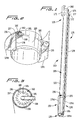
- minimally invasive instrument 100 has a covering apparatus 132 coupled thereto.
- the covering apparatus 132 includes an elongated cylindrical tube or sleeve (sheath) 105, which includes a proximal end 125, a distal end 130, and an outer surface 120.
- a viewing instrument 260 is receivable within the sheath 105. It should be appreciated that although sleeve 105 in Fig. 1 extends the length of the viewing instrument 260, the sleeve alternatively can extend only over a distal portion of the viewing instrument 260.
- the viewing instrument 260 includes a viewing portion or lens 265 at a distal end. During the course of a surgical procedure, the lens 265 is susceptible to obstruction by debris and/or moisture which may distort and/or obstruct viewing through the lens 265.
- the covering apparatus 132 includes a length of tape or film 135 5 that extends along both sides of the surgical viewing instrument and over the viewing portion 265 thereof
- the length of tape 135 begins at a first tube 177 at a proximal end of the sleeve 105 and extends along the length of the sleeve 105, over guide tube 155 which spaces the tape 135 from sleeve 105, around the viewing portion 265 and proximally to second tube 156.
- a clean portion of the tape 135 is advanced from the first tube 177 and a dirty portion of the tape 135 is advanced and received within a second tube 156 after it passes by lens 265.
- tape portion 135v overlies the lens 265, a clean portion 135c is on one side of the sleeve 105 and instrument 260 and portion 135d is on the other side. Portion 135v can be moved away from the lens 265 and portion 135d will be taken up within tube 156.
- a roller 172 is positioned within tube 177 and a roller 157 is positioned within tube 156.
- a length of tape is wound about each roller.
- the roller 172 in tube 177 can be actuated to move the tape 135 in the other direction, i.e. to wind about the roller 172 in tube 177 and unwind from the roller 157 in tube 156.
- the roller 172 instead of roller 157 is the take up roller and the roller 157 instead of roller 172 is the supply roller.
- Such advancement of tape 135 can be performed during the procedure to continue removing dirty portions of the tape 135 from the viewing portion 265 and replacing it with cleaner portions of the tape.
- the dirty portions of the tape moved past the viewing portion 265 are wound about roller 157.
- Various methods can be used to wind roller 157.
- a wire or cable extends from the roller 157 and is actuated by a rotating lever to rotate the roller 157.
- a pulley system is provided, such as pulley system 176.
- the roller 172 within tube 177 can be used to advance the tape 135 in a reverse direction than that described above.
- handle 171 can be operably connected to the roller 172 within proximal tube 177 such that rotation of the handle 171 rotates the roller 172 to advance the tape from within tube 156 (unrolled from roller 157) and wind it about the roller 172 in tube 177.
- the portion 135d of tape 135 would be moved across the lens 265 after portion 135v is removed.
- each roller 157, 172 includes the length of tape 135 wound thereabout to form a spool of tape.
- Tube 156 includes a slot 160 through which one end of the tape 135 extends into to engage the roller 157; tube 177 includes a similar slot 174 through which the other end of the tape 135 extends.
- Support arms 181, 182 extend from roller 157 and from guide 155, respectively, and are fixedly positioned therein to frictionally engage a band or collar 183 which is frictionally secured over the outer surface of the sleeve 105 to thereby secure the tubes 156 and 155 (and roller 157).
- the arm 181 can alternatively be coupled to the tube 156 to frictionally secure the tube to the band 183.
- a similar arm (not shown) can be used to frictionally secure tube 177 and roller 172.
- roller 157 is rotated clockwise to translate the tape 135 from roller 172 to remove a dirty portion of the tape 135 from the lens.
- clean tape portion 135c is shown along one side of the viewing instrument 260 and portion 135d of tape 135 is on the other side.
- the rollers 157, 172 have already been rotated to remove the dirty portion of the tape 135. More specifically, Figure 4 shows portion 135v translated proximally past the lens 265 with a different viewing portion 135c positioned over the viewing portion 265 of the viewing instrument 260. (Portion 135d has been wound about roller 157 and is now within tube 156). A clean portion of tape 135 is designated by reference numeral 135e.
- roller 157 is again rotated to advance the tape 135 so that viewing portion 135c is removed from the lens 260 and a new clean viewing portion 135e is positioned over the lens 265 as shown in Figure 5 .
- a clean portion 135f awaits advancement over the viewing portion 265 should portion 135e be covered with too much debris.
- the rollers 157, 172 can be rotated as desired to continue to advance clean portions of the tape 135 over the viewing portion 265 of viewing instrument 260.
- roller 172 can be rotated to wind the tape 135 about roller 172, thereby moving the tape 135 in the opposite direction from that shown in Figures 4 and 5 .
- the ratchet wheel 165 is connected to the roller 157.
- the pawl 168 is adapted to fit between the teeth 166 to permit rotation of the roller 157 in a first direction and to inhibit rotation of the roller 157 in a second direction.
- the pawl 168 is in a hinged relationship with arm 181 that is secured to roller 157. It should be appreciated, in alternate embodiments, the ratchet mechanism can be operably coupled to the roller 172.
- the positioning of the tape 135 adjacent the viewing portion 265 may form a substantially sealed relationship between the viewing portion 265 and the tape 135.
- a sealed relationship between the viewing portion 265 and the tape 135 inhibits the depositing and the accumulation of contaminants, e.g. , debris and/or moisture, on the viewing portion 265 of the viewing instrument 260.
- cylindrical tube or sleeve (sheath) 205 has a pair of curved distal extensions 207, 209 forming guides for the tape 235.
- the covering apparatus of Figure 1A is identical to the apparatus of Figure 1 , e.g. , it contains a roller within tube 210, a guide 211 and a proximal roller within a proximal tube, all identical to respective rollers 157, 172 within tubes 156, 177 and guide 155.
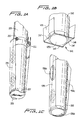
- the tape 335 provides a tighter fit as the tape 335 is wound adjacent the outer surface of the cylindrical tube or sleeve (sheath) 310 positioned over the viewing instrument 260. More specifically, in this embodiment, tube 312 houses a roller 313 and tube 314 houses a roller 315. Both tubes 312, 314 are positioned at the proximal end of the apparatus. Support arms 306, 308 mount the tubes 312, 314 to the outer surface of the sleeve 310 (or directly to the outer surface of the viewing instrument 260 if a sleeve is not utilized) in the same manner as arms 181, 182 of Figure 2 .
- a ratchet mechanism 320 similar to the ratchet mechanism 162 of Figures 2 and 3 can be provided to limit roller rotation in one direction.
- the ratchet 320 is provided to operatively engage roller 315 but can alternately operatively engage roller 313 within tube 312 to limit rolling, and therefore movement of the tape 335, in one direction. Since the tape 335 winds around the inner side of the tubes and rollers, the tape 335 can be fit tighter around the viewing instrument and therefore tighter around the viewing portion 265. Note in the illustration of Figure 6 , two dirty portions 335v and 335e of tape 335 have already been moved from the viewing portion 265 to enable a clean portion 335f to be placed over the viewing portion (lens) 265.
- roller within tube 414 could be the supply roller and the roller within tube 412 the take up roller.
- Arms 430, 432 support the tubes 412, 414 and rollers in the same manner as arms 181, 182 of Figure 2 . Note that a dirty portion 435d has been moved away from the viewing portion 265 and a cleaner portion 435g of the tape 435 overlies the viewing portion 265.
- tubes 452, 454 are connected by a ring 460 which encircles and frictionally engages the cylindrical tube or sleeve (sheath) 450, or encircles to frictionally engage the viewing instrument if the ring 460 is mounted directly to the viewing instrument in embodiments not utilizing a sleeve.
- Ring 460 extends through the roller 456 which is rotatably positioned within tube 454 and through the ratchet wheel 457 of ratchet 459 and the roller rotatably mounted within tube 452.
- Ratchet 459 limits movement of the rollers, and thus the tape 465, to movement in one direction as in the aforedescribed ratchets.
- the rollers can be rotated to advance the tape in the same manner as the rollers described above.
- the positioning of the tape 135 (and other tapes/films described herein) against the surface of the viewing portion 265 generally inhibits the depositing of debris and/or moisture on the surface of the viewing portion, debris and/or moisture may nonetheless cover the viewing portion and therefore it would be desirable to provide a covering apparatus in the form of a cleaning apparatus having a tape 135 that will clean the surface of the viewing portion 265.
- a portion or an entire length of the tape may be impregnated with various materials and/or substances to facilitate cleaning of the viewing portion 265. These materials and/or substances may alter the opacity of the tape.
- the portion of the tape 135 abutting the viewing portion 265 will facilitate an unaltered and unobstructed view of the surgical site.
- the tape 135 may be impregnated with, or otherwise include, cleaning materials and/or substances in an alternating pattern to facilitate cleaning while still permitting advancing the tape 135 to have a substantially clean transparent portion of the tape 135 abutting the viewing portion 265.
- the cleaning materials and/or substances may include materials and/or substances that absorb moisture and/or condensation.
- the tape 535 may include multiple cut-out portions such as cutout portions 536a, 536b and 536b.
- Tape 535 is advanced to clean the viewing portion 265 of the viewing instrument as the solid (non-cutout) portions of tape 535 move across and in contact with the viewing portion 265, and can contain cleaning materials or substances as described above.
- the tape 535 is advanced until a second cutout portion, e.g. , cutout 536b, is positioned over the viewing portion 265 to provide an unobstructed view. If the viewing portion 265 becomes covered with debris, the tape 535 can be further advanced in the manner described above with respect to the other tapes, e.g. , with the use of rotatable rollers, to have a solid portion wipe the lens and position the cut-out portion 536c of the tape 535 over the viewing portion 265. Additional cutouts can be provided to provide for subsequent advancement of the tape.
- the covering apparatus may be coupled to the outer surface of the cylindrical tube or sleeve (sheath) by a C-shaped clip which frictionally engages the sleeve or viewing instrument if mounted directly to the viewing instrument.
- the clip is biased to apply a compressive force about the sleeve to secure the rollers to the sleeve.
- the C-shaped clip may secure the rollers directly to the viewing instrument 260.
- the covering apparatus may be permanently or removably coupled to either the sleeve or to the viewing instrument.
- the covering apparatus may be operably and removably coupled to existing surgical instruments.
- a covering apparatus 350 includes a tape in the form of a film 355, having transparent sections or formed entirely of a transparent material.
- the film includes holes 360 along its length.
- a flexible wire can be provided to interweave through the holes 360 along the length of the film 355.
- the holes 360 and flexible wire can also be an alternative way to hold and advance the tape 135 of Figure 1 .
- a roller 362 and 364 for each end of the film 355 can include an opening to hold and engage each end of the flexible wire.
- a ratchet mechanism 370 similar to ratchet mechanism 162, is provided on one of the rollers, e.g.
- the dirty take up roller instead of driving the dirty take up roller at the end of the shaft by the pulley mechanism, the dirty take up roller can be positioned closer to the user's hand so it can be moved, i.e., wound, directly by the user. This simplifies the device.
- a power supply can also be utilized in alternate embodiments to rotate the roller to advance the tape.
Landscapes
- Health & Medical Sciences (AREA)
- Life Sciences & Earth Sciences (AREA)
- Surgery (AREA)
- Public Health (AREA)
- Biomedical Technology (AREA)
- Heart & Thoracic Surgery (AREA)
- Medical Informatics (AREA)
- Molecular Biology (AREA)
- Animal Behavior & Ethology (AREA)
- General Health & Medical Sciences (AREA)
- Engineering & Computer Science (AREA)
- Veterinary Medicine (AREA)
- Physics & Mathematics (AREA)
- Biophysics (AREA)
- Nuclear Medicine, Radiotherapy & Molecular Imaging (AREA)
- Optics & Photonics (AREA)
- Pathology (AREA)
- Radiology & Medical Imaging (AREA)
- Surgical Instruments (AREA)
- Endoscopes (AREA)
Applications Claiming Priority (2)
| Application Number | Priority Date | Filing Date | Title |
|---|---|---|---|
| US201161440991P | 2011-02-09 | 2011-02-09 | |
| US13/361,194 US20120238818A1 (en) | 2011-02-09 | 2012-01-30 | Covering Apparatus For An Endoscope Lens |
Publications (2)
| Publication Number | Publication Date |
|---|---|
| EP2486845A2 true EP2486845A2 (de) | 2012-08-15 |
| EP2486845A3 EP2486845A3 (de) | 2012-11-07 |
Family
ID=45655425
Family Applications (1)
| Application Number | Title | Priority Date | Filing Date |
|---|---|---|---|
| EP12154377A Withdrawn EP2486845A3 (de) | 2011-02-09 | 2012-02-08 | Abdeckvorrichtung für eine Endoskoplinse |
Country Status (3)
| Country | Link |
|---|---|
| US (1) | US20120238818A1 (de) |
| EP (1) | EP2486845A3 (de) |
| CA (1) | CA2766671A1 (de) |
Cited By (4)
| Publication number | Priority date | Publication date | Assignee | Title |
|---|---|---|---|---|
| FR2995776A1 (fr) * | 2012-09-26 | 2014-03-28 | Sofradim Production | Membrane hydrophobe pour lentille |
| WO2015140065A1 (en) * | 2014-03-17 | 2015-09-24 | X-Med S.R.L. | Protection device for diagnostic instruments of the optical type and corresponding method of manufacture |
| CN106061351A (zh) * | 2013-12-20 | 2016-10-26 | 益安生医股份有限公司 | 透镜盖改型 |
| US10307041B2 (en) | 2007-06-08 | 2019-06-04 | Medeon Biodesign, Inc. | Lens cover modification |
Families Citing this family (13)
| Publication number | Priority date | Publication date | Assignee | Title |
|---|---|---|---|---|
| US9700378B2 (en) | 2013-04-26 | 2017-07-11 | Medtronic Xomed, Inc. | Endoscope lens cleaning device |
| DE102014202075B4 (de) | 2014-02-05 | 2018-03-01 | Deutsches Zentrum für Luft- und Raumfahrt e.V. | Kamerasystem sowie Verfahren zur Reinigung einer Kamera |
| ES2718558T3 (es) | 2014-05-06 | 2019-07-02 | Buffalo Filter Llc | Limpieza de laparoscopio y endoscopio y dispositivo para desempañar |
| US10709321B2 (en) | 2016-07-13 | 2020-07-14 | Washington University | Self-cleaning endoscope |
| JP6865410B2 (ja) * | 2016-10-06 | 2021-04-28 | デクセリアルズ株式会社 | 視野確保装置、及び内視鏡システム |
| CA3120320C (en) * | 2018-11-29 | 2022-12-06 | Board Of Regents, The University Of Texas System | Devices, systems and methods for cleaning of elongated instrument surface |
| US11575807B2 (en) * | 2020-01-20 | 2023-02-07 | Monomer Software LLC | Optical device field of view cleaning apparatus |
| US11013399B1 (en) * | 2020-01-27 | 2021-05-25 | Board Of Regents, The University Of Texas System | Wiper assembly for imaging element cleaning apparatus |
| CN112401825A (zh) * | 2020-11-27 | 2021-02-26 | 瑞惜康(苏州)医疗科技有限公司 | 一种防止镜头污染雾化的腹腔镜 |
| US20220304563A1 (en) * | 2021-03-26 | 2022-09-29 | Vicarious Surgical Inc. | Lens cleaning system and method for a surgical camera |
| US12004724B2 (en) | 2021-05-06 | 2024-06-11 | Medtronic Xomed, Inc. | Endoscope cleaning system |
| CN113384222B (zh) * | 2021-05-18 | 2022-09-06 | 李标 | 一种带有冲洗功能的胸腔镜镜头装置 |
| US12235387B2 (en) * | 2022-03-11 | 2025-02-25 | International Truck Intellectual Property Company, Llc | Sensor shield and method |
Family Cites Families (4)
| Publication number | Priority date | Publication date | Assignee | Title |
|---|---|---|---|---|
| JP2005052229A (ja) * | 2003-08-07 | 2005-03-03 | Olympus Corp | 視野確保装置 |
| JP4756986B2 (ja) * | 2005-10-14 | 2011-08-24 | オリンパスメディカルシステムズ株式会社 | 内視鏡用シース、内視鏡装置 |
| WO2008153841A2 (en) * | 2007-06-08 | 2008-12-18 | Thomas Hsu | Devices and methods for removal of debris from the objective lens of an endoscope |
| DE102008059633A1 (de) * | 2008-11-28 | 2010-06-02 | Aesculap Ag | Endoskop für medizinische Zwecke |
-
2012
- 2012-01-30 US US13/361,194 patent/US20120238818A1/en not_active Abandoned
- 2012-02-02 CA CA2766671A patent/CA2766671A1/en not_active Abandoned
- 2012-02-08 EP EP12154377A patent/EP2486845A3/de not_active Withdrawn
Non-Patent Citations (1)
| Title |
|---|
| None |
Cited By (7)
| Publication number | Priority date | Publication date | Assignee | Title |
|---|---|---|---|---|
| US10307041B2 (en) | 2007-06-08 | 2019-06-04 | Medeon Biodesign, Inc. | Lens cover modification |
| US10986982B2 (en) | 2007-06-08 | 2021-04-27 | Medeon Biodesign, Inc. | Lens cover modification |
| FR2995776A1 (fr) * | 2012-09-26 | 2014-03-28 | Sofradim Production | Membrane hydrophobe pour lentille |
| WO2014048972A1 (en) * | 2012-09-26 | 2014-04-03 | Sofradim Production | Hydrophobic membrane for a lens and method of protecting a lens with such a membrane |
| CN106061351A (zh) * | 2013-12-20 | 2016-10-26 | 益安生医股份有限公司 | 透镜盖改型 |
| CN106061351B (zh) * | 2013-12-20 | 2019-04-12 | 益安生医股份有限公司 | 透镜盖改型 |
| WO2015140065A1 (en) * | 2014-03-17 | 2015-09-24 | X-Med S.R.L. | Protection device for diagnostic instruments of the optical type and corresponding method of manufacture |
Also Published As
| Publication number | Publication date |
|---|---|
| CA2766671A1 (en) | 2012-08-09 |
| EP2486845A3 (de) | 2012-11-07 |
| US20120238818A1 (en) | 2012-09-20 |
Similar Documents
| Publication | Publication Date | Title |
|---|---|---|
| EP2486845A2 (de) | Abdeckvorrichtung für eine Endoskoplinse | |
| US10986982B2 (en) | Lens cover modification | |
| US10335021B2 (en) | Endoscope wiper blade cleaner | |
| US8979738B2 (en) | Devices and methods for removal of debris from the objective lens of an endoscope | |
| US9241610B2 (en) | Devices and methods for removal of debris from the objective lens of an endoscope | |
| US20130150670A1 (en) | Thoracic scope port cleaner | |
| US20120108904A1 (en) | Cleaner for endoscope | |
| EP3082562B1 (de) | Modifikation einer objektivschutzkappe | |
| CA2546876A1 (en) | Medical devices for use with endoscope | |
| CN221512181U (zh) | 一种能够提高内窥镜或腔镜可视性的透镜防护套 | |
| WO2010067762A1 (ja) | 観察装置と内視鏡装置 | |
| JP3190560B2 (ja) | 湾曲部保護機構を備えた内視鏡 | |
| CN118592876A (zh) | 一种器械收放机构及内窥镜 |
Legal Events
| Date | Code | Title | Description |
|---|---|---|---|
| PUAI | Public reference made under article 153(3) epc to a published international application that has entered the european phase |
Free format text: ORIGINAL CODE: 0009012 |
|
| AK | Designated contracting states |
Kind code of ref document: A2 Designated state(s): AL AT BE BG CH CY CZ DE DK EE ES FI FR GB GR HR HU IE IS IT LI LT LU LV MC MK MT NL NO PL PT RO RS SE SI SK SM TR |
|
| AX | Request for extension of the european patent |
Extension state: BA ME |
|
| PUAL | Search report despatched |
Free format text: ORIGINAL CODE: 0009013 |
|
| AK | Designated contracting states |
Kind code of ref document: A3 Designated state(s): AL AT BE BG CH CY CZ DE DK EE ES FI FR GB GR HR HU IE IS IT LI LT LU LV MC MK MT NL NO PL PT RO RS SE SI SK SM TR |
|
| AX | Request for extension of the european patent |
Extension state: BA ME |
|
| RIC1 | Information provided on ipc code assigned before grant |
Ipc: A61B 1/00 20060101AFI20121004BHEP Ipc: A61B 1/12 20060101ALI20121004BHEP |
|
| RAP1 | Party data changed (applicant data changed or rights of an application transferred) |
Owner name: COVIDIEN LP |
|
| 17P | Request for examination filed |
Effective date: 20130107 |
|
| STAA | Information on the status of an ep patent application or granted ep patent |
Free format text: STATUS: THE APPLICATION HAS BEEN WITHDRAWN |
|
| 18W | Application withdrawn |
Effective date: 20140313 |