EP2486798A2 - Changeable insert for a rotating nozzle - Google Patents
Changeable insert for a rotating nozzle Download PDFInfo
- Publication number
- EP2486798A2 EP2486798A2 EP12150860A EP12150860A EP2486798A2 EP 2486798 A2 EP2486798 A2 EP 2486798A2 EP 12150860 A EP12150860 A EP 12150860A EP 12150860 A EP12150860 A EP 12150860A EP 2486798 A2 EP2486798 A2 EP 2486798A2
- Authority
- EP
- European Patent Office
- Prior art keywords
- dough
- insert
- rotation
- axis
- interchangeable insert
- Prior art date
- Legal status (The legal status is an assumption and is not a legal conclusion. Google has not performed a legal analysis and makes no representation as to the accuracy of the status listed.)
- Granted
Links
- 238000003825 pressing Methods 0.000 claims abstract description 35
- 235000014594 pastries Nutrition 0.000 claims abstract description 9
- 238000007906 compression Methods 0.000 claims abstract description 5
- 238000003860 storage Methods 0.000 claims description 6
- 230000006835 compression Effects 0.000 claims description 4
- 238000004891 communication Methods 0.000 claims description 3
- 229920001343 polytetrafluoroethylene Polymers 0.000 claims description 3
- 239000004810 polytetrafluoroethylene Substances 0.000 claims description 3
- 229910001220 stainless steel Inorganic materials 0.000 claims description 3
- 239000010935 stainless steel Substances 0.000 claims description 3
- 239000002184 metal Substances 0.000 claims description 2
- 239000004033 plastic Substances 0.000 claims description 2
- 229920003023 plastic Polymers 0.000 claims description 2
- -1 polytetrafluoroethylene Polymers 0.000 claims description 2
- 238000007599 discharging Methods 0.000 abstract 1
- 230000008859 change Effects 0.000 description 13
- 235000015895 biscuits Nutrition 0.000 description 11
- 238000004519 manufacturing process Methods 0.000 description 10
- 238000004140 cleaning Methods 0.000 description 5
- 238000000034 method Methods 0.000 description 4
- 230000008569 process Effects 0.000 description 3
- 238000005520 cutting process Methods 0.000 description 2
- 235000013305 food Nutrition 0.000 description 2
- 238000003780 insertion Methods 0.000 description 2
- 230000037431 insertion Effects 0.000 description 2
- 238000003892 spreading Methods 0.000 description 2
- 230000007480 spreading Effects 0.000 description 2
- 239000004809 Teflon Substances 0.000 description 1
- 229920006362 Teflon® Polymers 0.000 description 1
- 238000006243 chemical reaction Methods 0.000 description 1
- 238000001816 cooling Methods 0.000 description 1
- 230000008878 coupling Effects 0.000 description 1
- 238000010168 coupling process Methods 0.000 description 1
- 238000005859 coupling reaction Methods 0.000 description 1
- 230000001419 dependent effect Effects 0.000 description 1
- 238000013461 design Methods 0.000 description 1
- 238000001125 extrusion Methods 0.000 description 1
- 238000012423 maintenance Methods 0.000 description 1
- 239000000463 material Substances 0.000 description 1
- 238000004806 packaging method and process Methods 0.000 description 1
- 230000002093 peripheral effect Effects 0.000 description 1
- 235000012434 pretzels Nutrition 0.000 description 1
- 238000012545 processing Methods 0.000 description 1
- 230000003716 rejuvenation Effects 0.000 description 1
- 238000005096 rolling process Methods 0.000 description 1
- 238000007789 sealing Methods 0.000 description 1
- 238000012546 transfer Methods 0.000 description 1
Images


Classifications
-
- A—HUMAN NECESSITIES
- A21—BAKING; EDIBLE DOUGHS
- A21C—MACHINES OR EQUIPMENT FOR MAKING OR PROCESSING DOUGHS; HANDLING BAKED ARTICLES MADE FROM DOUGH
- A21C11/00—Other machines for forming the dough into its final shape before cooking or baking
- A21C11/16—Extruding machines
Definitions
- Rotary nozzles are used in pressing devices for the production of biscuit sticks such as classic pretzel sticks.
- Such a pressing device with a rotary nozzle is in the EP 1 779 732 A2 disclosed.
- Such pressing devices have a plurality of juxtaposed rotary nozzles, so that at the same time a plurality of dough strands can be pressed, which are then further processed into biscuit bars.
- the rotary nozzles are pre-mounted on a nozzle carrier and integrated in the pressing device.
- a product change ie a change in the dough product to be produced, the corresponding rotary nozzles must be replaced.
- Such a conversion process for an intended product change is time-consuming and thus costly.
- a changeover insert according to the invention for a rotary nozzle makes it possible, in the case of a planned product change on a pressing device, to have the rotary nozzle installed in the pressing device, in particular in a nozzle carrier provided therefor.
- the interchangeable insert In order to carry out the product change it is possible by using the interchangeable insert that only the interchangeable insert in the rotary nozzle is to be exchanged. This is one planned product change less complicated and therefore faster and cheaper to carry out.
- a disassembly of the changeover insert from the rotary nozzle is less complicated than a disassembly of the rotary nozzle from the nozzle carrier.
- the rotary nozzles are arranged rotatably drivable in the pressing device via a gearbox.
- the rotatably driven arrangement in the pressing device of the rotary nozzles requires a cooperation of various mechanical components.
- the changeover insert is held exclusively in the rotary nozzle itself.
- a coupling with several other components that would have to be decoupled for disassembly of the interchangeable insert is not provided in the interchangeable insert.
- the replacement insert simplifies a cleaning process of the nozzles in the event of a possible product change. For cleaning, the removable insert can be removed from the rotary nozzle and cleaned.
- the rotary nozzle itself can dwell in the nozzle carrier during the cleaning of the changeover insert in the pressing device.
- the exchange insert has an axis of rotation, a feed opening for feeding dough and at least one discharge opening for dispensing the dough. Furthermore, the feed opening and the at least one discharge opening are connected by a dough guide channel so that dough can be conveyed from the feed opening along a dough guide direction through the dough guide channel to the at least one discharge opening during production of biscuit bars.
- the dough pressed by the interchangeable insert is additionally compacted.
- biscuit bars can be made, which are wound around each other in the form of a helix and in particular in the form of a multiple helix.
- An interchangeable insert according to claim 6 allows an inexpensive, uncomplicated and secure attachment of the interchangeable insert in a rotary nozzle. As a result of such attachment, the interchangeable insert is held both axially along the axis of rotation and tangentially against rotation about the axis of rotation in the rotary nozzle.
- a removable insert according to claim 7 allows a conical surface in a mounting portion both the axial securing and securing against rotation. With such a mounting portion several security functions are met at the exchange insert. Such attachment of the exchange insert is effective.
- An interchangeable insert according to claim 8 is designed for production and allows a production of the insert of different materials and by means of different methods.
- a changeover insert has a substantially constant along the axis of rotation and homogeneous stability and strength.
- a wall thickness of a wall of the exchange insert has, with respect to the wall thickness at a feed opening, ie following a possibly provided insertion bevel, a deviation of at most 30%, in particular of at most 20% and in particular of at most 10%.
- At a discharge opening of the exchange insert may occur depending on a selected cross-sectional geometry of the discharge opening a greater deviation of the wall thickness.
- An interchangeable insert with the possible cross-sectional shapes of the at least one dispensing opening specified in claim 9 allows a variety in the design of various dough products.
- the shape of the cross section of the at least one discharge opening can be carried out in accordance with a product to be produced.
- other than the mentioned cross-sectional shapes are conceivable.
- a change insert according to claim 10 is robust, suitable for food and inexpensive to produce.
- An exchange insert according to claim 11 is designed particularly robust. Due to the fact that the interchangeable insert is designed substantially sleeve-shaped, it has a stable and rigid structure. The interchangeable insert withstands an internal pressure which occurs in particular due to the pushing of the dough through the rotary nozzle or through the interchangeable insert. The changeover insert is in particular more stable than a sheet-formed perforated plate.
- a rotating nozzle with a removable insert receptacle which is provided for receiving a removable insert
- the use of a removable insert is made possible on the rotary nozzle.
- Such a rotary nozzle with a replacement insert used can be retrofitted quickly and inexpensively by replacing the replacement insert.
- the cleaning of the rotary nozzle is not required. It is sufficient to clean the removable insert.
- the rotary nozzle may remain mounted on the rotary nozzle carrier in the pressing device for a longer period, in particular during the entire life of the rotary nozzle.
- the rotary nozzle can be used universally, i. With the same rotating nozzle different pastry strands can be produced by using different interchangeable inserts. As a result, the number of required supply of rotating nozzles at a food manufacturer is reduced.
- the rotary nozzles with the exchange insert receiving have a simplified geometry compared to a conventional rotary nozzle with an optionally elaborately designed discharge-side nozzle opening and are therefore less expensive, faster and cheaper to produce.
- FIG. 1 schematically illustrated pressing device 1 is part of an otherwise not shown plant for the production of pastry bars.
- a feed hopper is placed, which is not shown in the drawing, and is fed via the dough of a storage chamber 3.
- a direct manual feed into the storage chamber 3 can also be effected.
- a corrugating roller 4 is arranged in Fig. 1 is shown schematically and in particular without corrugation. From the perspective Fig. 1 Seen the corrugating roller 4 rotates clockwise. In a peripheral area, the in Fig. 1 corresponds approximately to an upper right quadrant, the corrugating roller 4 is connected to the dough in the storage chamber 3 in conveying connection.
- the storage chamber 3 tapers, in Fig. 1 bounded to the left of the corrugating roll 4 and to the right of a pressure-stable wall 5, down.
- About a bottleneck 6 at the site of the strongest rejuvenation is the pantry 3 with a dough-pressure chamber 7 in combination, located in the Fig. 1 and 3 extends from the corrugating roller 4 from the bottom right.
- the corrugating roller 4 continues to be in conveying contact with the dough. Downstream, a stationary scraper blade 8 which is adjacent to the corrugating roller 4 with minimum clearance limits the dough pressure chamber 7.
- the rotary nozzle 9 On the delivery side is the dough pressure chamber 7 with a in the Fig. 1 and 3 illustrated rotary nozzle 9 for pressing a pastry strand 10 in conjunction.
- the rotary nozzle 9 has a rotary head 11 which is driven to rotate about a rotation axis 12.
- the axis of rotation 12 coincides with a rotational symmetry axis of the rotary head 11.
- An inner space 13 of the rotary nozzle 9 communicating with the dough pressure chamber 7 tapers conically toward a discharge-side nozzle opening 14. The latter is arranged concentrically to the axis of rotation 12.
- the rotary head 11 is designed as a rotary insert in a nozzle carrier 15. Via an input-side first sliding bearing 17 and a nozzle-side 14 surrounding the discharge-side second sliding bearing 18 of the rotary head 11 is axially and radially mounted in the nozzle carrier 15.
- the plain bearings 17, 18 are designed as sliding sleeves.
- the rotary head 11 may be mounted in the nozzle carrier 16 by means of rolling bearings.
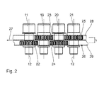
- the side view of Fig. 2 shows next to the turret 11 even more turrets 19 to 21 of these nozzles.
- more than four turrets are usually provided.
- up to 40 or more turrets can be used on a working width perpendicular to the drawing plane FIGS. 1 and 3 be provided between 800 mm and 1400 mm.
- the turrets 11 and 19 to 21 are all driven to rotate about mutually parallel axes of rotation, which are all designated in the drawing by the reference numeral 12.
- Two adjacent axes of rotation are arranged at a distance of 25 mm from each other.
- all rotary heads are arranged at the same distance from each other along the working width.
- a rotary drive for the turrets 11 and 19 to 21 has a drive train about pinion 22 to 25 of each rotary head 11, 19 to 21 running and designed as a belt 26 and metallic tooth chain endless traction member.
- the belt 26 is perpendicular to its path 27 and parallel to the plane of the Fig. 2 divided into two tensile sections 28, 29, wherein the tensile portion 28 of the input side of the rotary heads 11, 19 to 21 and the pulling portion 29 of the discharge side of the rotary heads 11, 19 to 21 faces.
- the drive pinion 22 to 25 adjacent rotary heads 11, 19 to 21 are offset in height by a distance h to each other. In a first turret group with the turrets 11 and 20 are therefore the drive pinion 22, 24 in Fig.
- the offset h corresponds to the distance between the two tensile sections 28, 29 of the belt 26 to each other.
- the pulling section 29 passes over the driving pinions 22, 24 of the rotary heads 11, 20 of the first turret group.
- the pulling section 28 passes over the drive pinions 23, 25 of the rotary heads 19, 21 of the second rotary head group. Therefore, the pulling portion 29 of the belt 26 for driving the first turret group and the second pulling portion 28 for driving the second turret group are formed.
- the two tension sections 28, 29 are arranged on an inner side of the belt 26. On the outside, the pull sections 28, 29 are supported by two slide rails 30, 31 against the nozzle carrier 15. The two tension sections 28, 29 are separated from each other by a guide web 32.
- the dough is squeezed out through the rotary nozzles 9.
- the rotary heads 11, 19 to 21, driven by the belt 26 and a motor, not shown, are rotated. This rotation causes the biscuit strand 10, which is pressed out of the nozzle opening 14, to be twisted after the rotary heads 11, 19 to 21 in the form of a helix.
- the latter is further transported by a driven endless conveyor belt 37 for baking.
- the plant for the production of biscuits still on a cooling and packaging device.
- the plant may also comprise a lye bath, a spreading unit with a spreading conveyor and a cutting unit with a cutting and oven transfer conveyor.
- All rotary nozzles 9 are in communication with the dough pressure chamber 7. Depending on the number of rotary nozzles 9, a corresponding number of pastry strands 10 can be pressed out at the same time with the pressing device 1 and conveyed on to the endless conveyor belt 37.
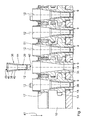
- Fig. 4 shows a front view of the pressing device 1 with a gear box 16 and the nozzle carrier 15.
- rotary nozzles 9 are provided rotatably drivable.
- Such a nozzle carrier 15 has a useful width of 1150 mm. It is also possible to equip the nozzle carrier 15 with 31 rotary nozzles 9, 39 rotary nozzles 9 or 55 rotary nozzles 9.
- the nozzle carrier 15 then has a useful width of 750 mm, 950 mm and 1350 mm respectively.
- the effective width of the nozzle carrier 15 results from the intermediate spaces arranged between the rotary nozzles 9 and the width of the intermediate spaces, which according to the exemplary embodiment shown constant at 25 mm. It is conceivable to provide other than the rotary nozzle numbers mentioned on a nozzle carrier 15.
- Fig. 5 shows the pressing device 1 according to Fig. 4 , wherein the nozzle carrier 15 is removed from the gear box 16.
- the gearbox 16 together with the nozzle carrier 15 of the pressing device 1, which is designed as embroidery press, to a parallel to the axis of rotation of the Riffelwalze 4 arranged pivot axis 52 pivots. It is not necessary to disassemble the gear box 16 from the nozzle carrier 15 to allow accessibility of the interchangeable inserts 36.
- the interchangeable inserts 36 can be replaced. This simplifies the accessibility of the interchangeable inserts.
- FIG. 6 shows the pressing device 1 with the pivotable about a pivot axis 52 pivotally mounted nozzle carrier 15, is mounted on the gear box 16.
- the nozzle carrier 15 is shown in a pivoted arrangement. In this arrangement, it is possible to remove the interchangeable inserts 36 from the gear box 16. Starting from this maintenance and exchange arrangement of the nozzle carrier 15, this can be pivoted along a pivoting direction 53 about the pivot axis 52 into a working arrangement. The pivoting movement takes place in the pivoting direction 53 with respect to the pivot axis by approximately 90 °.
- the nozzle carrier 15 is substantially vertical as shown in FIG Fig. 1 arranged.
- the dough pressure chamber 7 is then connected to the storage chamber 3.
- Fig. 7 shows an enlarged sectional view of the gear box 16 with a plurality of rotatable about its respective axis of rotation 12 arranged rotary nozzles 9.
- an external toothing 51 adjacent rotary nozzles 9 is arranged offset.
- the staggered arrangement of the rotary nozzles 9 is carried out such that in each case the next but one rotary nozzle 9 is made identical.
- the staggered arrangement of the rotary nozzles 9 thus takes place alternately.
- Such an arrangement of the rotary nozzles 9 is compact and serves the drive for the tensile strand.
- the nozzles 9 have identical inner contours and have an exchange insert receptacle 35, which is arranged in the region of the nozzle opening 14 within the rotary nozzle 9.
- the exchange insert receptacle 35 has a conically executed inner contour.
- the exchange insert 36 is inserted along the axis of rotation 12.
- the exchange insert 36 has a fastening section 38 with a conical surface on an outer contour.
- the outer contour of the interchangeable insert 36 surrounds a dough guide channel 39 which connects a feed opening 40 along a dough guide direction 41 to a dispensing opening 42.
- the feed opening 40 serves to feed dough into the exchange insert 36.
- the discharge opening 42 serves to dispense the dough pressed by the exchange insert 36.
- the nozzle opening 14 and the discharge opening 42 are arranged adjacent to each other and in particular concentrically with the axis of rotation 12.
- the exchange insert 36 is designed substantially sleeve-shaped and can be inserted as a plug-in sleeve into the rotary nozzle 9.
- the interchangeable insert 36 Perpendicular to the axis of rotation 12, the interchangeable insert 36 has a substantially annular cross-sectional area, wherein the inner contour of the cross-sectional area, in particular in the area of the dispensing opening 42, is non-circular can be. In the region of the dispensing opening 42, the cross-sectional area of the interchangeable insert 36 is dependent on a product to be produced. Along the axis of rotation 12, the cross-sectional area may be variable, ie size and / or shape of outer and / or inner contour.
- the interchangeable insert 36 is securely held by the mounting portion 38 in the removable insert holder 35 of the rotary nozzle 9. Due to the conical surface of the attachment portion 38, the exchange insert 36 is axial, i. along the dough guide direction 41, securely held in the rotary nozzle 9. An axial slippage due to a pressing force is thereby prevented. In addition, the interchangeable insert 36 is secured against rotation about the axis of rotation 12 by the frictional force acting in the region of the fastening section 38 between the interchangeable insert 36 and the interchangeable insert holder 35 of the rotary nozzle 9. The interchangeable insert 36 has along the axis of rotation 12 a substantially constant wall thickness of a wall 44.
- the discharge opening 42 has a cross section oriented perpendicular to the axis of rotation 12, which is reduced in relation to a corresponding cross section of the supply opening 40 oriented perpendicular to the axis of rotation 12. Accordingly, a dough pressed by the exchange insert 36 is compressed along the dough-carrying direction 41.
- the dough guide channel 39 is oriented substantially parallel to the axis of rotation 12 and has a compression section 43. In the compression section 43, a cross section of the dough guide channel 39 oriented perpendicular to the axis of rotation 12 is reduced along the dough guide direction 41.
- the exchange insert according to the embodiment shown in the Fig. 7 and 8th has exactly one discharge opening 42. It is also possible that the interchangeable insert 36 has a plurality of dispensing openings 42 in the case of a biscuit strand to be designed correspondingly. In this case, the discharge openings 42 may be arranged concentrically or in another manner with respect to the axis of rotation 12. With multiple dispensing openings, it is possible to make a pastry strand in the form of a multiple helix.
- the feed opening 40 is circular and has an insertion bevel 45.
- the interchangeable insert 36 has a rectangular cross-section oriented perpendicular to the axis of rotation 12.
- the interchangeable insert 36 is made of polytetrafluoroethylene (PTFE), also known under the trade name Teflon. It is also possible to manufacture the interchangeable insert 36 from metal and in particular from stainless steel or other plastics.
- the rotary nozzle 9 is made of stainless steel.
- the rectangular cross-section of the discharge opening 42 is in Fig. 8 shown.
- the rectangular cross section has a ratio of length to width of about 2: 1.
- the ratio can also be greater or less than 2: 1. It is also possible to make the cross section of the discharge opening 42 triangular, pentagonal or in the form of another polygon.
- Fig. 9 shows a further embodiment of the interchangeable insert 36.
- Components that correspond to those already described above with reference to the Fig. 1 to 8 have the same reference numbers and will not be discussed again in detail.
- the cross section of the discharge opening 46 of the exchange insert 36 has a waisted rectangular shape. That is, the discharge port 46 is shaped substantially rectangular, similar to the discharge port 42 of the first embodiment. At the longer, according to Fig. 8 Above and below shown side lines of the discharge opening 46, a radius is provided such that the discharge opening 46 is made concave.
- the discharge opening 46 has a reduced width in a middle region of the longer side lines. In particular, the width of the discharge opening 46 on the axis of rotation 12 is minimal.
- the circular arc sections formed by the radii are arranged opposite to each other.
- the discharge opening 46 is made double symmetrical.
- Fig. 10 shows a further embodiment of a removable insert 36.
- Components that correspond to those already described above with reference to the Fig. 1 to 9 have the same reference numbers and will not be discussed again in detail.
- the exchange insert 36 has a discharge opening 47.
- the discharge opening 47 comprises three at least partially overlapping bores 48, which are arranged parallel to the axis of rotation 12.
- Each of the holes 48 has a diameter of 3 mm.
- the holes 48 are arranged on a circle of holes with the diameter of 3.3 mm at an angular distance of 120 ° with respect to the axis of rotation 12, i. the centers of the holes 48 are arranged on the pitch circle about the rotation axis 12 equidistant. It is also possible to carry out the discharge opening 47 with several or fewer than three bores 48. Accordingly, the diameter of the bolt circle or the diameter of the holes 48 can be varied.
- Fig. 11 shows a further embodiment of the interchangeable insert 36.
- Components that correspond to those already described above with reference to the Fig. 1 to 10 have the same reference numbers and will not be discussed again in detail.
- An exchange insert 36 has a discharge opening 50, which is designed as a circular bore concentric with the axis of rotation 12. Such a discharge opening 50 is uncomplicated and quickly produced.
Landscapes
- Life Sciences & Earth Sciences (AREA)
- Engineering & Computer Science (AREA)
- Food Science & Technology (AREA)
- Manufacturing And Processing Devices For Dough (AREA)
Abstract
Description
Drehdüsen werden in Pressvorrichtungen zur Herstellung von Gebäckstangen wie beispielsweise klassische Salzstangen, sogenannte Sticks, eingesetzt. Eine derartige Pressvorrichtung mit einer Drehdüse ist in der
Es ist daher eine Aufgabe der vorliegenden Erfindung, einen Umrüstvorgang bei einem Produktwechsel für eine Pressvorrichtung zu vereinfachen.It is therefore an object of the present invention to simplify a changeover process in a product change for a pressing device.
Diese Aufgabe ist erfindungsgemäß gelöst durch einen Wechseleinsatz für eine Drehdüse mit den im Anspruch 1 angegebenen Merkmalen.This object is achieved by a removable insert for a rotary nozzle with the features specified in
Ein erfindungsgemäßer Wechseleinsatz für eine Drehdüse ermöglicht es, bei einem geplanten Produktwechsel an einer Pressvorrichtung die Drehdüse in der Pressvorrichtung, insbesondere in einem dafür vorgesehenen Düsenträger, verbaut zu lassen. Für die Durchführung des Produktwechsels ist es durch die Verwendung des Wechseleinsatzes möglich, dass ausschließlich der Wechseleinsatz in der Drehdüse zu tauschen ist. Dadurch ist ein geplanter Produktwechsel weniger aufwändig und deshalb schneller und kostengünstiger durchführbar. Insbesondere ist eine Demontage des Wechseleinsatzes aus der Drehdüse weniger aufwändig als eine Demontage der Drehdüse aus dem Düsenträger. Der Grund hierfür ist u.a., dass die Drehdüsen über einen Getriebekasten drehantreibbar in der Pressvorrichtung angeordnet sind. Die drehantreibbare Anordnung in der Pressvorrichtung der Drehdüsen erfordert eine Zusammenwirkung verschiedener mechanischer Komponenten. Dagegen ist der Wechseleinsatz ausschließlich in der Drehdüse selbst gehalten. Eine Kopplung mit mehreren anderen Komponenten, die zur Demontage des Wechseleinsatzes entkoppelt werden müsste, ist bei dem Wechseleinsatz nicht vorgesehen. Darüber hinaus wird mit dem Wechseleinsatz ein Reinigungsvorgang der Düsen bei einem möglichen Produktwechsel vereinfacht. Zur Reinigung kann der Wechseleinsatz aus der Drehdüse entnommen und gereinigt werden. Die Drehdüse selbst kann während der Reinigung des Wechseleinsatzes in dem Düsenträger in der Pressvorrichtung verweilen. Nach der Reinigung des Wechseleinsatzes kann dieser wieder in die Drehdüse montiert werden. Der Wechseleinsatz weist eine Drehachse, eine Zuführöffnung zum Zuführen von Teig und mindestens eine Abgabeöffnung zum Abgeben des Teigs auf. Ferner sind die Zuführöffnung und die mindestens eine Abgabeöffnung durch einen Teigführungskanal verbunden, so dass während einer Produktion von Gebäckstangen Teig von der Zuführöffnung entlang einer Teigführungsrichtung durch den Teigführungskanal zu der mindestens einen Abgabeöffnung gefördert werden kann.A changeover insert according to the invention for a rotary nozzle makes it possible, in the case of a planned product change on a pressing device, to have the rotary nozzle installed in the pressing device, in particular in a nozzle carrier provided therefor. In order to carry out the product change it is possible by using the interchangeable insert that only the interchangeable insert in the rotary nozzle is to be exchanged. This is one planned product change less complicated and therefore faster and cheaper to carry out. In particular, a disassembly of the changeover insert from the rotary nozzle is less complicated than a disassembly of the rotary nozzle from the nozzle carrier. The reason for this is, inter alia, that the rotary nozzles are arranged rotatably drivable in the pressing device via a gearbox. The rotatably driven arrangement in the pressing device of the rotary nozzles requires a cooperation of various mechanical components. By contrast, the changeover insert is held exclusively in the rotary nozzle itself. A coupling with several other components that would have to be decoupled for disassembly of the interchangeable insert is not provided in the interchangeable insert. In addition, the replacement insert simplifies a cleaning process of the nozzles in the event of a possible product change. For cleaning, the removable insert can be removed from the rotary nozzle and cleaned. The rotary nozzle itself can dwell in the nozzle carrier during the cleaning of the changeover insert in the pressing device. After cleaning the replacement insert, it can be re-installed in the rotating nozzle. The exchange insert has an axis of rotation, a feed opening for feeding dough and at least one discharge opening for dispensing the dough. Furthermore, the feed opening and the at least one discharge opening are connected by a dough guide channel so that dough can be conveyed from the feed opening along a dough guide direction through the dough guide channel to the at least one discharge opening during production of biscuit bars.
Bei einem Wechseleinsatz nach Anspruch 2 wird der durch den Wechseleinsatz gepresste Teig zusätzlich verdichtet.In a replacement insert according to
Mit einem Wechseleinsatz gemäß Anspruch 3 können Gebäckstangen hergestellt werden, die in Form einer Helix und insbesondere in Form einer Mehrfach-Helix umeinander geschlungen sind.With a change insert according to
Bei einem Wechseleinsatz nach Anspruch 4 sind zusätzliche Beanspruchungen des zu verarbeitenden Teiges reduziert. Eine derartige Teigbearbeitung ist schonend.In a replacement insert according to
Bei einem Wechseleinsatz nach Anspruch 5 ist eine abschließende, vor der Teigauspressung erfolgende Kompression des Teiges gewährleistet. Dadurch wird die Qualität des ausgepressten Gebäckstranges zusätzlich verbessert.In a change insert according to
Ein Wechseleinsatz nach Anspruch 6 ermöglicht eine unaufwändige, unkomplizierte und sichere Befestigung des Wechseleinsatzes in einer Drehdüse. In Folge einer derartigen Befestigung ist der Wechseleinsatz sowohl axial entlang der Drehachse als auch tangential gegen ein Verdrehen um die Drehachse in der Drehdüse gehalten.An interchangeable insert according to
Ein Wechseleinsatz nach Anspruch 7 ermöglicht über eine Konusfläche in einem Befestigungsabschnitt sowohl die axiale Sicherung als auch die Sicherung gegen Verdrehen. Mit einem derartigen Befestigungsabschnitt werden mehrere Sicherungsfunktionen an dem Wechseleinsatz erfüllt. Eine derartige Befestigung des Wechseleinsatzes ist effektiv.A removable insert according to
Ein Wechseleinsatz nach Anspruch 8 ist fertigungsgerecht gestaltet und ermöglicht eine Herstellung des Einsatzes aus verschiedenen Materialien und mittels verschiedener Verfahren. Darüber hinaus weist ein derartiger Wechseleinsatz eine entlang der Drehachse im Wesentlichen konstante und homogene Stabilität und Festigkeit auf. Eine Wandstärke einer Wandung des Wechseleinsatzes weist bezüglich der Wandstärke an einer Zuführöffnung, d. h. im Anschluss an eine möglicherweise vorgesehene Einführschräge, eine Abweichung von höchstens 30 %, insbesondere von höchstens 20 % und insbesondere von höchstens 10 % auf. An einer Abgabeöffnung des Wechseleinsatzes kann in Abhängigkeit einer gewählten Querschnittsgeometrie der Abgabeöffnung eine größere Abweichung der Wandstärke auftreten.An interchangeable insert according to
Ein Wechseleinsatz mit den im Anspruch 9 angegebenen möglichen Querschnittsformen der mindestens einen Abgabeöffnung ermöglicht eine Vielfalt bei der Gestaltung verschiedener Teigprodukte. Dabei ist die Form des Querschnitts der mindestens einen Abgabeöffnung entsprechend einem herzustellenden Produkt ausführbar. Insbesondere sind auch andere als die genannten Querschnittsformen denkbar.An interchangeable insert with the possible cross-sectional shapes of the at least one dispensing opening specified in
Ein Wechseleinsatz nach Anspruch 10 ist robust, lebensmittelgeeignet und unaufwändig herstellbar.A change insert according to
Ein Wechseleinsatz nach Anspruch 11 ist besonders robust ausgeführt. Dadurch, dass der Wechseleinsatz im Wesentlichen hülsenförmig ausgeführt ist, weist er eine in sich stabile und steife Struktur auf. Der Wechseleinsatz hält einem insbesondere aufgrund des Durchdrückens des Teigs durch die Drehdüse bzw. durch den Wechseleinsatz auftretenden Innendruck stand. Der Wechseleinsatz ist insbesondere stabiler als ein flächenhaft ausgebildetes Lochblech ausgeführt.An exchange insert according to
Es ist eine weitere Aufgabe der Erfindung, eine Drehdüse zur Aufnahme eines Wechseleinsatzes zur Verfügung zu stellen.It is a further object of the invention to provide a rotary nozzle for receiving a changeover insert.
Diese Aufgabe ist erfindungsgemäß gelöst durch eine Drehdüse mit den im Anspruch 12 angegebenen Merkmalen.This object is achieved by a rotary nozzle with the features specified in
Durch eine Drehdüse mit einer Wechseleinsatzaufnahme, die zur Aufnahme eines Wechseleinsatzes vorgesehen ist, ist die Verwendung eines Wechseleinsatzes an der Drehdüse ermöglicht. Eine derartige Drehdüse mit einem eingesetzten Wechseleinsatz kann durch einen Tausch des Wechseleinsatzes schnell und unaufwändig umgerüstet werden. Die Reinigung der Drehdüse ist nicht erforderlich. Es genügt die Reinigung des Wechseleinsatzes. Die Drehdüse kann für einen längeren Zeitraum in der Pressvorrichtung an dem Drehdüsenträger montiert bleiben, insbesondere während der gesamten Lebensdauer der Drehdüse. Die Drehdüse kann universell eingesetzt werden, d.h. mit ein und derselben Drehdüse können durch die Verwendung verschiedener Wechseleinsätze verschiedene Gebäckstränge hergestellt werden. Dadurch wird die Anzahl der erforderlichen Vorratsmenge an Drehdüsen bei einem Lebensmittelhersteller reduziert. Dadurch sind die Werkzeugsinvestitions- und die Lagerhaltungskosten für Drehdüsen reduziert. Die Drehdüsen mit der Wechseleinsatzaufnahme weisen gegenüber einer konventionellen Drehdüse mit einer gegebenenfalls aufwändig gestalteten abgabeseitigen Düsenöffnung eine vereinfachte Geometrie auf und sind deshalb unaufwändiger, schneller und kostengünstiger herstellbar.Through a rotating nozzle with a removable insert receptacle, which is provided for receiving a removable insert, the use of a removable insert is made possible on the rotary nozzle. Such a rotary nozzle with a replacement insert used can be retrofitted quickly and inexpensively by replacing the replacement insert. The cleaning of the rotary nozzle is not required. It is sufficient to clean the removable insert. The rotary nozzle may remain mounted on the rotary nozzle carrier in the pressing device for a longer period, in particular during the entire life of the rotary nozzle. The rotary nozzle can be used universally, i. With the same rotating nozzle different pastry strands can be produced by using different interchangeable inserts. As a result, the number of required supply of rotating nozzles at a food manufacturer is reduced. This reduces tool investment and inventory costs for rotary nozzles. The rotary nozzles with the exchange insert receiving have a simplified geometry compared to a conventional rotary nozzle with an optionally elaborately designed discharge-side nozzle opening and are therefore less expensive, faster and cheaper to produce.
Die Vorteile einer Pressvorrichtung nach Anspruch 13 entsprechen den Vorteilen des Wechseleinsatzes nach den Ansprüchen 1 bis 11 sowie der Drehdüse nach Anspruch 12.The advantages of a pressing device according to
Ausführungsbeispiele der Erfindung werden nachfolgend anhand der Zeichnung näher erläutert. In dieser zeigen:
- Fig. 1
- schematisch einen Ausschnitt aus einer Anlage zur Herstellung von Gebäckstangen im Bereich einer Pressvorrichtung,
- Fig. 2
- eine Draufsicht von insgesamt vier Drehköpfen zum Auspressen jeweils eines Gebäckstrangs sowie eines Trumms eines Endlos-Zugorgans zum Drehantrieb dieser Drehköpfe,
- Fig. 3
- eine Ausschnittsvergrößerung aus
Fig. 1 , - Fig. 4
- eine Ansicht gemäß Pfeil IV in
Fig. 1 auf einen an einem Getriebekasten montierten Düsenträger, - Fig. 5
- eine perspektivische Explosionsdarstellung der Pressvorrichtung entsprechend
Fig. 4 , - Fig. 6
- einen
Fig. 1 entsprechenden Ausschnitt einer Anlage zur Herstellung von Gebäckstangen mit einem an der Anlage schwenkbar angelenkten Düsenträger, - Fig. 7
- eine Ausschnittsvergrößerung einer Schnittdarstellung gemäß der Schnittlinie VI-VI in
Fig. 4 mit einem in Explosionsdarstellung separat dargestellten Wechseleinsatz gemäß einem ersten Ausführungsbeispiel, - Fig. 8
bis 11 - Ansichten von Abgabeöffnungen von Wechseleinsätzen verschiedener Ausführungsbeispiele.
- Fig. 1
- 1 is a schematic view of a detail of a plant for the production of biscuit bars in the region of a pressing device;
- Fig. 2
- a plan view of a total of four turrets for pressing each of a pastry strand and a Trumms an endless traction member for the rotary drive of these turrets,
- Fig. 3
- an excerpt from
Fig. 1 . - Fig. 4
- a view according to arrow IV in
Fig. 1 on a nozzle carrier mounted on a gear box, - Fig. 5
- an exploded perspective view of the pressing device accordingly
Fig. 4 . - Fig. 6
- one
Fig. 1 corresponding section of a plant for the production of biscuit bars with a pivotally hinged to the plant nozzle carrier, - Fig. 7
- an enlarged detail of a sectional view along the section line VI-VI in
Fig. 4 with an exchange insert separately shown in exploded view according to a first embodiment, - 8 to 11
- Views of discharge openings of interchangeable inserts of various embodiments.
Eine in
Als Druckerzeugungseinrichtung ist, beiderseits am Maschinenrahmen gelagert, eine Riffelwalze 4 angeordnet, die in
Im Bereich der Teig-Druckkammer 7 steht die Riffelwalze 4 weiterhin mit dem Teig in Förderkontakt. Stromabwärts begrenzt ein stationäres Abstreif-Messer 8, welches der Riffelwalze 4 unter geringstem Spiel benachbart ist, die Teig-Druckkammer 7.In the area of the
Abgabeseitig steht die Teig-Druckkammer 7 mit einer in den
Der Drehkopf 11 ist als Dreh-Einsatz in einem Düsenträger 15 ausgeführt. Über ein eingangsseitiges erstes Gleitlager 17 und ein die Düsenöffnung 14 umgebendes abgabeseitiges zweites Gleitlager 18 ist der Drehkopf 11 im Düsenträger 15 axial und radial gelagert. Die Gleitlager 17, 18 sind als Gleithülsen ausgeführt. Der Drehkopf 11 kann im Düsenträger 16 auch mittels Wälzlager gelagert sein.The
Senkrecht zur Zeichenebene der
Ein Drehantrieb für die Drehköpfe 11 sowie 19 bis 21 hat ein über Antriebsritzel 22 bis 25 jedes Drehkopfes 11, 19 bis 21 laufendes und als Riemen 26 bzw. metallische Zahnkette ausgebildetes Endlos-Zugorgan. Der Riemen 26 ist senkrecht zu seinem Laufweg 27 und parallel zur Zeichenebene der
Die beiden Zugabschnitte 28, 29 sind auf einer Innenseite des Riemens 26 angeordnet. Außenseitig stützen sich die Zugabschnitte 28, 29 über zwei Gleitschienen 30, 31 gegen den Düsenträger 15 ab. Die beiden Zugabschnitte 28, 29 sind durch einen Führungssteg 32 voneinander getrennt.The two
Zur Abdichtung der Drehköpfe 11, 19 bis 21 gegen den Düsenträger 16 dient jeweils ein Dichtring 33, der eingangsseitig um den jeweiligen Drehkopf 11, 19 bis 21, benachbart zum Gleitlager 17, in eine Umfangsausnehmung 34 in den Düsenträger 16 eingelegt ist.To seal the rotary heads 11, 19 to 21 against the
Bei der Gebäckstangen-Herstellung wird der Teig durch die Drehdüsen 9 ausgepresst. Dabei werden die Drehköpfe 11, 19 bis 21, angetrieben durch den Riemen 26 und einen nicht dargestellten Motor, in Drehung versetzt. Diese Drehung bewirkt, dass der Gebäckstrang 10, der aus der Düsenöffnung 14 ausgepresst wird, nach den Drehköpfen 11, 19 bis 21 in Form einer Helix verdrillt. Letzterer wird von einem angetriebenen Endlos-Förderband 37 zum Backen weiter transportiert. Neben einem Backofen weist die Anlage zur Herstellung der Gebäckstangen noch eine Abkühl-und Verpackungseinrichtung auf. Die Anlage kann außerdem ein Laugenbad, eine Streueinheit mit einer Streufördereinrichtung und eine Schneideeinheit mit einer Schneide- und Ofenübergabefördereinrichtung aufweisen.In the biscuit production, the dough is squeezed out through the
Alle Drehdüsen 9 stehen mit der Teig-Druckkammer 7 in Verbindung. Je nach Anzahl der Drehdüsen 9 kann mit der Pressvorrichtung 1 eine entsprechende Anzahl von Gebäcksträngen 10 gleichzeitig ausgepresst und mit dem Endlos-Förderband 37 weitergefördert werden.All
Der Wechseleinsatz 36 weist einen Befestigungsabschnitt 38 mit einer Konusfläche an einer Außenkontur auf. Die Außenkontur des Wechseleinsatzes 36 umgibt einen Teigführungskanal 39, der eine Zuführöffnung 40 entlang einer Teigführungsrichtung 41 mit einer Abgabeöffnung 42 verbindet. Die Zuführöffnung 40 dient dem Zuführen von Teig in den Wechseleinsatz 36. Entsprechend dient die Abgabeöffnung 42 zum Abgeben des durch den Wechseleinsatz 36 gepressten Teigs. Bei dem in der Drehdüse 9 montierten Wechseleinsatz 36 sind die Düsenöffnung 14 und die Abgabeöffnung 42 benachbart zueinander und insbesondere konzentrisch zur Drehachse 12 angeordnet. Der Wechseleinsatz 36 ist im Wesentlichen hülsenförmig ausgeführt und ist als Einsteckhülse in die Drehdüse 9 einsteckbar. Senkrecht zur Drehachse 12 weist der Wechseleinsatz 36 eine im Wesentlichen ringförmige Querschnittsfläche auf, wobei die Innenkontur der Querschnittsfläche insbesondere im Bereich der Abgabeöffnung 42 unrund ausgeführt sein kann. Im Bereich der Abgabeöffnung 42 ist die Querschnittsfläche des Wechselseinsatzes 36 abhängig von einem herzustellenden Produkt. Entlang der Drehachse 12 kann die Querschnittsfläche veränderlich sein, d.h. Größe und/oder Form von Außen- und/oder Innenkontur.The
Der Wechseleinsatz 36 ist durch den Befestigungsabschnitt 38 in der Wechseleinsatzaufnahme 35 der Drehdüse 9 sicher gehalten. Aufgrund der Konusfläche des Befestigungsabschnitts 38 ist der Wechseleinsatz 36 axial, d.h. entlang der Teigführungsrichtung 41, sicher in der Drehdüse 9 gehalten. Ein axiales Verrutschen in Folge einer Presskraft ist dadurch verhindert. Darüber hinaus ist der Wechseleinsatz 36 durch die im Bereich des Befestigungsabschnitts 38 wirkende Reibkraft zwischen dem Wechseleinsatz 36 und der Wechseleinsatzaufnahme 35 der Drehdüse 9 gegen ein Verdrehen um die Drehachse 12 gesichert. Der Wechseleinsatz 36 weist entlang der Drehachse 12 eine im Wesentlichen konstante Wandstärke einer Wandung 44 auf.The
Die Abgabeöffnung 42 weist einen senkrecht zur Drehachse 12 orientierten Querschnitt auf, der gegenüber einem entsprechenden senkrecht zur Drehachse 12 orientierten Querschnitt der Zuführöffnung 40 reduziert ist. Entsprechend wird ein durch den Wechseleinsatz 36 gepresster Teig entlang der Teigführungsrichtung 41 komprimiert. Der Teigführungskanal 39 ist im Wesentlichen parallel zur Drehachse 12 orientiert und weist einen Verdichtungsabschnitt 43 auf. In dem Verdichtungsabschnitt 43 reduziert sich ein senkrecht zur Drehachse 12 orientierter Querschnitt des Teigführungskanals 39 entlang der Teigführungsrichtung 41.The
Der Wechseleinsatz gemäß dem gezeigten Ausführungsbeispiel in den
Gemäß dem in den
Wie insbesondere aus
Die Drehdüse 9 ist aus rostfreiem Stahl hergestellt. Durch die Verwendung von Wechseleinsätzen 36 mit verschieden geformten Abgabeöffnungen 42 ist es möglich, mehrere verschiedene Gebäckstränge mit identischen Drehdüsen 9 herzustellen.The
Der rechteckförmige Querschnitt der Abgabeöffnung 42 ist in
Der Querschnitt der Abgabeöffnung 46 des Wechseleinsatzes 36 weist eine taillierte Rechtecksform auf. Das bedeutet, dass die Abgabeöffnung 46 im Wesentlichen rechteckförmig, ähnlich der Abgabeöffnung 42 des ersten Ausführungsbeispiels, gestaltet ist. An den längeren, gemäß
Der Wechseleinsatz 36 weist eine Abgabeöffnung 47 auf. Die Abgabeöffnung 47 umfasst drei einander zumindest teilweise überlappende Bohrungen 48, die parallel zur Drehachse 12 angeordnet sind. Jede der Bohrungen 48 weist einen Durchmesser von 3 mm auf. Die Bohrungen 48 sind auf einem Lochkreis mit dem Durchmesser von 3,3 mm in einem Winkelabstand von 120° bezogen auf die Drehachse 12 angeordnet, d.h. die Mittelpunkte der Bohrungen 48 sind auf dem Lochkreis um die Drehachse 12 gleich beabstandet angeordnet. Es ist auch möglich, die Abgabeöffnung 47 mit mehreren oder weniger als drei Bohrungen 48 auszuführen. Entsprechend kann auch der Durchmesser des Lochkreises bzw. können die Durchmesser der Bohrungen 48 variiert werden.The
Ein Wechseleinsatz 36 weist eine Abgabeöffnung 50 auf, die als kreisförmige Bohrung konzentrisch zur Drehachse 12 ausgeführt ist. Eine derartige Abgabeöffnung 50 ist unkompliziert und schnell herstellbar.An
Claims (13)
Priority Applications (2)
| Application Number | Priority Date | Filing Date | Title |
|---|---|---|---|
| PL12150860T PL2486798T3 (en) | 2011-02-09 | 2012-01-12 | Changeable insert for a rotating nozzle |
| RS20181040A RS57652B1 (en) | 2011-02-09 | 2012-01-12 | Changeable insert for a rotating nozzle |
Applications Claiming Priority (1)
| Application Number | Priority Date | Filing Date | Title |
|---|---|---|---|
| DE102011003878A DE102011003878A1 (en) | 2011-02-09 | 2011-02-09 | Replacement insert for a rotary nozzle |
Publications (3)
| Publication Number | Publication Date |
|---|---|
| EP2486798A2 true EP2486798A2 (en) | 2012-08-15 |
| EP2486798A3 EP2486798A3 (en) | 2015-12-23 |
| EP2486798B1 EP2486798B1 (en) | 2018-07-04 |
Family
ID=45531192
Family Applications (1)
| Application Number | Title | Priority Date | Filing Date |
|---|---|---|---|
| EP12150860.0A Active EP2486798B1 (en) | 2011-02-09 | 2012-01-12 | Changeable insert for a rotating nozzle |
Country Status (4)
| Country | Link |
|---|---|
| EP (1) | EP2486798B1 (en) |
| DE (2) | DE102011003878A1 (en) |
| PL (1) | PL2486798T3 (en) |
| RS (1) | RS57652B1 (en) |
Cited By (2)
| Publication number | Priority date | Publication date | Assignee | Title |
|---|---|---|---|---|
| ITBO20130656A1 (en) * | 2013-11-28 | 2015-05-29 | Emanuel Rizzo | DEGREE FOR THE EXTRUSION OF FOOD PASTA |
| JP2017528307A (en) * | 2014-07-16 | 2017-09-28 | エイメック フォスター ウィーラー エナージア オサケ ユキチュア | Grid-nozzle assembly, fluidized bed reactor including grid-nozzle assembly, and method of using grid-nozzle assembly |
Citations (1)
| Publication number | Priority date | Publication date | Assignee | Title |
|---|---|---|---|---|
| EP1779732A2 (en) | 2005-10-29 | 2007-05-02 | Werner & Pfleiderer Industrielle Backtechnik GmbH | Pressing device for a plant for producing pastry strands. |
Family Cites Families (7)
| Publication number | Priority date | Publication date | Assignee | Title |
|---|---|---|---|---|
| DE3400897C2 (en) * | 1984-01-12 | 1987-03-26 | Artur 7060 Schorndorf Föhl | Dough press |
| SI0704158T1 (en) * | 1994-09-29 | 2001-10-31 | Nestle Sa | Extrusion die |
| RU2164747C2 (en) * | 1998-06-22 | 2001-04-10 | Закрытое акционерное общество Научно-производственная фирма "ТЕКО" | Die of extruder head for macaroni products stamping machine |
| ES2222679T3 (en) * | 1999-03-17 | 2005-02-01 | Barilla G. E R. Fratelli S.P.A. | METHOD FOR OBTAINING COOKIES ESSENTIALLY IN A BRAIDED FORM. |
| US6450796B1 (en) * | 1999-07-13 | 2002-09-17 | Reading Bakery Systems | Rotating nozzle die machine for dough extrusion |
| DE19936829C2 (en) * | 1999-08-05 | 2003-02-27 | Hosokawa Bepex Gmbh | Nozzle arrangement, nozzle carrier and device for extruding doughy masses |
| KR20100101770A (en) * | 2009-03-10 | 2010-09-20 | 최문영 | Apparatus for rice cake |
-
2011
- 2011-02-09 DE DE102011003878A patent/DE102011003878A1/en not_active Ceased
-
2012
- 2012-01-12 DE DE202012013318.7U patent/DE202012013318U1/en not_active Expired - Lifetime
- 2012-01-12 RS RS20181040A patent/RS57652B1/en unknown
- 2012-01-12 PL PL12150860T patent/PL2486798T3/en unknown
- 2012-01-12 EP EP12150860.0A patent/EP2486798B1/en active Active
Patent Citations (1)
| Publication number | Priority date | Publication date | Assignee | Title |
|---|---|---|---|---|
| EP1779732A2 (en) | 2005-10-29 | 2007-05-02 | Werner & Pfleiderer Industrielle Backtechnik GmbH | Pressing device for a plant for producing pastry strands. |
Cited By (2)
| Publication number | Priority date | Publication date | Assignee | Title |
|---|---|---|---|---|
| ITBO20130656A1 (en) * | 2013-11-28 | 2015-05-29 | Emanuel Rizzo | DEGREE FOR THE EXTRUSION OF FOOD PASTA |
| JP2017528307A (en) * | 2014-07-16 | 2017-09-28 | エイメック フォスター ウィーラー エナージア オサケ ユキチュア | Grid-nozzle assembly, fluidized bed reactor including grid-nozzle assembly, and method of using grid-nozzle assembly |
Also Published As
| Publication number | Publication date |
|---|---|
| DE202012013318U1 (en) | 2016-03-11 |
| EP2486798B1 (en) | 2018-07-04 |
| RS57652B1 (en) | 2018-11-30 |
| DE102011003878A1 (en) | 2012-08-09 |
| PL2486798T3 (en) | 2019-01-31 |
| EP2486798A3 (en) | 2015-12-23 |
Similar Documents
| Publication | Publication Date | Title |
|---|---|---|
| DE102006046501A1 (en) | Device for producing a dough strip from a raw dough strip and set of planetary rollers for use in such a device | |
| EP3247214B1 (en) | Dough processing machine, method for preparing dough products with such a dough processing machine as well as their use, and pre-baked dough compound | |
| EP2163375B1 (en) | Device for pressing empty deformable containers | |
| WO2001010227A1 (en) | Nozzle arrangement, nozzle holder and device for extruding materials in dough form | |
| EP2486798B1 (en) | Changeable insert for a rotating nozzle | |
| DE19936815C2 (en) | Nozzle arrangement, nozzle carrier and device for extruding doughy masses | |
| EP2830432B1 (en) | Device for dosing and propelling viscous masses | |
| EP2106707B1 (en) | Apparatus for guiding and holding rod-shaped articles continuously conveyed in transport direction T, method for adapting such an apparatus to fit different cutting lengths and tube wheel set | |
| DE4424461B4 (en) | Device for extruding edible dough | |
| EP1199937A1 (en) | Device for forming a strip of dough | |
| EP3417711B1 (en) | Dough processing device | |
| EP2514328B1 (en) | Device for extruding food masses | |
| EP1424900A2 (en) | Dough dividing machine | |
| DE202009001697U1 (en) | Device for pressing pellets | |
| EP1779732B1 (en) | Pressing device for a plant for producing pastry strands. | |
| DE4307937C2 (en) | Dough part knitting machine | |
| DE2850936C3 (en) | Machine for rounding dough | |
| DE112017005288B4 (en) | WRAPPING DEVICE AND BAKING MACHINE | |
| AT520460B1 (en) | Device for forming a sheet of dough | |
| DE19917390C2 (en) | Device for processing a strand of dough | |
| AT13119U1 (en) | Portioning unit for dough dividing machines | |
| EP1747725B1 (en) | Pressing device for an installation for making rod-shaped pastry products | |
| DE3516098A1 (en) | Device for shaping pretzels | |
| AT504785B1 (en) | DEVICE FOR PRESSING PELLETS |
Legal Events
| Date | Code | Title | Description |
|---|---|---|---|
| REG | Reference to a national code |
Ref country code: DE Ref legal event code: R138 Ref document number: 202012013318 Country of ref document: DE Free format text: GERMAN DOCUMENT NUMBER IS 502012012964 |
|
| PUAI | Public reference made under article 153(3) epc to a published international application that has entered the european phase |
Free format text: ORIGINAL CODE: 0009012 |
|
| AK | Designated contracting states |
Kind code of ref document: A2 Designated state(s): AL AT BE BG CH CY CZ DE DK EE ES FI FR GB GR HR HU IE IS IT LI LT LU LV MC MK MT NL NO PL PT RO RS SE SI SK SM TR |
|
| AX | Request for extension of the european patent |
Extension state: BA ME |
|
| PUAL | Search report despatched |
Free format text: ORIGINAL CODE: 0009013 |
|
| AK | Designated contracting states |
Kind code of ref document: A3 Designated state(s): AL AT BE BG CH CY CZ DE DK EE ES FI FR GB GR HR HU IE IS IT LI LT LU LV MC MK MT NL NO PL PT RO RS SE SI SK SM TR |
|
| AX | Request for extension of the european patent |
Extension state: BA ME |
|
| RIC1 | Information provided on ipc code assigned before grant |
Ipc: A21C 11/16 20060101AFI20151118BHEP |
|
| 17P | Request for examination filed |
Effective date: 20160610 |
|
| RBV | Designated contracting states (corrected) |
Designated state(s): AL AT BE BG CH CY CZ DE DK EE ES FI FR GB GR HR HU IE IS IT LI LT LU LV MC MK MT NL NO PL PT RO RS SE SI SK SM TR |
|
| 17Q | First examination report despatched |
Effective date: 20161017 |
|
| STAA | Information on the status of an ep patent application or granted ep patent |
Free format text: STATUS: EXAMINATION IS IN PROGRESS |
|
| GRAP | Despatch of communication of intention to grant a patent |
Free format text: ORIGINAL CODE: EPIDOSNIGR1 |
|
| STAA | Information on the status of an ep patent application or granted ep patent |
Free format text: STATUS: GRANT OF PATENT IS INTENDED |
|
| GRAJ | Information related to disapproval of communication of intention to grant by the applicant or resumption of examination proceedings by the epo deleted |
Free format text: ORIGINAL CODE: EPIDOSDIGR1 |
|
| STAA | Information on the status of an ep patent application or granted ep patent |
Free format text: STATUS: EXAMINATION IS IN PROGRESS |
|
| INTG | Intention to grant announced |
Effective date: 20171030 |
|
| GRAP | Despatch of communication of intention to grant a patent |
Free format text: ORIGINAL CODE: EPIDOSNIGR1 |
|
| STAA | Information on the status of an ep patent application or granted ep patent |
Free format text: STATUS: GRANT OF PATENT IS INTENDED |
|
| INTC | Intention to grant announced (deleted) | ||
| INTG | Intention to grant announced |
Effective date: 20171206 |
|
| GRAS | Grant fee paid |
Free format text: ORIGINAL CODE: EPIDOSNIGR3 |
|
| GRAA | (expected) grant |
Free format text: ORIGINAL CODE: 0009210 |
|
| STAA | Information on the status of an ep patent application or granted ep patent |
Free format text: STATUS: THE PATENT HAS BEEN GRANTED |
|
| AK | Designated contracting states |
Kind code of ref document: B1 Designated state(s): AL AT BE BG CH CY CZ DE DK EE ES FI FR GB GR HR HU IE IS IT LI LT LU LV MC MK MT NL NO PL PT RO RS SE SI SK SM TR |
|
| REG | Reference to a national code |
Ref country code: GB Ref legal event code: FG4D Free format text: NOT ENGLISH |
|
| REG | Reference to a national code |
Ref country code: CH Ref legal event code: EP |
|
| REG | Reference to a national code |
Ref country code: AT Ref legal event code: REF Ref document number: 1013531 Country of ref document: AT Kind code of ref document: T Effective date: 20180715 |
|
| REG | Reference to a national code |
Ref country code: IE Ref legal event code: FG4D Free format text: LANGUAGE OF EP DOCUMENT: GERMAN |
|
| REG | Reference to a national code |
Ref country code: DE Ref legal event code: R096 Ref document number: 502012012964 Country of ref document: DE |
|
| REG | Reference to a national code |
Ref country code: RO Ref legal event code: EPE |
|
| REG | Reference to a national code |
Ref country code: NL Ref legal event code: MP Effective date: 20180704 |
|
| REG | Reference to a national code |
Ref country code: LT Ref legal event code: MG4D |
|
| PG25 | Lapsed in a contracting state [announced via postgrant information from national office to epo] |
Ref country code: NL Free format text: LAPSE BECAUSE OF FAILURE TO SUBMIT A TRANSLATION OF THE DESCRIPTION OR TO PAY THE FEE WITHIN THE PRESCRIBED TIME-LIMIT Effective date: 20180704 |
|
| PG25 | Lapsed in a contracting state [announced via postgrant information from national office to epo] |
Ref country code: BG Free format text: LAPSE BECAUSE OF FAILURE TO SUBMIT A TRANSLATION OF THE DESCRIPTION OR TO PAY THE FEE WITHIN THE PRESCRIBED TIME-LIMIT Effective date: 20181004 Ref country code: SE Free format text: LAPSE BECAUSE OF FAILURE TO SUBMIT A TRANSLATION OF THE DESCRIPTION OR TO PAY THE FEE WITHIN THE PRESCRIBED TIME-LIMIT Effective date: 20180704 Ref country code: GR Free format text: LAPSE BECAUSE OF FAILURE TO SUBMIT A TRANSLATION OF THE DESCRIPTION OR TO PAY THE FEE WITHIN THE PRESCRIBED TIME-LIMIT Effective date: 20181005 Ref country code: LT Free format text: LAPSE BECAUSE OF FAILURE TO SUBMIT A TRANSLATION OF THE DESCRIPTION OR TO PAY THE FEE WITHIN THE PRESCRIBED TIME-LIMIT Effective date: 20180704 Ref country code: CZ Free format text: LAPSE BECAUSE OF FAILURE TO SUBMIT A TRANSLATION OF THE DESCRIPTION OR TO PAY THE FEE WITHIN THE PRESCRIBED TIME-LIMIT Effective date: 20180704 Ref country code: FI Free format text: LAPSE BECAUSE OF FAILURE TO SUBMIT A TRANSLATION OF THE DESCRIPTION OR TO PAY THE FEE WITHIN THE PRESCRIBED TIME-LIMIT Effective date: 20180704 Ref country code: NO Free format text: LAPSE BECAUSE OF FAILURE TO SUBMIT A TRANSLATION OF THE DESCRIPTION OR TO PAY THE FEE WITHIN THE PRESCRIBED TIME-LIMIT Effective date: 20181004 Ref country code: IS Free format text: LAPSE BECAUSE OF FAILURE TO SUBMIT A TRANSLATION OF THE DESCRIPTION OR TO PAY THE FEE WITHIN THE PRESCRIBED TIME-LIMIT Effective date: 20181104 |
|
| PG25 | Lapsed in a contracting state [announced via postgrant information from national office to epo] |
Ref country code: LV Free format text: LAPSE BECAUSE OF FAILURE TO SUBMIT A TRANSLATION OF THE DESCRIPTION OR TO PAY THE FEE WITHIN THE PRESCRIBED TIME-LIMIT Effective date: 20180704 Ref country code: HR Free format text: LAPSE BECAUSE OF FAILURE TO SUBMIT A TRANSLATION OF THE DESCRIPTION OR TO PAY THE FEE WITHIN THE PRESCRIBED TIME-LIMIT Effective date: 20180704 Ref country code: ES Free format text: LAPSE BECAUSE OF FAILURE TO SUBMIT A TRANSLATION OF THE DESCRIPTION OR TO PAY THE FEE WITHIN THE PRESCRIBED TIME-LIMIT Effective date: 20180704 Ref country code: AL Free format text: LAPSE BECAUSE OF FAILURE TO SUBMIT A TRANSLATION OF THE DESCRIPTION OR TO PAY THE FEE WITHIN THE PRESCRIBED TIME-LIMIT Effective date: 20180704 |
|
| REG | Reference to a national code |
Ref country code: DE Ref legal event code: R097 Ref document number: 502012012964 Country of ref document: DE |
|
| PG25 | Lapsed in a contracting state [announced via postgrant information from national office to epo] |
Ref country code: EE Free format text: LAPSE BECAUSE OF FAILURE TO SUBMIT A TRANSLATION OF THE DESCRIPTION OR TO PAY THE FEE WITHIN THE PRESCRIBED TIME-LIMIT Effective date: 20180704 |
|
| PLBE | No opposition filed within time limit |
Free format text: ORIGINAL CODE: 0009261 |
|
| STAA | Information on the status of an ep patent application or granted ep patent |
Free format text: STATUS: NO OPPOSITION FILED WITHIN TIME LIMIT |
|
| PG25 | Lapsed in a contracting state [announced via postgrant information from national office to epo] |
Ref country code: SK Free format text: LAPSE BECAUSE OF FAILURE TO SUBMIT A TRANSLATION OF THE DESCRIPTION OR TO PAY THE FEE WITHIN THE PRESCRIBED TIME-LIMIT Effective date: 20180704 Ref country code: DK Free format text: LAPSE BECAUSE OF FAILURE TO SUBMIT A TRANSLATION OF THE DESCRIPTION OR TO PAY THE FEE WITHIN THE PRESCRIBED TIME-LIMIT Effective date: 20180704 Ref country code: SM Free format text: LAPSE BECAUSE OF FAILURE TO SUBMIT A TRANSLATION OF THE DESCRIPTION OR TO PAY THE FEE WITHIN THE PRESCRIBED TIME-LIMIT Effective date: 20180704 |
|
| 26N | No opposition filed |
Effective date: 20190405 |
|
| PG25 | Lapsed in a contracting state [announced via postgrant information from national office to epo] |
Ref country code: SI Free format text: LAPSE BECAUSE OF FAILURE TO SUBMIT A TRANSLATION OF THE DESCRIPTION OR TO PAY THE FEE WITHIN THE PRESCRIBED TIME-LIMIT Effective date: 20180704 Ref country code: MC Free format text: LAPSE BECAUSE OF FAILURE TO SUBMIT A TRANSLATION OF THE DESCRIPTION OR TO PAY THE FEE WITHIN THE PRESCRIBED TIME-LIMIT Effective date: 20180704 |
|
| REG | Reference to a national code |
Ref country code: CH Ref legal event code: PL |
|
| GBPC | Gb: european patent ceased through non-payment of renewal fee |
Effective date: 20190112 |
|
| PG25 | Lapsed in a contracting state [announced via postgrant information from national office to epo] |
Ref country code: LU Free format text: LAPSE BECAUSE OF NON-PAYMENT OF DUE FEES Effective date: 20190112 |
|
| REG | Reference to a national code |
Ref country code: BE Ref legal event code: MM Effective date: 20190131 |
|
| REG | Reference to a national code |
Ref country code: IE Ref legal event code: MM4A |
|
| PG25 | Lapsed in a contracting state [announced via postgrant information from national office to epo] |
Ref country code: BE Free format text: LAPSE BECAUSE OF NON-PAYMENT OF DUE FEES Effective date: 20190131 |
|
| PG25 | Lapsed in a contracting state [announced via postgrant information from national office to epo] |
Ref country code: LI Free format text: LAPSE BECAUSE OF NON-PAYMENT OF DUE FEES Effective date: 20190131 Ref country code: GB Free format text: LAPSE BECAUSE OF NON-PAYMENT OF DUE FEES Effective date: 20190112 Ref country code: CH Free format text: LAPSE BECAUSE OF NON-PAYMENT OF DUE FEES Effective date: 20190131 |
|
| PG25 | Lapsed in a contracting state [announced via postgrant information from national office to epo] |
Ref country code: IE Free format text: LAPSE BECAUSE OF NON-PAYMENT OF DUE FEES Effective date: 20190112 |
|
| PG25 | Lapsed in a contracting state [announced via postgrant information from national office to epo] |
Ref country code: TR Free format text: LAPSE BECAUSE OF FAILURE TO SUBMIT A TRANSLATION OF THE DESCRIPTION OR TO PAY THE FEE WITHIN THE PRESCRIBED TIME-LIMIT Effective date: 20180704 |
|
| PG25 | Lapsed in a contracting state [announced via postgrant information from national office to epo] |
Ref country code: MT Free format text: LAPSE BECAUSE OF FAILURE TO SUBMIT A TRANSLATION OF THE DESCRIPTION OR TO PAY THE FEE WITHIN THE PRESCRIBED TIME-LIMIT Effective date: 20180704 Ref country code: PT Free format text: LAPSE BECAUSE OF FAILURE TO SUBMIT A TRANSLATION OF THE DESCRIPTION OR TO PAY THE FEE WITHIN THE PRESCRIBED TIME-LIMIT Effective date: 20181105 |
|
| PG25 | Lapsed in a contracting state [announced via postgrant information from national office to epo] |
Ref country code: CY Free format text: LAPSE BECAUSE OF FAILURE TO SUBMIT A TRANSLATION OF THE DESCRIPTION OR TO PAY THE FEE WITHIN THE PRESCRIBED TIME-LIMIT Effective date: 20180704 |
|
| PG25 | Lapsed in a contracting state [announced via postgrant information from national office to epo] |
Ref country code: HU Free format text: LAPSE BECAUSE OF FAILURE TO SUBMIT A TRANSLATION OF THE DESCRIPTION OR TO PAY THE FEE WITHIN THE PRESCRIBED TIME-LIMIT; INVALID AB INITIO Effective date: 20120112 |
|
| PG25 | Lapsed in a contracting state [announced via postgrant information from national office to epo] |
Ref country code: MK Free format text: LAPSE BECAUSE OF FAILURE TO SUBMIT A TRANSLATION OF THE DESCRIPTION OR TO PAY THE FEE WITHIN THE PRESCRIBED TIME-LIMIT Effective date: 20180704 |
|
| PGFP | Annual fee paid to national office [announced via postgrant information from national office to epo] |
Ref country code: RO Payment date: 20231229 Year of fee payment: 13 |
|
| PGFP | Annual fee paid to national office [announced via postgrant information from national office to epo] |
Ref country code: AT Payment date: 20231222 Year of fee payment: 13 |
|
| PGFP | Annual fee paid to national office [announced via postgrant information from national office to epo] |
Ref country code: DE Payment date: 20240326 Year of fee payment: 13 |
|
| PGFP | Annual fee paid to national office [announced via postgrant information from national office to epo] |
Ref country code: RS Payment date: 20240109 Year of fee payment: 13 Ref country code: PL Payment date: 20240108 Year of fee payment: 13 Ref country code: IT Payment date: 20240131 Year of fee payment: 13 Ref country code: FR Payment date: 20240123 Year of fee payment: 13 |