EP2486271B1 - Rotor for a wind power plant - Google Patents
Rotor for a wind power plant Download PDFInfo
- Publication number
- EP2486271B1 EP2486271B1 EP20100766001 EP10766001A EP2486271B1 EP 2486271 B1 EP2486271 B1 EP 2486271B1 EP 20100766001 EP20100766001 EP 20100766001 EP 10766001 A EP10766001 A EP 10766001A EP 2486271 B1 EP2486271 B1 EP 2486271B1
- Authority
- EP
- European Patent Office
- Prior art keywords
- rotor
- threaded spindle
- shaft
- drive
- spindle
- Prior art date
- Legal status (The legal status is an assumption and is not a legal conclusion. Google has not performed a legal analysis and makes no representation as to the accuracy of the status listed.)
- Not-in-force
Links
- 230000007246 mechanism Effects 0.000 claims description 41
- 229920001971 elastomer Polymers 0.000 claims description 7
- 239000000806 elastomer Substances 0.000 claims description 7
- 239000000314 lubricant Substances 0.000 claims description 7
- 238000005461 lubrication Methods 0.000 claims description 2
- 230000005540 biological transmission Effects 0.000 description 14
- 238000012423 maintenance Methods 0.000 description 3
- 239000000463 material Substances 0.000 description 3
- 230000004048 modification Effects 0.000 description 2
- 238000012986 modification Methods 0.000 description 2
- 238000007789 sealing Methods 0.000 description 2
- 206010021580 Inadequate lubrication Diseases 0.000 description 1
- 210000001520 comb Anatomy 0.000 description 1
- 238000011109 contamination Methods 0.000 description 1
- 230000001419 dependent effect Effects 0.000 description 1
- 239000012535 impurity Substances 0.000 description 1
- 238000009434 installation Methods 0.000 description 1
- 239000007788 liquid Substances 0.000 description 1
- 239000010687 lubricating oil Substances 0.000 description 1
- 239000003921 oil Substances 0.000 description 1
- 238000005096 rolling process Methods 0.000 description 1
- 230000001360 synchronised effect Effects 0.000 description 1
Images


Classifications
-
- F—MECHANICAL ENGINEERING; LIGHTING; HEATING; WEAPONS; BLASTING
- F03—MACHINES OR ENGINES FOR LIQUIDS; WIND, SPRING, OR WEIGHT MOTORS; PRODUCING MECHANICAL POWER OR A REACTIVE PROPULSIVE THRUST, NOT OTHERWISE PROVIDED FOR
- F03D—WIND MOTORS
- F03D7/00—Controlling wind motors
- F03D7/02—Controlling wind motors the wind motors having rotation axis substantially parallel to the air flow entering the rotor
- F03D7/022—Adjusting aerodynamic properties of the blades
- F03D7/0224—Adjusting blade pitch
-
- F—MECHANICAL ENGINEERING; LIGHTING; HEATING; WEAPONS; BLASTING
- F03—MACHINES OR ENGINES FOR LIQUIDS; WIND, SPRING, OR WEIGHT MOTORS; PRODUCING MECHANICAL POWER OR A REACTIVE PROPULSIVE THRUST, NOT OTHERWISE PROVIDED FOR
- F03D—WIND MOTORS
- F03D7/00—Controlling wind motors
- F03D7/02—Controlling wind motors the wind motors having rotation axis substantially parallel to the air flow entering the rotor
-
- F—MECHANICAL ENGINEERING; LIGHTING; HEATING; WEAPONS; BLASTING
- F03—MACHINES OR ENGINES FOR LIQUIDS; WIND, SPRING, OR WEIGHT MOTORS; PRODUCING MECHANICAL POWER OR A REACTIVE PROPULSIVE THRUST, NOT OTHERWISE PROVIDED FOR
- F03D—WIND MOTORS
- F03D1/00—Wind motors with rotation axis substantially parallel to the air flow entering the rotor
-
- F—MECHANICAL ENGINEERING; LIGHTING; HEATING; WEAPONS; BLASTING
- F03—MACHINES OR ENGINES FOR LIQUIDS; WIND, SPRING, OR WEIGHT MOTORS; PRODUCING MECHANICAL POWER OR A REACTIVE PROPULSIVE THRUST, NOT OTHERWISE PROVIDED FOR
- F03D—WIND MOTORS
- F03D7/00—Controlling wind motors
- F03D7/02—Controlling wind motors the wind motors having rotation axis substantially parallel to the air flow entering the rotor
- F03D7/04—Automatic control; Regulation
-
- Y—GENERAL TAGGING OF NEW TECHNOLOGICAL DEVELOPMENTS; GENERAL TAGGING OF CROSS-SECTIONAL TECHNOLOGIES SPANNING OVER SEVERAL SECTIONS OF THE IPC; TECHNICAL SUBJECTS COVERED BY FORMER USPC CROSS-REFERENCE ART COLLECTIONS [XRACs] AND DIGESTS
- Y02—TECHNOLOGIES OR APPLICATIONS FOR MITIGATION OR ADAPTATION AGAINST CLIMATE CHANGE
- Y02E—REDUCTION OF GREENHOUSE GAS [GHG] EMISSIONS, RELATED TO ENERGY GENERATION, TRANSMISSION OR DISTRIBUTION
- Y02E10/00—Energy generation through renewable energy sources
- Y02E10/70—Wind energy
- Y02E10/72—Wind turbines with rotation axis in wind direction
Definitions
- the invention relates to a rotor for a wind turbine, with a rotor hub, at least one rotatably mounted on the rotor hub about a blade axis rotor blade, at least one threaded spindle mechanism connected between the rotor hub and the rotor blade and connected to both the rotor hub and the rotor blade is, wherein the rotor blade is rotated by operating the threaded spindle mechanism relative to the rotor hub about the blade axis or can be.
- the WO 2008/068373 A1 discloses a rotor for a wind turbine, comprising a rotor hub, rotor blades rotatably mounted on the rotor hub about a blade axis, a threaded spindle mechanism per rotor blade interposed between the rotor hub and the rotor blade and connected to both the rotor hub and the rotor blade is rotated about the blade axis by actuating the threaded spindle mechanism relative to the rotor hub.
- the DE 10 2005 051 912 A1 discloses an arrangement for supporting at least three rotor blades, comprising a rotor blade bearing for pivoting the rotor blades about their respective major axis, which is formed so that the major axis of one of the rotor blades having the major axes of the other two each having a crossing point, wherein the two crossing points are spaced from each other ,
- the rotor blade is formed in a region of the rotor blade bearing for rotating the rotor blade with means to which transmission means for engagement are drivable, which are drivable by drive means comprising a screw drive or a ball screw drive.
- the DE 199 48 997 A1 describes a single blade adjustment for wind turbines, comprising two at least two mutually movable portions of a substantially arranged in the cutting plane of the leaf connection rocker mounted, a linear extension generating drives, each one end of the rocker via a respective pivotal connection with a force-transmitting linkage to the hub and an element is provided on the sheet to be adjusted.
- the linear actuator with a smaller stroke is designed, for example, as an electrospindle drive.
- a wind energy plant is described with a rotor blade which is mounted rotatably about its longitudinal axis on a rotor hub.
- the angle of rotation of the rotor blade can be adjusted with a hydraulic cylinder, which is articulated on the one hand to the rotor hub and on the other hand to the rotor blade by means of a lever.
- a hydraulic cylinder which is articulated on the one hand to the rotor hub and on the other hand to the rotor blade by means of a lever.
- a linear motor, etc. can be used.
- Leadscrew mechanisms used in blade pitch actuators of wind turbine rotors are subject to significant wear and therefore require frequent replacement, which involves material costs, assembly costs, and equipment downtime.
- the present invention seeks to reduce the costs associated with the wear of at least one threaded spindle mechanism in a rotor of the type mentioned.
- the rotor for a wind energy plant has a rotor hub, at least one rotor blade rotatably mounted on the rotor hub about a blade axis, and at least one threaded spindle mechanism connected between the rotor hub and the rotor blade and connected to both the rotor hub and the rotor blade, wherein the rotor blade is or can be rotated about the blade axis by actuating the threaded spindle mechanism relative to the rotor hub, and wherein the threaded spindle mechanism comprises a drive, an actuator, a spindle nut releasably coupled to the actuator, and rotatable about its longitudinal axis by the drive Has threaded spindle which is releasably coupled to the drive, so that the threaded spindle and the spindle nut are separable from the threaded spindle mechanism.
- the threaded spindle and the spindle nut form an assembly, which is connected in particular between the drive and the actuator.
- the threaded spindle is separable from the threaded spindle mechanism together with the spindle nut, ie preferably the assembly as a whole.
- the threaded spindle is in particular screw-connected to the spindle nut.
- the spindle nut is screwed onto the threaded spindle or the threaded spindle is screwed into the spindle nut.
- the threaded spindle is arranged outside the drive.
- a conventional electric motor can be used, so that the cost of the threaded spindle mechanism can be kept relatively low.
- the drive and the threaded spindle are arranged separately and / or spatially separated from each other.
- the threaded spindle and the drive preferably have a close spatial proximity to one another.
- the drive comprises in particular a drive shaft, by means of which the threaded spindle is rotatable about its longitudinal axis.
- the threaded spindle is preferably releasably attached to a shaft which is rotatable about the longitudinal axis by means of the drive.
- the threaded spindle is fastened detachably to the shaft by at least one fastening means.
- the fastening means is or comprises eg at least one screw, at least one screw bolt and / or at least one fastening bolt.
- the shaft and the threaded spindle each have a flange, wherein the two flanges are releasably secured to each other, in particular by the at least one fastening means.
- the flanges are preferably circular or annular and / or cylindrical.
- each of the flanges is preferably provided at least one hole which is aligned with a hole in the respective other flange, wherein in the mutually aligned holes engages the or one of the fastening means.
- the flanges are preferably connected to each other by the at least one fastening means positively.
- the flanges are screwed together by the at least one fastening means. Because of the detachable attachment, the threaded spindle can be separated from the shaft and thus also from the drive.
- the assembly formed from the threaded spindle and the spindle nut is connected in particular between the shaft and the actuator.
- the threaded spindle can be coupled directly to the drive and / or with the shaft.
- the shaft is thus connected to the drive shaft of the drive or between the drive shaft of the drive and the threaded spindle.
- the threaded spindle mechanism has a gear, wherein the threaded spindle and / or the shaft are coupled to the drive with the interposition of the transmission.
- the shaft thus an output shaft of the transmission or between the output shaft of the transmission and the threaded spindle is connected. In the latter case, the output shaft is preferably coupled to the shaft.
- the transmission preferably comprises a gear transmission, a planetary gear, a chain drive and / or a belt drive or is designed as a gear transmission, planetary gear, chain drive and / or belt drive.
- the threaded spindle and / or the shaft is rotatable about its longitudinal axis.
- the drive shaft is coupled for example directly or with the interposition of the transmission and / or the shaft with the threaded spindle.
- the drive is an electric drive and preferably comprises one or at least one Electric motor.
- the drive shaft is in this case preferably the motor shaft of the electric motor.
- the drive has at least one stator and at least one rotatable relative to this rotor, which is non-rotatably coupled to the drive shaft (motor shaft) and preferably located on this.
- the threaded spindle is arranged outside the drive, it should be understood here in particular that the threaded spindle is arranged outside of the stator and rotor and / or outside of the assembly formed by the stator, rotor and drive shaft.
- the rotor hub and the rotor blade in particular each form a component, wherein the actuating member is mounted on a first of the components and the threaded spindle and / or the shaft is mounted on a second of the components.
- the actuating member is articulated to the first component and / or the threaded spindle and / or the shaft is articulated to the second component, so that tilting of the threaded spindle mechanism can be prevented.
- the actuator is preferably pivotally and / or rotatably mounted on the first component.
- the threaded spindle and / or the shaft is preferably pivotably and / or rotatably mounted on the second component.
- the threaded spindle is mounted in particular rotatable about its longitudinal axis on the second component.
- the components can each be in one piece or in several parts.
- the threaded spindle and / or the shaft is mounted by means of a holder on the second component.
- the spindle nut can also be mounted on the second component by means of the holder.
- the actuator is guided displaceably on the holder.
- the holder preferably comprises or forms a housing in which the spindle nut and the threaded spindle are arranged.
- the housing is preferably provided with an access opening through which the threaded spindle and / or the spindle nut are accessible and, in particular, also exchangeable.
- the housing preferably has an access opening covering cover, which is removable from the housing or movable relative thereto and thus can be opened, so that by opening the cover, the access opening is releasable. When closed, the cover preferably covers the access opening in a sealing manner.
- the actuator is arranged in or at least partially in the housing.
- the actuator extends out of the housing.
- the shaft is arranged in or at least partially in the housing.
- a lubricant is introduced into the housing, which is in particular liquid.
- the threaded spindle mechanism rotates about the rotor axis, so that automatic lubrication of the threaded spindle and / or the threaded spindle mechanism is carried out with the lubricant.
- the lubricant is e.g. formed by an oil or the like.
- the holder is in particular hingedly mounted on the second component, preferably pivotable and / or rotatable.
- the articulated mounting of the threaded spindle and / or the shaft can be realized on the second component.
- the articulated mounting of the holder on the second component takes place, for example, about at least one hinge axis, which extends in particular perpendicular to the longitudinal axis of the threaded spindle.
- the articulated mounting of the holder takes place on the second component about at least two hinge axes, in particular perpendicular to the longitudinal axis of the threaded spindle and perpendicular to each other.
- the articulated mounting of the actuating member on the first component takes place, for example, about at least one hinge axis, which extends in particular perpendicular to the longitudinal axis of the threaded spindle.
- the articulated mounting of the actuating member on the first component preferably takes place about at least two joint axes, which in particular run perpendicular to the longitudinal axis of the threaded spindle and perpendicular to one another.
- the actuator is in particular on the rotor blade and the threaded spindle and / or the shaft and / or the holder is mounted in particular on the rotor hub, so that the first component is formed by the rotor blade and the second component of the rotor hub. But it is also a reverse arrangement possible, so that the second component is formed by the rotor blade and the first component of the rotor hub.
- a tilting of the threaded spindle mechanism can be done on the one hand in a cross-sectional plane of the rotor blade, on the other hand, but also perpendicular thereto.
- the actuating member by means of at least one first joint articulated on the first component and / or the holder is mounted by means of at least one second joint hinged to the second component, each of the joints has one, two or at least two rotational degrees of freedom.
- Each of the joints can e.g. a universal joint, a ball joint, a swivel joint or an elastomeric bearing.
- the first joint may be formed differently from the second joint.
- the holder is mounted by means of at least one elastomeric bearing articulated on the second component.
- the or each of the elastomeric bearings preferably comprises an inner part, an outer part surrounding the inner part and an elastomer body surrounding the inner part and seated in the outer part, by means of which the inner part is connected to the outer part.
- the elastomeric body is connected to the inner part, for example, a material fit, frictional engagement or sliding.
- the elastomeric body with the outer part for example, cohesive, frictionally engaged or slidably connected.
- the inner part with the holder and the outer part with the second component is firmly connected.
- the inner part is rigidly connected to the holder and / or formed integrally therewith.
- the outer part with the holder and the inner part with the second component can be firmly connected.
- the outer part is preferably a sleeve.
- the outer part may be formed by the second component or by the holder.
- the actuating member is mounted by means of at least one elastomeric bearing on the first component. Elastomeric bearings are low maintenance and have a relatively long service life. In particular, elastomeric bearings offer the advantage that they usually do not need to be lubricated.
- the threaded spindle and / or the shaft is preferably mounted rotatably on the holder by means of at least one bearing about its longitudinal axis.
- the at least one bearing is a roller bearing, but alternatively the bearing may also be designed as a sliding bearing.
- the bearing is preferably provided on the holder.
- the threaded spindle and / or the shaft is secured or fixed to the bearing or to an additional bearing in the axial direction.
- the axial direction here refers in particular to the direction of the longitudinal axis of the threaded spindle and / or the shaft.
- the at least one bearing and / or the drive and / or the transmission is preferably fastened to the holder.
- the additional bearing is attached to the holder, if this is available.
- the threaded spindle mechanism preferably has a position sensor, by means of which e.g. the rotation of the rotor blade relative to the rotor hub is or can be determined.
- the threaded spindle preferably with the interposition of the shaft, connected to the position sensor. But it can also be a transmission shaft or the drive shaft connected to the position sensor.
- the actuator is preferably formed as a tube or at least partially hollow.
- the hollow design of the actuator has the advantage that the threaded spindle can dip into the cavity of the actuator.
- the spindle nut is attached to the actuator by means of a screw connection. Since the screw is detachable, the spindle nut can be separated from the actuator, so that the spindle nut is releasably coupled to the actuator.
- the actuating member has an internal thread which engages with an external thread provided on the spindle nut.
- the spindle nut and the Actuator but also plugged together or fastened by screws or bolts together.
- the connection between the spindle nut and the actuating member is preferably secured against loosening by a securing pin, preferably in a form-fitting manner.
- the locking pin for example, engages in a recess provided in the spindle nut or passes through this recess. Further, the locking pin engages, for example, in a recess provided in the actuating member or passes through this recess.
- the threaded spindle and the spindle nut preferably form a roller screw drive and are designed accordingly. As a result, high forces can be transmitted with low friction. Furthermore, roller screws have a relatively high life with high reliability. In particular, roller screws are still functional inadequate lubrication, which provides additional reliability.
- the threaded spindle and the spindle nut form a planetary roller screw drive. Such screw drives are eg from a catalog of the SKF Group, publication 4351 DE-2008-01 , known.
- the rotor hub is in particular rotatable about a rotor axis, wherein the blade axis of the rotor blade preferably extends transversely or substantially transversely to the rotor axis.
- the rotor comprises at least one Blattwinkelverstellantrieb connected between the rotor hub and the rotor blade, by means of which the rotor blade is rotatable about its blade axis, wherein the Blattwinkelverstellantrieb has the at least one threaded spindle mechanism or is formed by this.
- the threaded spindle is releasably secured in the Blattwinkelverstellantrieb by the at least one fastening means, so that the threaded spindle and the associated spindle nut can be separated from the rest of the Blattwinkelverstellantriebs.
- the rotor may have a plurality of rotor blades, which are each mounted rotatably about a blade axis on the rotor hub.
- At least one threaded spindle mechanism can be connected between the rotor hub and the rotor blades and both with the rotor hub and to be connected to the respective rotor blade, wherein each of the rotor blades is rotatable by operating the respective threaded spindle mechanism relative to the rotor hub about the respective blade axis.
- Each of the threaded spindle mechanisms may be further developed as described.
- the invention further relates to a wind energy plant with a machine carrier and a rotatably mounted on the machine frame about a rotor axis and driven by wind power or driven rotor, which is mechanically coupled to an electric generator which is driven by the rotor or can be.
- the rotor is preferably a rotor according to the invention, which can be developed according to all mentioned embodiments.
- the threaded spindle mechanism By means of the threaded spindle mechanism, the at least one rotor blade is rotatable relative to the rotor hub about its blade axis and thereby the rotational speed of the rotor, and thus preferably also the rotational speed of the generator, variable.
- the invention also relates to the use of a rotor for varying the rotor speed of a wind turbine with a machine carrier on which the rotor driven by a rotor axis and by wind power is rotatably mounted and mechanically coupled to an electrical generator which is driven by the rotor.
- the rotor is preferably a rotor according to the invention, which can be developed according to all mentioned embodiments.
- the threaded spindle mechanism by operating the threaded spindle mechanism, the at least one rotor blade is rotated relative to the rotor hub about its blade axis, so that the rotational speed of the rotor, and thus preferably also the rotational speed of the generator, changes.
- Fig. 1 is a wind turbine 1 can be seen, wherein one of a foundation 2 upstanding tower 3 is connected at its end facing away from the foundation 2 with a nacelle 4.
- a machine carrier 5 is arranged, on which a rotor 6 is rotatably mounted about a rotor axis 7, the one Rotor hub 8 and associated rotor blades 9 and 10, which are each rotatable about their blade axis 11 and 12 relative to the rotor hub 8.
- Each rotor blade 9, 10 is mechanically coupled to an adjusting drive 13 or 14, by means of which the respective rotor blade 9, 10 can be rotated about the associated blade axis 11, 12.
- the rotor 6 is rotated by wind power 15 about the rotor axis 7 and is mechanically coupled to an electric generator 16 which is disposed in the machine house 4 and fixed to the machine frame 5.
- a wind turbine control 17 is provided, by means of which, among other things, the adjusting drives 13 and 14 are controlled.
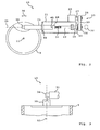
- Fig. 2 is a partially cut plan view of the off Fig. 1 apparent adjusting drive 13 according to a first embodiment of the invention can be seen, which comprises a threaded spindle mechanism.
- the adjusting drive 13 has a spindle nut 18, which is articulated by means of an actuating member 31 on the rotor blade 9.
- an external thread 32 having a threaded spindle 19 is screwed, which is rotatably connected to a shaft 33.
- the shaft 33 is rotatably supported about its longitudinal axis 25, which coincides with the longitudinal axis of the threaded spindle 19, by means of a bearing 20 on a holder 21 designed as a housing and preferably secured in the axial direction.
- An electric drive 22 is attached to the bracket 21 and coupled by means of a gear 23 with the shaft 33 so that it is rotated by the drive 22 about its longitudinal axis 25 or can be. Due to the rotationally fixed connection of the threaded spindle 19 with the shaft 33 and the threaded spindle 19 is rotatable about the longitudinal axis 25.
- the drive 22 preferably comprises an electric motor and, for example, has a rated speed between 3600 and 4800 revolutions per minute.
- the gear 23 is designed as a belt drive and has a non-rotatably seated on the shaft 33 pulley 26, a non-rotatably connected to the drive shaft 27 of the drive 22 pulley 28 and a belt 29 which sits on the two pulleys 26 and 28.
- the shaft 33 forms here simultaneously the output shaft 50 (see Fig. 4
- the output shaft 50 is also possible to form the output shaft 50 as a separate component, which is rotatably coupled to the shaft 33.
- the transmission 23 preferably forms a synchronous belt drive and has For example, a gear ratio of 1: 4.
- the gear 23 may be formed as a chain drive, wherein the pulleys 26 and 28 are replaced by a sprocket and the belt 29 by a chain.
- a position sensor 30 which is coupled to the shaft 33 and the rotation of the shaft 33 characterizing electrical signal to the wind turbine controller 17 outputs or can deliver.
- the spindle nut 18 is not rotatable about the axis 25, in particular because it is coupled via the actuator 31 with the rotor blade 9. Additionally or alternatively, the spindle nut 18 and / or the actuator 31 but also on the holder 21 against rotation about the axis 25 may be secured. Now, if the threaded spindle 19 is rotated about the axis 25, the spindle nut 18 moves together with the actuator 31 along the axis 25, resulting in a rotation of the rotor blade 9 to the blade axis 11 relative to the rotor hub 8 results.
- a liquid lubricant 51 (see Fig. 6 ) brought in. Since, when the rotor 6 rotates about the rotor axis 7, the adjusting drive 13 also rotates, the threaded spindle 19 is automatically lubricated.
- Fig. 3 shows a partial side view of the adjusting drive 13, wherein it is seen that the actuator 31 has at its end facing away from the spindle nut 18, a connecting piece 34 which is connected by means of a joint 35 formed here as a ball joint with the rotor blade 9.
- FIG. 4 A partially sectioned side view of the threaded spindle mechanism shows Fig. 4 , It can be seen that the holder 21 is connected by two elastomeric bearings 36 and 37 with the rotor hub 8.
- Each elastomeric bearing comprises an inner part 38 rigidly connected to the holder 21, an outer sleeve 39 surrounding the inner part 38 and an elastomeric body 40 surrounding the inner part 38 and arranged in the outer sleeve 39, by means of which the inner part 38 is connected to the outer sleeve 39.
- the outer sleeve can be omitted, so that the elastomer body 40 sits directly in a recess provided in the rotor hub 8.
- the elastomeric bearings 36 and 37 allow pivoting of the holder 21 about a pivot axis 41 which is perpendicular to the longitudinal axis 25 and parallel to the blade axis 11 here.
- the elastomeric bearings allow limited damped movements in other directions, in particular translatory movements and / or tilting movements. A jamming of the adjustment can thus be counteracted.
- elastomeric bearings are usually low maintenance and durable.
- the joint 35 can be formed as an elastomer bearing.
- the threaded spindle 19 has at its end facing the shaft 33, a flange 42 which is rotatably connected by means of releasable fastening means 44 with a provided on one of the threaded spindle 19 end of the shaft 33 flange 43, which are preferably designed as a threaded bolt.
- the flange 42 is rigid with the threaded spindle 19 and the flange 43 is rigidly connected to the shaft 33 so that a rotational movement of the shaft 33 about the longitudinal axis 25 on the threaded spindle 19 is transferable.
- the threaded spindle 19 can be separated from the shaft 33 by releasing the fastening means 44.
- the spindle nut 18 is screwed into the actuator 31 and by means of a securing pin 45 which engages through the wall of the actuator 31 and engages in a hole provided in the spindle nut 18, secured to the actuator 31 (see Fig. 5 ).
- the locking pin 45 is removed or at least brought out of engagement with the spindle nut 18, so that the spindle nut 18 unscrewed from the actuator 31 can be.
- the spindle nut 18 is separable from the actuator 31.
- the actuator 31 is formed as a tube which is guided by means of a guide 46 in the direction of the arrow 24 slidably on the holder 21.
- Fig. 5 a partial sectional view of the actuator 31 along the longitudinal axis 25 is shown, so that the principle of securing the spindle nut 18 on the actuator 31 by means of the locking pin 45 is clear. It is clear to those skilled in the art that the locking pin 45 can hold the spindle nut 18 against rotation on the actuating member 31 in principle and axially secure when the spindle nut 18 and the actuator 31 are assembled without screwing. Furthermore, a plurality of locking pins may be provided around the longitudinal axis 25.
- Fig. 6 shows a partially sectioned side view of the adjusting drive 13, wherein the locking pin 45 has been removed and the threaded spindle 19 and the spindle nut 18 were dismantled.
- the dismantled assembly 52 of threaded spindle 19 and spindle nut 18 is in Fig. 7 shown, wherein the reference numeral 53 denotes the external thread of the spindle nut 18, by means of which it can be screwed into the actuator 31.
- Fig. 8 is a partial side view of the adjustment drive 13 can be seen, wherein a cover 54 has an opening 55 (see Fig. 9 ) of the housing 21 covers.
- the cover 54 is pivotally mounted by hinges 56 on the housing 21 and thus formed as a flap, so that by pivoting the cover 54, the housing opening 55 is releasable.
- the cover 54 but also be removable, so that the hinges can be omitted.
- Im out Fig. 8 apparent, closed state of the cover 54, this seals the opening 55 sealing so that no lubricant 51 escape from the housing 21 and no impurities can enter the housing 21.
- the cover 54 is secured in the closed state to the housing 21 against accidental release or pivoting by a lock 57.
- the lock 57 is released and the cover 54 is pivoted open, so that the opening 55 is released.
- maintenance on the Threaded spindle mechanism can be performed.
- through the opening 55 through the assembly 52 can be removed and assembled.
- the adjusting drive 14 is formed corresponding to the adjusting drive 13.
- Fig. 10 is a schematic view of the Fig. 1 apparent and designed as a threaded spindle mechanism adjustment drive 13 according to a second embodiment of the invention can be seen, wherein identical to the first embodiment, or similar features with the same reference numerals as in the first embodiment.
- the gear 23 is formed as a gear transmission and has a non-rotatably mounted on the shaft 33 gear 47, a non-rotatably connected to the drive shaft 27 of the drive gear 22 and a 48 designed as a gear idler 49, which with the gears 47 and 48 combs.
- the gear 47 directly to the gear 48.
- the intermediate 49 can be omitted.
- the gears 47 and 48 are coupled together with the interposition of a plurality of gears.
- Fig. 11 is a schematic view of the Fig. 1 apparent and designed as a threaded spindle mechanism adjustment drive 13 according to a third embodiment of the invention can be seen, wherein identical or similar features to the first embodiment are denoted by the same reference numerals as in the first embodiment.
- the gear 23 is formed as a planetary gear, so that the threaded spindle 19, the shaft 33, the gear 23 and the drive 22 in the direction of the longitudinal axis 25 are arranged one behind the other. Spatially, this results in a very slim design of the adjustment 13.
- the planetary gear is preferably single-stage.
Description
Die Erfindung betrifft einen Rotor für eine Windenergieanlage, mit einer Rotornabe, wenigstens einem an der Rotornabe um eine Blattachse drehbar gelagerten Rotorblatt, wenigstens einem Gewindespindel-Mechanismus, der zwischen die Rotornabe und das Rotorblatt geschaltet und sowohl mit der Rotornabe als auch mit dem Rotorblatt verbunden ist, wobei das Rotorblatt durch Betätigen des Gewindespindel-Mechanismus relativ zu der Rotornabe um die Blattachse gedreht wird oder werden kann.The invention relates to a rotor for a wind turbine, with a rotor hub, at least one rotatably mounted on the rotor hub about a blade axis rotor blade, at least one threaded spindle mechanism connected between the rotor hub and the rotor blade and connected to both the rotor hub and the rotor blade is, wherein the rotor blade is rotated by operating the threaded spindle mechanism relative to the rotor hub about the blade axis or can be.
Die
Die
Die
In der
Gewindespindel-Mechanismen, die in Blattwinkelverstellantrieben von Rotoren von Windkraftanlagen eingesetzt werden, unterliegen einem nicht unerheblichen Verschleiß und müssen daher häufiger ausgetauscht werden, was mit Materialkosten, Montagekosten und mit Kosten für den Anlagenstillstand verbunden ist.Leadscrew mechanisms used in blade pitch actuators of wind turbine rotors are subject to significant wear and therefore require frequent replacement, which involves material costs, assembly costs, and equipment downtime.
Ausgehend hiervon liegt der Erfindung die Aufgabe zugrunde, bei einem Rotor der eingangs genannten Art die mit dem Verschleiß des wenigstens einen Gewindespindel-Mechanismus verbundenen Kosten reduzieren zu können.Proceeding from this, the present invention seeks to reduce the costs associated with the wear of at least one threaded spindle mechanism in a rotor of the type mentioned.
Diese Aufgabe wird erfindungsgemäß durch einen Rotor nach Anspruch 1 gelöst. Bevorzugte Weiterbildungen der Erfindung sind in den Unteransprüchen gegeben.This object is achieved by a rotor according to
Der erfindungsgemäße Rotor für eine Windenergieanlage weist eine Rotornabe, wenigstens ein an der Rotornabe um eine Blattachse drehbar gelagertes Rotorblatt und wenigstens einen Gewindespindel-Mechanismus auf, der zwischen die Rotornabe und das Rotorblatt geschaltet und sowohl mit der Rotornabe als auch mit dem Rotorblatt verbunden ist, wobei das Rotorblatt durch Betätigen des Gewindespindel-Mechanismus relativ zu der Rotornabe um die Blattachse gedreht wird oder werden kann, und wobei der Gewindespindel-Mechanismus einen Antrieb, ein Betätigungsglied, eine lösbar mit dem Betätigungsglied gekoppelte Spindelmutter und eine mittels des Antriebs um ihre Längsachse drehbare Gewindespindel aufweist, die lösbar mit dem Antrieb gekoppelt ist, sodass die Gewindespindel und die Spindelmutter von dem Gewindespindel-Mechanismus trennbar sind.The rotor for a wind energy plant according to the invention has a rotor hub, at least one rotor blade rotatably mounted on the rotor hub about a blade axis, and at least one threaded spindle mechanism connected between the rotor hub and the rotor blade and connected to both the rotor hub and the rotor blade, wherein the rotor blade is or can be rotated about the blade axis by actuating the threaded spindle mechanism relative to the rotor hub, and wherein the threaded spindle mechanism comprises a drive, an actuator, a spindle nut releasably coupled to the actuator, and rotatable about its longitudinal axis by the drive Has threaded spindle which is releasably coupled to the drive, so that the threaded spindle and the spindle nut are separable from the threaded spindle mechanism.
Es hat sich herausgestellt, dass bei einem als Blattwinkelverstellantrieb genutzten Gewindespindel-Mechanismus der Verschleiß hauptsächlich an der Gewindespindel und an der Spindelmutter auftritt. Durch die erfindungsgemäße Ausgestaltung des Rotors ist die Gewindespindel zusammen mit der Spindelmutter austauschbar, ohne den gesamten Gewindespindel-Mechanismus demontieren und/oder austauschen zu müssen. Hierdurch können Montagekosten eingespart werden. Ferner können Materialkosten eingespart werden, da andere Komponenten des Gewindespindel-Mechanismus, wie z.B. der Antrieb, weiterbenutzt werden können.It has been found that when used as Blattwinkelverstellantrieb threaded spindle mechanism, the wear occurs mainly on the threaded spindle and the spindle nut. Due to the inventive design of the rotor, the threaded spindle is interchangeable with the spindle nut without having to disassemble the entire threaded spindle mechanism and / or replace. As a result, installation costs can be saved. Furthermore, material costs can be saved since other components of the threaded spindle mechanism, such as e.g. the drive can continue to be used.
Die Gewindespindel und die Spindelmutter bilden eine Baugruppe, die insbesondere zwischen den Antrieb und das Betätigungsglied geschaltet ist. Bevorzugt ist die Gewindespindel zusammen mit der Spindelmutter, also bevorzugt die Baugruppe als Ganzes, von dem Gewindespindel-Mechanismus trennbar. Die Gewindespindel ist mit der Spindelmutter insbesondere schraubverbunden. Bevorzugt ist die Spindelmutter auf die Gewindespindel aufgeschraubt bzw. die Gewindespindel in die Spindelmutter eingeschraubt.The threaded spindle and the spindle nut form an assembly, which is connected in particular between the drive and the actuator. Preferably, the threaded spindle is separable from the threaded spindle mechanism together with the spindle nut, ie preferably the assembly as a whole. The threaded spindle is in particular screw-connected to the spindle nut. Preferably, the spindle nut is screwed onto the threaded spindle or the threaded spindle is screwed into the spindle nut.
Gemäß einer Weiterbildung der Erfindung ist die Gewindespindel außerhalb des Antriebs angeordnet. Somit kann als Antrieb ein herkömmlicher Elektromotor verwendet werden, sodass die Kosten für den Gewindespindel-Mechanismus vergleichsweise gering gehalten werden können. Unter dem Merkmal, dass die Gewindespindel außerhalb des Antriebs angeordnet ist, soll insbesondere verstanden werden, dass der Antrieb und die Gewindespindel separat und/oder räumlich getrennt voneinander angeordnet sind. Dies schließt aber nicht aus, dass die Gewindespindel und der Antrieb vorzugsweise eine enge räumliche Nähe zueinander aufweisen. Der Antrieb umfasst insbesondere eine Antriebswelle, mittels welcher die Gewindespindel um ihre Längsachse drehbar ist.According to one embodiment of the invention, the threaded spindle is arranged outside the drive. Thus, as a drive, a conventional electric motor can be used, so that the cost of the threaded spindle mechanism can be kept relatively low. Under the feature that the threaded spindle is arranged outside the drive, should be understood in particular that the drive and the threaded spindle are arranged separately and / or spatially separated from each other. However, this does not exclude that the threaded spindle and the drive preferably have a close spatial proximity to one another. The drive comprises in particular a drive shaft, by means of which the threaded spindle is rotatable about its longitudinal axis.
Die Gewindespindel ist bevorzugt lösbar an einer Welle befestigt, die mittels des Antriebs um die Längsachse drehbar ist. Insbesondere ist die Gewindespindel durch wenigstens ein Befestigungsmittel lösbar an der Welle befestigt. Das Befestigungsmittel ist oder umfasst z.B. wenigstens eine Schraube, wenigstens einen Schraubbolzen und/oder wenigstens einen Befestigungsbolzen. Gemäß einer Ausgestaltung der Erfindung weisen die Welle und die Gewindespindel jeweils einen Flansch auf, wobei die beiden Flansche lösbar aneinander befestigt sind, insbesondere durch das wenigstens eine Befestigungsmittel. Die Flansche sind vorzugsweise kreis- oder ringförmig und/oder zylinderförmig. In jedem der Flansche ist bevorzugt wenigstens ein Loch vorgesehen, welches zu einem Loch in dem jeweils anderen Flansch fluchtet, wobei in die zueinander fluchtenden Löcher das oder eines der Befestigungsmittel eingreift. Die Flansche sind durch das wenigstens eine Befestigungsmittel vorzugsweise formschlüssig miteinander verbunden. Insbesondere sind die Flansche durch das wenigstens eine Befestigungsmittel miteinander verschraubt. Wegen der lösbaren Befestigung kann die Gewindespindel von der Welle und somit auch von dem Antrieb getrennt werden. Die aus der Gewindespindel und der Spindelmutter gebildete Baugruppe ist insbesondere zwischen die Welle und das Betätigungsglied geschaltet.The threaded spindle is preferably releasably attached to a shaft which is rotatable about the longitudinal axis by means of the drive. In particular, the threaded spindle is fastened detachably to the shaft by at least one fastening means. The fastening means is or comprises eg at least one screw, at least one screw bolt and / or at least one fastening bolt. According to one embodiment of the invention, the shaft and the threaded spindle each have a flange, wherein the two flanges are releasably secured to each other, in particular by the at least one fastening means. The flanges are preferably circular or annular and / or cylindrical. In each of the flanges is preferably provided at least one hole which is aligned with a hole in the respective other flange, wherein in the mutually aligned holes engages the or one of the fastening means. The flanges are preferably connected to each other by the at least one fastening means positively. In particular, the flanges are screwed together by the at least one fastening means. Because of the detachable attachment, the threaded spindle can be separated from the shaft and thus also from the drive. The assembly formed from the threaded spindle and the spindle nut is connected in particular between the shaft and the actuator.
Die Gewindespindel kann direkt mit dem Antrieb und/oder mit der Welle gekoppelt sein. Gemäß einer ersten Variante der Erfindung ist somit die Welle die Antriebswelle des Antriebs oder zwischen die Antriebswelle des Antriebs und die Gewindespindel geschaltet. Bevorzugt weist der Gewindespindel-Mechanismus aber ein Getriebe auf, wobei die Gewindespindel und/oder die Welle unter Zwischenschaltung des Getriebes mit dem Antrieb gekoppelt sind. Gemäß einer zweiten Variante der Erfindung ist somit die Welle eine Abtriebswelle des Getriebes oder zwischen die Abtriebswelle des Getriebes und die Gewindespindel geschaltet. Im letzteren Fall ist die Abtriebswelle bevorzugt mit der Welle gekoppelt. Das Getriebe umfasst bevorzugt ein Zahnradgetriebe, ein Planetengetriebe, einen Kettentrieb und/oder einen Riementrieb oder ist als Zahnradgetriebe, Planetengetriebe, Kettentrieb und/oder Riementrieb ausgebildet.The threaded spindle can be coupled directly to the drive and / or with the shaft. According to a first variant of the invention, the shaft is thus connected to the drive shaft of the drive or between the drive shaft of the drive and the threaded spindle. Preferably, however, the threaded spindle mechanism has a gear, wherein the threaded spindle and / or the shaft are coupled to the drive with the interposition of the transmission. According to a second variant of the invention, the shaft thus an output shaft of the transmission or between the output shaft of the transmission and the threaded spindle is connected. In the latter case, the output shaft is preferably coupled to the shaft. The transmission preferably comprises a gear transmission, a planetary gear, a chain drive and / or a belt drive or is designed as a gear transmission, planetary gear, chain drive and / or belt drive.
Mittels des Antriebs ist die Gewindespindel und/oder die Welle um ihre Längsachse drehbar. Ferner ist die Antriebswelle z.B. direkt oder unter Zwischenschaltung des Getriebes und/oder der Welle mit der Gewindespindel gekoppelt. Insbesondere ist der Antrieb ein elektrischer Antrieb und umfasst bevorzugt einen oder zumindest einen Elektromotor. Die Antriebswelle ist in diesem Fall vorzugsweise die Motorwelle des Elektromotors. Bevorzugt weist der Antrieb wenigstens einen Stator und wenigstens einen relativ zu diesem drehbaren Läufer auf, der drehfest mit der Antriebswelle (Motorwelle) gekoppelt ist und vorzugsweise auf dieser sitzt. Unter dem Merkmal, dass die Gewindespindel außerhalb des Antriebs angeordnet ist, soll hier insbesondere verstanden werden, dass die Gewindespindel außerhalb der von Stator und Läufer und/oder außerhalb der von Stator, Läufer und Antriebswelle gebildeten Baugruppe angeordnet ist.By means of the drive, the threaded spindle and / or the shaft is rotatable about its longitudinal axis. Furthermore, the drive shaft is coupled for example directly or with the interposition of the transmission and / or the shaft with the threaded spindle. In particular, the drive is an electric drive and preferably comprises one or at least one Electric motor. The drive shaft is in this case preferably the motor shaft of the electric motor. Preferably, the drive has at least one stator and at least one rotatable relative to this rotor, which is non-rotatably coupled to the drive shaft (motor shaft) and preferably located on this. Under the feature that the threaded spindle is arranged outside the drive, it should be understood here in particular that the threaded spindle is arranged outside of the stator and rotor and / or outside of the assembly formed by the stator, rotor and drive shaft.
Die Rotornabe und das Rotorblatt bilden insbesondere jeweils ein Bauteil, wobei das Betätigungsglied an einem ersten der Bauteile gelagert und die Gewindespindel und/oder die Welle an einem zweiten der Bauteile gelagert ist. Gemäß einer Weiterbildung der Erfindung ist das Betätigungsglied an dem ersten Bauteil gelenkig gelagert und/oder die Gewindespindel und/oder die Welle ist an dem zweiten Bauteil gelenkig gelagert, sodass ein Verkanten des Gewindespindel-Mechanismus verhindert werden kann. Das Betätigungsglied ist an dem ersten Bauteil vorzugsweise schwenkbar und/oder drehbar gelagert. Ferner ist die Gewindespindel und/oder die Welle an dem zweiten Bauteil vorzugsweise schwenkbar und/oder drehbar gelagert. Die Gewindespindel ist insbesondere um ihre Längsachse drehbar an dem zweiten Bauteil gelagert. Die Bauteile können jeweils einteilig oder mehrteilig sein.The rotor hub and the rotor blade in particular each form a component, wherein the actuating member is mounted on a first of the components and the threaded spindle and / or the shaft is mounted on a second of the components. According to one embodiment of the invention, the actuating member is articulated to the first component and / or the threaded spindle and / or the shaft is articulated to the second component, so that tilting of the threaded spindle mechanism can be prevented. The actuator is preferably pivotally and / or rotatably mounted on the first component. Furthermore, the threaded spindle and / or the shaft is preferably pivotably and / or rotatably mounted on the second component. The threaded spindle is mounted in particular rotatable about its longitudinal axis on the second component. The components can each be in one piece or in several parts.
Bevorzugt ist die Gewindespindel und/oder die Welle mittels einer Halterung an dem zweiten Bauteil gelagert. Gemäß einer Ausgestaltung der Erfindung kann auch die Spindelmutter mittels der Halterung an dem zweiten Bauteil gelagert sein. Vorzugsweise ist das Betätigungsglied an der Halterung verschiebbar geführt.Preferably, the threaded spindle and / or the shaft is mounted by means of a holder on the second component. According to one embodiment of the invention, the spindle nut can also be mounted on the second component by means of the holder. Preferably, the actuator is guided displaceably on the holder.
Die Halterung umfasst oder bildet bevorzugt ein Gehäuse, in dem die Spindelmutter und die Gewindespindel angeordnet sind. Hierdurch können die Gewindespindel und die Spindelmutter vor Verunreinigungen und Feuchtigkeit geschützt werden. Das Gehäuse ist vorzugsweise mit einer Zugangsöffnung versehen, durch welche hindurch die Gewindespindel und/oder die Spindelmutter zugänglich und insbesondere auch austauschbar sind. Ferner weist das Gehäuse bevorzugt eine die Zugangsöffnung abdeckende Abdeckung auf, die vom Gehäuse abnehmbar oder relativ zu diesem bewegbar ist und somit geöffnet werden kann, sodass durch Öffnen der Abdeckung die Zugangsöffnung freigebbar ist. Im geschlossenen Zustand deckt die Abdeckung die Zugangsöffnung vorzugsweise dichtend ab. Insbesondere ist das Betätigungsglied in oder zumindest teilweise in dem Gehäuse angeordnet. Vorzugsweise erstreckt sich das Betätigungsglied aus dem Gehäuse heraus. Bevorzugt ist auch die Welle in oder zumindest teilweise in dem Gehäuse angeordnet.The holder preferably comprises or forms a housing in which the spindle nut and the threaded spindle are arranged. As a result, the threaded spindle and the spindle nut can be protected from contamination and moisture. The housing is preferably provided with an access opening through which the threaded spindle and / or the spindle nut are accessible and, in particular, also exchangeable. Furthermore, the housing preferably has an access opening covering cover, which is removable from the housing or movable relative thereto and thus can be opened, so that by opening the cover, the access opening is releasable. When closed, the cover preferably covers the access opening in a sealing manner. In particular, the actuator is arranged in or at least partially in the housing. Preferably, the actuator extends out of the housing. Preferably, the shaft is arranged in or at least partially in the housing.
Gemäß einer Ausgestaltung der Erfindung ist in das Gehäuse ein Schmiermittel eingebracht, welches insbesondere flüssig ist. Vorzugsweise kann das Schmiermittel im Gehäuseinnenraum, in dem auch die Gewindespindel angeordnet ist, frei fließen. Bei einer Drehung des Rotors um die Rotorachse dreht sich auch der Gewindespindel-Mechanismus um die Rotorachse, sodass eine automatische Schmierung der Gewindespindel und/oder des Gewindespindel-Mechanismus mit dem Schmiermittel erfolgt. Das Schmiermittel ist z.B. durch ein Öl oder dergleichen gebildet.According to one embodiment of the invention, a lubricant is introduced into the housing, which is in particular liquid. Preferably, the lubricant in the housing interior, in which the threaded spindle is arranged to flow freely. Upon rotation of the rotor about the rotor axis, the threaded spindle mechanism rotates about the rotor axis, so that automatic lubrication of the threaded spindle and / or the threaded spindle mechanism is carried out with the lubricant. The lubricant is e.g. formed by an oil or the like.
Die Halterung ist insbesondere gelenkig an dem zweiten Bauteil gelagert, vorzugsweise schwenkbar und/oder drehbar. Hierdurch kann die gelenkige Lagerung der Gewindespindel und/oder der Welle an dem zweiten Bauteil realisiert werden. Die gelenkige Lagerung der Halterung an dem zweiten Bauteil erfolgt z.B. um wenigstens eine Gelenkachse, die insbesondere senkrecht zur Längsachse der Gewindespindel verläuft. Gemäß einer Weiterbildung der Erfindung erfolgt die gelenkige Lagerung der Halterung an dem zweiten Bauteil um wenigstens zwei Gelenkachsen, die insbesondere senkrecht zur Längsachse der Gewindespindel und senkrecht zueinander verlaufen. Die gelenkige Lagerung des Betätigungsglieds an dem ersten Bauteil erfolgt z.B. um wenigstens eine Gelenkachse, die insbesondere senkrecht zur Längsachse der Gewindespindel verläuft. Bevorzugt erfolgt die gelenkige Lagerung des Betätigungsglieds an dem ersten Bauteil aber um wenigstens zwei Gelenkachsen, die insbesondere senkrecht zur Längsachse der Gewindespindel und senkrecht zueinander verlaufen.The holder is in particular hingedly mounted on the second component, preferably pivotable and / or rotatable. In this way, the articulated mounting of the threaded spindle and / or the shaft can be realized on the second component. The articulated mounting of the holder on the second component takes place, for example, about at least one hinge axis, which extends in particular perpendicular to the longitudinal axis of the threaded spindle. According to one embodiment of the invention, the articulated mounting of the holder takes place on the second component about at least two hinge axes, in particular perpendicular to the longitudinal axis of the threaded spindle and perpendicular to each other. The articulated mounting of the actuating member on the first component takes place, for example, about at least one hinge axis, which extends in particular perpendicular to the longitudinal axis of the threaded spindle. However, the articulated mounting of the actuating member on the first component preferably takes place about at least two joint axes, which in particular run perpendicular to the longitudinal axis of the threaded spindle and perpendicular to one another.
Das Betätigungsglied ist insbesondere an dem Rotorblatt und die Gewindespindel und/oder die Welle und/oder die Halterung ist insbesondere an der Rotornabe gelagert, sodass das erste Bauteil von dem Rotorblatt und das zweite Bauteil von der Rotornabe gebildet ist. Es ist aber auch eine umgekehrte Anordnung möglich, sodass das zweite Bauteil von dem Rotorblatt und das erste Bauteil von der Rotornabe gebildet ist.The actuator is in particular on the rotor blade and the threaded spindle and / or the shaft and / or the holder is mounted in particular on the rotor hub, so that the first component is formed by the rotor blade and the second component of the rotor hub. But it is also a reverse arrangement possible, so that the second component is formed by the rotor blade and the first component of the rotor hub.
Ein Verkanten des Gewindespindel-Mechanismus kann zum einen in einer Querschnittsebene des Rotorblatts, zum anderen aber auch senkrecht dazu erfolgen. Bevorzugt ist das Betätigungsglied mittels wenigstens eines ersten Gelenks gelenkig an dem ersten Bauteil und/oder die Halterung mittels wenigstens eines zweiten Gelenks gelenkig an dem zweiten Bauteil gelagert, wobei jedes der Gelenke einen, zwei oder wenigstens zwei Rotationsfreiheitsgrade besitzt. Jedes der Gelenke kann z.B. ein Kreuzgelenk, ein Kugelgelenk, ein Drehgelenk oder ein Elastomerlager sein. Ferner kann das erste Gelenk unterschiedlich zu dem zweiten Gelenk ausgebildet sein.A tilting of the threaded spindle mechanism can be done on the one hand in a cross-sectional plane of the rotor blade, on the other hand, but also perpendicular thereto. Preferably, the actuating member by means of at least one first joint articulated on the first component and / or the holder is mounted by means of at least one second joint hinged to the second component, each of the joints has one, two or at least two rotational degrees of freedom. Each of the joints can e.g. a universal joint, a ball joint, a swivel joint or an elastomeric bearing. Furthermore, the first joint may be formed differently from the second joint.
Bevorzugt ist die Halterung mittels wenigstens eines Elastomerlagers gelenkig an dem zweiten Bauteil gelagert. Das oder jedes der Elastomerlager umfasst bevorzugt ein Innenteil, ein das Innenteil umringendes Außenteil und einen das Innenteil umgebenden und in dem Außenteil sitzenden Elastomerkörper, mittels welchem das Innenteil mit dem Außenteil verbunden ist. Der Elastomerkörper ist mit dem Innenteil z.B. stoffschlüssig, reibschlüssig oder gleitend verbunden. Ferner ist der Elastomerkörper mit dem Außenteil z.B. stoffschlüssig, reibschlüssig oder gleitend verbunden. Bevorzugt ist das Innenteil mit der Halterung und das Außenteil mit dem zweiten Bauteil fest verbunden. Insbesondere ist das Innenteil starr mit der Halterung verbunden und/oder einstückig mit dieser ausgebildet. Alternativ kann aber auch das Außenteil mit der Halterung und das Innenteil mit dem zweiten Bauteil fest verbunden sein. Das Außenteil ist bevorzugt eine Hülse. Ergänzend oder alternativ kann das Außenteil durch das zweite Bauteil oder durch die Halterung gebildet sein. Gemäß einer Weiterbildung der Erfindung ist das Betätigungsglied mittels wenigstens eines Elastomerlagers an dem ersten Bauteil gelagert. Elastomerlager sind wartungsarm und weisen eine relativ hohe Lebensdauer auf. Insbesondere bieten Elastomerlager den Vorteil, dass sie in der Regel nicht geschmiert werden müssen.Preferably, the holder is mounted by means of at least one elastomeric bearing articulated on the second component. The or each of the elastomeric bearings preferably comprises an inner part, an outer part surrounding the inner part and an elastomer body surrounding the inner part and seated in the outer part, by means of which the inner part is connected to the outer part. The elastomeric body is connected to the inner part, for example, a material fit, frictional engagement or sliding. Furthermore, the elastomeric body with the outer part, for example, cohesive, frictionally engaged or slidably connected. Preferably, the inner part with the holder and the outer part with the second component is firmly connected. In particular, the inner part is rigidly connected to the holder and / or formed integrally therewith. Alternatively, however, the outer part with the holder and the inner part with the second component can be firmly connected. The outer part is preferably a sleeve. Additionally or alternatively, the outer part may be formed by the second component or by the holder. According to one embodiment of the invention, the actuating member is mounted by means of at least one elastomeric bearing on the first component. Elastomeric bearings are low maintenance and have a relatively long service life. In particular, elastomeric bearings offer the advantage that they usually do not need to be lubricated.
Die Gewindespindel und/oder die Welle ist bevorzugt mittels wenigstens eines Lagers um ihre Längsachse drehbar an der Halterung gelagert. Insbesondere handelt es sich bei dem wenigstens einen Lager um ein Wälzlager, alternativ kann das Lager aber auch als Gleitlager ausgebildet sein. Das Lager ist vorzugsweise an der Halterung vorgesehen. Gemäß einer Weiterbildung der Erfindung ist die Gewindespindel und/oder die Welle an dem Lager oder an einem zusätzlichen Lager in axialer Richtung gesichert oder festgelegt. Die axiale Richtung bezeichnet hierbei insbesondere die Richtung der Längsachse der Gewindespindel und/oder der Welle.The threaded spindle and / or the shaft is preferably mounted rotatably on the holder by means of at least one bearing about its longitudinal axis. In particular, the at least one bearing is a roller bearing, but alternatively the bearing may also be designed as a sliding bearing. The bearing is preferably provided on the holder. According to one embodiment of the invention, the threaded spindle and / or the shaft is secured or fixed to the bearing or to an additional bearing in the axial direction. The axial direction here refers in particular to the direction of the longitudinal axis of the threaded spindle and / or the shaft.
Das wenigstens eine Lager und/oder der Antrieb und/oder das Getriebe ist bevorzugt an der Halterung befestigt. Hierdurch können unerwünschte Abstandsänderungen zwischen dem Antrieb und der Gewindespindel vermieden werden. Bevorzugt ist auch das zusätzliche Lager an der Halterung befestigt, sofern dieses vorhanden ist.The at least one bearing and / or the drive and / or the transmission is preferably fastened to the holder. As a result, undesirable changes in the distance between the drive and the threaded spindle can be avoided. Preferably, the additional bearing is attached to the holder, if this is available.
Der Gewindespindel-Mechanismus weist bevorzugt einen Positionsgeber auf, mittels welchem z.B. die Verdrehung des Rotorblatts relativ zu der Rotornabe ermittelt wird oder werden kann. Insbesondere ist die Gewindespindel, vorzugsweise unter Zwischenschaltung der Welle, mit dem Positionsgeber verbunden. Es kann aber auch eine Getriebewelle oder die Antriebswelle mit dem Positionsgeber verbunden sein.The threaded spindle mechanism preferably has a position sensor, by means of which e.g. the rotation of the rotor blade relative to the rotor hub is or can be determined. In particular, the threaded spindle, preferably with the interposition of the shaft, connected to the position sensor. But it can also be a transmission shaft or the drive shaft connected to the position sensor.
Das Betätigungsglied ist bevorzugt als Rohr oder zumindest teilweise hohl ausgebildet. Die hohle Ausbildung des Betätigungsglieds hat den Vorteil, dass die Gewindespindel in den Hohlraum des Betätigungsglieds eintauchen kann.The actuator is preferably formed as a tube or at least partially hollow. The hollow design of the actuator has the advantage that the threaded spindle can dip into the cavity of the actuator.
Gemäß einer Weiterbildung der Erfindung ist die Spindelmutter an dem Betätigungsglied mittels einer Schraubverbindung befestigt. Da die Schraubverbindung lösbar ist, kann die Spindelmutter von dem Betätigungsglied getrennt werden, sodass die Spindelmutter lösbar mit dem Betätigungsglied gekoppelt ist. Insbesondere weist das Betätigungsglied ein Innengewinde auf, welches mit einem an der Spindelmutter vorgesehenen Außengewinde ineinandergreift. Ergänzend oder alternativ können die Spindelmutter und das Betätigungsglied aber auch zusammengesteckt oder durch Schrauben oder Bolzen aneinander befestigt sein. Bevorzugt ist die Verbindung zwischen der Spindelmutter und dem Betätigungsglied durch einen Sicherungsstifts, vorzugsweise formschlüssig, gegen Lösen gesichert. Der Sicherungsstift greift z.B. in eine in der Spindelmutter vorgesehene Ausnehmung ein oder durchgreift diese Ausnehmung. Ferner greift der Sicherungsstift z.B. in eine in dem Betätigungsglied vorgesehene Ausnehmung ein oder durchgreift diese Ausnehmung.According to one embodiment of the invention, the spindle nut is attached to the actuator by means of a screw connection. Since the screw is detachable, the spindle nut can be separated from the actuator, so that the spindle nut is releasably coupled to the actuator. In particular, the actuating member has an internal thread which engages with an external thread provided on the spindle nut. Additionally or alternatively, the spindle nut and the Actuator but also plugged together or fastened by screws or bolts together. The connection between the spindle nut and the actuating member is preferably secured against loosening by a securing pin, preferably in a form-fitting manner. The locking pin, for example, engages in a recess provided in the spindle nut or passes through this recess. Further, the locking pin engages, for example, in a recess provided in the actuating member or passes through this recess.
Die Gewindespindel und die Spindelmutter bilden bevorzugt einen Rollengewindetrieb und sind entsprechend ausgebildet. Hierdurch können hohe Kräfte bei geringer Reibung übertragen werden. Ferner weisen Rollengewindetriebe eine relativ hohe Lebensdauer bei hoher Zuverlässigkeit auf. Insbesondere sind Rollengewindetriebe auch noch bei unzureichender Schmierung funktionsfähig, was zusätzliche Funktionssicherheit bietet. Vorzugsweise bilden die Gewindespindel und die Spindelmutter einen Planetenrollengewindetrieb. Derartige Gewindetriebe sind z.B. aus einem Katalog der SKF-Gruppe, Druckschrift 4351
Die Rotornabe ist insbesondere um eine Rotorachse drehbar, wobei die Blattachse des Rotorblatts bevorzugt quer oder im Wesentlichen quer zur Rotorachse verläuft.The rotor hub is in particular rotatable about a rotor axis, wherein the blade axis of the rotor blade preferably extends transversely or substantially transversely to the rotor axis.
Gemäß einer Ausgestaltung der Erfindung umfasst der Rotor wenigstens einen zwischen die Rotornabe und das Rotorblatt geschalteten Blattwinkelverstellantrieb, mittels welchem das Rotorblatt um seine Blattachse drehbar ist, wobei der Blattwinkelverstellantrieb den wenigstens einen Gewindespindel-Mechanismus aufweist oder durch diesen gebildet ist. Die Gewindespindel ist durch das wenigstens eine Befestigungsmittel lösbar in dem Blattwinkelverstellantrieb befestigt, sodass die Gewindespindel und die dazugehörige Spindelmutter von dem Rest des Blattwinkelverstellantriebs getrennt werden können.According to one embodiment of the invention, the rotor comprises at least one Blattwinkelverstellantrieb connected between the rotor hub and the rotor blade, by means of which the rotor blade is rotatable about its blade axis, wherein the Blattwinkelverstellantrieb has the at least one threaded spindle mechanism or is formed by this. The threaded spindle is releasably secured in the Blattwinkelverstellantrieb by the at least one fastening means, so that the threaded spindle and the associated spindle nut can be separated from the rest of the Blattwinkelverstellantriebs.
Der Rotor kann mehrere Rotorblätter aufweisen, die jeweils um eine Blattachse drehbar an der Rotornabe gelagert sind. Zwischen die Rotornabe und die Rotorblätter kann jeweils mindestens ein Gewindespindel-Mechanismus geschaltet und sowohl mit der Rotornabe als auch mit dem jeweiligen Rotorblatt verbunden sein, wobei jedes der Rotorblätter durch Betätigen des jeweiligen Gewindespindel-Mechanismus relativ zu der Rotornabe um die jeweilige Blattachse drehbar ist. Jeder der Gewindespindel-Mechanismen kann, wie beschrieben, weitergebildet sein.The rotor may have a plurality of rotor blades, which are each mounted rotatably about a blade axis on the rotor hub. At least one threaded spindle mechanism can be connected between the rotor hub and the rotor blades and both with the rotor hub and to be connected to the respective rotor blade, wherein each of the rotor blades is rotatable by operating the respective threaded spindle mechanism relative to the rotor hub about the respective blade axis. Each of the threaded spindle mechanisms may be further developed as described.
Die Erfindung betrifft ferner eine Windenergieanlage mit einem Maschinenträger und einem an dem Maschinenträger um eine Rotorachse drehbar gelagerten und mittels Windkraft angetriebenen oder antreibbaren Rotor, der mit einem elektrischen Generator mechanisch gekoppelt ist, der von dem Rotor angetrieben wird oder werden kann. Bei dem Rotor handelt es sich bevorzugt um einen erfindungsgemäßen Rotor, der gemäß allen genannten Ausgestaltungen weitergebildet sein kann. Mittels des Gewindespindel-Mechanismus ist das wenigstens eine Rotorblatt relativ zur Rotornabe um seine Blattachse drehbar und dadurch die Drehzahl des Rotors, und somit vorzugsweise auch die Drehzahl des Generators, variierbar.The invention further relates to a wind energy plant with a machine carrier and a rotatably mounted on the machine frame about a rotor axis and driven by wind power or driven rotor, which is mechanically coupled to an electric generator which is driven by the rotor or can be. The rotor is preferably a rotor according to the invention, which can be developed according to all mentioned embodiments. By means of the threaded spindle mechanism, the at least one rotor blade is rotatable relative to the rotor hub about its blade axis and thereby the rotational speed of the rotor, and thus preferably also the rotational speed of the generator, variable.
Die Erfindung betrifft ebenfalls die Verwendung eines Rotors zur Variation der Rotordrehzahl einer Windenergieanlage mit einem Maschinenträger, an dem der um eine Rotorachse und mittels Windkraft angetriebene Rotor drehbar gelagert und mit einem elektrischen Generator mechanisch gekoppelt ist, der von dem Rotor angetrieben wird. Bei dem Rotor handelt es sich bevorzugt um einen erfindungsgemäßen Rotor, der gemäß allen genannten Ausgestaltungen weitergebildet sein kann. Insbesondere wird durch Betätigen des Gewindespindelmechanismus das wenigstens eine Rotorblatt relativ zur Rotornabe um seine Blattachse gedreht, sodass sich die Drehzahl des Rotors, und somit vorzugsweise auch die Drehzahl des Generators, ändert.The invention also relates to the use of a rotor for varying the rotor speed of a wind turbine with a machine carrier on which the rotor driven by a rotor axis and by wind power is rotatably mounted and mechanically coupled to an electrical generator which is driven by the rotor. The rotor is preferably a rotor according to the invention, which can be developed according to all mentioned embodiments. In particular, by operating the threaded spindle mechanism, the at least one rotor blade is rotated relative to the rotor hub about its blade axis, so that the rotational speed of the rotor, and thus preferably also the rotational speed of the generator, changes.
Die Erfindung wird nachfolgend anhand bevorzugter Ausführungsformen unter Bezugnahme auf die Zeichnung beschrieben. In der Zeichnung zeigen:
- Fig. 1
- eine schematische Darstellung einer Windenergieanlage mit einem erfindungsgemäßen Rotor,
- Fig. 2
- eine schematische und teilweise geschnittene Draufsicht auf einen Verstellantrieb gemäß einer ersten Ausführungsform der Erfindung,
- Fig. 3
- eine schematische und teilweise Seitenansicht des Verstellantriebs nach
Fig. 2 , - Fig. 4
- eine schematische und teilweise geschnittene Seitenansicht des Gewindespindel-Mechanismus nach
Fig. 2 , - Fig. 5
- eine schematische und teilweise Schnittansicht des Betätigungsglieds und der Spindelmutter nach
Fig. 2 entlang der Drehachse der Gewindespindel, - Fig. 6
- die Seitenansicht nach
Fig. 4 mit demontierter Gewindespindel, - Fig. 7
- eine Seitenansicht der demontierten Gewindespindel,
- Fig. 8
- eine schematische Seitenansicht des Gewindespindel-Mechanismus im geschlossenen Zustand des Gehäuses,
- Fig. 9
- eine schematische Seitenansicht des Gewindespindel-Mechanismus im geöffneten Zustand des Gehäuses,
- Fig. 10
- eine schematische Draufsicht auf einen Verstellantrieb gemäß einer zweiten Ausführungsform der Erfindung und
- Fig. 11
- eine schematische Draufsicht auf einen Verstellantrieb gemäß einer dritten Ausführungsform der Erfindung.
- Fig. 1
- a schematic representation of a wind turbine with a rotor according to the invention,
- Fig. 2
- a schematic and partially sectioned plan view of an adjustment according to a first embodiment of the invention,
- Fig. 3
- a schematic and partial side view of the adjusting drive according to
Fig. 2 . - Fig. 4
- a schematic and partially sectioned side view of the threaded spindle mechanism according to
Fig. 2 . - Fig. 5
- a schematic and partial sectional view of the actuator and the spindle nut after
Fig. 2 along the axis of rotation of the threaded spindle, - Fig. 6
- the side view after
Fig. 4 with dismantled threaded spindle, - Fig. 7
- a side view of the dismantled threaded spindle,
- Fig. 8
- a schematic side view of the threaded spindle mechanism in the closed state of the housing,
- Fig. 9
- a schematic side view of the threaded spindle mechanism in the open state of the housing,
- Fig. 10
- a schematic plan view of an adjustment according to a second embodiment of the invention and
- Fig. 11
- a schematic plan view of an adjustment according to a third embodiment of the invention.
Aus
Aus
Die Spindelmutter 18 ist nicht um die Achse 25 drehbar, insbesondere da sie über das Betätigungsglied 31 mit dem Rotorblatt 9 gekoppelt ist. Ergänzend oder alternativ kann die Spindelmutter 18 und/oder das Betätigungsglied 31 aber auch an der Halterung 21 gegen ein Verdrehen um die Achse 25 gesichert sein. Wird nun die Gewindespindel 19 um die Achse 25 gedreht, so verschiebt sich die Spindelmutter 18 zusammen mit dem Betätigungsglied 31 entlang der Achse 25, woraus eine Verdrehung des Rotorblatts 9 um die Blattachse 11 relativ zur Rotornabe 8 resultiert. Wird der Drehsinn der Gewindespindel 19 umgekehrt, so wird die Spindelmutter 18 zusammen mit dem Betätigungsglied 31 in die entgegengesetzte Richtung entlang der Achse 25 verschoben, woraus eine Verdrehung des Rotorblatts 9 um die Blattachse 11 in die entgegengesetzte Richtung resultiert. Die einander entgegengesetzten Richtungen, in welche die Spindelmutter 18 zusammen mit dem Betätigungsglied 31 entlang der Achse 25 bewegt werden kann, sind mit dem Doppelpfeil 24 angedeutet.The
In das Gehäuse 21 ist ein flüssiges Schmiermittel 51 (siehe
Eine teilweise geschnittene Seitenansicht des Gewindespindel-Mechanismus zeigt
Die Gewindespindel 19 weist an ihrem der Welle 33 zugewandten Ende einen Flansch 42 auf, der mit einem an einem der Gewindespindel 19 zugewandten Ende der Welle 33 vorgesehenen Flansch 43 durch lösbare Befestigungsmittel 44 drehfest verbunden ist, die vorzugsweise als Schraubbolzen ausgebildet sind. Der Flansch 42 ist starr mit der Gewindespindel 19 und der Flansch 43 ist starr mit der Welle 33 verbunden, sodass eine Drehbewegung der Welle 33 um die Längsachse 25 auf die Gewindespindel 19 übertragbar ist. Die Gewindespindel 19 kann durch Lösen der Befestigungsmittel 44 von der Welle 33 getrennt werden.The threaded
Die Spindelmutter 18 ist in das Betätigungsglied 31 eingeschraubt und mittels eines Sicherungsstifts 45, der die Wandung des Betätigungsglieds 31 durchgreift und in ein in der Spindelmutter 18 vorgesehenes Loch eingreift, an dem Betätigungsglied 31 gesichert (siehe
In
Aus
Der Verstellantrieb 14 ist entsprechend zum Verstellantrieb 13 ausgebildet.The adjusting
Aus
Aus
- 11
- WindenergieanlageWind turbine
- 22
- Fundamentfoundation
- 33
- Turmtower
- 44
- Maschinenhauspower house
- 55
- Maschinenträgermachine support
- 66
- Rotorrotor
- 77
- Rotorachserotor axis
- 88th
- Rotornaberotor hub
- 99
- Rotorblattrotor blade
- 1010
- Rotorblattrotor blade
- 1111
- Blattachseblade axis
- 1212
- Blattachseblade axis
- 1313
- Verstellantriebadjustment
- 1414
- VerstallantriebVerstallantrieb
- 1515
- Windwind
- 1616
- Generatorgenerator
- 1717
- WindenergieanlagensteuerungWind turbine control
- 1818
- Spindelmutterspindle nut
- 1919
- Gewindespindelscrew
- 2020
- Lager / WälzlagerBearings / Rolling Bearings
- 2121
- Halterungbracket
- 2222
- elektrischer Antriebelectric drive
- 2323
- Getriebetransmission
- 2424
- Bewegungsrichtung der Spindelmutter und des BetätigungsgliedsDirection of movement of the spindle nut and the actuator
- 2525
- Längsachse / Drehachse der Welle und der GewindespindelLongitudinal axis / axis of rotation of the shaft and the threaded spindle
- 2626
- Riemenscheibe / KettenradPulley / sprocket
- 2727
- Welle des AntriebsShaft of the drive
- 2828
- Riemenscheibe / KettenradPulley / sprocket
- 2929
- Riemen / KetteBelt / chain
- 3030
- Positionsgeberlocator
- 3131
- Betätigungsgliedactuator
- 3232
- Außengewinde der GewindespindelExternal thread of the threaded spindle
- 3333
- Wellewave
- 3434
- Anschlussstück des BetätigungsgliedsConnecting piece of the actuator
- 3535
- Gelenkjoint
- 3636
- Elastomerlagerelastomeric bearings
- 3737
- Elastomerlagerelastomeric bearings
- 3838
- Innenteilinner part
- 3939
- Außenhülseouter sleeve
- 4040
- Elastomerkörperelastomer body
- 4141
- Schwenkachseswivel axis
- 4242
- Flanschflange
- 4343
- Flanschflange
- 4444
- Befestigungsmittel / SchraubbolzenFasteners / bolts
- 4545
- Sicherungsstiftsafety pin
- 4646
- Führungguide
- 4747
- Zahnradgear
- 4848
- Zahnradgear
- 4949
- Zwischenradidler
- 5050
- Abtriebswelle des GetriebesOutput shaft of the transmission
- 5151
- Schmiermittellubricant
- 5252
- Baugruppe aus Gewindespindel und SpindelmutterAssembly of threaded spindle and spindle nut
- 5353
- Außengewinde der SpindelmutterExternal thread of the spindle nut
- 5454
- Abdeckungcover
- 5555
- Gehäuseöffnunghousing opening
- 5656
- Scharnierhinge
- 5757
- Verriegelunglock
Claims (15)
- Rotor for a wind turbine (1), with a rotor hub (8), having at least one rotor blade (9) mounted on the rotor hub (8) so as to be rotatable about a blade axis (11), and at least one threaded spindle mechanism (13), which is positioned between the rotor hub (8) and the rotor blade (9) and is connected both to the rotor hub (8) and to the rotor blade (9), wherein the rotor blade (9) is or can be rotated relative to the rotor hub (8) about the blade axis (11) by actuating the threaded spindle mechanism (13),
characterized in that the threaded spindle mechanism (13) has a drive (22), an actuating element (31), a spindle nut (18) detachably coupled to the actuating element (31), and a threaded spindle (19) which can be rotated about the longitudinal axis (25) thereof by means of the drive (22), and which is detachably coupled to the drive (22), such that the threaded spindle (19) and the spindle nut (18) can be separated from the threaded spindle mechanism (13). - The rotor according o claim 1, characterised in that the threaded spindle (19) is detachably secured by at least one securing means (44) to a shaft (33) which is rotatable by means of the drive (22).
- The rotor according to claim 2, characterised in that the spindle nut (18) is screwed onto the threaded spindle (19) and, together with the threaded spindle (19), forms an assembly (52), which is positioned between the shaft (33) and the actuating element (31).
- The rotor according to claim 3, characterised in that the rotor blade (9) and the rotor hub (8) each form a component, wherein the actuating element (31) is mounted on one of the first components (9) and the shaft (33) is rotatably mounted on another component (8) about the longitudinal (25) axis thereof.
- The rotor according to claim 4, characterised in that the shaft (33) is mounted on the second component (8) by means of a support (21).
- The rotor according to claim 5, characterised in that the support (21) is formed as a housing, in which the shaft (33), the threaded spindle (19), the spindle nut (18) and the actuating element (31) are arranged, and which is movably guided on the housing and protrudes therefrom.
- The rotor according to claim 6, characterised in that the housing (21) has an access opening (55) covered by a cover (54), which is releasable by opening the cover (54) such that the threaded spindle (19) and the spindle nut (18) are accessible through the access opening (55).
- The rotor according to claim 6 or 7, characterised in that a lubricant (51) is introduced in the housing (21), so that when the rotor (6) rotates about an axis of rotation (7), an automatic lubrication of the threaded spindle (19) takes place.
- The rotor according to one of the claims 5 to 8, characterised in that the shaft (33) is mounted in an articulated manner on the second component (8) by the support (21).
- The rotor according to one of the claims 5 to 9, characterised in that the shaft (21) is mounted by at least one elastomer bearing (36) on the second component (8) in an articulated manner.
- The rotor according to claim 10, characterised in that the elastomer bearing (36) comprises an inner part (38), an outer part (39) surrounding the inner part (38) and an elastomer body (40) sitting within the outer part, by means of which the inner part (38) is connected to the outer part (39).
- The rotor according to claim 11, characterised in that the inner part (38) has a fixed connection with the support (21) and the outer part (39) has a fixed connection with the second component (8).
- The rotor according to one of the claims 5 to 12, characterised in that the actuating element (31) is mounted on the first component (9) in an articulated manner.
- The rotor according to one of the claims 5 to 13, characterised in that the spindle nut (18) is affixed to the actuating element (31) by means of a threaded connection which is prevented from detaching by means of a locking pin (45).
- The rotor according to one of the claims 5 to 14, characterised in that the shaft (33) is coupled with the drive (23) by means of an interposed gear mechanism (23).
Applications Claiming Priority (2)
| Application Number | Priority Date | Filing Date | Title |
|---|---|---|---|
| DE102009045467A DE102009045467A1 (en) | 2009-10-07 | 2009-10-07 | Rotor for a wind turbine |
| PCT/EP2010/064699 WO2011042375A1 (en) | 2009-10-07 | 2010-10-03 | Rotor for a wind power plant |
Publications (2)
| Publication Number | Publication Date |
|---|---|
| EP2486271A1 EP2486271A1 (en) | 2012-08-15 |
| EP2486271B1 true EP2486271B1 (en) | 2015-04-08 |
Family
ID=43382370
Family Applications (1)
| Application Number | Title | Priority Date | Filing Date |
|---|---|---|---|
| EP20100766001 Not-in-force EP2486271B1 (en) | 2009-10-07 | 2010-10-03 | Rotor for a wind power plant |
Country Status (6)
| Country | Link |
|---|---|
| US (1) | US9004867B2 (en) |
| EP (1) | EP2486271B1 (en) |
| KR (1) | KR101433741B1 (en) |
| CN (2) | CN102032100B (en) |
| DE (1) | DE102009045467A1 (en) |
| WO (1) | WO2011042375A1 (en) |
Families Citing this family (4)
| Publication number | Priority date | Publication date | Assignee | Title |
|---|---|---|---|---|
| DE102009045467A1 (en) * | 2009-10-07 | 2011-04-14 | Ssb Wind Systems Gmbh & Co. Kg | Rotor for a wind turbine |
| DE102009044667A1 (en) | 2009-11-26 | 2011-06-30 | SSB Wind Systems GmbH & Co. KG, 48499 | Rotor for a wind turbine |
| US11208983B2 (en) | 2016-02-04 | 2021-12-28 | Vestas Wind Systems A/S | Wind turbine pitch actuator mounting structure |
| CN106043646B (en) * | 2016-07-05 | 2018-04-17 | 武汉船用机械有限责任公司 | A kind of tuning for Controllable Pitch Propeller emergency set |
Family Cites Families (15)
| Publication number | Priority date | Publication date | Assignee | Title |
|---|---|---|---|---|
| US4349184A (en) * | 1978-04-03 | 1982-09-14 | Barry Wright Corporation | Laminated bearings having elastomer layers of varying dimensions |
| DE3225571C2 (en) * | 1982-07-08 | 1984-07-12 | Henschel Flugzeug-Werke Ag, 3500 Kassel | Device for adjusting the tracking of rotor blades by means of remote control |
| GB2159584A (en) * | 1984-05-21 | 1985-12-04 | Taylor Woodrow Const Ltd | Pitch control apparatus |
| JP2577170B2 (en) * | 1992-11-25 | 1997-01-29 | 川崎重工業株式会社 | Pitch link for rotary wing aircraft and automatic adjustment device thereof |
| US5584655A (en) | 1994-12-21 | 1996-12-17 | The Wind Turbine Company | Rotor device and control for wind turbine |
| DE19948997B4 (en) | 1999-10-11 | 2005-04-14 | Aerodyn Engineering Gmbh | Single blade adjustment for wind turbines |
| DE10231948A1 (en) * | 2002-07-15 | 2004-01-29 | Ge Wind Energy Gmbh | Wind turbine and bearing arrangement therefor |
| DE202004009839U1 (en) * | 2004-06-23 | 2005-11-03 | Dewert Antriebs- Und Systemtechnik Gmbh & Co Kg | Adjustment drive for use with duckboard, has brake mechanism with non-twistable spring connected at its ends with brake unit and drifting unit applies spring action in longitudinal direction of spindle |
| DE102005051912A1 (en) | 2005-10-29 | 2007-05-03 | Ab Skf | arrangement |
| ES2308911B1 (en) * | 2006-12-05 | 2009-10-27 | GAMESA INNOVATION & TECHNOLOGY, S.L. | ELECTRICAL OPERATED VARIABLE PASSAGE CHANGE SYSTEM. |
| ES2332744T3 (en) * | 2007-05-25 | 2010-02-11 | Siemens Aktiengesellschaft | DEVICE FOR ADJUSTING THE PASSENGER OF A ROTOR SHOVEL OF A WIND TURBINE. |
| CN101235800B (en) * | 2007-11-16 | 2010-06-02 | 黄金伦 | Teeth bar lead screw synchronous variable pitch |
| CN101392726A (en) * | 2008-10-23 | 2009-03-25 | 宁波欣达(集团)有限公司 | Pulp distance varying mechanism of wind power generator |
| DE102008055473A1 (en) * | 2008-12-03 | 2010-06-10 | Ssb-Antriebstechnik Gmbh & Co. Kg | Rotor for a wind turbine |
| DE102009045467A1 (en) * | 2009-10-07 | 2011-04-14 | Ssb Wind Systems Gmbh & Co. Kg | Rotor for a wind turbine |
-
2009
- 2009-10-07 DE DE102009045467A patent/DE102009045467A1/en not_active Withdrawn
-
2010
- 2010-10-03 US US13/499,586 patent/US9004867B2/en not_active Expired - Fee Related
- 2010-10-03 WO PCT/EP2010/064699 patent/WO2011042375A1/en active Application Filing
- 2010-10-03 KR KR1020127010624A patent/KR101433741B1/en active IP Right Grant
- 2010-10-03 EP EP20100766001 patent/EP2486271B1/en not_active Not-in-force
- 2010-10-08 CN CN201010577433.5A patent/CN102032100B/en not_active Expired - Fee Related
- 2010-10-08 CN CN2010206470686U patent/CN201874744U/en not_active Expired - Lifetime
Also Published As
| Publication number | Publication date |
|---|---|
| WO2011042375A1 (en) | 2011-04-14 |
| CN102032100A (en) | 2011-04-27 |
| CN201874744U (en) | 2011-06-22 |
| KR101433741B1 (en) | 2014-08-25 |
| EP2486271A1 (en) | 2012-08-15 |
| DE102009045467A1 (en) | 2011-04-14 |
| CN102032100B (en) | 2015-06-03 |
| KR20120093232A (en) | 2012-08-22 |
| US9004867B2 (en) | 2015-04-14 |
| US20120189445A1 (en) | 2012-07-26 |
Similar Documents
| Publication | Publication Date | Title |
|---|---|---|
| EP1816346B1 (en) | Blade pitch adjustment device for a wind turbine blade | |
| EP2218908B1 (en) | Wind turbine with a blocking device of a rotor blade | |
| AT517719B1 (en) | Planetary gear for a wind turbine | |
| DE102004026450B4 (en) | Clamping unit with double crank drive | |
| WO2011045435A1 (en) | Bearing assembly for a wind turbine | |
| EP1188003A1 (en) | Tensioning device for traction means such as belts or chains | |
| WO2011110453A2 (en) | Rotary connection of a rotor blade to the rotor hub of a wind energy plant | |
| EP2486271B1 (en) | Rotor for a wind power plant | |
| DE10351524A1 (en) | Rotor bearing arrangement for transferring rotor bending moments and torques for wind power plant has hub directly connected to inner ring of radial bearing or/and to bearing stiffening ring | |
| EP3550140B1 (en) | Machine support for wind turbine | |
| DE102015119173B4 (en) | Planetary gear and method for maintaining a planetary gear | |
| DE102011053495A1 (en) | Drive unit with a gearbox | |
| WO2012055832A1 (en) | Planetary gearing mechanism comprising a central distributor | |
| DE102010016840A1 (en) | Assembly device for wind power plant, has section unit coupled with linear guide, where section unit is composed of set of individual sections, where one individual section is guided along linear guide relative to another individual section | |
| DE102014009306A1 (en) | Slewing for rotating a rotatably mounted on a wind turbine component | |
| WO2010063562A2 (en) | Rotor for a wind turbine | |
| DE102009026131B3 (en) | Braking assembly of wind turbine power plant, includes guide component fitting into recess such that floating brake yoke slides upon it | |
| DE102008009869A1 (en) | Crank shaft, particularly for internal combustion engine, has crank shaft stroke, which has stroke plug, journal plug and adjusting device for distance adjustment of stroke plug for journal plug | |
| WO2019234179A1 (en) | Wind power plant | |
| DE10219840B4 (en) | Drive unit for generating linear and rotational movements | |
| DE102006034243A1 (en) | Headlight adjustment device with gearbox | |
| EP2504572B1 (en) | Rotor for a wind turbine | |
| EP3502468B1 (en) | Wind energy facility with a drivetrain | |
| DE102011106428B3 (en) | Apparatus and method for rotating a rotor shaft of a wind turbine | |
| DE102005063678B3 (en) | Method for operating a wind turbine with a bearing unit for an elongated rotor blade |
Legal Events
| Date | Code | Title | Description |
|---|---|---|---|
| PUAI | Public reference made under article 153(3) epc to a published international application that has entered the european phase |
Free format text: ORIGINAL CODE: 0009012 |
|
| 17P | Request for examination filed |
Effective date: 20120506 |
|
| AK | Designated contracting states |
Kind code of ref document: A1 Designated state(s): AL AT BE BG CH CY CZ DE DK EE ES FI FR GB GR HR HU IE IS IT LI LT LU LV MC MK MT NL NO PL PT RO RS SE SI SK SM TR |
|
| DAX | Request for extension of the european patent (deleted) | ||
| GRAP | Despatch of communication of intention to grant a patent |
Free format text: ORIGINAL CODE: EPIDOSNIGR1 |
|
| INTG | Intention to grant announced |
Effective date: 20140919 |
|
| GRAP | Despatch of communication of intention to grant a patent |
Free format text: ORIGINAL CODE: EPIDOSNIGR1 |
|
| INTG | Intention to grant announced |
Effective date: 20150108 |
|
| GRAS | Grant fee paid |
Free format text: ORIGINAL CODE: EPIDOSNIGR3 |
|
| GRAA | (expected) grant |
Free format text: ORIGINAL CODE: 0009210 |
|
| AK | Designated contracting states |
Kind code of ref document: B1 Designated state(s): AL AT BE BG CH CY CZ DE DK EE ES FI FR GB GR HR HU IE IS IT LI LT LU LV MC MK MT NL NO PL PT RO RS SE SI SK SM TR |
|
| REG | Reference to a national code |
Ref country code: GB Ref legal event code: FG4D Free format text: NOT ENGLISH |
|
| REG | Reference to a national code |
Ref country code: CH Ref legal event code: EP |
|
| REG | Reference to a national code |
Ref country code: IE Ref legal event code: FG4D Free format text: LANGUAGE OF EP DOCUMENT: GERMAN |
|
| REG | Reference to a national code |
Ref country code: AT Ref legal event code: REF Ref document number: 720796 Country of ref document: AT Kind code of ref document: T Effective date: 20150515 |
|
| REG | Reference to a national code |
Ref country code: DE Ref legal event code: R096 Ref document number: 502010009311 Country of ref document: DE Effective date: 20150521 |
|
| REG | Reference to a national code |
Ref country code: NL Ref legal event code: VDEP Effective date: 20150408 |
|
| REG | Reference to a national code |
Ref country code: LT Ref legal event code: MG4D |
|
| PG25 | Lapsed in a contracting state [announced via postgrant information from national office to epo] |
Ref country code: NL Free format text: LAPSE BECAUSE OF FAILURE TO SUBMIT A TRANSLATION OF THE DESCRIPTION OR TO PAY THE FEE WITHIN THE PRESCRIBED TIME-LIMIT Effective date: 20150408 |
|
| REG | Reference to a national code |
Ref country code: FR Ref legal event code: PLFP Year of fee payment: 6 |
|
| PG25 | Lapsed in a contracting state [announced via postgrant information from national office to epo] |
Ref country code: PT Free format text: LAPSE BECAUSE OF FAILURE TO SUBMIT A TRANSLATION OF THE DESCRIPTION OR TO PAY THE FEE WITHIN THE PRESCRIBED TIME-LIMIT Effective date: 20150810 Ref country code: NO Free format text: LAPSE BECAUSE OF FAILURE TO SUBMIT A TRANSLATION OF THE DESCRIPTION OR TO PAY THE FEE WITHIN THE PRESCRIBED TIME-LIMIT Effective date: 20150708 Ref country code: HR Free format text: LAPSE BECAUSE OF FAILURE TO SUBMIT A TRANSLATION OF THE DESCRIPTION OR TO PAY THE FEE WITHIN THE PRESCRIBED TIME-LIMIT Effective date: 20150408 Ref country code: FI Free format text: LAPSE BECAUSE OF FAILURE TO SUBMIT A TRANSLATION OF THE DESCRIPTION OR TO PAY THE FEE WITHIN THE PRESCRIBED TIME-LIMIT Effective date: 20150408 Ref country code: LT Free format text: LAPSE BECAUSE OF FAILURE TO SUBMIT A TRANSLATION OF THE DESCRIPTION OR TO PAY THE FEE WITHIN THE PRESCRIBED TIME-LIMIT Effective date: 20150408 Ref country code: ES Free format text: LAPSE BECAUSE OF FAILURE TO SUBMIT A TRANSLATION OF THE DESCRIPTION OR TO PAY THE FEE WITHIN THE PRESCRIBED TIME-LIMIT Effective date: 20150408 |
|
| PG25 | Lapsed in a contracting state [announced via postgrant information from national office to epo] |
Ref country code: GR Free format text: LAPSE BECAUSE OF FAILURE TO SUBMIT A TRANSLATION OF THE DESCRIPTION OR TO PAY THE FEE WITHIN THE PRESCRIBED TIME-LIMIT Effective date: 20150709 Ref country code: RS Free format text: LAPSE BECAUSE OF FAILURE TO SUBMIT A TRANSLATION OF THE DESCRIPTION OR TO PAY THE FEE WITHIN THE PRESCRIBED TIME-LIMIT Effective date: 20150408 Ref country code: LV Free format text: LAPSE BECAUSE OF FAILURE TO SUBMIT A TRANSLATION OF THE DESCRIPTION OR TO PAY THE FEE WITHIN THE PRESCRIBED TIME-LIMIT Effective date: 20150408 Ref country code: IS Free format text: LAPSE BECAUSE OF FAILURE TO SUBMIT A TRANSLATION OF THE DESCRIPTION OR TO PAY THE FEE WITHIN THE PRESCRIBED TIME-LIMIT Effective date: 20150808 |
|
| REG | Reference to a national code |
Ref country code: DE Ref legal event code: R097 Ref document number: 502010009311 Country of ref document: DE |
|
| PG25 | Lapsed in a contracting state [announced via postgrant information from national office to epo] |
Ref country code: DK Free format text: LAPSE BECAUSE OF FAILURE TO SUBMIT A TRANSLATION OF THE DESCRIPTION OR TO PAY THE FEE WITHIN THE PRESCRIBED TIME-LIMIT Effective date: 20150408 Ref country code: EE Free format text: LAPSE BECAUSE OF FAILURE TO SUBMIT A TRANSLATION OF THE DESCRIPTION OR TO PAY THE FEE WITHIN THE PRESCRIBED TIME-LIMIT Effective date: 20150408 |
|
| PLBE | No opposition filed within time limit |
Free format text: ORIGINAL CODE: 0009261 |
|
| STAA | Information on the status of an ep patent application or granted ep patent |
Free format text: STATUS: NO OPPOSITION FILED WITHIN TIME LIMIT |
|
| PG25 | Lapsed in a contracting state [announced via postgrant information from national office to epo] |
Ref country code: SK Free format text: LAPSE BECAUSE OF FAILURE TO SUBMIT A TRANSLATION OF THE DESCRIPTION OR TO PAY THE FEE WITHIN THE PRESCRIBED TIME-LIMIT Effective date: 20150408 Ref country code: PL Free format text: LAPSE BECAUSE OF FAILURE TO SUBMIT A TRANSLATION OF THE DESCRIPTION OR TO PAY THE FEE WITHIN THE PRESCRIBED TIME-LIMIT Effective date: 20150408 Ref country code: RO Free format text: LAPSE BECAUSE OF NON-PAYMENT OF DUE FEES Effective date: 20150408 Ref country code: CZ Free format text: LAPSE BECAUSE OF FAILURE TO SUBMIT A TRANSLATION OF THE DESCRIPTION OR TO PAY THE FEE WITHIN THE PRESCRIBED TIME-LIMIT Effective date: 20150408 |
|
| 26N | No opposition filed |
Effective date: 20160111 |
|
| PG25 | Lapsed in a contracting state [announced via postgrant information from national office to epo] |
Ref country code: IT Free format text: LAPSE BECAUSE OF FAILURE TO SUBMIT A TRANSLATION OF THE DESCRIPTION OR TO PAY THE FEE WITHIN THE PRESCRIBED TIME-LIMIT Effective date: 20150408 |
|
| PG25 | Lapsed in a contracting state [announced via postgrant information from national office to epo] |
Ref country code: LU Free format text: LAPSE BECAUSE OF FAILURE TO SUBMIT A TRANSLATION OF THE DESCRIPTION OR TO PAY THE FEE WITHIN THE PRESCRIBED TIME-LIMIT Effective date: 20151003 Ref country code: SI Free format text: LAPSE BECAUSE OF FAILURE TO SUBMIT A TRANSLATION OF THE DESCRIPTION OR TO PAY THE FEE WITHIN THE PRESCRIBED TIME-LIMIT Effective date: 20150408 |
|
| REG | Reference to a national code |
Ref country code: CH Ref legal event code: PL |
|
| PG25 | Lapsed in a contracting state [announced via postgrant information from national office to epo] |
Ref country code: MC Free format text: LAPSE BECAUSE OF FAILURE TO SUBMIT A TRANSLATION OF THE DESCRIPTION OR TO PAY THE FEE WITHIN THE PRESCRIBED TIME-LIMIT Effective date: 20150408 |
|
| REG | Reference to a national code |
Ref country code: IE Ref legal event code: MM4A |
|
| PG25 | Lapsed in a contracting state [announced via postgrant information from national office to epo] |
Ref country code: LI Free format text: LAPSE BECAUSE OF NON-PAYMENT OF DUE FEES Effective date: 20151031 Ref country code: CH Free format text: LAPSE BECAUSE OF NON-PAYMENT OF DUE FEES Effective date: 20151031 |
|
| REG | Reference to a national code |
Ref country code: FR Ref legal event code: PLFP Year of fee payment: 7 |
|
| PG25 | Lapsed in a contracting state [announced via postgrant information from national office to epo] |
Ref country code: IE Free format text: LAPSE BECAUSE OF NON-PAYMENT OF DUE FEES Effective date: 20151003 |
|
| REG | Reference to a national code |
Ref country code: AT Ref legal event code: MM01 Ref document number: 720796 Country of ref document: AT Kind code of ref document: T Effective date: 20151003 |
|
| PG25 | Lapsed in a contracting state [announced via postgrant information from national office to epo] |
Ref country code: AT Free format text: LAPSE BECAUSE OF NON-PAYMENT OF DUE FEES Effective date: 20151003 |
|
| PG25 | Lapsed in a contracting state [announced via postgrant information from national office to epo] |
Ref country code: HU Free format text: LAPSE BECAUSE OF FAILURE TO SUBMIT A TRANSLATION OF THE DESCRIPTION OR TO PAY THE FEE WITHIN THE PRESCRIBED TIME-LIMIT; INVALID AB INITIO Effective date: 20101003 Ref country code: SM Free format text: LAPSE BECAUSE OF FAILURE TO SUBMIT A TRANSLATION OF THE DESCRIPTION OR TO PAY THE FEE WITHIN THE PRESCRIBED TIME-LIMIT Effective date: 20150408 Ref country code: BG Free format text: LAPSE BECAUSE OF FAILURE TO SUBMIT A TRANSLATION OF THE DESCRIPTION OR TO PAY THE FEE WITHIN THE PRESCRIBED TIME-LIMIT Effective date: 20150408 |
|
| PG25 | Lapsed in a contracting state [announced via postgrant information from national office to epo] |
Ref country code: SE Free format text: LAPSE BECAUSE OF FAILURE TO SUBMIT A TRANSLATION OF THE DESCRIPTION OR TO PAY THE FEE WITHIN THE PRESCRIBED TIME-LIMIT Effective date: 20150408 Ref country code: CY Free format text: LAPSE BECAUSE OF FAILURE TO SUBMIT A TRANSLATION OF THE DESCRIPTION OR TO PAY THE FEE WITHIN THE PRESCRIBED TIME-LIMIT Effective date: 20150408 |
|
| PG25 | Lapsed in a contracting state [announced via postgrant information from national office to epo] |
Ref country code: BE Free format text: LAPSE BECAUSE OF NON-PAYMENT OF DUE FEES Effective date: 20151031 |
|
| PG25 | Lapsed in a contracting state [announced via postgrant information from national office to epo] |
Ref country code: MT Free format text: LAPSE BECAUSE OF FAILURE TO SUBMIT A TRANSLATION OF THE DESCRIPTION OR TO PAY THE FEE WITHIN THE PRESCRIBED TIME-LIMIT Effective date: 20150408 Ref country code: TR Free format text: LAPSE BECAUSE OF FAILURE TO SUBMIT A TRANSLATION OF THE DESCRIPTION OR TO PAY THE FEE WITHIN THE PRESCRIBED TIME-LIMIT Effective date: 20150408 |
|
| REG | Reference to a national code |
Ref country code: FR Ref legal event code: PLFP Year of fee payment: 8 |
|
| PG25 | Lapsed in a contracting state [announced via postgrant information from national office to epo] |
Ref country code: MK Free format text: LAPSE BECAUSE OF FAILURE TO SUBMIT A TRANSLATION OF THE DESCRIPTION OR TO PAY THE FEE WITHIN THE PRESCRIBED TIME-LIMIT Effective date: 20150408 |
|
| REG | Reference to a national code |
Ref country code: FR Ref legal event code: PLFP Year of fee payment: 9 |
|
| PG25 | Lapsed in a contracting state [announced via postgrant information from national office to epo] |
Ref country code: AL Free format text: LAPSE BECAUSE OF FAILURE TO SUBMIT A TRANSLATION OF THE DESCRIPTION OR TO PAY THE FEE WITHIN THE PRESCRIBED TIME-LIMIT Effective date: 20150408 |
|
| PGFP | Annual fee paid to national office [announced via postgrant information from national office to epo] |
Ref country code: DE Payment date: 20191023 Year of fee payment: 10 |
|
| PGFP | Annual fee paid to national office [announced via postgrant information from national office to epo] |
Ref country code: FR Payment date: 20191022 Year of fee payment: 10 |
|
| PGFP | Annual fee paid to national office [announced via postgrant information from national office to epo] |
Ref country code: GB Payment date: 20191023 Year of fee payment: 10 |
|
| REG | Reference to a national code |
Ref country code: DE Ref legal event code: R119 Ref document number: 502010009311 Country of ref document: DE |
|
| GBPC | Gb: european patent ceased through non-payment of renewal fee |
Effective date: 20201003 |
|
| PG25 | Lapsed in a contracting state [announced via postgrant information from national office to epo] |
Ref country code: DE Free format text: LAPSE BECAUSE OF NON-PAYMENT OF DUE FEES Effective date: 20210501 Ref country code: FR Free format text: LAPSE BECAUSE OF NON-PAYMENT OF DUE FEES Effective date: 20201031 |
|
| PG25 | Lapsed in a contracting state [announced via postgrant information from national office to epo] |
Ref country code: GB Free format text: LAPSE BECAUSE OF NON-PAYMENT OF DUE FEES Effective date: 20201003 |