EP2485661B1 - Chirurgisches instrument - Google Patents
Chirurgisches instrument Download PDFInfo
- Publication number
- EP2485661B1 EP2485661B1 EP10768131.4A EP10768131A EP2485661B1 EP 2485661 B1 EP2485661 B1 EP 2485661B1 EP 10768131 A EP10768131 A EP 10768131A EP 2485661 B1 EP2485661 B1 EP 2485661B1
- Authority
- EP
- European Patent Office
- Prior art keywords
- trigger
- rack
- link
- surgical instrument
- gear
- Prior art date
- Legal status (The legal status is an assumption and is not a legal conclusion. Google has not performed a legal analysis and makes no representation as to the accuracy of the status listed.)
- Active
Links
- 239000012636 effector Substances 0.000 claims description 100
- 238000013329 compounding Methods 0.000 claims description 42
- 230000002441 reversible effect Effects 0.000 claims description 7
- 238000005381 potential energy Methods 0.000 claims description 4
- 238000005520 cutting process Methods 0.000 description 72
- 239000004020 conductor Substances 0.000 description 50
- 239000012212 insulator Substances 0.000 description 41
- 238000000034 method Methods 0.000 description 14
- 238000010304 firing Methods 0.000 description 8
- 239000004033 plastic Substances 0.000 description 7
- 230000000994 depressogenic effect Effects 0.000 description 5
- 230000007246 mechanism Effects 0.000 description 5
- 230000000670 limiting effect Effects 0.000 description 4
- 230000005855 radiation Effects 0.000 description 4
- 238000001356 surgical procedure Methods 0.000 description 4
- 239000012530 fluid Substances 0.000 description 3
- 239000000463 material Substances 0.000 description 3
- 238000007789 sealing Methods 0.000 description 3
- 102000008186 Collagen Human genes 0.000 description 2
- 108010035532 Collagen Proteins 0.000 description 2
- 239000004809 Teflon Substances 0.000 description 2
- 229920006362 Teflon® Polymers 0.000 description 2
- 230000001668 ameliorated effect Effects 0.000 description 2
- 210000000436 anus Anatomy 0.000 description 2
- 230000008901 benefit Effects 0.000 description 2
- 239000000919 ceramic Substances 0.000 description 2
- 229920001436 collagen Polymers 0.000 description 2
- 238000004891 communication Methods 0.000 description 2
- 230000006835 compression Effects 0.000 description 2
- 238000007906 compression Methods 0.000 description 2
- 238000010586 diagram Methods 0.000 description 2
- 238000006073 displacement reaction Methods 0.000 description 2
- 238000001746 injection moulding Methods 0.000 description 2
- 239000000314 lubricant Substances 0.000 description 2
- 238000004519 manufacturing process Methods 0.000 description 2
- 230000004048 modification Effects 0.000 description 2
- 238000012986 modification Methods 0.000 description 2
- 239000012811 non-conductive material Substances 0.000 description 2
- 230000002829 reductive effect Effects 0.000 description 2
- 230000001954 sterilising effect Effects 0.000 description 2
- 238000004659 sterilization and disinfection Methods 0.000 description 2
- 210000001215 vagina Anatomy 0.000 description 2
- 210000001835 viscera Anatomy 0.000 description 2
- 241000894006 Bacteria Species 0.000 description 1
- RYGMFSIKBFXOCR-UHFFFAOYSA-N Copper Chemical compound [Cu] RYGMFSIKBFXOCR-UHFFFAOYSA-N 0.000 description 1
- IAYPIBMASNFSPL-UHFFFAOYSA-N Ethylene oxide Chemical compound C1CO1 IAYPIBMASNFSPL-UHFFFAOYSA-N 0.000 description 1
- 235000010627 Phaseolus vulgaris Nutrition 0.000 description 1
- 244000046052 Phaseolus vulgaris Species 0.000 description 1
- 239000004775 Tyvek Substances 0.000 description 1
- 229920000690 Tyvek Polymers 0.000 description 1
- 230000002159 abnormal effect Effects 0.000 description 1
- 238000013459 approach Methods 0.000 description 1
- 238000001574 biopsy Methods 0.000 description 1
- 210000004204 blood vessel Anatomy 0.000 description 1
- 150000001875 compounds Chemical class 0.000 description 1
- 230000008602 contraction Effects 0.000 description 1
- 229910052802 copper Inorganic materials 0.000 description 1
- 239000010949 copper Substances 0.000 description 1
- 230000003247 decreasing effect Effects 0.000 description 1
- 230000005489 elastic deformation Effects 0.000 description 1
- 230000001747 exhibiting effect Effects 0.000 description 1
- 239000011521 glass Substances 0.000 description 1
- 230000002439 hemostatic effect Effects 0.000 description 1
- 230000002401 inhibitory effect Effects 0.000 description 1
- 230000003993 interaction Effects 0.000 description 1
- 230000003902 lesion Effects 0.000 description 1
- 239000003879 lubricant additive Substances 0.000 description 1
- 238000002324 minimally invasive surgery Methods 0.000 description 1
- 239000000203 mixture Substances 0.000 description 1
- 230000008520 organization Effects 0.000 description 1
- 229920000642 polymer Polymers 0.000 description 1
- 230000036316 preload Effects 0.000 description 1
- 239000000523 sample Substances 0.000 description 1
- 238000004326 stimulated echo acquisition mode for imaging Methods 0.000 description 1
- 238000011179 visual inspection Methods 0.000 description 1
- XLYOFNOQVPJJNP-UHFFFAOYSA-N water Substances O XLYOFNOQVPJJNP-UHFFFAOYSA-N 0.000 description 1
Images


Classifications
-
- A—HUMAN NECESSITIES
- A61—MEDICAL OR VETERINARY SCIENCE; HYGIENE
- A61B—DIAGNOSIS; SURGERY; IDENTIFICATION
- A61B17/00—Surgical instruments, devices or methods, e.g. tourniquets
- A61B17/28—Surgical forceps
- A61B17/29—Forceps for use in minimally invasive surgery
-
- A—HUMAN NECESSITIES
- A61—MEDICAL OR VETERINARY SCIENCE; HYGIENE
- A61B—DIAGNOSIS; SURGERY; IDENTIFICATION
- A61B18/00—Surgical instruments, devices or methods for transferring non-mechanical forms of energy to or from the body
- A61B18/04—Surgical instruments, devices or methods for transferring non-mechanical forms of energy to or from the body by heating
- A61B18/08—Surgical instruments, devices or methods for transferring non-mechanical forms of energy to or from the body by heating by means of electrically-heated probes
- A61B18/082—Probes or electrodes therefor
- A61B18/085—Forceps, scissors
-
- A—HUMAN NECESSITIES
- A61—MEDICAL OR VETERINARY SCIENCE; HYGIENE
- A61B—DIAGNOSIS; SURGERY; IDENTIFICATION
- A61B18/00—Surgical instruments, devices or methods for transferring non-mechanical forms of energy to or from the body
- A61B18/04—Surgical instruments, devices or methods for transferring non-mechanical forms of energy to or from the body by heating
- A61B18/12—Surgical instruments, devices or methods for transferring non-mechanical forms of energy to or from the body by heating by passing a current through the tissue to be heated, e.g. high-frequency current
- A61B18/14—Probes or electrodes therefor
- A61B18/1442—Probes having pivoting end effectors, e.g. forceps
- A61B18/1445—Probes having pivoting end effectors, e.g. forceps at the distal end of a shaft, e.g. forceps or scissors at the end of a rigid rod
-
- A—HUMAN NECESSITIES
- A61—MEDICAL OR VETERINARY SCIENCE; HYGIENE
- A61B—DIAGNOSIS; SURGERY; IDENTIFICATION
- A61B17/00—Surgical instruments, devices or methods, e.g. tourniquets
- A61B17/28—Surgical forceps
- A61B17/29—Forceps for use in minimally invasive surgery
- A61B17/295—Forceps for use in minimally invasive surgery combined with cutting implements
-
- A—HUMAN NECESSITIES
- A61—MEDICAL OR VETERINARY SCIENCE; HYGIENE
- A61B—DIAGNOSIS; SURGERY; IDENTIFICATION
- A61B17/00—Surgical instruments, devices or methods, e.g. tourniquets
- A61B17/28—Surgical forceps
- A61B17/29—Forceps for use in minimally invasive surgery
- A61B17/2909—Handles
- A61B2017/2912—Handles transmission of forces to actuating rod or piston
- A61B2017/2919—Handles transmission of forces to actuating rod or piston details of linkages or pivot points
- A61B2017/2922—Handles transmission of forces to actuating rod or piston details of linkages or pivot points toggle linkages
-
- A—HUMAN NECESSITIES
- A61—MEDICAL OR VETERINARY SCIENCE; HYGIENE
- A61B—DIAGNOSIS; SURGERY; IDENTIFICATION
- A61B17/00—Surgical instruments, devices or methods, e.g. tourniquets
- A61B17/28—Surgical forceps
- A61B17/29—Forceps for use in minimally invasive surgery
- A61B17/2909—Handles
- A61B2017/2912—Handles transmission of forces to actuating rod or piston
- A61B2017/2923—Toothed members, e.g. rack and pinion
-
- A—HUMAN NECESSITIES
- A61—MEDICAL OR VETERINARY SCIENCE; HYGIENE
- A61B—DIAGNOSIS; SURGERY; IDENTIFICATION
- A61B17/00—Surgical instruments, devices or methods, e.g. tourniquets
- A61B17/28—Surgical forceps
- A61B17/29—Forceps for use in minimally invasive surgery
- A61B2017/2926—Details of heads or jaws
- A61B2017/2932—Transmission of forces to jaw members
- A61B2017/2933—Transmission of forces to jaw members camming or guiding means
- A61B2017/2934—Transmission of forces to jaw members camming or guiding means arcuate shaped guiding means
-
- A—HUMAN NECESSITIES
- A61—MEDICAL OR VETERINARY SCIENCE; HYGIENE
- A61B—DIAGNOSIS; SURGERY; IDENTIFICATION
- A61B18/00—Surgical instruments, devices or methods for transferring non-mechanical forms of energy to or from the body
- A61B2018/00571—Surgical instruments, devices or methods for transferring non-mechanical forms of energy to or from the body for achieving a particular surgical effect
- A61B2018/00625—Vaporization
-
- A—HUMAN NECESSITIES
- A61—MEDICAL OR VETERINARY SCIENCE; HYGIENE
- A61B—DIAGNOSIS; SURGERY; IDENTIFICATION
- A61B18/00—Surgical instruments, devices or methods for transferring non-mechanical forms of energy to or from the body
- A61B2018/0091—Handpieces of the surgical instrument or device
- A61B2018/00916—Handpieces of the surgical instrument or device with means for switching or controlling the main function of the instrument or device
-
- A—HUMAN NECESSITIES
- A61—MEDICAL OR VETERINARY SCIENCE; HYGIENE
- A61B—DIAGNOSIS; SURGERY; IDENTIFICATION
- A61B18/00—Surgical instruments, devices or methods for transferring non-mechanical forms of energy to or from the body
- A61B18/04—Surgical instruments, devices or methods for transferring non-mechanical forms of energy to or from the body by heating
- A61B18/12—Surgical instruments, devices or methods for transferring non-mechanical forms of energy to or from the body by heating by passing a current through the tissue to be heated, e.g. high-frequency current
- A61B18/14—Probes or electrodes therefor
- A61B2018/1405—Electrodes having a specific shape
- A61B2018/1412—Blade
-
- A—HUMAN NECESSITIES
- A61—MEDICAL OR VETERINARY SCIENCE; HYGIENE
- A61B—DIAGNOSIS; SURGERY; IDENTIFICATION
- A61B18/00—Surgical instruments, devices or methods for transferring non-mechanical forms of energy to or from the body
- A61B18/04—Surgical instruments, devices or methods for transferring non-mechanical forms of energy to or from the body by heating
- A61B18/12—Surgical instruments, devices or methods for transferring non-mechanical forms of energy to or from the body by heating by passing a current through the tissue to be heated, e.g. high-frequency current
- A61B18/14—Probes or electrodes therefor
- A61B18/1442—Probes having pivoting end effectors, e.g. forceps
- A61B2018/1452—Probes having pivoting end effectors, e.g. forceps including means for cutting
- A61B2018/1455—Probes having pivoting end effectors, e.g. forceps including means for cutting having a moving blade for cutting tissue grasped by the jaws
Definitions
- the present invention is directed to surgical instruments.
- a surgical instrument can be configured to apply energy to tissue in order to treat and/or destroy the tissue.
- a surgical instrument can comprise one or more electrodes which can be positioned against and/or positioned relative to the tissue such that electrical current can flow through the electrodes and into the tissue.
- the surgical instrument can further comprise an electrical input, a supply conductor electrically coupled with the electrodes, and/or a return conductor which can be configured to allow current to flow from the electrical input, through the supply conductor, through the electrodes and tissue, and then through the return conductor to an electrical output, for example.
- the current can generate heat within the electrodes wherein the heat can create one or more hemostatic seals within the tissue. Such embodiments may be particularly useful for sealing blood vessels, for example.
- the surgical instrument can further comprise a cutting member which can be moved relative to the tissue and electrodes in order to transect the tissue. US 5 762 255 A describes such a surgical instrument.
- a surgical instrument can comprise an end effector comprising an electrode and a cutting member.
- the surgical instrument can further comprise an elongate shaft comprising a proximal end and a distal end, wherein said end effector is coupled to said distal end of said elongate shaft, and wherein said elongate shaft further comprises a conductor electrically coupled with said electrode.
- the surgical instrument can further comprise a drive shaft operably coupled with said cutting member.
- the surgical instrument can further comprise a handle coupled to said proximal end of said elongate shaft, wherein said handle comprises a lock movable between a locked position and an unlocked position, wherein said lock is engaged with said drive shaft to prevent said drive shaft from being advanced toward said distal end of said elongate shaft when said lock is in said locked position, and wherein said lock is disengaged from said drive shaft to permit said drive shaft to be advanced toward said distal end of said elongate shaft when said lock is in said unlocked position.
- the handle can further comprise an electrical input, and a switch movable between an unactuated position and an actuated position, wherein said electrical input is electrically uncoupled from said conductor when said switch is in said unactuated position, wherein said switch is configured to electrically couple said electrical input and said conductor when said switch is in said actuated position, and wherein said switch and said lock are operably coupled such that the movement of said switch from said unactuated position to said actuated position moves said lock from said locked position to said unlocked position.
- a surgical instrument can comprise an end effector comprising an electrode and a cutting member, and an elongate shaft comprising a proximal end and a distal end, wherein said end effector is coupled to said distal end of said elongate shaft, and wherein said elongate shaft further comprises a conductor electrically coupled with said electrode.
- the surgical instrument can further comprise a drive shaft operably coupled with said cutting member.
- the surgical instrument can further comprise a handle coupled to said proximal end of said elongate shaft, wherein said handle comprises a lock movable between a locked position and an unlocked position, wherein said lock is engaged with said drive shaft to prevent said drive shaft from being advanced toward said distal end of said elongate shaft when said lock is in said locked position, and wherein said lock is disengaged from said drive shaft to permit said drive shaft to be advanced toward said distal end of said elongate shaft when said lock is in said unlocked position.
- the handle can further comprise an electrical input, and a switch movable between an unactuated position and an actuated position upon the application of a first force to said switch, wherein said electrical input is electrically uncoupled from said conductor when said switch is in said unactuated position, wherein said switch is configured to electrically couple said electrical input and said conductor when said switch is in said actuated position, wherein said switch and said lock are operably coupled such that a second force applied to said switch moves said lock from said locked position to said unlocked position, and wherein said second force is larger than said first force.
- a surgical instrument can comprise an end effector comprising an electrode and a cutting member, and an elongate shaft comprising a proximal end and a distal end, wherein said end effector is coupled to said distal end of said elongate shaft, and wherein said elongate shaft further comprises a conductor electrically coupled with said electrode, and a drive shaft operably coupled with said cutting member.
- the surgical instrument can further comprise a handle coupled to said proximal end of said elongate shaft, wherein said handle comprises a lock movable between a locked position and an unlocked position, wherein said lock is engaged with said drive shaft to prevent said drive shaft from being advanced toward said distal end of said elongate shaft when said lock is in said locked position, and wherein said lock is disengaged from said drive shaft to permit said drive shaft to be advanced toward said distal end of said elongate shaft when said lock is in said unlocked position.
- the handle can further comprise an electrical input, and a switch movable between an unactuated position, an actuated position, and a third position, wherein said electrical input is electrically uncoupled from said conductor when said switch is in said unactuated position, wherein said switch is configured to electrically couple said electrical input and said conductor when said switch is in said actuated position, and wherein said switch and said lock are operably coupled such that the movement of said switch from said actuated position to said third position moves said lock from said locked position to said unlocked position.
- a surgical instrument for supplying energy to tissue can comprise a handle comprising a trigger and an electrical input, and a shaft extending from said handle, wherein said shaft comprises a conductor, and wherein said trigger is selectively actuatable to electrically couple said electrical input and said conductor.
- the surgical instrument can further comprise an end effector comprising a first jaw member and a second jaw member, wherein at least one of said first jaw member and said second jaw member is movable relative to the other of said first jaw member and said second jaw member to clamp tissue intermediate said first jaw member and said second jaw member.
- the end effector can further comprise an electrode electrically coupled with said conductor, wherein said electrode is configured to generate heat when electrical energy is supplied to said electrode, and at least one steam path within said electrode, wherein said at least one steam path is configured to vent steam generated when the tissue is heated by the electrode.
- a surgical instrument for supplying energy to tissue can comprise a handle comprising a trigger and an electrical input, and a shaft extending from said handle, wherein said shaft comprises a conductor, and wherein said trigger is selectively actuatable to electrically couple said electrical input and said conductor.
- the surgical instrument can further comprise an end effector comprising a first jaw member and a second jaw member, wherein at least one of said first jaw member and said second jaw member is movable relative to the other of said first jaw member and said second jaw member to clamp tissue intermediate said first jaw member and said second jaw member.
- the end effector can further comprise an electrode electrically coupled with said conductor, wherein said electrode is configured to generate heat when electrical energy is supplied to said electrode, a return electrode electrically coupled with said return conductor, and at least one steam path within said return electrode, wherein said at least one steam path is configured to vent steam generated when the tissue is heated by the electrode.
- a surgical instrument for supplying energy to tissue can comprise a handle comprising a trigger and an electrical input, and a shaft extending from said handle, wherein said shaft comprises a conductor, and wherein said trigger is selectively actuatable to electrically couple said electrical input and said conductor.
- the surgical instrument can further comprise an end effector comprising a first jaw member and a second jaw member, wherein at least one of said first jaw member and said second jaw member is movable relative to the other of said first jaw member and said second jaw member to clamp tissue intermediate said first jaw member and said second jaw member.
- the end effector can further comprise an electrode electrically coupled with said conductor, wherein said electrode is configured to generate heat when electrical energy is supplied to said electrode, and steam conduction means for conducting steam generated when the tissue is heated by the electrode.
- a surgical instrument for supplying energy to tissue can comprise a handle comprising a trigger and an electrical input, and a shaft extending from said handle, wherein said shaft comprises a conductor, and wherein said trigger is selectively actuatable to electrically couple said electrical input and said conductor.
- the surgical instrument can further comprise an end effector comprising a first jaw member and a second jaw member, wherein at least one of said first jaw member and said second jaw member is movable relative to the other of said first jaw member and said second jaw member to clamp tissue intermediate said first jaw member and said second jaw member.
- the end effector can further comprise an electrode electrically coupled with said conductor, wherein said electrode is configured to generate heat when electrical energy is supplied to said electrode, and a tissue-grasping portion comprising a plurality of teeth, wherein said tissue-grasping portion is comprised of an electrically non-conductive material.
- a surgical instrument for supplying energy to tissue can comprise a handle comprising a trigger and an electrical input, and a shaft extending from said handle, wherein said shaft comprises a conductor, and wherein said trigger is selectively actuatable to electrically couple said electrical input and said conductor.
- the surgical instrument can further comprise an end effector comprising a first jaw member and a second jaw member, wherein at least one of said first jaw member and said second jaw member is movable relative to the other of said first jaw member and said second jaw member to clamp tissue intermediate said first jaw member and said second jaw member.
- the end effector can further comprise an electrode electrically coupled with said conductor, wherein said electrode is configured to generate heat when electrical energy is supplied to said electrode, and an array of electrically non-conductive teeth positioned adjacent to and extending away from said electrode.
- a surgical instrument for supplying energy to tissue can comprise a handle comprising a trigger and an electrical input, and a shaft extending from said handle, wherein said shaft comprises a conductor, and wherein said trigger is selectively actuatable to electrically couple said electrical input and said conductor.
- the surgical instrument can further comprise a first jaw member comprising an electrode electrically coupled with said conductor, wherein said electrode is configured to generate heat when electrical energy is supplied to said electrode, and wherein said electrode comprises a top surface, and an insulator positioned adjacent to said electrode, wherein said insulator comprises a top surface movable between a first position and a second position relative to said top surface of said electrode, and wherein said top surface of said insulator is closer to said top surface of said electrode when said insulator is in said first position than when said insulator is in said second position.
- the surgical instrument can further comprise a second jaw member, wherein at least one of said first jaw member and said second jaw member is movable relative to the other of said first jaw member and said second jaw member to clamp tissue intermediate said first jaw member and said second jaw member.
- a surgical instrument for supplying energy to tissue can comprise a handle comprising a trigger and an electrical input, and a shaft extending from said handle, wherein said shaft comprises a conductor, wherein said trigger is selectively actuatable to electrically couple said electrical input and said conductor.
- the surgical instrument can further comprise a first jaw member comprising an electrode electrically coupled with said conductor, wherein said electrode is configured to generate heat when electrical energy is supplied to said electrode, and wherein said electrode comprises a top surface, and an insulator positioned adjacent to said electrode, wherein said insulator is movable relative to said tissue-contacting surface between a first height and a second height, and wherein said insulator is positioned closer to said tissue-contacting surface when said insulator is at said first height than when said insulator is at said second height.
- the surgical instrument can further comprise a second jaw member, wherein at least one of said first jaw member and said second jaw member is movable relative to the other of said first jaw member and said second jaw member to clamp tissue intermediate said first jaw member and said second jaw member.
- a surgical instrument for supplying energy to tissue can comprise a handle comprising a trigger and an electrical input, and a shaft extending from said handle, wherein said shaft comprises a conductor, and wherein said trigger is selectively actuatable to electrically couple said electrical input and said conductor.
- the surgical instrument can further comprise a first jaw member comprising an electrode electrically coupled with said conductor, wherein said electrode is configured to generate heat when electrical energy is supplied to said electrode, and wherein said electrode comprises a top surface, and an insulator positioned adjacent to said electrode, wherein said insulator comprises a top surface, wherein said top surface of said electrode is movable between a first position and a second position relative to said top surface of said insulator, and wherein said top surface of said electrode is closer to said top surface of said insulator when said electrode is in said first position than when said electrode is in said second position.
- the surgical instrument can further comprise a second jaw member, wherein at least one of said first jaw member and said second jaw member is movable relative to the other of said first jaw member and said second jaw member to clamp tissue intermediate said first jaw member and said second jaw member.
- a surgical instrument can comprise a handle comprising a trigger movable between an unactuated position and an actuated position, a first drive system comprising a toggle clamp, and a second drive system.
- the second drive system can comprise a rack, a pinion operably engaged with said rack, and a yoke comprising a rack lock selectively engageable with said rack, wherein said trigger is movable between a first range of motion and a second range of motion when said trigger is moved between said unactuated position and said actuated position, wherein said trigger is operably engageable with said first drive system such that said trigger is configured to actuate said toggle clamp during said first range of motion, and wherein said trigger is operably engageable with said second drive system such that said trigger is configured to actuate said rack during said second range of motion.
- the surgical instrument can further comprise a shaft extending from said handle, wherein said shaft comprises a knife bar movable between a first position, a second position, and a third position, wherein said toggle clamp and said rack are operably engageable with said knife bar, wherein said toggle clamp is configured to move said knife bar between said first position and said second position, and wherein said rack is configured to move said knife bar between said second position and said third position.
- the surgical instrument can further comprise an end effector extending from said shaft, wherein said end effector comprises a distal end, a first jaw, and a second jaw, wherein said first jaw is movable relative to said second jaw between an open position and a closed position, wherein said knife bar is configured to move said first jaw between said open position and said closed position when said knife bar is moved between said first position and said second position, and wherein said knife bar is configured to move toward said distal end of said end effector when said knife bar is moved between said second position and said third position.
- said end effector comprises a distal end, a first jaw, and a second jaw, wherein said first jaw is movable relative to said second jaw between an open position and a closed position, wherein said knife bar is configured to move said first jaw between said open position and said closed position when said knife bar is moved between said first position and said second position, and wherein said knife bar is configured to move toward said distal end of said end effector when said knife bar is moved between said second position and said third position.
- a surgical instrument configured to deliver energy to tissue can comprise a trigger movable between an unactuated position and an actuated position, a first drive system comprising a toggle clamp, and a second drive system comprising a rack and pinion system, wherein said trigger is movable between a first range of motion and a second range of motion when said trigger is moved between said unactuated position and said actuated position, wherein said trigger is operably engageable with said first drive system such that said trigger is configured to actuate said toggle clamp during said first range of motion, wherein said trigger is operably disengaged from said second drive system during said first range of motion, wherein said trigger is operably engageable with said second drive system such that said trigger is configured to actuate said rack during said second range of motion, and wherein said trigger is operable disengaged from said first drive system during said second range of motion.
- the surgical instrument can further comprise a shaft extending from said handle, wherein said shaft comprises a firing member movable between a first position, a second position, and a third position, wherein said toggle clamp and said rack are operably engageable with said firing member, wherein said toggle clamp is configured to move said firing member between said first position and said second position, and wherein said rack is configured to move said firing member between said second position and said third position.
- the surgical instrument can further comprise an end effector extending from said shaft, wherein said end effector comprises a distal end, a first jaw, and a second jaw, wherein said first jaw is movable relative to said second jaw between an open position and a closed position, and wherein said firing member is configured to move said first jaw between said open position and said closed position when said firing member is moved between said first position and said second position, and wherein said firing member is configured to move toward said distal end of said end effector when said firing member is moved between said second position and said third position.
- FIG. 1 is a cross-sectional view of a handle of a surgical instrument illustrated with some components removed in accordance with at least one embodiment.
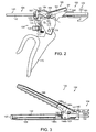
- FIG. 2 illustrates the handle of FIG. 1 in an unactuated configuration with various components removed.
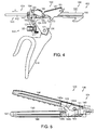
- FIG. 3 is an elevational view of an end effector of the surgical instrument of FIG. 1 illustrated in an open configuration and the distal end of a knife bar in an unadvanced position.
- FIG. 4 illustrates a trigger and a first drive system of the handle of FIG. 2 in a partially actuated configuration.
- FIG. 5 is an elevational view of the end effector of FIG. 3 illustrated in a partially closed configuration and the knife bar of FIG. 3 in a partially advanced position.
- FIG. 6 illustrates a toggle clamp of the first drive system of FIG. 4 in a completely actuated configuration.
- FIG. 7 is an elevational view of the end effector of FIG. 3 illustrated in a fully closed configuration and the knife bar in a partially advanced position.
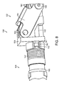
- FIG. 8 is a detail view of a yoke spring positioned intermediate a shaft of the surgical instrument of FIG. 1 and a yoke of the first drive system of FIG. 4 .
- FIG. 9 illustrates a lock system for locking and unlocking a second drive system of the handle of FIG. 2 , wherein the lock system is illustrated in an unactuated and locked configuration.
- FIG. 9 further illustrates a portion of the first drive system of FIG. 4 in an unactuated configuration.
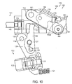
- FIG. 10 illustrates the lock system of FIG. 9 in an actuated, but locked configuration and the first drive system of FIG. 4 in an unactuated configuration.
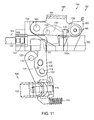
- FIG. 11 illustrates the lock system of FIG. 9 in an actuated and unlocked configuration and the first drive system of FIG. 4 in an actuated configuration.
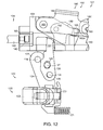
- FIG. 12 illustrates the lock system of FIG. 9 in an unactuated and locked configuration and the first drive system of FIG. 4 in an actuated configuration.
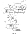
- FIG. 13 illustrates the lock system of FIG. 9 in an actuated and unlocked configuration and the first drive system of FIG. 4 in an actuated configuration.
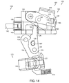
- FIG. 14 illustrates the lock system of FIG. 9 returned to a locked configuration.
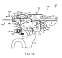
- FIG. 15 illustrates the toggle clamp of the first drive system in a completely actuated configuration and the trigger of FIG. 4 operably engaged with a second drive system.
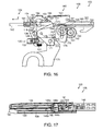
- FIG. 16 illustrates a trigger gear portion of the trigger of FIG. 4 operably engaged with a compound gear system of the second drive system.
- FIG. 17 illustrates the end effector of FIG. 3 in a fully closed position and the knife bar of FIG. 3 in a partially advanced position.
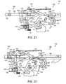
- FIG. 18 illustrates the trigger of FIG. 4 in a fully actuated position and a rack of the second drive system of FIG. 15 in a fully advanced position.
- FIG. 19 illustrates the end effector of FIG. 3 in a fully closed position and the knife bar of FIG. 3 in a fully advanced position proximal to a distal end of the end effector.
- FIG. 20 is a detail view of the distal end of the end effector of FIG. 19 .
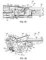
- FIG. 21 illustrates a return plate of the handle of FIG. 2 operably engaged with the trigger gear of FIG. 16 .
- FIG. 21 also illustrates the trigger of FIG. 4 and the rack of FIG. 18 in a partially retracted, or partially returned, position.
- FIG. 22 illustrates the trigger of FIG. 4 and the rack of FIG. 18 in a further partially retracted, or further partially returned, position.
- FIG. 23 illustrates the trigger of FIG. 4 engaged with the toggle clamp of FIG. 6 and the toggle clamp being moved from its fully actuated configuration to a partially actuated configuration.
- FIG. 23 also illustrates the rack of FIG. 18 in a further partially retracted, or further partially returned, position and the lock system of FIG. 9 re-engaged with the rack of FIG. 18 .
- FIG. 24 illustrates the toggle clamp of FIG. 6 in a further partially actuated configuration and the rack of FIG. 18 in a further partially retracted, or further partially returned, position.
- FIG. 25 illustrates the end effector of FIG. 3 in a partially opened position and the knife bar of FIG. 3 in a partially retracted position.
- FIG. 26 illustrates the toggle clamp of FIG. 6 in an unactuated configuration.
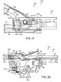
- FIG. 27 illustrates the end effector of FIG. 3 in a fully opened position and the knife bar of FIG. 3 in a fully retracted position.
- FIG. 28 illustrates the toggle clamp of FIG. 6 in an unactuated configuration and the rack of FIG. 18 in a fully retracted position.
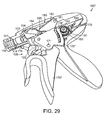
- FIG. 29 is a perspective view of a handle of an alternative embodiment of a surgical instrument in an unactuated configuration illustrated with various components removed.
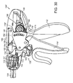
- FIG. 30 is another perspective view of the handle of FIG. 29 in a partially actuated position illustrating a trigger coming into operative engagement with a gear of a second drive system.
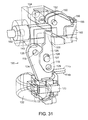
- FIG. 31 is a perspective view of the lock system of FIG. 9 in an unactuated, but locked configuration with an alternative embodiment of a rack of the second drive system.
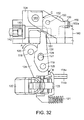
- FIG. 32 is an elevational view of the lock system of FIG. 9 in the unactuated, but locked configuration of FIG. 31 .
- FIG. 32 further illustrates a button switch of the lock system in an unactuated configuration.
- FIG. 33 illustrates the button switch of FIG. 32 in an actuated position.
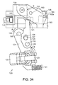
- FIG. 34 illustrates the button switch of FIG. 32 in an actuated position, a link of the lock system in an actuated position, and the lock of the lock system in an unlocked position.
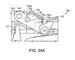
- FIG. 34A is a detail view of the lock of FIG. 34 and a lock spring configured to bias the lock into engagement with the rack.
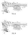
- FIG. 35 illustrates the lock system of FIG. 9 in an actuated, unlocked configuration and the rack of FIG. 31 in an unadvanced position.
- FIG. 36 illustrates the lock system of FIG. 9 in an actuated, unlocked configuration and the rack of FIG. 18 in an unadvanced position.
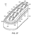
- FIG. 37 illustrates a jaw of an end effector in accordance with at least one embodiment.
- FIG. 38 illustrates a jaw of an end effector comprising steam control paths in accordance with at least one embodiment.
- FIG. 38A is a cross-sectional view of the jaw of FIG. 38 illustrating the steam control paths extending through an electrode of the end effector. Various components of the end effector have been removed in FIG. 38A .
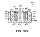
- FIG. 38B is a cross-sectional view of a jaw of an alternative embodiment of an end effector illustrating steam control paths in supply electrodes, return electrodes, insulators positioned intermediate the supply electrodes and the return electrodes, and a cutting member movable within the end effector.
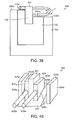
- FIG. 39 illustrates a jaw of an end effector comprising a movable electrode.
- FIG. 40 illustrates a jaw of an end effector comprising first and second insulators which are movable relative to an electrode.
- FIG. 41 illustrates a trigger assembly of an alternative embodiment of a surgical instrument, wherein the trigger assembly further comprises a mechanism for limiting the force that can be transmitted through the trigger assembly.
- FIG. 41 further illustrates a first part of the trigger assembly (illustrated with phantom lines) moved relative to a second part of the trigger assembly.
- FIG. 42 is an elevational view of the first part of the trigger assembly.
- FIG. 43 is an elevational view of the second part of the trigger assembly.
- FIG. 44 illustrates a trigger assembly of an alternative embodiment of a surgical instrument, wherein the trigger assembly further comprises a mechanism for limiting the force that can be transmitted through the trigger assembly.
- FIG. 44 further illustrates a first part of the trigger assembly (illustrated with phantom lines) moved relative to a second part of the trigger assembly.
- FIG. 45 is a diagram of an energy trigger assembly.
- FIG. 46 is a diagram of another energy trigger assembly.
- proximal and distal may be used throughout the specification with reference to a clinician manipulating one end of an instrument used to treat a patient.
- proximal refers to the portion of the instrument closest to the clinician and the term “distal” refers to the portion located furthest from the clinician.
- distal refers to the portion located furthest from the clinician.
- spatial terms such as “vertical,” “horizontal,” “up,” and “down” may be used herein with respect to the illustrated embodiments.
- surgical instruments may be used in many orientations and positions, and these terms are not intended to be limiting and absolute.
- a surgical instrument can be configured to supply energy, such as electrical energy and/or heat energy, for example, to the tissue of a patient.
- a surgical instrument such as surgical instrument 100, for example, can comprise a handle 102, a shaft 104, and an end effector 106 ( FIG. 3 ).
- the handle 102 can comprise one or more switches or triggers which can be configured to supply electrical energy to end effector 106 and/or advance a knife or cutting member within the end effector 106, for example, in order to transect the tissue positioned within the end effector 106.
- the handle 102 can comprise one or more electrical inputs, such as input, or terminal, 110, for example, which can be operably coupled with a power supply, such as a voltage supply, for example.
- a power supply such as a voltage supply, for example.
- a power supply can provide an electrical current to the surgical instrument 100, wherein the magnitude, duration, wave form, and/or frequency, for example, of the current can be sufficiently controlled or modulated to provide a desired amount of energy to the surgical instrument 100.
- power supplies are well known within the art and a more detailed description thereof is not required.
- the handle 102 can comprise a handle body 112 which, as described in greater detail below, can be configured to operably support a switch or trigger, such as trigger system 120, for example, which can be configured to electrically couple electrical input 110 with a conductor in shaft 104 such that the current supplied to input 110 can be transmitted to end effector 106.
- handle body 112 can comprise two portions which are assembled together to form handle body 112. As the reader will note, only one of the portions, or halves, is depicted in FIG. 1 , although the other portion, or half, can be a mirror image of, or at least substantially similar to, the half depicted in FIG. 1 .
- the halves of handle body 112 can be snap-fit, press-fit, adhered, and/or fastened to one another.
- the electrical conductor within the shaft 104 can comprise a wire, such as insulated wire, for example, which can extend between trigger system 120 and an electrode 130 ( FIG. 3 ) in end effector 106.
- the handle 102 can further comprise a supply wire 114 which can be electrically coupled with an electrical supply conductor (not illustrated) encased within an outer housing, or spine, 105 ( FIG. 8 ) of the shaft 104.
- the supply conductor can comprise a conductive insert, comprised of copper, for example, which is at least partially positioned within an insulative plastic jacket or sheath, for example, of the spine 105.
- the plastic jacket can be molded over the conductive insert during an injection molding process.
- the handle 102 can comprise a slip ring 116 which can be configured to electrically couple wire 114 with the supply conductor within shaft 104.
- the slip ring 116 can comprise a circular, or an at least semi-circular, contact, for example, mounted to handle body 102 which can remain in contact with a corresponding circular, or an at least semi-circular, contact mounted to shaft 104.
- Such corresponding contacts can permit relative rotational movement between shaft 104 and handle 102 and yet still provide an electrical path between wire 114 and the electrical supply conductor within shaft 104.
- the shaft 104 can further comprise another slip ring connector which, similar to the above, can maintain electrical contact between the supply conductor of shaft 104 and a supply contact 132 ( FIG. 3 ) of electrode 130.
- electrical current can flow from the electrical input 110, through supply wire 114, through the electrical conductor in shaft 104, and into the electrode 130 such that current can flow from the electrode 130 and into the tissue captured within the end effector 106.
- the end effector can further comprise one or more return electrodes and/or conductors which can comprise a return path, or circuit, for the current.
- the return path can comprise a slip ring contact operably coupled with a return electrode in the end effector 106 and a return conductor embedded within the shaft 104, for example.
- the handle 102 can further comprise a slip ring 117, for example, which can maintain the return conductor within shaft 104 in electrical contact with return wire 115.
- the return wire 115 can extend between the slip ring 117 and an electrical output, or terminal, which can, in various embodiments, be positioned adjacent to electrical input, or terminal, 110.
- an end effector 306 can comprise an electrode 330 which can extend between a proximal end of end effector 306 and a distal end 307 of end effector 306.
- the electrode 330 can comprise a first lateral portion 331 extending along a first side of jaw member 334, a second lateral portion 333 extending along a second side of jaw member 334, and a transverse intermediate portion 335 connecting the first lateral portion 331 and the second lateral portion 333.
- the first jaw member can further comprise a return electrode and/or the end effector can further comprise a second jaw member having a return electrode which can be positioned opposite the first jaw member.
- the trigger system 120 can comprise a button 122 which can be selectively actuated in order to electrically couple the electrical input 110 with supply wire 114 and/or selectively actuated in order to electrically couple the return wire 115 with the electrical output of handle 102. More particularly, in at least one embodiment, the button 122 can be movable between an undepressed, or unactuated, position in which current cannot flow to electrode 130, and a depressed, or actuated, position in which current can flow to electrode 130.
- button 122 can be used to actuate the switch 123, and/or any other suitable switch
- other energy actuation mechanisms such as toggles, levers, and/or any suitable actuators, can be used in addition to or in lieu of the above.
- the electrical current can pass through the tissue positioned against and/or surrounding the electrode 330, for example.
- the current flowing through the electrode 330 can generate heat within the electrode and the surrounding tissue.
- the heat can denature the collagen within the tissue and, in co-operation with clamping pressure provided by the jaws of the end effector, the denatured collagen can form a seal within the tissue, for example.
- the first side 331 of electrode 330 can be configured to create a first seal within the tissue and the second side 333 of electrode 330 can be configured to create a second seal within the tissue.
- one or more of the jaw members of an end effector can comprise grasping portions which can be utilized to manipulate tissue within a surgical site and/or position and hold the tissue within the end effector.
- first jaw member 334 can comprise at least one grasping member, such as a grasping portion 337, for example, which can be comprised of an electrically non-conductive, or insulative, material, such as plastic and/or ceramic, for example.
- a grasping portion 337 can hold the tissue within the end effector without conducting, or at least not significantly conducting, current and/or heat to the tissue.
- the possibility of the treated tissue adhering to, or becoming stuck to, the grasping portions 337 can be reduced or eliminated.
- each grasping portion 337 can comprise an array or row of teeth 339, for example, wherein, in at least one embodiment, a first grasping portion can comprise a first array or row of teeth 339 and a second grasping portion can comprise a second array or row of teeth 339.
- the first row of teeth 339 can be positioned adjacent to the first lateral portion 331 of electrode 330 and the second row of teeth 339 can be positioned adjacent to the second lateral portion 333 of electrode 330.
- the grasping portions 337 can be comprised of an electrically non-conductive plastic, glass, and/or ceramic, for example, and, in at least one embodiment, the grasping portions 337 can be formed by an injection molding process.
- at least one lubricant additive such as Teflon, for example, can be mixed or embedded within the plastic.
- the one or more lubricants can prevent, or at least inhibit, the tissue captured within the end effector 306 from sticking or adhering to the teeth 339, for example.
- at least one lubricant, such as Teflon for example, can be coated on the grasping portions 337.
- the grasping portions 337 can be comprised of an electrically conductive material which can be coated, or at least partially coated, with an electrically non-conductive material, for example
- At least one of the jaws, such as first jaw 434, for example, of end effector 406 can comprise at least one steam control path, passage, or conduit for conveying the steam, and/or other vapors created by the current and/or heat, away from the surgical site.
- an electrode such as electrode 430, for example, can comprise an electrode body and at least one steam control path therein.
- the steam control path can comprise one or more passages 439 which can extend longitudinally through the first lateral portion 431 and the second lateral portion 433 of electrode 430, for example.
- the steam control paths can further comprise one or more passages, or holes, 437 which can extend between an outside surface of electrode 430 and the passages 439 such that steam can flow from the tissue being treated, through the holes 437, and into the passages 439.
- the passage 439 extending though the first lateral portion 431 and the passage 439 extending through the second lateral portion 433 can be in fluid communication via a passage within intermediate portion 435 of electrode 430.
- the shaft of the surgical instrument such as shaft 104 of surgical instrument 100, for example, can comprise one or more passages or conduits therein which can be in fluid communication with the passages 439, for example, such that the heated vapors can be conveyed away from the end effector and out of the patient.
- the handle of the surgical instrument, such as handle 102 can comprise at least one vent configured to allow the heated vapors to vent into the atmosphere surrounding the patient, for example.
- a jaw 434' of an end effector 406' can comprise, similar to the above, a supply electrode 430 having first and second portions 431, 433 and steam control paths comprising passages 437, 439 extending therethrough.
- the end effector 406' can further comprise at least one return electrode 436 and one or more electrically non-conductive insulators 438 positioned intermediate portions of the supply electrode 430 and portions of the return electrode 436.
- the return electrode and/or the insulators can comprise one or more steam control paths for conveying steam away from the tissue being treated.
- the return electrode can comprise one or more channels 432 therein which can be configured to convey the steam in a space intermediate the tissue and an outside surface of the return electrode 436.
- the insulators 438 can comprise one or more passages 439' extending therethrough.
- passages 437, 439, and 439' are illustrated as comprising round, or at least substantially round, elongate configurations, the passages extending through the supply electrode, the return electrode, and/or the insulators can comprise any suitable configuration, such as square and/or rectangular configurations, for example.
- channels 432 are illustrated as having substantially orthogonal sidewalls, the sidewalls of the channels can comprise any suitable configuration, such as arcuate and/or semi-circular configurations, for example.
- any one of the supply electrode, return electrode, and/or insulators can comprise any suitable number of exterior channels and/or internal passages therein for conveying heated vapors away from the tissue in the end effector.
- a cutting member 440 can comprise one or more steam paths 439" extending therethrough.
- surgical instrument 100 can comprise a trigger system, such as trigger system 120, for example, which can be configured to prevent the cutting member 140 ( FIG.
- the cutting member 140 can be advanced at the same time that current is supplied to electrode 130. In certain other embodiments, the current can be supplied to electrode 130 prior to cutting member 140 being advanced to transect the tissue.
- the trigger system 120 can comprise an energy actuation button 122 mounted to a first link 124, a second link 126 operably coupled with first link 124, and a pivotable lock 150 which can be moved between a locked position and an unlocked position by second link 126.
- the button 122 can be moveable between an unactuated, or undepressed, position ( FIG. 32 ) and an actuated, or depressed, position ( FIG. 33 ) in order to electrically connect, or couple, a first portion 114a of supply wire 114 and a second portion 114b of supply wire 114.
- the trigger system 120 can further comprise a switch 123 mounted to first link 124 which can be switched, or closed, when button 122 is depressed such that current can flow from the electrical input 110, through the first supply wire portion 114a, and into the second supply wire portion 114b and slip ring 116. As described above, the current can then flow to electrode 130, through return wire 117, and then through the electrical outlet in order to complete the electrical circuit.
- the switch 123 can comprise a spring, such as a linear coil spring, for example, positioned therein which can be compressed when the button 122 is moved from its unactuated position to its actuated position.
- the coil spring can be positioned intermediate the button 122 and a housing of the switch 123 and/or first link 124. In any event, in certain embodiments, a force is required to compress the spring and, in addition, the button 122 is required to move a predetermined distance in order to actuate switch 123.
- the force applied to button 122 in order to actuate switch 123 can cause first link 124 to move. More particularly, the force applied to button 122 can be transmitted through the coil spring to switch 123 wherein the force can then be transferred to first link 124.
- the first link 124 can comprise a first end 125 pivotably mounted to handle body 112 via a pivot or pin 118 extending from handle body 112 and through an aperture in first end 125. When first link 124 is moved by the force, the first link 124 can rotate or pivot about an axis defined by pin 118 in a direction indicated by arrow A ( FIG. 32 ).
- the first link 124 can further comprise a drive member 127 extending therefrom which can be configured to move second link 126.
- the second link 126 can comprise a first end 129 pivotably mounted to handle body 112 via a pivot or pin 119 extending from handle body 112 and through an aperture in first end 129.
- the drive member 127 can extend into a slot 128 in second link 126 such that, when the first link 124 is rotated about pivot 118 in direction A, the second link 126 can be rotated about pivot 119 in a direction indicated by arrow B ( FIG. 32 ).
- the drive member 127 extending into slot 128 can engage a sidewall of the slot 128 so as to transmit movement between first link 124 and second link 126.
- the second link 126 can further comprise a second end 151 which can be configured to engage rack 150 and rotate rack lock 150 between an unactuated, locked position ( FIG. 33 ) and an actuated, unlocked position ( FIG. 34 ). More particularly, when second link 126 is rotated in direction B, the rack lock 150 can be rotated in a direction indicated by arrow C ( FIG. 32 ) about an axis defined by pivot 152 on yoke 154. When rack lock 150 is sufficiently rotated in direction C, as described in greater detail further below, tooth 155 extending from rack lock 150 may be sufficiently removed from notch 162a in rack 160 such that rack 160 can be moved relative to lock 150.
- the force applied to button 122 in order to actuate switch 123 can rotate first link 124 about pivot 118, rotate second link 126 about pivot 119, and rotate rack lock 150 between locked and unlocked positions.
- a force can be sufficient to actuate switch 123 and unlock rack 150 at the same time, or at least substantially the same time.
- energy can be supplied to the electrode 130 at the same time that rack 160 becomes unlocked and capable of advancing knife bar 140 distally within end effector 106 as described in greater detail below.
- the trigger system 120 can assure that the tissue positioned within the end effector is not transected before it is at least partially treated and/or sealed.
- the trigger system 120 can further comprise a trigger spring 121 operably engaged with the first link 124, for example, which can be configured to resist the movement of first link 124 in the direction indicated by arrow A.
- the force applied to button 122 to actuate switch 123 may be insufficient to rotate first link 124 and second link 126 a sufficient distance to move rack lock 150 into its unlocked position.
- the switch 123 can be actuated to supply electrode 130 with current while the rack 160 can remain locked in place by rack lock 150. More particularly, further to the above, the tooth 155 of rack lock 150 can remain biased into first notch 162a by lock spring 156 such that rack 160 is prevented from moving, or at least substantially moving, relative to rack lock 150.
- a rack lock may be slid between a first position in which it is locked with a rack, such as rack 160, for example, and a second position in which it is unlocked from the rack.
- the rack lock can be moved along a straight line.
- a larger, or second, force may need to be applied to button 122 and/or first link 124. More particularly, in the event that the force, or first force, used to depress button 122 and actuate switch 123 is insufficient to unlock rack lock 150, a second, or larger, force can be applied to button 122, for example, in order to sufficiently compress spring 121, sufficiently rotate first link 124 and second link 126, and rotate rack lock 150 into an unlocked position. In such circumstances, a clinician may apply a light force to button 122 in order to actuate the electrical energy system and a heavier force to button 122 in order to unlock the rack 160. In various embodiments, referring to FIG.
- trigger spring 121 can be positioned intermediate first link 124 and handle body 112 such that trigger spring 121 is compressed as first link 124 is rotated in the direction indicated by arrow A.
- the length and/or stiffness of trigger spring 121 can be selected such that the coil spring within switch 123 is sufficiently compressed to supply electrode 130 with electrical energy before the trigger spring 121 is sufficiently compressed to unlock rack 160.
- the treatment or sealing of the tissue positioned within the end effector 106 can begin before rack 160 and cutting member 140 can be advanced.
- the difference between the first force and the second force can be large enough such that a surgeon, or other clinician, using the surgical instrument 100 may be provided with a tactile feedback as to whether the surgical instrument is in a first operating condition in which energy is being applied to the tissue and the cutting member is not being advanced within the end effector and a second operating condition in which energy is being applied to the tissue and the cutting member is being advanced within the end effector to transect the tissue.
- the switch spring and the trigger spring 121 can be selected such that a significantly smaller force is required to depress button 122 and actuate switch 123 as compared to a significantly larger force required to unlock rack lock 150.
- the stiffness of the spring in switch 123 and the stiffness of trigger spring 121 can be selected such that a force which is sufficient to actuate button 122 can also be sufficient to rotate lock 150 into an unlocked configuration.
- the force necessary to actuate button 122 can be the same, or at least substantially the same, as the force necessary to unlock rack 160.
- the surgeon can release button 122 such that the spring of switch 123 can return button 122 to an unactuated position and operably disconnect first portion 114a and second portion 114b of supply wire 114.
- electrical current may no longer flow to electrode 130 and, as a result, the electrode 130 and the tissue within the end effector may begin to cool.
- the trigger spring 121 may return first link 124 and/or second link 126 to their unactuated positions and the lock spring 156 may return rack lock 150 to an unlocked position. More particularly, referring now to FIG.
- the lock spring 156 can reposition the lock tooth 155 within the notch 162a and relock the rack 160 in position.
- the rack 160 may be sufficiently advanced such that the rack tooth 155 cannot be reseated within the notch 162a and, as a result, the lock spring 156 may position the tooth 155 against a top surface 161 of rack 160 in an unlocked position. In such circumstances, the rack 160 and the cutting member 140 can be advanced within the tissue without current flowing to the electrode 130.
- a rack 160' can comprise a plurality of notches 162a-162e, for example, which can, once the button 122 has been released, allow the lock spring 156 to return the lock 150 to a locked configuration even though the rack 160' and the cutting member 140 have already been advanced. More particularly, depending on the distance that rack 160 has been advanced, the lock spring 156 can position the lock tooth 155 in any one of the notches 162b-162e, for example.
- the surgeon may keep the button 122 depressed and the first link 124 and the second link 126 sufficiently rotated in order to keep the lock 150 in an unlocked position. In such circumstances, owing to the constant depression of button 122, electrical energy can be supplied to the electrode 130 during the entire, or at least substantially entire, advancement of rack 160 and cutting member 140.
- lock spring 156 can be configured to bias lock 150 into engagement with rack 160.
- lock spring 156 can comprise a torsion spring including a coil 156a positioned about pivot pin 152, a first end extending from coil 156a mounted to yoke 154, and a second end 156b.
- the second end 156b can comprise a torque arm which, when the lock 150 is rotated about pivot pin 152 as described above, the second end 156b can torque or compress the spring coil 156a.
- the spring 156 can store potential energy therein which, when released, can act to move lock 150 from its unlocked position into its locked position.
- the second end 156b can comprise a hook or attachment portion 156c which can mount the second end 156b to lock 150 such that the second end 156b moves the lock 150.
- the distance to move button 122 from an unactuated position to an actuated position can be shorter than the distance to rotate link 124 sufficiently to move lock 150 between a locked position and an unlocked position.
- the actuation of button 122 although it may cause first link 124 and second link 126 to rotate, may be insufficient to rotate first link 124 and second link 126 a sufficient distance to move lock 150 into its unlocked configuration.
- the button 122 can be depressed to supply electrical energy to the electrode 130 while the rack 160, for example, can remain locked in position by rack lock 150.
- the tissue can be sealed, or at least partially sealed, before the cutting member 140 is advanced through the tissue within the end effector 106.
- the button 122 and the first link 124 can be moved an additional distance in order to sufficiently rotate lock 150 into an unlocked configuration such that rack 160 and cutting member 140 can be advanced into and/or through the tissue.
- the button 122 can be moved a first distance to supply electrical current to electrode 130 although the button 122 can be moved a total distance which is greater than the first distance to unlock rack lock 150.
- the difference between the first distance and the total distance that button 122 is moved can be sufficient to provide a sufficiently large window of operation to allow the surgeon to move button 122 within a range of distances while not unlocking the rack lock 150.
- the distance necessary to actuate button 122 may the same, or at least substantially the same, as the distance necessary to move lock 150 between its locked and unlocked configurations.
- rack 160 and cutting member 140 can be advanced toward distal end 107 ( FIG. 3 ) of end effector 106.
- the advancement of cutting member 140 can, one, move jaw 108 toward jaw 109 and, two, incise the tissue captured between jaw 108 and jaw 109.
- the handle 102 can further comprise a trigger 170 which can be moved between an unactuated position, as illustrated in FIG. 1 , and an actuated position, as illustrated in FIG. 18 .
- the movement of trigger 170 between its actuated position and unactuated position can define one stroke of trigger 170, although such a stroke can comprise two different ranges of motion.
- the stroke can comprise a first range of motion which drives a first drive system and a second range of motion which drives a second drive system.
- the trigger 170 in co-operation with the first drive system, can advance the rack 160 and the cutting member 140 between a first position ( FIG. 3 ) and a second position ( FIG. 7 ) during the first range of motion of trigger 170, wherein the trigger 170, in co-operation with the second drive system, can advance the rack 160 and the cutting member 140 between a second position ( FIG. 7 ) and a third position ( FIG. 19 ) during the second range of motion of trigger 170.
- the cutting member 140 is moved between its first position ( FIG. 3 ) and its second position ( FIG.
- the cutting member 140 can move the second jaw 108 toward the first jaw 109 and clamp tissue positioned therebetween.
- the cutting member 140 can be advanced toward the distal end 107 to incise the tissue clamped between jaw 108 and jaw 109.
- the first drive system can comprise a toggle clamp 180 which can be moved between a first configuration ( FIG. 2 ) associated with the first position ( FIG. 3 ) of cutting member 140 and a second configuration ( FIG. 6 ) associated with the second position ( FIG. 7 ) of cutting member 140.
- the toggle clamp 180 can comprise a first link 182 and a second link 184.
- the first link 182 can comprise a first end pivotably mounted to handle body 112 at first pivot 181, via a pivot pin, for example
- the second link 184 can comprise a first end pivotably mounted to yoke 154 at a second pivot 183, also via a pivot pin, for example.
- first link 182 and the second link 184 can each comprise second ends which are pivotably mounted to each other via an intermediate pivot pin 185, for example.
- the intermediate pivot pin 185 can comprise a vertex of an angle defined between a first line, or axis, 186 extending through the centers of first pivot 181 and intermediate pivot 185 and a second line, or axis, 187 extending through the centers of second pivot 183 and intermediate pivot 185.
- the first line 186 and the second line 187 can define a vertex angle ⁇ therebetween.
- Opposite vertex angle ⁇ is a line, or axis, 188 defined between the center of first pivot 181 and the center of second pivot 183.
- the vertex angle ⁇ can be about 90 degrees and/or slightly greater than 90 degrees, for example. In at least one embodiment, angle ⁇ can be about 120 degrees when toggle clamp 180 is in its first configuration, for example. Although such angles may be suitable in various circumstances, any other suitable angle can be used.
- the trigger 170 can be moved from its unactuated position ( FIG. 2 ) into a partially actuated position ( FIG. 4 ) as part of its first range of motion.
- trigger 170 is pivotably mounted to handle body 112 via a pivot 171, such as a pivot pin, for example.
- trigger 170 can begin to move the toggle clamp 180 from its first configuration ( FIG. 2 ) into its second configuration ( FIG. 6 ).
- the trigger 170 can further comprise a cam, or driver, 172 extending therefrom which can be configured to engage first link 182 and lift the second end of link 182 upwardly and, at the same time, rotate first link 182 about first pivot 181 in a direction indicated by arrow D ( FIG. 4 ).
- a cam, or driver, 172 extending therefrom which can be configured to engage first link 182 and lift the second end of link 182 upwardly and, at the same time, rotate first link 182 about first pivot 181 in a direction indicated by arrow D ( FIG. 4 ).
- the upward movement of the second end of first link 182 can cause the second end of second link 184 to move upwardly and, at the same time, rotate about second pivot 183 in a direction indicated by arrow E ( FIG. 4 ).
- first link 182 can comprise a cam, or drive, pocket 173 which can be engaged by cam, or driver, 172 in order to transmit the rotation of trigger 170 to first link 182.
- the yoke 154 can translate distally in a direction indicated by arrow F ( FIG. 4 ).
- the distal movement of yoke 154 in the direction F can be transmitted to rack 160 and cutting member 140 such that rack 160 and cutting member 140 are also moved in direction F.
- the rack lock 150 mounted to yoke 154 when engaged with rack 160, can allow the yoke 154 to pull the rack 160 distally when the yoke 154 is pushed distally by toggle clamp 180 as described above.
- the distal movement of rack 160 can be transmitted to cutting member 140.
- the cutting member 140 can comprise a proximal portion 142 which can be connected to the distal end 165 of rack 160.
- such a connection can prevent, or at least inhibit, relative longitudinal movement between cutting member proximal end 142 and rack distal end 165 while permitting relative rotational movement therebetween owing to a round head 143 of the proximal end 142 captured within a round cavity in the distal end 165 of rack 160.
- the proximal movement of cutting member 140 can, in at least one embodiment, cause cutting member 140 to engage the second jaw 108 and move, or rotate, second jaw 108 toward first jaw 109.
- the cutting member 140 can comprise one or more cams, or cam pins, 144a which can be configured to engage one or more cam surfaces 145 on second jaw 108 and rotate second jaw 108 downwardly about one or more pivot pins 103, for example.
- the rotation of trigger 170 through its first range of motion can move the toggle clamp 180 between its first, or unactuated, configuration ( FIG. 2 ) and its second, or fully actuated, configuration ( FIG. 6 ).
- the movement of the toggle clamp 180 between its first configuration and its second configuration can move the cutting member 140 between its first position ( FIG. 3 ) and its second position ( FIG. 7 ) and, as a result, move second jaw 108 between its fully open position ( FIG. 3 ) and its fully closed position ( FIG. 7 ).
- the vertex angle ⁇ defined between first line 186 and second line 187 is about 180 degrees, for example.
- the vertex angle ⁇ can be about 175 degrees, for example.
- the toggle clamp 180 can transmit a very large longitudinal force to rack 160 and cutting member 140 in the distal direction F.
- this very large longitudinal force can increase exponentially and/or asymptotically as the vertex angle ⁇ approaches approximately 180 degrees.
- This very large longitudinal force can apply a large biasing force to second jaw 108 such that a large clamping force, or pressure, is applied to the tissue positioned intermediate the first jaw 109 and the second jaw 108.
- the distal movement of yoke 154 can compress a yoke spring, such as axial spring 147, for example, intermediate yoke 154 and a spine 105 of shaft 104.
- a yoke spring such as axial spring 147
- the axial spring 147 can store potential energy therein which can be released in order to at least partially retract rack 160 and cutting member 140.
- the toggle clamp 180 is illustrated in its first, or unactuated configuration, in FIG. 8 , the axial spring 147 is at least partially compressed between shaft spine 105 and yoke 154.
- the compression force applied to shaft spine 105 and yoke 154 by spring 147 can provide an additional benefit of inhibiting relative movement between shaft spine 105 and yoke 154.
- FIG. 9 which illustrates the toggle clamp 180 in its first configuration and the trigger assembly 120 in its unactuated configuration
- the rack lock 150 is in its locked position and rack 160 is in its unadvanced position.
- the trigger assembly 120 can be actuated so as to rotate first link 124 about pivot 118 and rotate second link 126 about pivot 119; however, in circumstances where the rack 160 and cutting member have not yet been advanced into their second positions, for example, the actuation of trigger assembly 120 may not move rack lock 150 into its unlocked position.
- rack 160 and cutting member 140 Upon the advancement of rack 160 and cutting member 140 into their second positions, referring now to FIG.
- the rack lock 150 can be moved into contact with second link 126 such that rack lock 150 is rotated from its locked position to its unlocked position.
- the rack 160 and cutting member 140 can be advanced from their first positions ( FIG. 9 ) to their second positions ( FIG. 12 ) when the toggle clamp 180 is moved from its first configuration into its second configuration, as described above, and wherein, upon a sufficient actuation of trigger assembly 120, as described above, the second link 126 can contact rack lock 150 and rotate rack lock 150 into its unlocked configuration as illustrated in FIG. 13 .
- trigger 170 upon the completion of its first range of motion, become operably disengaged from the first drive system and/or operably engaged with the second drive system.
- FIG. 15 depicts the trigger 170 at the end of its first range of motion
- the cam 172 is no longer positioned within pocket 173 in first link 182.
- the cam 172 may no longer drive the toggle clamp 180 despite any further rotation of trigger 170 toward its actuated position ( FIG. 18 ), and, as a result, the trigger 170 may be operably disconnected from the first drive system.
- the trigger 170 has been moved into operative engagement with trigger gear 175 and the second drive system. More particularly, referring now to FIG.
- the trigger 170 can further comprise a drive pin 176 extending therefrom which is configured to contact the bottom surface 177 of trigger gear 175 and, once engaged with trigger gear 175, push, or rotate, the trigger gear 175 upwardly such that the trigger gear 175 rotates a compounding gear 191 of the rack and pinion system 190 as trigger 170 is moved through its second range of motion.
- the trigger gear 175 comprises an array of teeth 178 which are operably engaged with, or meshed with, the compounding gear 191 while the trigger 170 is moved through its first range of motion, although, the teeth 178 do not drive the compounding gear 191 during the first range of motion of trigger 170.
- the rotation of trigger 170 in its second range of motion can cause trigger gear 175 to drive or rotate compounding gear 191 as described in greater detail further below.
- the disengagement of cam 172 from pocket 173 in first link 182 can occur at the same time, or at least substantially the same time, as the trigger 170 comes into operative engagement with trigger gear 175.
- the trigger 170 may not come into operative engagement with trigger gear 175 until after the cam 172 has been disengaged from pocket 173.
- the rotation of trigger 170 may comprise a dwell period in which the trigger 170 is not operatively engaged with either the first drive system of the second drive system.
- the further rotation of trigger 170 can, one, cause the cam 172 to move relative to a bottom surface 187 of first link 182, and, two, rotate compounding gear 191.
- the compounding gear 191 can be mounted to a pin 192 which can be rotatably mounted between the two halves of handle body 112.
- the rack and pinion system 190 can further comprise an additional, or second, compounding gear 193 which can be mounted to pin 192.
- the compounding gears 191, 193 can be mounted to pin 192 such that the rotation of one of compounding gears 191, 193 causes the rotation of the other of the compounding gears 191, 193.
- the rack and pinion system 190 can further comprise a third compounding gear 195 which can be mounted to a pin 194 which can be rotatably mounted between the two halves of handle body 112. As illustrated in FIG. 16 , the third compounding gear 195 can be operably meshed with the second compounding gear 193 such that the rotation of second compounding gear 193 can rotate the third compounding gear 195.
- the rack and pinion system 190 can further comprise a pinion gear 197 which can also be mounted to pin 194, wherein, similar to the above, the compounding gear 195 and the pinion gear 197 can be mounted to pin 194 such that the rotation of one of gears 195, 197 causes the rotation of the other of the gears 195, 197.
- the pinion gear 197 is operably or meshingly engaged with the rack teeth 164 on rack 160 such that the rotation of pinion gear 197 can move, or displace, rack 160 along a straight, or at least substantially straight, path, for example.
- the rotation of trigger 170 can be transmitted to pinion gear 197 via compounding gears 191, 193, and 195 such that, owing to the gear ratio of gears 191, 193, 195, and 197, a small rotation of trigger 170 can result in a large displacement of rack 160 and cutting member 140.
- the rotation of trigger 170 through its second range of motion can move cutting member 140 between its second position ( FIG. 17 ) and its third position ( FIG. 19 ). In its second position, referring to FIG.
- the cutting member 140 can be positioned within the end effector 106 such that the knife edge 146 of cutting member 140 is positioned to be advanced through the tissue captured between first jaw 109 and second jaw 108, and owing to the rotation of trigger 170, trigger gear 175, and gears 191, 193, 195, and 197, the rack 160 can be displaced in the distal direction F so as to displace the cutting member 140 toward the distal end 107 of end effector 106.
- the cutting member 140 In its third position, referring to FIGS. 18 and 19 , the cutting member 140 can be positioned at the distal end 107 of end effector 106. In at least one embodiment, referring to FIG.
- jaw 108 and/or jaw 109 can comprise a slot 149 which can be configured to receive at least a portion of cutting member 140 and guide cutting member 140 toward the distal end 107.
- the cam pins 144a extending from cutting member 140 can be configured to ride on top of cam surface 148a on the outside of jaw 108 such that jaw 108 is compressed toward jaw 109.
- cutting member 140 can further comprise cam pins 144b extending therefrom which can be configured to ride on cam surface 148b on the outside of jaw 109 such that jaw 109 is compressed toward jaw 108.
- jaw 108 and/or jaw 109 can further comprise a stop 147 which can be configured to stop the distal displacement of cutting member 140 through the tissue.
- the stop 147 can be positioned proximally with respect to the distal end of electrode 130 such that the knife edge 146 may not transect tissue which has not been sealed.
- a return spring such as torsion spring 199 ( FIG. 28 ), for example, can reverse the rotation of compounding gears 191, 193, and 195 and pinion gear 197 in order to retract rack 160 and cutting member 140 in a proximal direction, i.e., in a direction opposite direction F.
- torsion spring 199 FIG. 28
- one end of the torsion spring 199 can be engaged with the compounding gear 191 and another end of the torsion spring 199 can be engaged with the handle body 112, for example, such that potential energy stored within the torsion spring 199 when the rack 160 is advanced can be released when the trigger 170 is released in order to rotate compounding gear 191 in a reverse direction.
- the reverse rotation of compounding gear 191 can, owing to the meshing engagement of trigger gear teeth 178 and compounding gear 191, rotate trigger gear 175 downwardly in a direction indicated by arrow G.
- the downward rotation of trigger gear 175 can be transmitted to trigger 170 via the interaction of drive surface 177 acting against the drive pin 176 in order to retract, or return, the trigger 170 through its second range of motion, as illustrated in FIG. 22 .
- the surgical instrument can further comprise a reversing plate 200 which can be operably engaged with compounding gear 191 such that the reverse rotation of compounding gear 191 can also be transmitted to trigger gear 175 via reversing plate 200.
- the reversing plate 200 can be keyed to compounding gear 191 and/or pin 192 such that, as compounding gear 191 is driven in a reverse direction by return spring 199, the reversing plate 200 is driven downwardly and rotated about an axis defined by pin 192 in a direction indicated by arrow H. In such circumstances, referring to FIG. 22 , the reversing plate 200 can act against drive pin 202 extending from trigger gear 175 to drive trigger gear 175 downwardly.
- the return spring 199 via gears 191, 193, 195, and 197, can return the cutting member 140 and the rack 160 from their third position to their second position and allow the rack lock 150 to re-engage the rack 160 as illustrated in FIG. 23 .
- the yoke spring 147 Owing to the re-engagement of rack lock 150 with rack 160, the yoke spring 147 can push yoke 154, rack 160, and cutting member 140 in a proximal direction, i.e., a direction opposite direction F.
- the yoke spring 147 via yoke 154, can move the rack 160 and the cutting member 140 from their second positions to their first positions.
- the cutting member 140 can move second jaw 109 from its closed position to its open position. More particularly, in at least one embodiment, the cutting member 140 can further comprise at least one opening cam pin 141 extending therefrom which, when moved proximally, can engage cam surface 101 a on second jaw 109 such that second jaw 109 is pivoted upwardly about pivot pins 103 into its open position as illustrated in FIG. 27 . Once jaw 109 has been moved into its open position, the cam pin 141 can be further retracted such that it is positioned over and/or against lock surface 101 b which is positioned proximally with respect to cam surface 101a.
- the second jaw 109 can be locked or held in an open position by cam pin 141.
- the drive pin 176 extending from trigger 170 can engage the sidewall of a slot 204 in reversing plate 200 as trigger 170 is returned to its unactuated position. More particularly, the drive pin 176 can assure that the reversing plate 200, the compounding gears 191, 193, 195, and 197, and the rack 160 have been returned to their initial positions and, as a result, assure that cutting member 140 has been returned to its initial position.
- the trigger 170 comprises a drive pin 176 which, at the end of the first range of motion of trigger 170, can contact the drive surface 177 of trigger gear 175 in order to move trigger gear 175 upwardly.
- the trigger 170 and trigger gear 175 move together about a common axis of rotation defined by pivot 171.
- the trigger 170 and trigger gear 175 can, referring to FIGS. 21-24 , for example, move independently of one another and rotate relative to one another. More particularly, the trigger 170 and trigger gear 175 can move relative to one another about a pivot 179 on trigger 170 as trigger 170 is returned to its unactuated position and as the surgical instrument 100 is reset to its initial configuration.
- an alternative surgical instrument can comprise substantially the same components and systems as surgical instrument 100, although the alternative surgical instrument can comprise a trigger assembly 170' comprising a first portion 170a' and a second portion 170b'. In certain embodiments, relative movement between the first portion 170a' and the second portion 170b' is possible during the actuation of trigger 170'.
- a force overload mechanism can be positioned intermediate the first trigger portion 170a' and the second trigger portion 170b' such that, when the force applied to trigger portion 170a' exceeds a predetermined value, the trigger portion 170a' can move relative to the trigger portion 170b' and prevent any force in excess of the predetermined value from being transmitted to trigger gear 175 via drive pin 176'.
- the first trigger portion 170a' can comprise a pivot hole 171a' which can be aligned with, referring to FIG. 43 , a pivot hole 171b' in second trigger portion 170b' wherein, when the first portion 170a' and the second portion 170b' are assembled together, as illustrated in FIG.
- first portion 170a' and the second portion 170b' can rotate together about an axis defined by pivot 171'. More particularly, a force, or load, FA applied to first portion 170a' can cause first portion 170a' to rotate about pivot 171' and, owing to drive pin 176', the rotation of first portion 170a' can be transmitted to second portion 170b' in order to cause second portion 170b' to be rotated about pivot 171'.
- a force, or load, FA applied to first portion 170a' can cause first portion 170a' to rotate about pivot 171' and, owing to drive pin 176', the rotation of first portion 170a' can be transmitted to second portion 170b' in order to cause second portion 170b' to be rotated about pivot 171'.
- the drive pin 176' can be slidably positioned within a slot 212' within first portion 170a', wherein the first portion 170a' can further comprise a spring, such as an axial compression 216', for example, configured to bias the drive pin 176' against the end 214' of slot 212'.
- the drive pin 176' can extend through a drive aperture 218' in second portion 170b', wherein, in various circumstances, at least a portion of the force FA applied to first trigger portion 170a' can be transmitted through the spring 216', drive pin 176', and a sidewall of drive aperture 218' in order to apply a force to second trigger portion 170b'.
- the force transmitted between the first trigger portion 170a' and the second trigger portion 170b' can be represented by a force FT ( FIG. 41 ) which is transmitted through spring 216.
- the force FT can be aligned, or collinear, with the longitudinal, or axial, axis of spring 216'.
- the force FT is at or below the predetermined, or threshold, value described above, the first portion 170a' and the second portion 170b' can move together with little, if any, relative movement therebetween.
- the spring 216' can be compressed between the drive pin 176' and a second sidewall 215' of the slot 212 such that the spring 216' is compressed by a preload force which is equal to, or at least substantially equal to, the predetermined threshold value. In such circumstances, the spring 216' may not be further compressed unless and if the force FT exceeds the predetermined threshold value. Once the force FT exceeds the predetermined threshold value, the spring 216' may be further compressed, thereby permitting relative movement between first portion 170a' and second portion 170b'. Furthermore, owing to such relative movement, the force in excess of the predetermined threshold value may be absorbed by the spring 216' instead of being transmitted to trigger gear 175 via drive pin 176'. Such embodiments can prevent an excessive force from being applied to rack 160 and cutting member 140 and, as a result, an overload condition can be avoided, or at least partially ameliorated.
- an alternative surgical instrument can comprise substantially the same components and systems as surgical instrument 100, although the alternative surgical instrument can comprise a trigger assembly 170"' comprising a first portion 170a"' and a second portion 170b"'. In certain embodiments, relative movement between the first portion 170a"' and the second portion 170b"' is possible during the actuation of trigger 170"'.
- a force overload mechanism can be positioned intermediate the first trigger portion 170a"' and the second trigger portion 170b"' such that, when the force applied to trigger portion 170a"' exceeds a predetermined value, the trigger portion 170a"' can move relative to the trigger portion 170b"' and prevent any force in excess of the predetermined value from being transmitted to trigger gear 175 via drive pin 176"'.
- first trigger portion 170a"' and the second trigger portion 170b"' can be pivotable about pivot pin 171"', wherein a force, or load, FA applied to first portion 170a”' can cause first portion 170a" to rotate about pivot 171"' and, owing to beam, or link, 216"', the rotation of first portion 170a"' can be transmitted to second portion 170b"' in order to cause second portion 170b"' to be rotated about pivot 171"'.
- a first end 217"' of beam 216"' can be fixedly mounted to first trigger portion 170a"' and a second end 218"' of bean 216"' can be fixedly mounted to second trigger portion 170b"', wherein, in various circumstances, at least a portion of the force FA applied to first trigger portion 170a"' can be transmitted through the beam 216"' in order to apply a force to second trigger portion 170b"'.
- the first portion 170a" and the second portion 170b" can move together with little, if any, relative movement therebetween.
- the beam 216" can be configured such that, although the below-threshold force transmitted through beam 216" may create a compressive contraction or other minor elastic deformation within the beam 216", the beam 216" will remain largely undeflected as long as the force transmitted therethrough is below the threshold value. Once the force transmitted through beam 216" exceeds the predetermined threshold value, however, the beam 216' may buckle, thereby permitting relative movement between first portion 170a' and second portion 170b'. Such relative movement is depicted in FIG.
- the various embodiments described above can prevent an excessive force from being applied to rack 160 and cutting member 140 and, as a result, an overload condition can be avoided, or at least partially ameliorated.
- an alternative surgical instrument 100" can comprise a one piece trigger 170" which can drive the first drive system and the second drive system described above. More particularly, in at least one embodiment, the trigger 170" can be, similar to the above, configured to be rotated between an actuated position and an unactuated position about pivot 171 during a stroke of trigger 170". Also similar to the above, this stroke of trigger 170" can comprise a first range of motion for driving the first drive system and a second range of motion for driving the second drive system. Referring to FIG.
- the trigger 170" is illustrated in an unactuated position wherein trigger gear teeth 178" are not operably engaged with compounding gear 191 and the toggle clamp 180 is in its first, or unactuated, configuration.
- the trigger 170" can move the toggle clamp 180 from its first configuration into its second configuration, similar to the above, and, in addition, operably engage trigger gear teeth 178" with compounding gear 191.
- the trigger 170" can rotate compounding gear 191 to advance rack 160 and cutting member 140 and, as trigger 170" is no longer operably engaged with toggle clamp 180, the trigger 170” can move relative to first link 182.
- the surgical instrument 100" can comprise a spring which can bias toggle clamp 180 back into its first configuration and return trigger 170" to its unactuated position.
- the surgical instrument 100" can further comprise a second spring which can reverse the rotation of compounding gear 191 to return the rack 160 and cutting member 140 to their initial, or starting, positions.
- the trigger 170" can further comprise a return tooth 178" which can be configured to engage compounding gear 191 and assure that compounding gear 191, rack 160, and cutting member 140 are returned to their initial, or starting, positions as trigger 170" is moved into its unactuated position as illustrated in FIG. 29 .
- the trigger assembly 120 can comprise a button 122 for actuating switch 123, wherein switch 123 is mounted to first link 124, wherein first link 124 is operably engaged with second link 126, and wherein second link 126 is configured to rotate lock 150.
- a surgical instrument can comprise a trigger assembly 720 comprising, similar to the above, a switch 723 mounted to a link 724, wherein the switch 723 can comprise a button 722 configured to actuate switch 723.
- button 722 and switch 723 can operate in substantially the same manner as button 122 and switch 123; however, in at least one embodiment, the link 724 of trigger assembly 720 may be configured such that it can engage lock 750 directly, i.e., without the presence of a second link, such as second link 126, for example, operably positioned therebetween.
- a force F can be applied to button 722 in order to actuate the switch 723 and, simultaneously, rotate link 724 about pivot 718 in a direction indicated by arrow Z.
- a drive end 751 of the link 724 can contact lock 750 and rotate lock 750 about pivot pin 752 of yoke 754 in a direction indicated by arrow Y.
- the force sufficient to actuate switch 723 may be sufficient to move lock 750 from its locked position ( FIG. 45 ), in which lock tooth 755 is positioned within recess 762 in rack 760, into an unlocked position in which rack 760 can move relative to lock 750 and yoke 754.
- the stiffness of a spring within switch 723 and the stiffness of spring 721, positioned intermediate link 724 and handle frame 712 can be selected such that switch 723 is actuated at the same time, or at least substantially the same time, as rack 760 is unlocked.
- the stiffness of spring 721 and the spring of switch 723 can be selected such that switch 723 can be actuated without moving lock 750 into an unlocked configuration.
- a second, or larger, force could be applied to button 722 in order to unlock lock 750.
- the lock can include a lock spring configured to bias the lock 750 into a locked configuration and, in at least one embodiment, the lock spring can be used in lieu of spring 721, for example.
- a surgical instrument can comprise a trigger assembly 820 comprising, similar to the above, a switch 823 comprising a button 822, wherein the switch 823 is mounted to a first link 824, and wherein upon an application of a force F to button 820, the force can rotate link 824 about pivot 818 in a direction indicated by arrow X.
- the trigger assembly 820 can further comprise a slider 826 which is operably engaged with first link 824 such that, as link 824 is rotated in direction X, link 824 can drive slider 826 upwardly in a direction indicated by arrow W within a slot defined by handle portion 812.
- the trigger assembly 820 can further comprise a lock spring 856 positioned intermediate the lock 850, for example, and the handle frame 812 wherein the lock spring 856 can be configured to bias lock 850 into recess 862.
- the switch 823 can comprise a spring wherein the stiffness of the switch spring and the lock spring 856 can be selected such that the force sufficient to actuate switch 823 can be sufficient to move lock 850 into an unlocked position and, as a result, unlock rack 860.
- the spring of switch 823 and lock spring 856 can be selected such that switch 823 can be actuated without moving lock 850 into an unlocked position.
- a second, or larger, force could be applied to button 822 in order to unlock lock 850.
- the end effector 106 of surgical instrument 100 can comprise an electrode 130 which, in co-operation with a ground or return electrode, can allow current to flow through tissue positioned within the end effector 106.
- the current flowing through the electrode 130 can generate heat within the electrode 130 in order to seal the tissue, for example.
- the electrode 130 can be securely positioned within the first jaw 108, for example, such that the electrode 130 does not move relative to the first jaw 108.
- the jaw 108 can comprise one or more insulators positioned intermediate the electrode 130 and the return electrode, wherein the insulators can assure that current does not flow directly between the electrode 130 and the return electrode without at least first passing through the tissue.
- an alternative surgical instrument can comprise an electrode 530 which can be moved relative to an insulator 532 and/or a return 534, for example.
- the electrode 530 can comprise a top surface, or tissue-contacting surface, 531 which can be configured to be positioned against the tissue T positioned within the end effector 506.
- the top surface 531 of electrode 530 can be raised and/or lowered with respect to the insulator 532 and/or return 534. More particularly, in at least one such embodiment, the top surface 531 of electrode 530 can be moved relative to the top surfaces 533a and 533b of insulator 532 and/or relative to the top surfaces 535a and 535b of return 534.
- raising the electrode 530, or top surface 531, relative to the insulator 532 and/or return 534 can increase the amount of tissue exposed to the electrode 530.
- the size of the seal created within the tissue can be increased as compared to when the electrode 530 is in a lower position, for example.
- the size of the seal created within the tissue can be decreased as compared to when the electrode 530 is in a raised position, for example.
- the electrode 530 when the electrode 530 is in a lower position, the lateral spread of heat to tissue adjacent the end effector 506 can be reduced as compared to when the electrode 530 is in a raised position.
- a surgical instrument can comprise means for lifting and/or lowering electrode 530 relative to insulator 532.
- the electrode 530 can comprise a bottom surface comprising a ramp or inclined surface, wherein, when the electrode 530 is slid longitudinally within the end effector 506, the inclined surface can contact a cam within the end effector 506 such that the electrode 530 is lifted upwardly, i.e., in a direction which is orthogonal, or at least substantially orthogonal, to a plane defined by one of top surfaces 531, 533a, 533b, 535a, and/or 535b, for example.
- the electrode 530 can be lowered downwardly relative to the plane when the electrode 530 is slid or pulled down the cam.
- the end effector 506 can comprise two or more electrodes which can be raised and/or lowered together or independently.
- the surgical instrument can comprise an actuator which moves the electrodes longitudinally within the end effector at the same time.
- the surgical instrument can comprise two or more actuators which can be actuated independently in order to independently move the electrodes.
- a surgical instrument can comprise one or more drivers comprising an inclined surface which are slid under the electrodes in a longitudinal direction and, depending on the direction the drivers are slid, the drivers can raise or lower the electrodes.
- an end effector 606 can comprise an electrode 630, a first insulator 632a positioned on a first side of electrode 630, a second insulator 632b positioned on a second side of electrode 630, a first return 634a positioned adjacent to first insulator 632a, and a second return 634b positioned adjacent to second insulator 632b.
- the end effector 606 can further comprise a first actuator 636a operably coupled to first insulator 632a, wherein the first actuator 636a can be configured to slide first insulator 632a up and/or down ramp, or cam, 637.
- the end effector 606 can further comprise a second actuator 636b operably coupled to second insulator 632b, wherein the second actuator 636b can be configured to slide second insulator 632b up and/or down ramp, or cam, 637.
- the second insulator 632b can comprise an inclined bottom surface 638b which can co-operate with the inclined surface of cam 673 in order to move top surface 633b of second insulator 632b relative to the top surface 631 of electrode 630 and/or the top surface 635b of return 634b, for example.
- first insulator 632a can comprise an inclined bottom surface which can co-operate with the inclined surface of cam 673 in order to move top surface 633a of first insulator 632a relative to the top surface 631 of electrode 630 and/or the top surface 635a of return 634a, for example.
- first insulator 632a can comprise an inclined bottom surface which can co-operate with the inclined surface of cam 673 in order to move top surface 633a of first insulator 632a relative to the top surface 631 of electrode 630 and/or the top surface 635a of return 634a, for example.
- Various other embodiments are envisioned in which one or more returns can be raised and/or lowered relative to an electrode, for example.
- the embodiments of the devices described herein may be introduced inside a patient using minimally invasive or open surgical techniques. In some instances it may be advantageous to introduce the devices inside the patient using a combination of minimally invasive and open surgical techniques. Minimally invasive techniques may provide more accurate and effective access to the treatment region for diagnostic and treatment procedures.
- the devices described herein may be inserted through natural openings of the body such as the mouth, anus, and/or vagina, for example.
- Minimally invasive procedures performed by the introduction of various medical devices into the patient through a natural opening of the patient are known in the art as NOTESTM procedures. Some portions of the devices may be introduced to the tissue treatment region percutaneously or through small - keyhole - incisions.
- Endoscopic minimally invasive surgical and diagnostic medical procedures are used to evaluate and treat internal organs by inserting a small tube into the body.
- the endoscope may have a rigid or a flexible tube.
- a flexible endoscope may be introduced either through a natural body opening (e.g., mouth, anus, and/or vagina) or via a trocar through a relatively small - keyhole - incision incisions (usually 0.5 - 1.5cm).
- the endoscope can be used to observe surface conditions of internal organs, including abnormal or diseased tissue such as lesions and other surface conditions and capture images for visual inspection and photography.
- the endoscope may be adapted and configured with working channels for introducing medical instruments to the treatment region for taking biopsies, retrieving foreign objects, and/or performing surgical procedures.
- the various embodiments of the devices described herein will be processed before surgery.
- a new or used instrument is obtained and if necessary cleaned.
- the instrument can then be sterilized.
- the instrument is placed in a closed and sealed container, such as a plastic or TYVEK® bag.
- the container and instrument are then placed in a field of radiation that can penetrate the container, such as gamma radiation, x-rays, or high-energy electrons.
- the radiation kills bacteria on the instrument and in the container.
- the sterilized instrument can then be stored in the sterile container.
- the sealed container keeps the instrument sterile until it is opened in the medical facility.
- Other sterilization techniques can be done by any number of ways known to those skilled in the art including beta or gamma radiation, ethylene oxide, and/or steam.
Landscapes
- Health & Medical Sciences (AREA)
- Surgery (AREA)
- Life Sciences & Earth Sciences (AREA)
- Engineering & Computer Science (AREA)
- Biomedical Technology (AREA)
- Public Health (AREA)
- Nuclear Medicine, Radiotherapy & Molecular Imaging (AREA)
- Veterinary Medicine (AREA)
- General Health & Medical Sciences (AREA)
- Heart & Thoracic Surgery (AREA)
- Medical Informatics (AREA)
- Molecular Biology (AREA)
- Animal Behavior & Ethology (AREA)
- Physics & Mathematics (AREA)
- Otolaryngology (AREA)
- Plasma & Fusion (AREA)
- Ophthalmology & Optometry (AREA)
- Surgical Instruments (AREA)
Claims (18)
- Chirurgisches Instrument (100), umfassend:einen Griff (102), umfassendeinen Abzug (170), der zwischen einer nicht betätigten Position und einer betätigten Position beweglich ist,ein erstes Antriebssystem, das einen Kniehebelspanner (180) umfasst, undein zweites Antriebssystem, daseine Zahnstange (160),ein Ritzel (190), das mit der Zahnstange in Wirkeingriff steht, undein Joch (154) umfasst, das eine Zahnstangenverriegelung (150) umfasst, die gezielt mit der Zahnstange in Eingriff gebracht werden kann, wobei der Abzug zwischen einem ersten Bewegungsbereich und einem zweiten Bewegungsbereich beweglich ist, wenn der Abzug zwischen der nicht betätigten Position und der betätigten Position bewegt wird, wobei der Abzug mit dem ersten Antriebssystem in Wirkeingriff gebracht werden kann, so dass der Abzug so konfiguriert ist, dass er den Kniehebelspanner während des ersten Bewegungsbereichs betätigt, und wobei der Abzug mit dem zweiten Antriebssystem in Wirkeingriff gebracht werden kann, so dass der Abzug so konfiguriert ist, dass er die Zahnstange während des zweiten Bewegungsbereichs betätigt,einen sich vom Griff erstreckenden Schaft (104), der eine Messerstange (140) umfasst, die zwischen einer ersten Position, einer zweiten Position und einer dritten Position beweglich ist, wobei der Kniehebelspanner und die Zahnstange mit der Messerstange in Wirkeingriff gebracht werden können, wobei der Kniehebelspanner so konfiguriert ist, dass er die Messerstange zwischen der ersten Position und der zweiten Position bewegt, und wobei die Zahnstange so konfiguriert ist, dass sie die Messerstange zwischen der zweiten Position und der dritten Position bewegt, undeinen sich vom Schaft erstreckenden Endeffektor (106), derein distales Ende (107),eine erste Backe (109) undeine zweite Backe (108) umfasst, wobei die erste Backe bezüglich der zweiten Backe zwischen einer offenen Position und einer geschlossenen Position beweglich ist, wobei die Messerstange so konfiguriert ist, dass sie die erste Backe zwischen der offenen Position und der geschlossenen Position bewegt, wenn die Messerstange zwischen der ersten Position und der zweiten Position bewegt wird, und wobei die Messerstange so konfiguriert ist, dass sie sich zum distalen Ende des Endeffektors hin bewegt, wenn die Messerstange zwischen der zweiten Position und der dritten Position bewegt wird.
- Chirurgisches Instrument nach Anspruch 1, wobei der Griff einen Griffkörper umfasst, wobei der Abzug schwenkbar an dem Griffkörper montiert ist und wobei der Kniehebelspanner Folgendes umfasst:ein erstes Verbindungsglied, das ein erstes Ende und ein zweites Ende umfasst,einen ersten Drehpunkt, wobei das erste Ende des ersten Verbindungsglieds am ersten Drehpunkt schwenkbar am Griffkörper montiert ist, ein zweites Verbindungsglied, das ein erstes Ende und ein zweites Ende umfasst, undeinen zweiten Drehpunkt, wobei das erste Ende des zweiten Verbindungsglieds am zweiten Drehpunkt schwenkbar am Joch montiert ist, wobei das zweite Ende des ersten Verbindungsglieds drehbar an das zweite Ende des zweiten Verbindungsglieds gekoppelt ist und wobei der Abzug so konfiguriert ist, dass er das erste Verbindungsglied und/oder das zweite Verbindungsglied in Eingriff nimmt, um das erste Verbindungsglied und das zweite Verbindungsglied zwischen einer ersten Konfiguration und einer zweiten Konfiguration zu bewegen und die Messerstange zwischen der ersten Position und der zweiten Position zu bewegen.
- Chirurgisches Instrument nach Anspruch 2, wobei das zweite Verbindungsglied so konfiguriert ist, dass es das Joch zum distalen Ende des Endeffektors hin treibt, wenn das erste Verbindungsglied und das zweite Verbindungsglied aus der ersten Konfiguration in die zweite Konfiguration bewegt werden, und wobei die Zahnstange durch die Zahnstangenverriegelung zum distalen Ende des Endeffektors getrieben wird, um die Messerstange zwischen der ersten Position und der zweiten Position zu bewegen.
- Chirurgisches Instrument nach Anspruch 3, wobei die Zahnstangenverriegelung so konfiguriert ist, dass sie die Messerstange daran hindert, zwischen der zweiten Position und der dritten Position bewegt zu werden, wenn die Zahnstangenverriegelung in Wirkeingriff mit der Zahnstange steht, und wobei die Zahnstange bezüglich des Jochs beweglich ist, wenn die Zahnstangenverriegelung aus der Zahnstange ausgerückt ist, um zu gestatten, dass die Messerstange zwischen der zweiten Position und der dritten Position bewegt wird.
- Chirurgisches Instrument nach Anspruch 2, wobei das zweite Ende des ersten Verbindungsglieds an einem Zwischendrehpunkt drehbar an das zweite Ende des zweiten Verbindungsglieds gekoppelt ist, wobei der erste Drehpunkt und der zweite Drehpunkt zwischen sich eine Achse definieren, wobei der Zwischendrehpunkt einen Scheitel umfasst, der zwischen einer den ersten Drehpunkt und den Zwischendrehpunkt umfassenden ersten Linie und einer den zweiten Drehpunkt und den Zwischendrehpunkt umfassenden zweiten Linie definiert ist, wobei ein erster Scheitelwinkel definiert ist, wenn der Kniehebelspanner in der ersten Konfiguration ist, wobei ein zweiter Scheitelwinkel definiert ist, wenn der Kniehebelspanner in der zweiten Konfiguration ist, und wobei der erste Scheitelwinkel kleiner als der zweite Scheitelwinkel ist.
- Chirurgisches Instrument nach Anspruch 5, wobei der zweite Scheitelwinkel etwas weniger als 180 Grad beträgt.
- Chirurgisches Instrument nach Anspruch 5, wobei das erste Verbindungsglied eine Antriebsfläche umfasst, wobei der Abzug einen Nocken umfasst, der so konfiguriert ist, dass er die Antriebsfläche in Eingriff nimmt und das erste Verbindungsglied und das zweite Verbindungsglied während des ersten Bewegungsbereichs zwischen der ersten Konfiguration und der zweiten Konfiguration bewegt, und wobei der Nocken während des zweiten Bewegungsbereichs nicht mit der Antriebsfläche in Eingriff steht.
- Chirurgisches Instrument nach Anspruch 7, wobei der Nocken am Ende des ersten Bewegungsbereichs aus der Antriebsfläche ausgerückt ist.
- Chirurgisches Instrument nach Anspruch 7, ferner umfassend ein Abzugszahnrad, das schwenkbar am Griffkörper montiert ist, wobei der Abzug so konfiguriert ist, dass er das Abzugszahnrad während des ersten Bewegungsbereichs in Wirkeingriff mit dem Ritzel bewegt, und wobei der Abzug so konfiguriert ist, dass er das Abzugsgetriebe und das Ritzel während des zweiten Bewegungsbereichs antreibt, um die Zahnstange zum distalen Ende des Endeffektors hin zu bewegen und die Messerstange zwischen der zweiten Position und der dritten Position zu bewegen.
- Chirurgisches Instrument nach Anspruch 9, wobei das Abzugsgetriebe erst am Ende des ersten Bewegungsbereichs mit dem Ritzel in Wirkeingriff steht.
- Chirurgisches Instrument nach Anspruch 9, ferner umfassend ein Kumulativzahnrad, das mit dem Ritzel in Wirkeingriff steht, wobei der Abzug so konfiguriert ist, dass er das Kumulativzahnrad in Wirkeingriff nimmt, um das Ritzel anzutreiben, und wobei das Kumulativzahnrad so konfiguriert ist, dass sich das Ritzel schneller dreht als das Abzugszahnrad.
- Chirurgisches Instrument nach Anspruch 11, ferner umfassend eine Rückholfeder, die mit dem Ritzel und/oder dem Kumulativzahnrad in Wirkeingriff steht, und wobei die Rückholfeder so konfiguriert ist, dass sie das Kumulativzahnrad in einer Rückwärtsrichtung dreht, so dass das Abzugszahnrad aus dem Wirkeingriff mit dem Kumulativzahnrad gerückt wird und die Zahnstange aus der dritten Position in die zweite Position bewegt wird.
- Chirurgisches Instrument nach Anspruch 12, wobei die Zahnstangenverriegelung so konfiguriert ist, dass sie verhindert, dass die Messerstange zwischen der zweiten Position und der dritten Position bewegt wird, wenn die Zahnstangenverriegelung mit der Zahnstange in Wirkeingriff steht, wobei die Zahnstange bezüglich des Jochs beweglich ist, wenn die Zahnstangenverriegelung aus der Zahnstange ausgerückt ist, um zu gestatten, dass die Messerstange zwischen der zweiten Position und der dritten Position bewegt werden kann, und wobei das chirurgische Instrument ferner eine Verriegelungsfeder umfasst, die so konfiguriert ist, dass sie die Zahnstangenverriegelung wieder mit der Zahnstange in Eingriff bringt, wenn die Messerstange aus der dritten Position in die zweite Position zurückgebracht wird.
- Chirurgisches Instrument nach Anspruch 13, wobei der Nocken des Abzugs so konfiguriert ist, dass er die Antriebsfläche des ersten Verbindungsglieds wieder in Eingriff nimmt, wenn das Abzugszahnrad aus dem Wirkeingriff mit dem Kumulativzahnrad gerückt wird.
- Chirurgisches Instrument nach Anspruch 14, wobei das chirurgische Instrument ferner eine Wendeplatte umfasst, die mit dem Kumulativzahnrad in Wirkeingriff gebracht werden kann, wobei das Kumulativzahnrad und die Rückholfeder so konfiguriert sind, dass sie die Wendeplatte antreiben, und wobei die Wendeplatte so konfiguriert ist, dass sie den Abzug so antreibt, dass der Abzug das erste Verbindungsglied und das zweite Verbindungsglied aus der zweiten Konfiguration in die erste Konfiguration bewegt.
- Chirurgisches Instrument nach Anspruch 15, wobei die Bewegung des ersten Verbindungsglieds und des zweiten Verbindungsglieds aus der zweiten Konfiguration in die erste Konfiguration so konfiguriert ist, dass das Joch, die Zahnstangenverriegelung und die Zahnstange vom distalen Ende des Endeffektors weg bewegt werden und die Messerstange aus der zweiten Position in die erste Position bewegt wird.
- Chirurgisches Instrument nach Anspruch 1, ferner umfassend eine Jochfeder, die zwischen dem Schaft und dem Joch positioniert ist, wobei die Jochfeder so konfiguriert ist, dass sie zwischen dem Joch und dem Schaft zusammengedrückt wird und potenzielle Energie speichert, wenn das Joch zum distalen Ende des Endeffektors vorgeschoben wird.
- Chirurgisches Instrument nach Anspruch 1, wobei die erste Backe und/oder die zweite Backe eine Elektrode umfasst, die so konfiguriert ist, dass sie Energie an zwischen der ersten Backe und der zweiten Backe eingeklemmtes Gewebe abgibt.
Priority Applications (1)
| Application Number | Priority Date | Filing Date | Title |
|---|---|---|---|
| EP13186482.9A EP2679175A1 (de) | 2009-10-09 | 2010-10-07 | Chirurgisches Instrument |
Applications Claiming Priority (6)
| Application Number | Priority Date | Filing Date | Title |
|---|---|---|---|
| US12/576,789 US8747404B2 (en) | 2009-10-09 | 2009-10-09 | Surgical instrument for transmitting energy to tissue comprising non-conductive grasping portions |
| US12/576,831 US8906016B2 (en) | 2009-10-09 | 2009-10-09 | Surgical instrument for transmitting energy to tissue comprising steam control paths |
| US12/576,776 US8939974B2 (en) | 2009-10-09 | 2009-10-09 | Surgical instrument comprising first and second drive systems actuatable by a common trigger mechanism |
| US12/576,756 US10172669B2 (en) | 2009-10-09 | 2009-10-09 | Surgical instrument comprising an energy trigger lockout |
| US12/576,808 US8574231B2 (en) | 2009-10-09 | 2009-10-09 | Surgical instrument for transmitting energy to tissue comprising a movable electrode or insulator |
| PCT/US2010/051794 WO2011044343A2 (en) | 2009-10-09 | 2010-10-07 | Surgical instrument |
Publications (2)
| Publication Number | Publication Date |
|---|---|
| EP2485661A2 EP2485661A2 (de) | 2012-08-15 |
| EP2485661B1 true EP2485661B1 (de) | 2013-10-02 |
Family
ID=43500479
Family Applications (2)
| Application Number | Title | Priority Date | Filing Date |
|---|---|---|---|
| EP10768131.4A Active EP2485661B1 (de) | 2009-10-09 | 2010-10-07 | Chirurgisches instrument |
| EP13186482.9A Withdrawn EP2679175A1 (de) | 2009-10-09 | 2010-10-07 | Chirurgisches Instrument |
Family Applications After (1)
| Application Number | Title | Priority Date | Filing Date |
|---|---|---|---|
| EP13186482.9A Withdrawn EP2679175A1 (de) | 2009-10-09 | 2010-10-07 | Chirurgisches Instrument |
Country Status (7)
| Country | Link |
|---|---|
| EP (2) | EP2485661B1 (de) |
| JP (2) | JP5701891B2 (de) |
| CN (1) | CN102647949B (de) |
| AU (1) | AU2010303390B2 (de) |
| CA (1) | CA2777105C (de) |
| IN (1) | IN2012DN02987A (de) |
| WO (1) | WO2011044343A2 (de) |
Cited By (1)
| Publication number | Priority date | Publication date | Assignee | Title |
|---|---|---|---|---|
| US10123834B2 (en) | 2013-09-10 | 2018-11-13 | Erbe Elektromedizin Gmbh | Surgical instrument comprising an improved actuating drive |
Families Citing this family (616)
| Publication number | Priority date | Publication date | Assignee | Title |
|---|---|---|---|---|
| US10835307B2 (en) | 2001-06-12 | 2020-11-17 | Ethicon Llc | Modular battery powered handheld surgical instrument containing elongated multi-layered shaft |
| US9060770B2 (en) | 2003-05-20 | 2015-06-23 | Ethicon Endo-Surgery, Inc. | Robotically-driven surgical instrument with E-beam driver |
| US20070084897A1 (en) | 2003-05-20 | 2007-04-19 | Shelton Frederick E Iv | Articulating surgical stapling instrument incorporating a two-piece e-beam firing mechanism |
| US11890012B2 (en) | 2004-07-28 | 2024-02-06 | Cilag Gmbh International | Staple cartridge comprising cartridge body and attached support |
| US8215531B2 (en) | 2004-07-28 | 2012-07-10 | Ethicon Endo-Surgery, Inc. | Surgical stapling instrument having a medical substance dispenser |
| US10159482B2 (en) | 2005-08-31 | 2018-12-25 | Ethicon Llc | Fastener cartridge assembly comprising a fixed anvil and different staple heights |
| US11246590B2 (en) | 2005-08-31 | 2022-02-15 | Cilag Gmbh International | Staple cartridge including staple drivers having different unfired heights |
| US8991676B2 (en) | 2007-03-15 | 2015-03-31 | Ethicon Endo-Surgery, Inc. | Surgical staple having a slidable crown |
| US20070194079A1 (en) | 2005-08-31 | 2007-08-23 | Hueil Joseph C | Surgical stapling device with staple drivers of different height |
| US11484312B2 (en) | 2005-08-31 | 2022-11-01 | Cilag Gmbh International | Staple cartridge comprising a staple driver arrangement |
| US9237891B2 (en) | 2005-08-31 | 2016-01-19 | Ethicon Endo-Surgery, Inc. | Robotically-controlled surgical stapling devices that produce formed staples having different lengths |
| US7669746B2 (en) | 2005-08-31 | 2010-03-02 | Ethicon Endo-Surgery, Inc. | Staple cartridges for forming staples having differing formed staple heights |
| US7934630B2 (en) | 2005-08-31 | 2011-05-03 | Ethicon Endo-Surgery, Inc. | Staple cartridges for forming staples having differing formed staple heights |
| US20070106317A1 (en) | 2005-11-09 | 2007-05-10 | Shelton Frederick E Iv | Hydraulically and electrically actuated articulation joints for surgical instruments |
| US7753904B2 (en) | 2006-01-31 | 2010-07-13 | Ethicon Endo-Surgery, Inc. | Endoscopic surgical instrument with a handle that can articulate with respect to the shaft |
| US20120292367A1 (en) | 2006-01-31 | 2012-11-22 | Ethicon Endo-Surgery, Inc. | Robotically-controlled end effector |
| US7845537B2 (en) | 2006-01-31 | 2010-12-07 | Ethicon Endo-Surgery, Inc. | Surgical instrument having recording capabilities |
| US8708213B2 (en) | 2006-01-31 | 2014-04-29 | Ethicon Endo-Surgery, Inc. | Surgical instrument having a feedback system |
| US20110006101A1 (en) | 2009-02-06 | 2011-01-13 | EthiconEndo-Surgery, Inc. | Motor driven surgical fastener device with cutting member lockout arrangements |
| US8186555B2 (en) | 2006-01-31 | 2012-05-29 | Ethicon Endo-Surgery, Inc. | Motor-driven surgical cutting and fastening instrument with mechanical closure system |
| US9861359B2 (en) | 2006-01-31 | 2018-01-09 | Ethicon Llc | Powered surgical instruments with firing system lockout arrangements |
| US11224427B2 (en) | 2006-01-31 | 2022-01-18 | Cilag Gmbh International | Surgical stapling system including a console and retraction assembly |
| US20110295295A1 (en) | 2006-01-31 | 2011-12-01 | Ethicon Endo-Surgery, Inc. | Robotically-controlled surgical instrument having recording capabilities |
| US11278279B2 (en) | 2006-01-31 | 2022-03-22 | Cilag Gmbh International | Surgical instrument assembly |
| US11793518B2 (en) | 2006-01-31 | 2023-10-24 | Cilag Gmbh International | Powered surgical instruments with firing system lockout arrangements |
| US20110024477A1 (en) | 2009-02-06 | 2011-02-03 | Hall Steven G | Driven Surgical Stapler Improvements |
| US8820603B2 (en) | 2006-01-31 | 2014-09-02 | Ethicon Endo-Surgery, Inc. | Accessing data stored in a memory of a surgical instrument |
| US8992422B2 (en) | 2006-03-23 | 2015-03-31 | Ethicon Endo-Surgery, Inc. | Robotically-controlled endoscopic accessory channel |
| US20070225562A1 (en) | 2006-03-23 | 2007-09-27 | Ethicon Endo-Surgery, Inc. | Articulating endoscopic accessory channel |
| US8322455B2 (en) | 2006-06-27 | 2012-12-04 | Ethicon Endo-Surgery, Inc. | Manually driven surgical cutting and fastening instrument |
| US10568652B2 (en) | 2006-09-29 | 2020-02-25 | Ethicon Llc | Surgical staples having attached drivers of different heights and stapling instruments for deploying the same |
| US8220690B2 (en) | 2006-09-29 | 2012-07-17 | Ethicon Endo-Surgery, Inc. | Connected surgical staples and stapling instruments for deploying the same |
| US10130359B2 (en) | 2006-09-29 | 2018-11-20 | Ethicon Llc | Method for forming a staple |
| US11980366B2 (en) | 2006-10-03 | 2024-05-14 | Cilag Gmbh International | Surgical instrument |
| US8684253B2 (en) | 2007-01-10 | 2014-04-01 | Ethicon Endo-Surgery, Inc. | Surgical instrument with wireless communication between a control unit of a robotic system and remote sensor |
| US11291441B2 (en) | 2007-01-10 | 2022-04-05 | Cilag Gmbh International | Surgical instrument with wireless communication between control unit and remote sensor |
| US8652120B2 (en) | 2007-01-10 | 2014-02-18 | Ethicon Endo-Surgery, Inc. | Surgical instrument with wireless communication between control unit and sensor transponders |
| US8540128B2 (en) | 2007-01-11 | 2013-09-24 | Ethicon Endo-Surgery, Inc. | Surgical stapling device with a curved end effector |
| US11039836B2 (en) | 2007-01-11 | 2021-06-22 | Cilag Gmbh International | Staple cartridge for use with a surgical stapling instrument |
| US8893946B2 (en) | 2007-03-28 | 2014-11-25 | Ethicon Endo-Surgery, Inc. | Laparoscopic tissue thickness and clamp load measuring devices |
| US11564682B2 (en) | 2007-06-04 | 2023-01-31 | Cilag Gmbh International | Surgical stapler device |
| US8931682B2 (en) | 2007-06-04 | 2015-01-13 | Ethicon Endo-Surgery, Inc. | Robotically-controlled shaft based rotary drive systems for surgical instruments |
| US7753245B2 (en) | 2007-06-22 | 2010-07-13 | Ethicon Endo-Surgery, Inc. | Surgical stapling instruments |
| US8308040B2 (en) | 2007-06-22 | 2012-11-13 | Ethicon Endo-Surgery, Inc. | Surgical stapling instrument with an articulatable end effector |
| US11849941B2 (en) | 2007-06-29 | 2023-12-26 | Cilag Gmbh International | Staple cartridge having staple cavities extending at a transverse angle relative to a longitudinal cartridge axis |
| US8561870B2 (en) | 2008-02-13 | 2013-10-22 | Ethicon Endo-Surgery, Inc. | Surgical stapling instrument |
| US8573465B2 (en) | 2008-02-14 | 2013-11-05 | Ethicon Endo-Surgery, Inc. | Robotically-controlled surgical end effector system with rotary actuated closure systems |
| US11986183B2 (en) | 2008-02-14 | 2024-05-21 | Cilag Gmbh International | Surgical cutting and fastening instrument comprising a plurality of sensors to measure an electrical parameter |
| US8758391B2 (en) | 2008-02-14 | 2014-06-24 | Ethicon Endo-Surgery, Inc. | Interchangeable tools for surgical instruments |
| RU2493788C2 (ru) | 2008-02-14 | 2013-09-27 | Этикон Эндо-Серджери, Инк. | Хирургический режущий и крепежный инструмент, имеющий радиочастотные электроды |
| US7866527B2 (en) | 2008-02-14 | 2011-01-11 | Ethicon Endo-Surgery, Inc. | Surgical stapling apparatus with interlockable firing system |
| US8657174B2 (en) | 2008-02-14 | 2014-02-25 | Ethicon Endo-Surgery, Inc. | Motorized surgical cutting and fastening instrument having handle based power source |
| US8636736B2 (en) | 2008-02-14 | 2014-01-28 | Ethicon Endo-Surgery, Inc. | Motorized surgical cutting and fastening instrument |
| US9179912B2 (en) | 2008-02-14 | 2015-11-10 | Ethicon Endo-Surgery, Inc. | Robotically-controlled motorized surgical cutting and fastening instrument |
| US7819298B2 (en) | 2008-02-14 | 2010-10-26 | Ethicon Endo-Surgery, Inc. | Surgical stapling apparatus with control features operable with one hand |
| US11272927B2 (en) | 2008-02-15 | 2022-03-15 | Cilag Gmbh International | Layer arrangements for surgical staple cartridges |
| US20090206131A1 (en) | 2008-02-15 | 2009-08-20 | Ethicon Endo-Surgery, Inc. | End effector coupling arrangements for a surgical cutting and stapling instrument |
| US10390823B2 (en) | 2008-02-15 | 2019-08-27 | Ethicon Llc | End effector comprising an adjunct |
| US9089360B2 (en) | 2008-08-06 | 2015-07-28 | Ethicon Endo-Surgery, Inc. | Devices and techniques for cutting and coagulating tissue |
| US7857186B2 (en) | 2008-09-19 | 2010-12-28 | Ethicon Endo-Surgery, Inc. | Surgical stapler having an intermediate closing position |
| PL3476312T3 (pl) | 2008-09-19 | 2024-03-11 | Ethicon Llc | Stapler chirurgiczny z urządzeniem do dopasowania wysokości zszywek |
| US8210411B2 (en) | 2008-09-23 | 2012-07-03 | Ethicon Endo-Surgery, Inc. | Motor-driven surgical cutting instrument |
| US11648005B2 (en) | 2008-09-23 | 2023-05-16 | Cilag Gmbh International | Robotically-controlled motorized surgical instrument with an end effector |
| US9005230B2 (en) | 2008-09-23 | 2015-04-14 | Ethicon Endo-Surgery, Inc. | Motorized surgical instrument |
| US9386983B2 (en) | 2008-09-23 | 2016-07-12 | Ethicon Endo-Surgery, Llc | Robotically-controlled motorized surgical instrument |
| US8608045B2 (en) | 2008-10-10 | 2013-12-17 | Ethicon Endo-Sugery, Inc. | Powered surgical cutting and stapling apparatus with manually retractable firing system |
| US8517239B2 (en) | 2009-02-05 | 2013-08-27 | Ethicon Endo-Surgery, Inc. | Surgical stapling instrument comprising a magnetic element driver |
| US8444036B2 (en) | 2009-02-06 | 2013-05-21 | Ethicon Endo-Surgery, Inc. | Motor driven surgical fastener device with mechanisms for adjusting a tissue gap within the end effector |
| JP2012517287A (ja) | 2009-02-06 | 2012-08-02 | エシコン・エンド−サージェリィ・インコーポレイテッド | 被駆動式手術用ステープラの改良 |
| US8663220B2 (en) | 2009-07-15 | 2014-03-04 | Ethicon Endo-Surgery, Inc. | Ultrasonic surgical instruments |
| US10441345B2 (en) | 2009-10-09 | 2019-10-15 | Ethicon Llc | Surgical generator for ultrasonic and electrosurgical devices |
| US11090104B2 (en) | 2009-10-09 | 2021-08-17 | Cilag Gmbh International | Surgical generator for ultrasonic and electrosurgical devices |
| US10172669B2 (en) | 2009-10-09 | 2019-01-08 | Ethicon Llc | Surgical instrument comprising an energy trigger lockout |
| US9039695B2 (en) | 2009-10-09 | 2015-05-26 | Ethicon Endo-Surgery, Inc. | Surgical generator for ultrasonic and electrosurgical devices |
| US8220688B2 (en) | 2009-12-24 | 2012-07-17 | Ethicon Endo-Surgery, Inc. | Motor-driven surgical cutting instrument with electric actuator directional control assembly |
| US8851354B2 (en) | 2009-12-24 | 2014-10-07 | Ethicon Endo-Surgery, Inc. | Surgical cutting instrument that analyzes tissue thickness |
| US8608046B2 (en) | 2010-01-07 | 2013-12-17 | Ethicon Endo-Surgery, Inc. | Test device for a surgical tool |
| US8469981B2 (en) | 2010-02-11 | 2013-06-25 | Ethicon Endo-Surgery, Inc. | Rotatable cutting implement arrangements for ultrasonic surgical instruments |
| GB2480498A (en) | 2010-05-21 | 2011-11-23 | Ethicon Endo Surgery Inc | Medical device comprising RF circuitry |
| US8795327B2 (en) | 2010-07-22 | 2014-08-05 | Ethicon Endo-Surgery, Inc. | Electrosurgical instrument with separate closure and cutting members |
| US9192431B2 (en) | 2010-07-23 | 2015-11-24 | Ethicon Endo-Surgery, Inc. | Electrosurgical cutting and sealing instrument |
| US8783543B2 (en) | 2010-07-30 | 2014-07-22 | Ethicon Endo-Surgery, Inc. | Tissue acquisition arrangements and methods for surgical stapling devices |
| US8360296B2 (en) | 2010-09-09 | 2013-01-29 | Ethicon Endo-Surgery, Inc. | Surgical stapling head assembly with firing lockout for a surgical stapler |
| US9289212B2 (en) | 2010-09-17 | 2016-03-22 | Ethicon Endo-Surgery, Inc. | Surgical instruments and batteries for surgical instruments |
| US8632525B2 (en) | 2010-09-17 | 2014-01-21 | Ethicon Endo-Surgery, Inc. | Power control arrangements for surgical instruments and batteries |
| US9545253B2 (en) | 2010-09-24 | 2017-01-17 | Ethicon Endo-Surgery, Llc | Surgical instrument with contained dual helix actuator assembly |
| US9877720B2 (en) | 2010-09-24 | 2018-01-30 | Ethicon Llc | Control features for articulating surgical device |
| US9089327B2 (en) | 2010-09-24 | 2015-07-28 | Ethicon Endo-Surgery, Inc. | Surgical instrument with multi-phase trigger bias |
| US8733613B2 (en) | 2010-09-29 | 2014-05-27 | Ethicon Endo-Surgery, Inc. | Staple cartridge |
| US9168038B2 (en) | 2010-09-30 | 2015-10-27 | Ethicon Endo-Surgery, Inc. | Staple cartridge comprising a tissue thickness compensator |
| US9332974B2 (en) | 2010-09-30 | 2016-05-10 | Ethicon Endo-Surgery, Llc | Layered tissue thickness compensator |
| US9414838B2 (en) | 2012-03-28 | 2016-08-16 | Ethicon Endo-Surgery, Llc | Tissue thickness compensator comprised of a plurality of materials |
| US9433419B2 (en) | 2010-09-30 | 2016-09-06 | Ethicon Endo-Surgery, Inc. | Tissue thickness compensator comprising a plurality of layers |
| US9211120B2 (en) | 2011-04-29 | 2015-12-15 | Ethicon Endo-Surgery, Inc. | Tissue thickness compensator comprising a plurality of medicaments |
| US9282962B2 (en) | 2010-09-30 | 2016-03-15 | Ethicon Endo-Surgery, Llc | Adhesive film laminate |
| US9314246B2 (en) | 2010-09-30 | 2016-04-19 | Ethicon Endo-Surgery, Llc | Tissue stapler having a thickness compensator incorporating an anti-inflammatory agent |
| US11849952B2 (en) | 2010-09-30 | 2023-12-26 | Cilag Gmbh International | Staple cartridge comprising staples positioned within a compressible portion thereof |
| US9301753B2 (en) | 2010-09-30 | 2016-04-05 | Ethicon Endo-Surgery, Llc | Expandable tissue thickness compensator |
| US20120080498A1 (en) | 2010-09-30 | 2012-04-05 | Ethicon Endo-Surgery, Inc. | Curved end effector for a stapling instrument |
| US9517063B2 (en) | 2012-03-28 | 2016-12-13 | Ethicon Endo-Surgery, Llc | Movable member for use with a tissue thickness compensator |
| CA2812553C (en) | 2010-09-30 | 2019-02-12 | Ethicon Endo-Surgery, Inc. | Fastener system comprising a retention matrix and an alignment matrix |
| US9220501B2 (en) | 2010-09-30 | 2015-12-29 | Ethicon Endo-Surgery, Inc. | Tissue thickness compensators |
| US9629814B2 (en) | 2010-09-30 | 2017-04-25 | Ethicon Endo-Surgery, Llc | Tissue thickness compensator configured to redistribute compressive forces |
| US9320523B2 (en) | 2012-03-28 | 2016-04-26 | Ethicon Endo-Surgery, Llc | Tissue thickness compensator comprising tissue ingrowth features |
| US10945731B2 (en) | 2010-09-30 | 2021-03-16 | Ethicon Llc | Tissue thickness compensator comprising controlled release and expansion |
| US11812965B2 (en) | 2010-09-30 | 2023-11-14 | Cilag Gmbh International | Layer of material for a surgical end effector |
| US9307989B2 (en) | 2012-03-28 | 2016-04-12 | Ethicon Endo-Surgery, Llc | Tissue stapler having a thickness compensator incorportating a hydrophobic agent |
| US9364233B2 (en) | 2010-09-30 | 2016-06-14 | Ethicon Endo-Surgery, Llc | Tissue thickness compensators for circular surgical staplers |
| US11298125B2 (en) | 2010-09-30 | 2022-04-12 | Cilag Gmbh International | Tissue stapler having a thickness compensator |
| US8695866B2 (en) | 2010-10-01 | 2014-04-15 | Ethicon Endo-Surgery, Inc. | Surgical instrument having a power control circuit |
| US9125654B2 (en) | 2011-03-14 | 2015-09-08 | Ethicon Endo-Surgery, Inc. | Multiple part anvil assemblies for circular surgical stapling devices |
| CA2834649C (en) | 2011-04-29 | 2021-02-16 | Ethicon Endo-Surgery, Inc. | Staple cartridge comprising staples positioned within a compressible portion thereof |
| US11207064B2 (en) | 2011-05-27 | 2021-12-28 | Cilag Gmbh International | Automated end effector component reloading system for use with a robotic system |
| US9072535B2 (en) | 2011-05-27 | 2015-07-07 | Ethicon Endo-Surgery, Inc. | Surgical stapling instruments with rotatable staple deployment arrangements |
| US9259265B2 (en) | 2011-07-22 | 2016-02-16 | Ethicon Endo-Surgery, Llc | Surgical instruments for tensioning tissue |
| US9044243B2 (en) * | 2011-08-30 | 2015-06-02 | Ethcon Endo-Surgery, Inc. | Surgical cutting and fastening device with descendible second trigger arrangement |
| US9125649B2 (en) | 2011-09-15 | 2015-09-08 | Ethicon Endo-Surgery, Inc. | Surgical instrument with filled staple |
| US9050084B2 (en) | 2011-09-23 | 2015-06-09 | Ethicon Endo-Surgery, Inc. | Staple cartridge including collapsible deck arrangement |
| US9314292B2 (en) | 2011-10-24 | 2016-04-19 | Ethicon Endo-Surgery, Llc | Trigger lockout mechanism |
| WO2013119545A1 (en) | 2012-02-10 | 2013-08-15 | Ethicon-Endo Surgery, Inc. | Robotically controlled surgical instrument |
| US9044230B2 (en) | 2012-02-13 | 2015-06-02 | Ethicon Endo-Surgery, Inc. | Surgical cutting and fastening instrument with apparatus for determining cartridge and firing motion status |
| US9078653B2 (en) | 2012-03-26 | 2015-07-14 | Ethicon Endo-Surgery, Inc. | Surgical stapling device with lockout system for preventing actuation in the absence of an installed staple cartridge |
| US9198662B2 (en) | 2012-03-28 | 2015-12-01 | Ethicon Endo-Surgery, Inc. | Tissue thickness compensator having improved visibility |
| MX358135B (es) | 2012-03-28 | 2018-08-06 | Ethicon Endo Surgery Inc | Compensador de grosor de tejido que comprende una pluralidad de capas. |
| JP6224070B2 (ja) | 2012-03-28 | 2017-11-01 | エシコン・エンド−サージェリィ・インコーポレイテッドEthicon Endo−Surgery,Inc. | 組織厚さコンペンセータを含む保持具アセンブリ |
| BR112014024098B1 (pt) | 2012-03-28 | 2021-05-25 | Ethicon Endo-Surgery, Inc. | cartucho de grampos |
| US9439668B2 (en) | 2012-04-09 | 2016-09-13 | Ethicon Endo-Surgery, Llc | Switch arrangements for ultrasonic surgical instruments |
| US8808175B2 (en) | 2012-04-12 | 2014-08-19 | Coloplast A/S | Vaginal manipulator including light source |
| US8734337B2 (en) | 2012-04-12 | 2014-05-27 | Coloplast A/S | Surgical device for internally manipulating an organ |
| US8652165B2 (en) * | 2012-04-25 | 2014-02-18 | Ethicon Endo-Surgery, Inc. | Toggling ergonomic surgical instrument |
| US9101358B2 (en) | 2012-06-15 | 2015-08-11 | Ethicon Endo-Surgery, Inc. | Articulatable surgical instrument comprising a firing drive |
| US9125662B2 (en) | 2012-06-28 | 2015-09-08 | Ethicon Endo-Surgery, Inc. | Multi-axis articulating and rotating surgical tools |
| US20140005705A1 (en) | 2012-06-29 | 2014-01-02 | Ethicon Endo-Surgery, Inc. | Surgical instruments with articulating shafts |
| US9101385B2 (en) | 2012-06-28 | 2015-08-11 | Ethicon Endo-Surgery, Inc. | Electrode connections for rotary driven surgical tools |
| US9072536B2 (en) | 2012-06-28 | 2015-07-07 | Ethicon Endo-Surgery, Inc. | Differential locking arrangements for rotary powered surgical instruments |
| US9289256B2 (en) | 2012-06-28 | 2016-03-22 | Ethicon Endo-Surgery, Llc | Surgical end effectors having angled tissue-contacting surfaces |
| US20140005718A1 (en) | 2012-06-28 | 2014-01-02 | Ethicon Endo-Surgery, Inc. | Multi-functional powered surgical device with external dissection features |
| US9282974B2 (en) | 2012-06-28 | 2016-03-15 | Ethicon Endo-Surgery, Llc | Empty clip cartridge lockout |
| US9364230B2 (en) | 2012-06-28 | 2016-06-14 | Ethicon Endo-Surgery, Llc | Surgical stapling instruments with rotary joint assemblies |
| JP6290201B2 (ja) | 2012-06-28 | 2018-03-07 | エシコン・エンド−サージェリィ・インコーポレイテッドEthicon Endo−Surgery,Inc. | 空クリップカートリッジ用のロックアウト |
| BR112014032776B1 (pt) | 2012-06-28 | 2021-09-08 | Ethicon Endo-Surgery, Inc | Sistema de instrumento cirúrgico e kit cirúrgico para uso com um sistema de instrumento cirúrgico |
| US11202631B2 (en) | 2012-06-28 | 2021-12-21 | Cilag Gmbh International | Stapling assembly comprising a firing lockout |
| US20140001231A1 (en) | 2012-06-28 | 2014-01-02 | Ethicon Endo-Surgery, Inc. | Firing system lockout arrangements for surgical instruments |
| US9561038B2 (en) | 2012-06-28 | 2017-02-07 | Ethicon Endo-Surgery, Llc | Interchangeable clip applier |
| US9028494B2 (en) | 2012-06-28 | 2015-05-12 | Ethicon Endo-Surgery, Inc. | Interchangeable end effector coupling arrangement |
| US9119657B2 (en) | 2012-06-28 | 2015-09-01 | Ethicon Endo-Surgery, Inc. | Rotary actuatable closure arrangement for surgical end effector |
| US9226767B2 (en) | 2012-06-29 | 2016-01-05 | Ethicon Endo-Surgery, Inc. | Closed feedback control for electrosurgical device |
| US9408622B2 (en) | 2012-06-29 | 2016-08-09 | Ethicon Endo-Surgery, Llc | Surgical instruments with articulating shafts |
| US9198714B2 (en) | 2012-06-29 | 2015-12-01 | Ethicon Endo-Surgery, Inc. | Haptic feedback devices for surgical robot |
| US9351754B2 (en) | 2012-06-29 | 2016-05-31 | Ethicon Endo-Surgery, Llc | Ultrasonic surgical instruments with distally positioned jaw assemblies |
| US9393037B2 (en) | 2012-06-29 | 2016-07-19 | Ethicon Endo-Surgery, Llc | Surgical instruments with articulating shafts |
| US20140005702A1 (en) | 2012-06-29 | 2014-01-02 | Ethicon Endo-Surgery, Inc. | Ultrasonic surgical instruments with distally positioned transducers |
| US9326788B2 (en) | 2012-06-29 | 2016-05-03 | Ethicon Endo-Surgery, Llc | Lockout mechanism for use with robotic electrosurgical device |
| US8690893B2 (en) | 2012-08-16 | 2014-04-08 | Coloplast A/S | Vaginal manipulator head with tissue index and head extender |
| BR112015005993B1 (pt) * | 2012-09-19 | 2021-04-27 | Ethicon Endo-Surgery, Inc | Aparelho |
| EP2900158B1 (de) | 2012-09-28 | 2020-04-15 | Ethicon LLC | Multifunktionelle bipolare zange |
| US9386985B2 (en) | 2012-10-15 | 2016-07-12 | Ethicon Endo-Surgery, Llc | Surgical cutting instrument |
| US9095367B2 (en) | 2012-10-22 | 2015-08-04 | Ethicon Endo-Surgery, Inc. | Flexible harmonic waveguides/blades for surgical instruments |
| US20140135804A1 (en) | 2012-11-15 | 2014-05-15 | Ethicon Endo-Surgery, Inc. | Ultrasonic and electrosurgical devices |
| US9610114B2 (en) * | 2013-01-29 | 2017-04-04 | Ethicon Endo-Surgery, Llc | Bipolar electrosurgical hand shears |
| US9386984B2 (en) | 2013-02-08 | 2016-07-12 | Ethicon Endo-Surgery, Llc | Staple cartridge comprising a releasable cover |
| US9554794B2 (en) | 2013-03-01 | 2017-01-31 | Ethicon Endo-Surgery, Llc | Multiple processor motor control for modular surgical instruments |
| BR112015021082B1 (pt) | 2013-03-01 | 2022-05-10 | Ethicon Endo-Surgery, Inc | Instrumento cirúrgico |
| MX368026B (es) | 2013-03-01 | 2019-09-12 | Ethicon Endo Surgery Inc | Instrumento quirúrgico articulable con vías conductoras para la comunicación de la señal. |
| US9456863B2 (en) * | 2013-03-11 | 2016-10-04 | Covidien Lp | Surgical instrument with switch activation control |
| US9655673B2 (en) | 2013-03-11 | 2017-05-23 | Covidien Lp | Surgical instrument |
| US10070916B2 (en) | 2013-03-11 | 2018-09-11 | Covidien Lp | Surgical instrument with system and method for springing open jaw members |
| US9345481B2 (en) | 2013-03-13 | 2016-05-24 | Ethicon Endo-Surgery, Llc | Staple cartridge tissue thickness sensor system |
| US20140263541A1 (en) | 2013-03-14 | 2014-09-18 | Ethicon Endo-Surgery, Inc. | Articulatable surgical instrument comprising an articulation lock |
| US9629629B2 (en) | 2013-03-14 | 2017-04-25 | Ethicon Endo-Surgey, LLC | Control systems for surgical instruments |
| US9237923B2 (en) | 2013-03-15 | 2016-01-19 | Ethicon Endo-Surgery, Inc. | Surgical instrument with partial trigger lockout |
| US9572577B2 (en) | 2013-03-27 | 2017-02-21 | Ethicon Endo-Surgery, Llc | Fastener cartridge comprising a tissue thickness compensator including openings therein |
| US9332984B2 (en) | 2013-03-27 | 2016-05-10 | Ethicon Endo-Surgery, Llc | Fastener cartridge assemblies |
| US9795384B2 (en) | 2013-03-27 | 2017-10-24 | Ethicon Llc | Fastener cartridge comprising a tissue thickness compensator and a gap setting element |
| BR112015026109B1 (pt) | 2013-04-16 | 2022-02-22 | Ethicon Endo-Surgery, Inc | Instrumento cirúrgico |
| US9826976B2 (en) | 2013-04-16 | 2017-11-28 | Ethicon Llc | Motor driven surgical instruments with lockable dual drive shafts |
| US9574644B2 (en) | 2013-05-30 | 2017-02-21 | Ethicon Endo-Surgery, Llc | Power module for use with a surgical instrument |
| US9579147B2 (en) * | 2013-06-04 | 2017-02-28 | Ethicon Endo-Surgery, Llc | Electrosurgical forceps with translating blade driver |
| US9445813B2 (en) | 2013-08-23 | 2016-09-20 | Ethicon Endo-Surgery, Llc | Closure indicator systems for surgical instruments |
| BR112016003329B1 (pt) | 2013-08-23 | 2021-12-21 | Ethicon Endo-Surgery, Llc | Instrumento cirúrgico |
| US9814514B2 (en) | 2013-09-13 | 2017-11-14 | Ethicon Llc | Electrosurgical (RF) medical instruments for cutting and coagulating tissue |
| US9265926B2 (en) | 2013-11-08 | 2016-02-23 | Ethicon Endo-Surgery, Llc | Electrosurgical devices |
| GB2521228A (en) | 2013-12-16 | 2015-06-17 | Ethicon Endo Surgery Inc | Medical device |
| US9642620B2 (en) | 2013-12-23 | 2017-05-09 | Ethicon Endo-Surgery, Llc | Surgical cutting and stapling instruments with articulatable end effectors |
| US9839428B2 (en) | 2013-12-23 | 2017-12-12 | Ethicon Llc | Surgical cutting and stapling instruments with independent jaw control features |
| US9763662B2 (en) | 2013-12-23 | 2017-09-19 | Ethicon Llc | Fastener cartridge comprising a firing member configured to directly engage and eject fasteners from the fastener cartridge |
| US20150173756A1 (en) | 2013-12-23 | 2015-06-25 | Ethicon Endo-Surgery, Inc. | Surgical cutting and stapling methods |
| US9724092B2 (en) | 2013-12-23 | 2017-08-08 | Ethicon Llc | Modular surgical instruments |
| US9681870B2 (en) | 2013-12-23 | 2017-06-20 | Ethicon Llc | Articulatable surgical instruments with separate and distinct closing and firing systems |
| CN103767751B (zh) * | 2014-01-03 | 2016-02-24 | 上海逸思医疗科技有限公司 | 一种可单手操作的外科器械 |
| US9795436B2 (en) | 2014-01-07 | 2017-10-24 | Ethicon Llc | Harvesting energy from a surgical generator |
| US10231776B2 (en) | 2014-01-29 | 2019-03-19 | Covidien Lp | Tissue sealing instrument with tissue-dissecting electrode |
| US9962161B2 (en) | 2014-02-12 | 2018-05-08 | Ethicon Llc | Deliverable surgical instrument |
| US9693777B2 (en) | 2014-02-24 | 2017-07-04 | Ethicon Llc | Implantable layers comprising a pressed region |
| JP6462004B2 (ja) | 2014-02-24 | 2019-01-30 | エシコン エルエルシー | 発射部材ロックアウトを備える締結システム |
| CN106102618B (zh) * | 2014-03-06 | 2018-11-27 | 柯惠有限合伙公司 | 外科紧固件施加器械 |
| US9554854B2 (en) | 2014-03-18 | 2017-01-31 | Ethicon Endo-Surgery, Llc | Detecting short circuits in electrosurgical medical devices |
| US20150272557A1 (en) | 2014-03-26 | 2015-10-01 | Ethicon Endo-Surgery, Inc. | Modular surgical instrument system |
| BR112016021943B1 (pt) | 2014-03-26 | 2022-06-14 | Ethicon Endo-Surgery, Llc | Instrumento cirúrgico para uso por um operador em um procedimento cirúrgico |
| US9826977B2 (en) | 2014-03-26 | 2017-11-28 | Ethicon Llc | Sterilization verification circuit |
| US9913642B2 (en) | 2014-03-26 | 2018-03-13 | Ethicon Llc | Surgical instrument comprising a sensor system |
| US10201364B2 (en) | 2014-03-26 | 2019-02-12 | Ethicon Llc | Surgical instrument comprising a rotatable shaft |
| US10092310B2 (en) | 2014-03-27 | 2018-10-09 | Ethicon Llc | Electrosurgical devices |
| US10463421B2 (en) | 2014-03-27 | 2019-11-05 | Ethicon Llc | Two stage trigger, clamp and cut bipolar vessel sealer |
| USD745149S1 (en) | 2014-03-28 | 2015-12-08 | Coloplast A/S | Vaginal manipulator |
| USD745674S1 (en) | 2014-03-28 | 2015-12-15 | Coloplast A/S | Vaginal manipulator |
| USD753824S1 (en) | 2014-03-28 | 2016-04-12 | Coloplast A/S | Vaginal manipulator |
| USD745148S1 (en) | 2014-03-28 | 2015-12-08 | Coloplast A/S | Vaginal manipulator |
| USD745150S1 (en) | 2014-03-28 | 2015-12-08 | Coloplast A/S | Vaginal manipulator |
| US9737355B2 (en) | 2014-03-31 | 2017-08-22 | Ethicon Llc | Controlling impedance rise in electrosurgical medical devices |
| US9913680B2 (en) | 2014-04-15 | 2018-03-13 | Ethicon Llc | Software algorithms for electrosurgical instruments |
| US20150297222A1 (en) | 2014-04-16 | 2015-10-22 | Ethicon Endo-Surgery, Inc. | Fastener cartridges including extensions having different configurations |
| CN106456176B (zh) | 2014-04-16 | 2019-06-28 | 伊西康内外科有限责任公司 | 包括具有不同构型的延伸部的紧固件仓 |
| US10426476B2 (en) | 2014-09-26 | 2019-10-01 | Ethicon Llc | Circular fastener cartridges for applying radially expandable fastener lines |
| JP6612256B2 (ja) | 2014-04-16 | 2019-11-27 | エシコン エルエルシー | 不均一な締結具を備える締結具カートリッジ |
| JP6532889B2 (ja) | 2014-04-16 | 2019-06-19 | エシコン エルエルシーEthicon LLC | 締結具カートリッジ組立体及びステープル保持具カバー配置構成 |
| US10561422B2 (en) | 2014-04-16 | 2020-02-18 | Ethicon Llc | Fastener cartridge comprising deployable tissue engaging members |
| US10045781B2 (en) | 2014-06-13 | 2018-08-14 | Ethicon Llc | Closure lockout systems for surgical instruments |
| US10285724B2 (en) | 2014-07-31 | 2019-05-14 | Ethicon Llc | Actuation mechanisms and load adjustment assemblies for surgical instruments |
| US10194972B2 (en) | 2014-08-26 | 2019-02-05 | Ethicon Llc | Managing tissue treatment |
| US10660694B2 (en) | 2014-08-27 | 2020-05-26 | Covidien Lp | Vessel sealing instrument and switch assemblies thereof |
| BR112017004361B1 (pt) | 2014-09-05 | 2023-04-11 | Ethicon Llc | Sistema eletrônico para um instrumento cirúrgico |
| US11311294B2 (en) | 2014-09-05 | 2022-04-26 | Cilag Gmbh International | Powered medical device including measurement of closure state of jaws |
| US9737301B2 (en) | 2014-09-05 | 2017-08-22 | Ethicon Llc | Monitoring device degradation based on component evaluation |
| US10105142B2 (en) | 2014-09-18 | 2018-10-23 | Ethicon Llc | Surgical stapler with plurality of cutting elements |
| US11523821B2 (en) | 2014-09-26 | 2022-12-13 | Cilag Gmbh International | Method for creating a flexible staple line |
| BR112017005981B1 (pt) | 2014-09-26 | 2022-09-06 | Ethicon, Llc | Material de escora para uso com um cartucho de grampos cirúrgicos e cartucho de grampos cirúrgicos para uso com um instrumento cirúrgico |
| US10010309B2 (en) * | 2014-10-10 | 2018-07-03 | Ethicon Llc | Surgical device with overload mechanism |
| US10076325B2 (en) | 2014-10-13 | 2018-09-18 | Ethicon Llc | Surgical stapling apparatus comprising a tissue stop |
| US9924944B2 (en) | 2014-10-16 | 2018-03-27 | Ethicon Llc | Staple cartridge comprising an adjunct material |
| US11141153B2 (en) | 2014-10-29 | 2021-10-12 | Cilag Gmbh International | Staple cartridges comprising driver arrangements |
| US10517594B2 (en) | 2014-10-29 | 2019-12-31 | Ethicon Llc | Cartridge assemblies for surgical staplers |
| US9844376B2 (en) | 2014-11-06 | 2017-12-19 | Ethicon Llc | Staple cartridge comprising a releasable adjunct material |
| US10639092B2 (en) | 2014-12-08 | 2020-05-05 | Ethicon Llc | Electrode configurations for surgical instruments |
| US10736636B2 (en) | 2014-12-10 | 2020-08-11 | Ethicon Llc | Articulatable surgical instrument system |
| US9844375B2 (en) | 2014-12-18 | 2017-12-19 | Ethicon Llc | Drive arrangements for articulatable surgical instruments |
| US10117649B2 (en) | 2014-12-18 | 2018-11-06 | Ethicon Llc | Surgical instrument assembly comprising a lockable articulation system |
| MX2017008108A (es) | 2014-12-18 | 2018-03-06 | Ethicon Llc | Instrumento quirurgico con un yunque que puede moverse de manera selectiva sobre un eje discreto no movil con relacion a un cartucho de grapas. |
| US9968355B2 (en) | 2014-12-18 | 2018-05-15 | Ethicon Llc | Surgical instruments with articulatable end effectors and improved firing beam support arrangements |
| US9844374B2 (en) | 2014-12-18 | 2017-12-19 | Ethicon Llc | Surgical instrument systems comprising an articulatable end effector and means for adjusting the firing stroke of a firing member |
| US10085748B2 (en) | 2014-12-18 | 2018-10-02 | Ethicon Llc | Locking arrangements for detachable shaft assemblies with articulatable surgical end effectors |
| US9987000B2 (en) | 2014-12-18 | 2018-06-05 | Ethicon Llc | Surgical instrument assembly comprising a flexible articulation system |
| US10188385B2 (en) | 2014-12-18 | 2019-01-29 | Ethicon Llc | Surgical instrument system comprising lockable systems |
| US10159524B2 (en) | 2014-12-22 | 2018-12-25 | Ethicon Llc | High power battery powered RF amplifier topology |
| US10111699B2 (en) | 2014-12-22 | 2018-10-30 | Ethicon Llc | RF tissue sealer, shear grip, trigger lock mechanism and energy activation |
| US10092348B2 (en) | 2014-12-22 | 2018-10-09 | Ethicon Llc | RF tissue sealer, shear grip, trigger lock mechanism and energy activation |
| US10245095B2 (en) | 2015-02-06 | 2019-04-02 | Ethicon Llc | Electrosurgical instrument with rotation and articulation mechanisms |
| EP3261694B1 (de) * | 2015-02-24 | 2021-03-24 | 410 Medical, Inc. | Verfahren und kits zur fluidinfusion |
| US10180463B2 (en) | 2015-02-27 | 2019-01-15 | Ethicon Llc | Surgical apparatus configured to assess whether a performance parameter of the surgical apparatus is within an acceptable performance band |
| US10182816B2 (en) | 2015-02-27 | 2019-01-22 | Ethicon Llc | Charging system that enables emergency resolutions for charging a battery |
| US11154301B2 (en) | 2015-02-27 | 2021-10-26 | Cilag Gmbh International | Modular stapling assembly |
| US9993258B2 (en) | 2015-02-27 | 2018-06-12 | Ethicon Llc | Adaptable surgical instrument handle |
| US9895148B2 (en) | 2015-03-06 | 2018-02-20 | Ethicon Endo-Surgery, Llc | Monitoring speed control and precision incrementing of motor for powered surgical instruments |
| US10045776B2 (en) | 2015-03-06 | 2018-08-14 | Ethicon Llc | Control techniques and sub-processor contained within modular shaft with select control processing from handle |
| US9924961B2 (en) | 2015-03-06 | 2018-03-27 | Ethicon Endo-Surgery, Llc | Interactive feedback system for powered surgical instruments |
| US9901342B2 (en) | 2015-03-06 | 2018-02-27 | Ethicon Endo-Surgery, Llc | Signal and power communication system positioned on a rotatable shaft |
| US9993248B2 (en) | 2015-03-06 | 2018-06-12 | Ethicon Endo-Surgery, Llc | Smart sensors with local signal processing |
| US9808246B2 (en) | 2015-03-06 | 2017-11-07 | Ethicon Endo-Surgery, Llc | Method of operating a powered surgical instrument |
| US10245033B2 (en) | 2015-03-06 | 2019-04-02 | Ethicon Llc | Surgical instrument comprising a lockable battery housing |
| US10052044B2 (en) | 2015-03-06 | 2018-08-21 | Ethicon Llc | Time dependent evaluation of sensor data to determine stability, creep, and viscoelastic elements of measures |
| US10687806B2 (en) | 2015-03-06 | 2020-06-23 | Ethicon Llc | Adaptive tissue compression techniques to adjust closure rates for multiple tissue types |
| US10441279B2 (en) | 2015-03-06 | 2019-10-15 | Ethicon Llc | Multiple level thresholds to modify operation of powered surgical instruments |
| US10617412B2 (en) | 2015-03-06 | 2020-04-14 | Ethicon Llc | System for detecting the mis-insertion of a staple cartridge into a surgical stapler |
| JP2020121162A (ja) | 2015-03-06 | 2020-08-13 | エシコン エルエルシーEthicon LLC | 測定の安定性要素、クリープ要素、及び粘弾性要素を決定するためのセンサデータの時間依存性評価 |
| US10342602B2 (en) | 2015-03-17 | 2019-07-09 | Ethicon Llc | Managing tissue treatment |
| US10321950B2 (en) | 2015-03-17 | 2019-06-18 | Ethicon Llc | Managing tissue treatment |
| US10595929B2 (en) | 2015-03-24 | 2020-03-24 | Ethicon Llc | Surgical instruments with firing system overload protection mechanisms |
| US10433844B2 (en) | 2015-03-31 | 2019-10-08 | Ethicon Llc | Surgical instrument with selectively disengageable threaded drive systems |
| US10314638B2 (en) | 2015-04-07 | 2019-06-11 | Ethicon Llc | Articulating radio frequency (RF) tissue seal with articulating state sensing |
| US10111698B2 (en) * | 2015-04-16 | 2018-10-30 | Ethicon Llc | Surgical instrument with rotatable shaft having plurality of locking positions |
| US10130410B2 (en) | 2015-04-17 | 2018-11-20 | Ethicon Llc | Electrosurgical instrument including a cutting member decouplable from a cutting member trigger |
| US10159471B2 (en) | 2015-05-13 | 2018-12-25 | C.R. Bard, Inc. | Actuation lockout for a surgical instrument |
| EP3294186B1 (de) * | 2015-05-15 | 2023-07-26 | Intuitive Surgical Operations, Inc. | System zur bedienung eines instruments zum minimalinvasiven schneiden |
| US10182818B2 (en) | 2015-06-18 | 2019-01-22 | Ethicon Llc | Surgical end effectors with positive jaw opening arrangements |
| US10034704B2 (en) | 2015-06-30 | 2018-07-31 | Ethicon Llc | Surgical instrument with user adaptable algorithms |
| US11051873B2 (en) | 2015-06-30 | 2021-07-06 | Cilag Gmbh International | Surgical system with user adaptable techniques employing multiple energy modalities based on tissue parameters |
| US11141213B2 (en) | 2015-06-30 | 2021-10-12 | Cilag Gmbh International | Surgical instrument with user adaptable techniques |
| US11129669B2 (en) | 2015-06-30 | 2021-09-28 | Cilag Gmbh International | Surgical system with user adaptable techniques based on tissue type |
| US10898256B2 (en) | 2015-06-30 | 2021-01-26 | Ethicon Llc | Surgical system with user adaptable techniques based on tissue impedance |
| CN104997541A (zh) * | 2015-08-14 | 2015-10-28 | 上海逸思医疗科技有限公司 | 一种可单手操作的外科器械及其操作方法 |
| US10617418B2 (en) | 2015-08-17 | 2020-04-14 | Ethicon Llc | Implantable layers for a surgical instrument |
| JP6828018B2 (ja) | 2015-08-26 | 2021-02-10 | エシコン エルエルシーEthicon LLC | ステープルの特性変更を可能にし、カートリッジへの充填を容易にする外科用ステープルストリップ |
| US11058426B2 (en) | 2015-08-26 | 2021-07-13 | Cilag Gmbh International | Staple cartridge assembly comprising various tissue compression gaps and staple forming gaps |
| MX2022009705A (es) | 2015-08-26 | 2022-11-07 | Ethicon Llc | Metodo para formar una grapa contra un yunque de un instrumento de engrapado quirurgico. |
| MX2022006189A (es) | 2015-09-02 | 2022-06-16 | Ethicon Llc | Configuraciones de grapas quirurgicas con superficies de leva situadas entre porciones que soportan grapas quirurgicas. |
| US10357252B2 (en) | 2015-09-02 | 2019-07-23 | Ethicon Llc | Surgical staple configurations with camming surfaces located between portions supporting surgical staples |
| ES2886014T3 (es) * | 2015-09-16 | 2021-12-16 | Reach Surgical Inc | Aparato de ejecución de acciones e instrumento quirúrgico ultrasónico |
| US10076326B2 (en) | 2015-09-23 | 2018-09-18 | Ethicon Llc | Surgical stapler having current mirror-based motor control |
| US10327769B2 (en) | 2015-09-23 | 2019-06-25 | Ethicon Llc | Surgical stapler having motor control based on a drive system component |
| US10363036B2 (en) | 2015-09-23 | 2019-07-30 | Ethicon Llc | Surgical stapler having force-based motor control |
| US10105139B2 (en) | 2015-09-23 | 2018-10-23 | Ethicon Llc | Surgical stapler having downstream current-based motor control |
| US10238386B2 (en) | 2015-09-23 | 2019-03-26 | Ethicon Llc | Surgical stapler having motor control based on an electrical parameter related to a motor current |
| US10085751B2 (en) | 2015-09-23 | 2018-10-02 | Ethicon Llc | Surgical stapler having temperature-based motor control |
| US10299878B2 (en) | 2015-09-25 | 2019-05-28 | Ethicon Llc | Implantable adjunct systems for determining adjunct skew |
| US11890015B2 (en) | 2015-09-30 | 2024-02-06 | Cilag Gmbh International | Compressible adjunct with crossing spacer fibers |
| US10524788B2 (en) | 2015-09-30 | 2020-01-07 | Ethicon Llc | Compressible adjunct with attachment regions |
| US11058475B2 (en) | 2015-09-30 | 2021-07-13 | Cilag Gmbh International | Method and apparatus for selecting operations of a surgical instrument based on user intention |
| US10736633B2 (en) | 2015-09-30 | 2020-08-11 | Ethicon Llc | Compressible adjunct with looping members |
| US10980539B2 (en) | 2015-09-30 | 2021-04-20 | Ethicon Llc | Implantable adjunct comprising bonded layers |
| US10595930B2 (en) | 2015-10-16 | 2020-03-24 | Ethicon Llc | Electrode wiping surgical device |
| US10959771B2 (en) | 2015-10-16 | 2021-03-30 | Ethicon Llc | Suction and irrigation sealing grasper |
| US10136910B2 (en) * | 2015-11-24 | 2018-11-27 | Ethicon Llc | Surgical device with anti-binding features |
| US10238413B2 (en) * | 2015-12-16 | 2019-03-26 | Ethicon Llc | Surgical instrument with multi-function button |
| US10292704B2 (en) | 2015-12-30 | 2019-05-21 | Ethicon Llc | Mechanisms for compensating for battery pack failure in powered surgical instruments |
| US10368865B2 (en) | 2015-12-30 | 2019-08-06 | Ethicon Llc | Mechanisms for compensating for drivetrain failure in powered surgical instruments |
| US10265068B2 (en) | 2015-12-30 | 2019-04-23 | Ethicon Llc | Surgical instruments with separable motors and motor control circuits |
| US10959806B2 (en) | 2015-12-30 | 2021-03-30 | Ethicon Llc | Energized medical device with reusable handle |
| US10179022B2 (en) | 2015-12-30 | 2019-01-15 | Ethicon Llc | Jaw position impedance limiter for electrosurgical instrument |
| US10575892B2 (en) | 2015-12-31 | 2020-03-03 | Ethicon Llc | Adapter for electrical surgical instruments |
| US11229471B2 (en) | 2016-01-15 | 2022-01-25 | Cilag Gmbh International | Modular battery powered handheld surgical instrument with selective application of energy based on tissue characterization |
| US10299821B2 (en) | 2016-01-15 | 2019-05-28 | Ethicon Llc | Modular battery powered handheld surgical instrument with motor control limit profile |
| US11129670B2 (en) | 2016-01-15 | 2021-09-28 | Cilag Gmbh International | Modular battery powered handheld surgical instrument with selective application of energy based on button displacement, intensity, or local tissue characterization |
| US10716615B2 (en) | 2016-01-15 | 2020-07-21 | Ethicon Llc | Modular battery powered handheld surgical instrument with curved end effectors having asymmetric engagement between jaw and blade |
| US10245030B2 (en) | 2016-02-09 | 2019-04-02 | Ethicon Llc | Surgical instruments with tensioning arrangements for cable driven articulation systems |
| US11213293B2 (en) | 2016-02-09 | 2022-01-04 | Cilag Gmbh International | Articulatable surgical instruments with single articulation link arrangements |
| CN108882932B (zh) | 2016-02-09 | 2021-07-23 | 伊西康有限责任公司 | 具有非对称关节运动构造的外科器械 |
| US10258331B2 (en) | 2016-02-12 | 2019-04-16 | Ethicon Llc | Mechanisms for compensating for drivetrain failure in powered surgical instruments |
| US10448948B2 (en) | 2016-02-12 | 2019-10-22 | Ethicon Llc | Mechanisms for compensating for drivetrain failure in powered surgical instruments |
| US11224426B2 (en) | 2016-02-12 | 2022-01-18 | Cilag Gmbh International | Mechanisms for compensating for drivetrain failure in powered surgical instruments |
| US10555769B2 (en) | 2016-02-22 | 2020-02-11 | Ethicon Llc | Flexible circuits for electrosurgical instrument |
| US10542991B2 (en) | 2016-04-01 | 2020-01-28 | Ethicon Llc | Surgical stapling system comprising a jaw attachment lockout |
| US10617413B2 (en) | 2016-04-01 | 2020-04-14 | Ethicon Llc | Closure system arrangements for surgical cutting and stapling devices with separate and distinct firing shafts |
| US10314582B2 (en) | 2016-04-01 | 2019-06-11 | Ethicon Llc | Surgical instrument comprising a shifting mechanism |
| US10531874B2 (en) | 2016-04-01 | 2020-01-14 | Ethicon Llc | Surgical cutting and stapling end effector with anvil concentric drive member |
| US11284890B2 (en) | 2016-04-01 | 2022-03-29 | Cilag Gmbh International | Circular stapling system comprising an incisable tissue support |
| US10492783B2 (en) | 2016-04-15 | 2019-12-03 | Ethicon, Llc | Surgical instrument with improved stop/start control during a firing motion |
| US10335145B2 (en) | 2016-04-15 | 2019-07-02 | Ethicon Llc | Modular surgical instrument with configurable operating mode |
| US10426467B2 (en) | 2016-04-15 | 2019-10-01 | Ethicon Llc | Surgical instrument with detection sensors |
| US10456137B2 (en) | 2016-04-15 | 2019-10-29 | Ethicon Llc | Staple formation detection mechanisms |
| US11607239B2 (en) | 2016-04-15 | 2023-03-21 | Cilag Gmbh International | Systems and methods for controlling a surgical stapling and cutting instrument |
| US10357247B2 (en) | 2016-04-15 | 2019-07-23 | Ethicon Llc | Surgical instrument with multiple program responses during a firing motion |
| US10405859B2 (en) | 2016-04-15 | 2019-09-10 | Ethicon Llc | Surgical instrument with adjustable stop/start control during a firing motion |
| US10828028B2 (en) | 2016-04-15 | 2020-11-10 | Ethicon Llc | Surgical instrument with multiple program responses during a firing motion |
| US11179150B2 (en) | 2016-04-15 | 2021-11-23 | Cilag Gmbh International | Systems and methods for controlling a surgical stapling and cutting instrument |
| US20170296173A1 (en) | 2016-04-18 | 2017-10-19 | Ethicon Endo-Surgery, Llc | Method for operating a surgical instrument |
| US10433840B2 (en) | 2016-04-18 | 2019-10-08 | Ethicon Llc | Surgical instrument comprising a replaceable cartridge jaw |
| US11317917B2 (en) | 2016-04-18 | 2022-05-03 | Cilag Gmbh International | Surgical stapling system comprising a lockable firing assembly |
| US10485607B2 (en) | 2016-04-29 | 2019-11-26 | Ethicon Llc | Jaw structure with distal closure for electrosurgical instruments |
| US10646269B2 (en) | 2016-04-29 | 2020-05-12 | Ethicon Llc | Non-linear jaw gap for electrosurgical instruments |
| US10702329B2 (en) | 2016-04-29 | 2020-07-07 | Ethicon Llc | Jaw structure with distal post for electrosurgical instruments |
| US10856934B2 (en) | 2016-04-29 | 2020-12-08 | Ethicon Llc | Electrosurgical instrument with electrically conductive gap setting and tissue engaging members |
| US10987156B2 (en) | 2016-04-29 | 2021-04-27 | Ethicon Llc | Electrosurgical instrument with electrically conductive gap setting member and electrically insulative tissue engaging members |
| US10456193B2 (en) | 2016-05-03 | 2019-10-29 | Ethicon Llc | Medical device with a bilateral jaw configuration for nerve stimulation |
| US10349963B2 (en) * | 2016-06-14 | 2019-07-16 | Gyrus Acmi, Inc. | Surgical apparatus with jaw force limiter |
| US10542979B2 (en) | 2016-06-24 | 2020-01-28 | Ethicon Llc | Stamped staples and staple cartridges using the same |
| USD826405S1 (en) | 2016-06-24 | 2018-08-21 | Ethicon Llc | Surgical fastener |
| JP6957532B2 (ja) | 2016-06-24 | 2021-11-02 | エシコン エルエルシーEthicon LLC | ワイヤステープル及び打ち抜き加工ステープルを含むステープルカートリッジ |
| USD850617S1 (en) | 2016-06-24 | 2019-06-04 | Ethicon Llc | Surgical fastener cartridge |
| USD847989S1 (en) | 2016-06-24 | 2019-05-07 | Ethicon Llc | Surgical fastener cartridge |
| US10376305B2 (en) | 2016-08-05 | 2019-08-13 | Ethicon Llc | Methods and systems for advanced harmonic energy |
| US10751117B2 (en) | 2016-09-23 | 2020-08-25 | Ethicon Llc | Electrosurgical instrument with fluid diverter |
| US11266430B2 (en) | 2016-11-29 | 2022-03-08 | Cilag Gmbh International | End effector control and calibration |
| US11419606B2 (en) | 2016-12-21 | 2022-08-23 | Cilag Gmbh International | Shaft assembly comprising a clutch configured to adapt the output of a rotary firing member to two different systems |
| US10687810B2 (en) | 2016-12-21 | 2020-06-23 | Ethicon Llc | Stepped staple cartridge with tissue retention and gap setting features |
| US10537325B2 (en) | 2016-12-21 | 2020-01-21 | Ethicon Llc | Staple forming pocket arrangement to accommodate different types of staples |
| US10682138B2 (en) | 2016-12-21 | 2020-06-16 | Ethicon Llc | Bilaterally asymmetric staple forming pocket pairs |
| US11191540B2 (en) | 2016-12-21 | 2021-12-07 | Cilag Gmbh International | Protective cover arrangements for a joint interface between a movable jaw and actuator shaft of a surgical instrument |
| US11134942B2 (en) | 2016-12-21 | 2021-10-05 | Cilag Gmbh International | Surgical stapling instruments and staple-forming anvils |
| US20180168625A1 (en) | 2016-12-21 | 2018-06-21 | Ethicon Endo-Surgery, Llc | Surgical stapling instruments with smart staple cartridges |
| US10426471B2 (en) | 2016-12-21 | 2019-10-01 | Ethicon Llc | Surgical instrument with multiple failure response modes |
| US20180168609A1 (en) | 2016-12-21 | 2018-06-21 | Ethicon Endo-Surgery, Llc | Firing assembly comprising a fuse |
| MX2019007311A (es) | 2016-12-21 | 2019-11-18 | Ethicon Llc | Sistemas de engrapado quirurgico. |
| US20180168615A1 (en) | 2016-12-21 | 2018-06-21 | Ethicon Endo-Surgery, Llc | Method of deforming staples from two different types of staple cartridges with the same surgical stapling instrument |
| US10881401B2 (en) | 2016-12-21 | 2021-01-05 | Ethicon Llc | Staple firing member comprising a missing cartridge and/or spent cartridge lockout |
| US11684367B2 (en) | 2016-12-21 | 2023-06-27 | Cilag Gmbh International | Stepped assembly having and end-of-life indicator |
| US10945727B2 (en) | 2016-12-21 | 2021-03-16 | Ethicon Llc | Staple cartridge with deformable driver retention features |
| US10993715B2 (en) | 2016-12-21 | 2021-05-04 | Ethicon Llc | Staple cartridge comprising staples with different clamping breadths |
| US10736629B2 (en) | 2016-12-21 | 2020-08-11 | Ethicon Llc | Surgical tool assemblies with clutching arrangements for shifting between closure systems with closure stroke reduction features and articulation and firing systems |
| US10537324B2 (en) | 2016-12-21 | 2020-01-21 | Ethicon Llc | Stepped staple cartridge with asymmetrical staples |
| US10973516B2 (en) | 2016-12-21 | 2021-04-13 | Ethicon Llc | Surgical end effectors and adaptable firing members therefor |
| US10835245B2 (en) | 2016-12-21 | 2020-11-17 | Ethicon Llc | Method for attaching a shaft assembly to a surgical instrument and, alternatively, to a surgical robot |
| CN110099619B (zh) | 2016-12-21 | 2022-07-15 | 爱惜康有限责任公司 | 用于外科端部执行器和可替换工具组件的闭锁装置 |
| JP7010956B2 (ja) | 2016-12-21 | 2022-01-26 | エシコン エルエルシー | 組織をステープル留めする方法 |
| US10667811B2 (en) | 2016-12-21 | 2020-06-02 | Ethicon Llc | Surgical stapling instruments and staple-forming anvils |
| US10779823B2 (en) | 2016-12-21 | 2020-09-22 | Ethicon Llc | Firing member pin angle |
| US10448950B2 (en) | 2016-12-21 | 2019-10-22 | Ethicon Llc | Surgical staplers with independently actuatable closing and firing systems |
| US11033325B2 (en) | 2017-02-16 | 2021-06-15 | Cilag Gmbh International | Electrosurgical instrument with telescoping suction port and debris cleaner |
| US10799284B2 (en) | 2017-03-15 | 2020-10-13 | Ethicon Llc | Electrosurgical instrument with textured jaws |
| US11497546B2 (en) | 2017-03-31 | 2022-11-15 | Cilag Gmbh International | Area ratios of patterned coatings on RF electrodes to reduce sticking |
| US10307170B2 (en) | 2017-06-20 | 2019-06-04 | Ethicon Llc | Method for closed loop control of motor velocity of a surgical stapling and cutting instrument |
| US11517325B2 (en) | 2017-06-20 | 2022-12-06 | Cilag Gmbh International | Closed loop feedback control of motor velocity of a surgical stapling and cutting instrument based on measured displacement distance traveled over a specified time interval |
| USD890784S1 (en) | 2017-06-20 | 2020-07-21 | Ethicon Llc | Display panel with changeable graphical user interface |
| US10888321B2 (en) | 2017-06-20 | 2021-01-12 | Ethicon Llc | Systems and methods for controlling velocity of a displacement member of a surgical stapling and cutting instrument |
| US11090046B2 (en) | 2017-06-20 | 2021-08-17 | Cilag Gmbh International | Systems and methods for controlling displacement member motion of a surgical stapling and cutting instrument |
| US10881399B2 (en) | 2017-06-20 | 2021-01-05 | Ethicon Llc | Techniques for adaptive control of motor velocity of a surgical stapling and cutting instrument |
| USD879808S1 (en) | 2017-06-20 | 2020-03-31 | Ethicon Llc | Display panel with graphical user interface |
| US10646220B2 (en) | 2017-06-20 | 2020-05-12 | Ethicon Llc | Systems and methods for controlling displacement member velocity for a surgical instrument |
| US11653914B2 (en) | 2017-06-20 | 2023-05-23 | Cilag Gmbh International | Systems and methods for controlling motor velocity of a surgical stapling and cutting instrument according to articulation angle of end effector |
| US10624633B2 (en) | 2017-06-20 | 2020-04-21 | Ethicon Llc | Systems and methods for controlling motor velocity of a surgical stapling and cutting instrument |
| US10390841B2 (en) | 2017-06-20 | 2019-08-27 | Ethicon Llc | Control of motor velocity of a surgical stapling and cutting instrument based on angle of articulation |
| US10368864B2 (en) | 2017-06-20 | 2019-08-06 | Ethicon Llc | Systems and methods for controlling displaying motor velocity for a surgical instrument |
| US10327767B2 (en) | 2017-06-20 | 2019-06-25 | Ethicon Llc | Control of motor velocity of a surgical stapling and cutting instrument based on angle of articulation |
| USD879809S1 (en) | 2017-06-20 | 2020-03-31 | Ethicon Llc | Display panel with changeable graphical user interface |
| US11382638B2 (en) | 2017-06-20 | 2022-07-12 | Cilag Gmbh International | Closed loop feedback control of motor velocity of a surgical stapling and cutting instrument based on measured time over a specified displacement distance |
| US10779820B2 (en) | 2017-06-20 | 2020-09-22 | Ethicon Llc | Systems and methods for controlling motor speed according to user input for a surgical instrument |
| US10813639B2 (en) | 2017-06-20 | 2020-10-27 | Ethicon Llc | Closed loop feedback control of motor velocity of a surgical stapling and cutting instrument based on system conditions |
| US10980537B2 (en) | 2017-06-20 | 2021-04-20 | Ethicon Llc | Closed loop feedback control of motor velocity of a surgical stapling and cutting instrument based on measured time over a specified number of shaft rotations |
| US10881396B2 (en) | 2017-06-20 | 2021-01-05 | Ethicon Llc | Surgical instrument with variable duration trigger arrangement |
| US11071554B2 (en) | 2017-06-20 | 2021-07-27 | Cilag Gmbh International | Closed loop feedback control of motor velocity of a surgical stapling and cutting instrument based on magnitude of velocity error measurements |
| US10993716B2 (en) | 2017-06-27 | 2021-05-04 | Ethicon Llc | Surgical anvil arrangements |
| US11266405B2 (en) | 2017-06-27 | 2022-03-08 | Cilag Gmbh International | Surgical anvil manufacturing methods |
| US10772629B2 (en) | 2017-06-27 | 2020-09-15 | Ethicon Llc | Surgical anvil arrangements |
| US10631859B2 (en) | 2017-06-27 | 2020-04-28 | Ethicon Llc | Articulation systems for surgical instruments |
| US10856869B2 (en) | 2017-06-27 | 2020-12-08 | Ethicon Llc | Surgical anvil arrangements |
| US11324503B2 (en) | 2017-06-27 | 2022-05-10 | Cilag Gmbh International | Surgical firing member arrangements |
| US10765427B2 (en) | 2017-06-28 | 2020-09-08 | Ethicon Llc | Method for articulating a surgical instrument |
| EP4070740A1 (de) | 2017-06-28 | 2022-10-12 | Cilag GmbH International | Chirurgisches instrument mit selektiv betätigbaren drehbaren kopplern |
| US11259805B2 (en) | 2017-06-28 | 2022-03-01 | Cilag Gmbh International | Surgical instrument comprising firing member supports |
| US10603117B2 (en) | 2017-06-28 | 2020-03-31 | Ethicon Llc | Articulation state detection mechanisms |
| USD854151S1 (en) | 2017-06-28 | 2019-07-16 | Ethicon Llc | Surgical instrument shaft |
| US10716614B2 (en) | 2017-06-28 | 2020-07-21 | Ethicon Llc | Surgical shaft assemblies with slip ring assemblies with increased contact pressure |
| US20190000459A1 (en) | 2017-06-28 | 2019-01-03 | Ethicon Llc | Surgical instruments with jaws constrained to pivot about an axis upon contact with a closure member that is parked in close proximity to the pivot axis |
| USD851762S1 (en) | 2017-06-28 | 2019-06-18 | Ethicon Llc | Anvil |
| US10903685B2 (en) | 2017-06-28 | 2021-01-26 | Ethicon Llc | Surgical shaft assemblies with slip ring assemblies forming capacitive channels |
| US10211586B2 (en) | 2017-06-28 | 2019-02-19 | Ethicon Llc | Surgical shaft assemblies with watertight housings |
| USD906355S1 (en) | 2017-06-28 | 2020-12-29 | Ethicon Llc | Display screen or portion thereof with a graphical user interface for a surgical instrument |
| US11678880B2 (en) | 2017-06-28 | 2023-06-20 | Cilag Gmbh International | Surgical instrument comprising a shaft including a housing arrangement |
| US11246592B2 (en) | 2017-06-28 | 2022-02-15 | Cilag Gmbh International | Surgical instrument comprising an articulation system lockable to a frame |
| US11564686B2 (en) | 2017-06-28 | 2023-01-31 | Cilag Gmbh International | Surgical shaft assemblies with flexible interfaces |
| US11007022B2 (en) | 2017-06-29 | 2021-05-18 | Ethicon Llc | Closed loop velocity control techniques based on sensed tissue parameters for robotic surgical instrument |
| US10398434B2 (en) | 2017-06-29 | 2019-09-03 | Ethicon Llc | Closed loop velocity control of closure member for robotic surgical instrument |
| US10898183B2 (en) | 2017-06-29 | 2021-01-26 | Ethicon Llc | Robotic surgical instrument with closed loop feedback techniques for advancement of closure member during firing |
| US10258418B2 (en) | 2017-06-29 | 2019-04-16 | Ethicon Llc | System for controlling articulation forces |
| US10932772B2 (en) | 2017-06-29 | 2021-03-02 | Ethicon Llc | Methods for closed loop velocity control for robotic surgical instrument |
| US11974742B2 (en) | 2017-08-03 | 2024-05-07 | Cilag Gmbh International | Surgical system comprising an articulation bailout |
| US11304695B2 (en) | 2017-08-03 | 2022-04-19 | Cilag Gmbh International | Surgical system shaft interconnection |
| US11471155B2 (en) | 2017-08-03 | 2022-10-18 | Cilag Gmbh International | Surgical system bailout |
| US11944300B2 (en) | 2017-08-03 | 2024-04-02 | Cilag Gmbh International | Method for operating a surgical system bailout |
| US10932790B2 (en) * | 2017-08-08 | 2021-03-02 | Covidien Lp | Geared actuation mechanism and surgical clip applier including the same |
| USD907648S1 (en) | 2017-09-29 | 2021-01-12 | Ethicon Llc | Display screen or portion thereof with animated graphical user interface |
| USD917500S1 (en) | 2017-09-29 | 2021-04-27 | Ethicon Llc | Display screen or portion thereof with graphical user interface |
| US11399829B2 (en) | 2017-09-29 | 2022-08-02 | Cilag Gmbh International | Systems and methods of initiating a power shutdown mode for a surgical instrument |
| US10743872B2 (en) | 2017-09-29 | 2020-08-18 | Ethicon Llc | System and methods for controlling a display of a surgical instrument |
| US11490951B2 (en) | 2017-09-29 | 2022-11-08 | Cilag Gmbh International | Saline contact with electrodes |
| US10729501B2 (en) | 2017-09-29 | 2020-08-04 | Ethicon Llc | Systems and methods for language selection of a surgical instrument |
| USD907647S1 (en) | 2017-09-29 | 2021-01-12 | Ethicon Llc | Display screen or portion thereof with animated graphical user interface |
| US11033323B2 (en) | 2017-09-29 | 2021-06-15 | Cilag Gmbh International | Systems and methods for managing fluid and suction in electrosurgical systems |
| US10765429B2 (en) | 2017-09-29 | 2020-09-08 | Ethicon Llc | Systems and methods for providing alerts according to the operational state of a surgical instrument |
| US11484358B2 (en) | 2017-09-29 | 2022-11-01 | Cilag Gmbh International | Flexible electrosurgical instrument |
| US10796471B2 (en) | 2017-09-29 | 2020-10-06 | Ethicon Llc | Systems and methods of displaying a knife position for a surgical instrument |
| US11090075B2 (en) | 2017-10-30 | 2021-08-17 | Cilag Gmbh International | Articulation features for surgical end effector |
| US11134944B2 (en) | 2017-10-30 | 2021-10-05 | Cilag Gmbh International | Surgical stapler knife motion controls |
| US10779903B2 (en) | 2017-10-31 | 2020-09-22 | Ethicon Llc | Positive shaft rotation lock activated by jaw closure |
| US10842490B2 (en) | 2017-10-31 | 2020-11-24 | Ethicon Llc | Cartridge body design with force reduction based on firing completion |
| US10779825B2 (en) | 2017-12-15 | 2020-09-22 | Ethicon Llc | Adapters with end effector position sensing and control arrangements for use in connection with electromechanical surgical instruments |
| US10743875B2 (en) | 2017-12-15 | 2020-08-18 | Ethicon Llc | Surgical end effectors with jaw stiffener arrangements configured to permit monitoring of firing member |
| US10966718B2 (en) | 2017-12-15 | 2021-04-06 | Ethicon Llc | Dynamic clamping assemblies with improved wear characteristics for use in connection with electromechanical surgical instruments |
| US11197670B2 (en) | 2017-12-15 | 2021-12-14 | Cilag Gmbh International | Surgical end effectors with pivotal jaws configured to touch at their respective distal ends when fully closed |
| US10828033B2 (en) | 2017-12-15 | 2020-11-10 | Ethicon Llc | Handheld electromechanical surgical instruments with improved motor control arrangements for positioning components of an adapter coupled thereto |
| US11071543B2 (en) | 2017-12-15 | 2021-07-27 | Cilag Gmbh International | Surgical end effectors with clamping assemblies configured to increase jaw aperture ranges |
| US10779826B2 (en) | 2017-12-15 | 2020-09-22 | Ethicon Llc | Methods of operating surgical end effectors |
| US11033267B2 (en) | 2017-12-15 | 2021-06-15 | Ethicon Llc | Systems and methods of controlling a clamping member firing rate of a surgical instrument |
| US10687813B2 (en) | 2017-12-15 | 2020-06-23 | Ethicon Llc | Adapters with firing stroke sensing arrangements for use in connection with electromechanical surgical instruments |
| US10869666B2 (en) | 2017-12-15 | 2020-12-22 | Ethicon Llc | Adapters with control systems for controlling multiple motors of an electromechanical surgical instrument |
| US11006955B2 (en) | 2017-12-15 | 2021-05-18 | Ethicon Llc | End effectors with positive jaw opening features for use with adapters for electromechanical surgical instruments |
| US10743874B2 (en) | 2017-12-15 | 2020-08-18 | Ethicon Llc | Sealed adapters for use with electromechanical surgical instruments |
| US11045270B2 (en) | 2017-12-19 | 2021-06-29 | Cilag Gmbh International | Robotic attachment comprising exterior drive actuator |
| US11020112B2 (en) | 2017-12-19 | 2021-06-01 | Ethicon Llc | Surgical tools configured for interchangeable use with different controller interfaces |
| US10729509B2 (en) | 2017-12-19 | 2020-08-04 | Ethicon Llc | Surgical instrument comprising closure and firing locking mechanism |
| US10716565B2 (en) | 2017-12-19 | 2020-07-21 | Ethicon Llc | Surgical instruments with dual articulation drivers |
| USD910847S1 (en) | 2017-12-19 | 2021-02-16 | Ethicon Llc | Surgical instrument assembly |
| US10835330B2 (en) | 2017-12-19 | 2020-11-17 | Ethicon Llc | Method for determining the position of a rotatable jaw of a surgical instrument attachment assembly |
| US20190192148A1 (en) | 2017-12-21 | 2019-06-27 | Ethicon Llc | Stapling instrument comprising a tissue drive |
| US11076853B2 (en) | 2017-12-21 | 2021-08-03 | Cilag Gmbh International | Systems and methods of displaying a knife position during transection for a surgical instrument |
| US11129680B2 (en) | 2017-12-21 | 2021-09-28 | Cilag Gmbh International | Surgical instrument comprising a projector |
| CN108553162B (zh) * | 2018-01-04 | 2020-12-15 | 中国人民解放军空军军医大学第二附属医院 | 一种电凝止血器 |
| CN108553163B (zh) * | 2018-01-04 | 2020-12-11 | 河北北方学院附属第一医院 | 一种电凝止血器 |
| US11134928B2 (en) * | 2018-01-10 | 2021-10-05 | C.R. Bard, Inc. | Articulating surgical instruments |
| US11253256B2 (en) | 2018-08-20 | 2022-02-22 | Cilag Gmbh International | Articulatable motor powered surgical instruments with dedicated articulation motor arrangements |
| US10912559B2 (en) | 2018-08-20 | 2021-02-09 | Ethicon Llc | Reinforced deformable anvil tip for surgical stapler anvil |
| US11207065B2 (en) | 2018-08-20 | 2021-12-28 | Cilag Gmbh International | Method for fabricating surgical stapler anvils |
| US11045192B2 (en) | 2018-08-20 | 2021-06-29 | Cilag Gmbh International | Fabricating techniques for surgical stapler anvils |
| US11083458B2 (en) | 2018-08-20 | 2021-08-10 | Cilag Gmbh International | Powered surgical instruments with clutching arrangements to convert linear drive motions to rotary drive motions |
| US10842492B2 (en) | 2018-08-20 | 2020-11-24 | Ethicon Llc | Powered articulatable surgical instruments with clutching and locking arrangements for linking an articulation drive system to a firing drive system |
| US10856870B2 (en) | 2018-08-20 | 2020-12-08 | Ethicon Llc | Switching arrangements for motor powered articulatable surgical instruments |
| US11324501B2 (en) | 2018-08-20 | 2022-05-10 | Cilag Gmbh International | Surgical stapling devices with improved closure members |
| US11039834B2 (en) | 2018-08-20 | 2021-06-22 | Cilag Gmbh International | Surgical stapler anvils with staple directing protrusions and tissue stability features |
| US11291440B2 (en) | 2018-08-20 | 2022-04-05 | Cilag Gmbh International | Method for operating a powered articulatable surgical instrument |
| US10779821B2 (en) | 2018-08-20 | 2020-09-22 | Ethicon Llc | Surgical stapler anvils with tissue stop features configured to avoid tissue pinch |
| USD914878S1 (en) | 2018-08-20 | 2021-03-30 | Ethicon Llc | Surgical instrument anvil |
| EP3669807B1 (de) | 2018-12-20 | 2024-05-01 | Covidien LP | Elektrochirurgische klemme |
| US11147551B2 (en) | 2019-03-25 | 2021-10-19 | Cilag Gmbh International | Firing drive arrangements for surgical systems |
| US11172929B2 (en) | 2019-03-25 | 2021-11-16 | Cilag Gmbh International | Articulation drive arrangements for surgical systems |
| US11147553B2 (en) | 2019-03-25 | 2021-10-19 | Cilag Gmbh International | Firing drive arrangements for surgical systems |
| US11696761B2 (en) | 2019-03-25 | 2023-07-11 | Cilag Gmbh International | Firing drive arrangements for surgical systems |
| US11253254B2 (en) | 2019-04-30 | 2022-02-22 | Cilag Gmbh International | Shaft rotation actuator on a surgical instrument |
| US11903581B2 (en) | 2019-04-30 | 2024-02-20 | Cilag Gmbh International | Methods for stapling tissue using a surgical instrument |
| US11426251B2 (en) | 2019-04-30 | 2022-08-30 | Cilag Gmbh International | Articulation directional lights on a surgical instrument |
| US11452528B2 (en) | 2019-04-30 | 2022-09-27 | Cilag Gmbh International | Articulation actuators for a surgical instrument |
| US11432816B2 (en) | 2019-04-30 | 2022-09-06 | Cilag Gmbh International | Articulation pin for a surgical instrument |
| US11471157B2 (en) | 2019-04-30 | 2022-10-18 | Cilag Gmbh International | Articulation control mapping for a surgical instrument |
| US11648009B2 (en) | 2019-04-30 | 2023-05-16 | Cilag Gmbh International | Rotatable jaw tip for a surgical instrument |
| WO2020256053A1 (ja) * | 2019-06-20 | 2020-12-24 | 国立大学法人滋賀医科大学 | 切断器、鉗子、手術システム、医療システム、ロボット、手術用医療ロボット、及び手術システム |
| US11376098B2 (en) | 2019-06-28 | 2022-07-05 | Cilag Gmbh International | Surgical instrument system comprising an RFID system |
| US11224497B2 (en) | 2019-06-28 | 2022-01-18 | Cilag Gmbh International | Surgical systems with multiple RFID tags |
| US11684434B2 (en) | 2019-06-28 | 2023-06-27 | Cilag Gmbh International | Surgical RFID assemblies for instrument operational setting control |
| US11219455B2 (en) | 2019-06-28 | 2022-01-11 | Cilag Gmbh International | Surgical instrument including a lockout key |
| US11298132B2 (en) | 2019-06-28 | 2022-04-12 | Cilag GmbH Inlernational | Staple cartridge including a honeycomb extension |
| US11523822B2 (en) | 2019-06-28 | 2022-12-13 | Cilag Gmbh International | Battery pack including a circuit interrupter |
| US11660163B2 (en) | 2019-06-28 | 2023-05-30 | Cilag Gmbh International | Surgical system with RFID tags for updating motor assembly parameters |
| US11553971B2 (en) | 2019-06-28 | 2023-01-17 | Cilag Gmbh International | Surgical RFID assemblies for display and communication |
| US11350938B2 (en) | 2019-06-28 | 2022-06-07 | Cilag Gmbh International | Surgical instrument comprising an aligned rfid sensor |
| US11771419B2 (en) | 2019-06-28 | 2023-10-03 | Cilag Gmbh International | Packaging for a replaceable component of a surgical stapling system |
| US11464601B2 (en) | 2019-06-28 | 2022-10-11 | Cilag Gmbh International | Surgical instrument comprising an RFID system for tracking a movable component |
| US11627959B2 (en) | 2019-06-28 | 2023-04-18 | Cilag Gmbh International | Surgical instruments including manual and powered system lockouts |
| US11298127B2 (en) | 2019-06-28 | 2022-04-12 | Cilag GmbH Interational | Surgical stapling system having a lockout mechanism for an incompatible cartridge |
| US11259803B2 (en) | 2019-06-28 | 2022-03-01 | Cilag Gmbh International | Surgical stapling system having an information encryption protocol |
| US11246678B2 (en) | 2019-06-28 | 2022-02-15 | Cilag Gmbh International | Surgical stapling system having a frangible RFID tag |
| US11478241B2 (en) | 2019-06-28 | 2022-10-25 | Cilag Gmbh International | Staple cartridge including projections |
| US11426167B2 (en) | 2019-06-28 | 2022-08-30 | Cilag Gmbh International | Mechanisms for proper anvil attachment surgical stapling head assembly |
| US11497492B2 (en) | 2019-06-28 | 2022-11-15 | Cilag Gmbh International | Surgical instrument including an articulation lock |
| US11051807B2 (en) | 2019-06-28 | 2021-07-06 | Cilag Gmbh International | Packaging assembly including a particulate trap |
| US11638587B2 (en) | 2019-06-28 | 2023-05-02 | Cilag Gmbh International | RFID identification systems for surgical instruments |
| US11399837B2 (en) | 2019-06-28 | 2022-08-02 | Cilag Gmbh International | Mechanisms for motor control adjustments of a motorized surgical instrument |
| US11291451B2 (en) | 2019-06-28 | 2022-04-05 | Cilag Gmbh International | Surgical instrument with battery compatibility verification functionality |
| CN110946646B (zh) * | 2019-11-11 | 2021-04-20 | 浙江天松医疗器械股份有限公司 | 多功能切割钳及其安装方法、操作方法 |
| EP3824836A1 (de) * | 2019-11-22 | 2021-05-26 | Erbe Elektromedizin GmbH | Sonde |
| US11464512B2 (en) | 2019-12-19 | 2022-10-11 | Cilag Gmbh International | Staple cartridge comprising a curved deck surface |
| US11504122B2 (en) | 2019-12-19 | 2022-11-22 | Cilag Gmbh International | Surgical instrument comprising a nested firing member |
| US11529137B2 (en) | 2019-12-19 | 2022-12-20 | Cilag Gmbh International | Staple cartridge comprising driver retention members |
| US11576672B2 (en) | 2019-12-19 | 2023-02-14 | Cilag Gmbh International | Surgical instrument comprising a closure system including a closure member and an opening member driven by a drive screw |
| US11304696B2 (en) | 2019-12-19 | 2022-04-19 | Cilag Gmbh International | Surgical instrument comprising a powered articulation system |
| US11911032B2 (en) | 2019-12-19 | 2024-02-27 | Cilag Gmbh International | Staple cartridge comprising a seating cam |
| US11844520B2 (en) | 2019-12-19 | 2023-12-19 | Cilag Gmbh International | Staple cartridge comprising driver retention members |
| US11291447B2 (en) | 2019-12-19 | 2022-04-05 | Cilag Gmbh International | Stapling instrument comprising independent jaw closing and staple firing systems |
| US11446029B2 (en) | 2019-12-19 | 2022-09-20 | Cilag Gmbh International | Staple cartridge comprising projections extending from a curved deck surface |
| US11607219B2 (en) | 2019-12-19 | 2023-03-21 | Cilag Gmbh International | Staple cartridge comprising a detachable tissue cutting knife |
| US11559304B2 (en) | 2019-12-19 | 2023-01-24 | Cilag Gmbh International | Surgical instrument comprising a rapid closure mechanism |
| US11529139B2 (en) | 2019-12-19 | 2022-12-20 | Cilag Gmbh International | Motor driven surgical instrument |
| US11701111B2 (en) | 2019-12-19 | 2023-07-18 | Cilag Gmbh International | Method for operating a surgical stapling instrument |
| US11234698B2 (en) | 2019-12-19 | 2022-02-01 | Cilag Gmbh International | Stapling system comprising a clamp lockout and a firing lockout |
| US11931033B2 (en) | 2019-12-19 | 2024-03-19 | Cilag Gmbh International | Staple cartridge comprising a latch lockout |
| US11452525B2 (en) | 2019-12-30 | 2022-09-27 | Cilag Gmbh International | Surgical instrument comprising an adjustment system |
| US20210196362A1 (en) | 2019-12-30 | 2021-07-01 | Ethicon Llc | Electrosurgical end effectors with thermally insulative and thermally conductive portions |
| US11779329B2 (en) | 2019-12-30 | 2023-10-10 | Cilag Gmbh International | Surgical instrument comprising a flex circuit including a sensor system |
| US11696776B2 (en) | 2019-12-30 | 2023-07-11 | Cilag Gmbh International | Articulatable surgical instrument |
| US11937863B2 (en) | 2019-12-30 | 2024-03-26 | Cilag Gmbh International | Deflectable electrode with variable compression bias along the length of the deflectable electrode |
| US11911063B2 (en) | 2019-12-30 | 2024-02-27 | Cilag Gmbh International | Techniques for detecting ultrasonic blade to electrode contact and reducing power to ultrasonic blade |
| US11786294B2 (en) | 2019-12-30 | 2023-10-17 | Cilag Gmbh International | Control program for modular combination energy device |
| US11779387B2 (en) | 2019-12-30 | 2023-10-10 | Cilag Gmbh International | Clamp arm jaw to minimize tissue sticking and improve tissue control |
| US11786291B2 (en) | 2019-12-30 | 2023-10-17 | Cilag Gmbh International | Deflectable support of RF energy electrode with respect to opposing ultrasonic blade |
| US11684412B2 (en) | 2019-12-30 | 2023-06-27 | Cilag Gmbh International | Surgical instrument with rotatable and articulatable surgical end effector |
| US11723716B2 (en) | 2019-12-30 | 2023-08-15 | Cilag Gmbh International | Electrosurgical instrument with variable control mechanisms |
| US11660089B2 (en) | 2019-12-30 | 2023-05-30 | Cilag Gmbh International | Surgical instrument comprising a sensing system |
| US11986201B2 (en) | 2019-12-30 | 2024-05-21 | Cilag Gmbh International | Method for operating a surgical instrument |
| US11812957B2 (en) | 2019-12-30 | 2023-11-14 | Cilag Gmbh International | Surgical instrument comprising a signal interference resolution system |
| US11950797B2 (en) | 2019-12-30 | 2024-04-09 | Cilag Gmbh International | Deflectable electrode with higher distal bias relative to proximal bias |
| US11944366B2 (en) | 2019-12-30 | 2024-04-02 | Cilag Gmbh International | Asymmetric segmented ultrasonic support pad for cooperative engagement with a movable RF electrode |
| US11937866B2 (en) | 2019-12-30 | 2024-03-26 | Cilag Gmbh International | Method for an electrosurgical procedure |
| USD975851S1 (en) | 2020-06-02 | 2023-01-17 | Cilag Gmbh International | Staple cartridge |
| USD975850S1 (en) | 2020-06-02 | 2023-01-17 | Cilag Gmbh International | Staple cartridge |
| USD975278S1 (en) | 2020-06-02 | 2023-01-10 | Cilag Gmbh International | Staple cartridge |
| USD976401S1 (en) | 2020-06-02 | 2023-01-24 | Cilag Gmbh International | Staple cartridge |
| USD967421S1 (en) | 2020-06-02 | 2022-10-18 | Cilag Gmbh International | Staple cartridge |
| USD966512S1 (en) | 2020-06-02 | 2022-10-11 | Cilag Gmbh International | Staple cartridge |
| USD974560S1 (en) | 2020-06-02 | 2023-01-03 | Cilag Gmbh International | Staple cartridge |
| US11871925B2 (en) | 2020-07-28 | 2024-01-16 | Cilag Gmbh International | Surgical instruments with dual spherical articulation joint arrangements |
| US11452526B2 (en) | 2020-10-29 | 2022-09-27 | Cilag Gmbh International | Surgical instrument comprising a staged voltage regulation start-up system |
| US11517390B2 (en) | 2020-10-29 | 2022-12-06 | Cilag Gmbh International | Surgical instrument comprising a limited travel switch |
| US11717289B2 (en) | 2020-10-29 | 2023-08-08 | Cilag Gmbh International | Surgical instrument comprising an indicator which indicates that an articulation drive is actuatable |
| USD980425S1 (en) | 2020-10-29 | 2023-03-07 | Cilag Gmbh International | Surgical instrument assembly |
| US11779330B2 (en) | 2020-10-29 | 2023-10-10 | Cilag Gmbh International | Surgical instrument comprising a jaw alignment system |
| US11534259B2 (en) | 2020-10-29 | 2022-12-27 | Cilag Gmbh International | Surgical instrument comprising an articulation indicator |
| US11844518B2 (en) | 2020-10-29 | 2023-12-19 | Cilag Gmbh International | Method for operating a surgical instrument |
| US11931025B2 (en) | 2020-10-29 | 2024-03-19 | Cilag Gmbh International | Surgical instrument comprising a releasable closure drive lock |
| US11617577B2 (en) | 2020-10-29 | 2023-04-04 | Cilag Gmbh International | Surgical instrument comprising a sensor configured to sense whether an articulation drive of the surgical instrument is actuatable |
| US11896217B2 (en) | 2020-10-29 | 2024-02-13 | Cilag Gmbh International | Surgical instrument comprising an articulation lock |
| US11627960B2 (en) | 2020-12-02 | 2023-04-18 | Cilag Gmbh International | Powered surgical instruments with smart reload with separately attachable exteriorly mounted wiring connections |
| US11653915B2 (en) | 2020-12-02 | 2023-05-23 | Cilag Gmbh International | Surgical instruments with sled location detection and adjustment features |
| US11653920B2 (en) | 2020-12-02 | 2023-05-23 | Cilag Gmbh International | Powered surgical instruments with communication interfaces through sterile barrier |
| US11849943B2 (en) | 2020-12-02 | 2023-12-26 | Cilag Gmbh International | Surgical instrument with cartridge release mechanisms |
| US11678882B2 (en) | 2020-12-02 | 2023-06-20 | Cilag Gmbh International | Surgical instruments with interactive features to remedy incidental sled movements |
| US11744581B2 (en) | 2020-12-02 | 2023-09-05 | Cilag Gmbh International | Powered surgical instruments with multi-phase tissue treatment |
| US11737751B2 (en) | 2020-12-02 | 2023-08-29 | Cilag Gmbh International | Devices and methods of managing energy dissipated within sterile barriers of surgical instrument housings |
| US11944296B2 (en) | 2020-12-02 | 2024-04-02 | Cilag Gmbh International | Powered surgical instruments with external connectors |
| US11890010B2 (en) | 2020-12-02 | 2024-02-06 | Cllag GmbH International | Dual-sided reinforced reload for surgical instruments |
| US11749877B2 (en) | 2021-02-26 | 2023-09-05 | Cilag Gmbh International | Stapling instrument comprising a signal antenna |
| US11701113B2 (en) | 2021-02-26 | 2023-07-18 | Cilag Gmbh International | Stapling instrument comprising a separate power antenna and a data transfer antenna |
| US11744583B2 (en) | 2021-02-26 | 2023-09-05 | Cilag Gmbh International | Distal communication array to tune frequency of RF systems |
| US11812964B2 (en) | 2021-02-26 | 2023-11-14 | Cilag Gmbh International | Staple cartridge comprising a power management circuit |
| US11925349B2 (en) | 2021-02-26 | 2024-03-12 | Cilag Gmbh International | Adjustment to transfer parameters to improve available power |
| US11980362B2 (en) | 2021-02-26 | 2024-05-14 | Cilag Gmbh International | Surgical instrument system comprising a power transfer coil |
| US11730473B2 (en) | 2021-02-26 | 2023-08-22 | Cilag Gmbh International | Monitoring of manufacturing life-cycle |
| US11696757B2 (en) | 2021-02-26 | 2023-07-11 | Cilag Gmbh International | Monitoring of internal systems to detect and track cartridge motion status |
| US11950779B2 (en) | 2021-02-26 | 2024-04-09 | Cilag Gmbh International | Method of powering and communicating with a staple cartridge |
| US11751869B2 (en) | 2021-02-26 | 2023-09-12 | Cilag Gmbh International | Monitoring of multiple sensors over time to detect moving characteristics of tissue |
| US11950777B2 (en) | 2021-02-26 | 2024-04-09 | Cilag Gmbh International | Staple cartridge comprising an information access control system |
| US11793514B2 (en) | 2021-02-26 | 2023-10-24 | Cilag Gmbh International | Staple cartridge comprising sensor array which may be embedded in cartridge body |
| US11723657B2 (en) | 2021-02-26 | 2023-08-15 | Cilag Gmbh International | Adjustable communication based on available bandwidth and power capacity |
| CA3210215A1 (en) | 2021-03-08 | 2022-09-15 | Andrew W. Lane | Systems, apparatus, and methods for fluid infusion |
| US11737749B2 (en) | 2021-03-22 | 2023-08-29 | Cilag Gmbh International | Surgical stapling instrument comprising a retraction system |
| US11723658B2 (en) | 2021-03-22 | 2023-08-15 | Cilag Gmbh International | Staple cartridge comprising a firing lockout |
| US11806011B2 (en) | 2021-03-22 | 2023-11-07 | Cilag Gmbh International | Stapling instrument comprising tissue compression systems |
| US11759202B2 (en) | 2021-03-22 | 2023-09-19 | Cilag Gmbh International | Staple cartridge comprising an implantable layer |
| US11826042B2 (en) | 2021-03-22 | 2023-11-28 | Cilag Gmbh International | Surgical instrument comprising a firing drive including a selectable leverage mechanism |
| US11826012B2 (en) | 2021-03-22 | 2023-11-28 | Cilag Gmbh International | Stapling instrument comprising a pulsed motor-driven firing rack |
| US11717291B2 (en) | 2021-03-22 | 2023-08-08 | Cilag Gmbh International | Staple cartridge comprising staples configured to apply different tissue compression |
| US11793516B2 (en) | 2021-03-24 | 2023-10-24 | Cilag Gmbh International | Surgical staple cartridge comprising longitudinal support beam |
| US11896218B2 (en) | 2021-03-24 | 2024-02-13 | Cilag Gmbh International | Method of using a powered stapling device |
| US11786239B2 (en) | 2021-03-24 | 2023-10-17 | Cilag Gmbh International | Surgical instrument articulation joint arrangements comprising multiple moving linkage features |
| US11944336B2 (en) | 2021-03-24 | 2024-04-02 | Cilag Gmbh International | Joint arrangements for multi-planar alignment and support of operational drive shafts in articulatable surgical instruments |
| US11786243B2 (en) | 2021-03-24 | 2023-10-17 | Cilag Gmbh International | Firing members having flexible portions for adapting to a load during a surgical firing stroke |
| US11849945B2 (en) | 2021-03-24 | 2023-12-26 | Cilag Gmbh International | Rotary-driven surgical stapling assembly comprising eccentrically driven firing member |
| US11744603B2 (en) | 2021-03-24 | 2023-09-05 | Cilag Gmbh International | Multi-axis pivot joints for surgical instruments and methods for manufacturing same |
| US11849944B2 (en) | 2021-03-24 | 2023-12-26 | Cilag Gmbh International | Drivers for fastener cartridge assemblies having rotary drive screws |
| US11896219B2 (en) | 2021-03-24 | 2024-02-13 | Cilag Gmbh International | Mating features between drivers and underside of a cartridge deck |
| US11832816B2 (en) | 2021-03-24 | 2023-12-05 | Cilag Gmbh International | Surgical stapling assembly comprising nonplanar staples and planar staples |
| US11903582B2 (en) | 2021-03-24 | 2024-02-20 | Cilag Gmbh International | Leveraging surfaces for cartridge installation |
| US20220378425A1 (en) | 2021-05-28 | 2022-12-01 | Cilag Gmbh International | Stapling instrument comprising a control system that controls a firing stroke length |
| GB2611793B (en) * | 2021-10-12 | 2023-10-11 | Gyrus Medical Ltd | Blood vessel pressure relief for electro-surgical sealing devices |
| US11957337B2 (en) | 2021-10-18 | 2024-04-16 | Cilag Gmbh International | Surgical stapling assembly with offset ramped drive surfaces |
| US11877745B2 (en) | 2021-10-18 | 2024-01-23 | Cilag Gmbh International | Surgical stapling assembly having longitudinally-repeating staple leg clusters |
| US11980363B2 (en) | 2021-10-18 | 2024-05-14 | Cilag Gmbh International | Row-to-row staple array variations |
| US11937816B2 (en) | 2021-10-28 | 2024-03-26 | Cilag Gmbh International | Electrical lead arrangements for surgical instruments |
| US11957342B2 (en) | 2021-11-01 | 2024-04-16 | Cilag Gmbh International | Devices, systems, and methods for detecting tissue and foreign objects during a surgical operation |
| KR20230137592A (ko) * | 2022-03-22 | 2023-10-05 | 연세대학교 산학협력단 | 검체 절개 기구 |
Family Cites Families (28)
| Publication number | Priority date | Publication date | Assignee | Title |
|---|---|---|---|---|
| US4058126A (en) * | 1973-08-02 | 1977-11-15 | Leveen Harry H | Device for the fracture of the blood vessel lining |
| JPS537994A (en) * | 1976-07-07 | 1978-01-24 | Keihin Hosupitaru Saabisu Yuug | Electrode for coagulating living body tissue |
| US5817093A (en) * | 1993-07-22 | 1998-10-06 | Ethicon Endo-Surgery, Inc. | Impedance feedback monitor with query electrode for electrosurgical instrument |
| AU701320B2 (en) * | 1994-12-22 | 1999-01-28 | Ethicon Endo-Surgery, Inc. | Impedance feedback monitor with query electrode for electrosurgical instrument |
| US5624452A (en) * | 1995-04-07 | 1997-04-29 | Ethicon Endo-Surgery, Inc. | Hemostatic surgical cutting or stapling instrument |
| US5762255A (en) * | 1996-02-20 | 1998-06-09 | Richard-Allan Medical Industries, Inc. | Surgical instrument with improvement safety lockout mechanisms |
| US6626901B1 (en) * | 1997-03-05 | 2003-09-30 | The Trustees Of Columbia University In The City Of New York | Electrothermal instrument for sealing and joining or cutting tissue |
| US6514252B2 (en) * | 1998-05-01 | 2003-02-04 | Perfect Surgical Techniques, Inc. | Bipolar surgical instruments having focused electrical fields |
| US20030171747A1 (en) * | 1999-01-25 | 2003-09-11 | Olympus Optical Co., Ltd. | Medical treatment instrument |
| US6379350B1 (en) * | 1999-10-05 | 2002-04-30 | Oratec Interventions, Inc. | Surgical instrument for ablation and aspiration |
| US6506208B2 (en) * | 2000-03-06 | 2003-01-14 | Robert B. Hunt | Surgical instrument |
| CA2442677C (en) * | 2001-04-06 | 2011-06-14 | Sherwood Services Ag | Vessel sealer and divider |
| US6929644B2 (en) | 2001-10-22 | 2005-08-16 | Surgrx Inc. | Electrosurgical jaw structure for controlled energy delivery |
| US7189233B2 (en) | 2001-10-22 | 2007-03-13 | Surgrx, Inc. | Electrosurgical instrument |
| US7311709B2 (en) | 2001-10-22 | 2007-12-25 | Surgrx, Inc. | Electrosurgical instrument and method of use |
| US7354440B2 (en) | 2001-10-22 | 2008-04-08 | Surgrx, Inc. | Electrosurgical instrument and method of use |
| US6926716B2 (en) * | 2001-11-09 | 2005-08-09 | Surgrx Inc. | Electrosurgical instrument |
| US7125409B2 (en) | 2001-10-22 | 2006-10-24 | Surgrx, Inc. | Electrosurgical working end for controlled energy delivery |
| CA2733138C (en) | 2002-01-22 | 2012-10-09 | Csaba Truckai | Electrosurgical instrument and method of use |
| JP2005516714A (ja) * | 2002-02-13 | 2005-06-09 | アプライド メディカル リソーシーズ コーポレイション | 組織融解/溶接装置およびその方法 |
| US7931649B2 (en) * | 2002-10-04 | 2011-04-26 | Tyco Healthcare Group Lp | Vessel sealing instrument with electrical cutting mechanism |
| US7169146B2 (en) * | 2003-02-14 | 2007-01-30 | Surgrx, Inc. | Electrosurgical probe and method of use |
| WO2005052959A2 (en) | 2003-11-19 | 2005-06-09 | Surgrx, Inc. | Polymer compositions exhibiting a ptc property and method of fabrication |
| US7220951B2 (en) | 2004-04-19 | 2007-05-22 | Surgrx, Inc. | Surgical sealing surfaces and methods of use |
| US7143925B2 (en) * | 2004-07-28 | 2006-12-05 | Ethicon Endo-Surgery, Inc. | Surgical instrument incorporating EAP blocking lockout mechanism |
| US7628791B2 (en) * | 2005-08-19 | 2009-12-08 | Covidien Ag | Single action tissue sealer |
| US7819299B2 (en) * | 2007-06-04 | 2010-10-26 | Ethicon Endo-Surgery, Inc. | Surgical instrument having a common trigger for actuating an end effector closing system and a staple firing system |
| US7658311B2 (en) * | 2007-06-22 | 2010-02-09 | Ethicon Endo-Surgery, Inc. | Surgical stapling instrument with a geared return mechanism |
-
2010
- 2010-10-07 IN IN2987DEN2012 patent/IN2012DN02987A/en unknown
- 2010-10-07 EP EP10768131.4A patent/EP2485661B1/de active Active
- 2010-10-07 CA CA2777105A patent/CA2777105C/en not_active Expired - Fee Related
- 2010-10-07 WO PCT/US2010/051794 patent/WO2011044343A2/en active Application Filing
- 2010-10-07 AU AU2010303390A patent/AU2010303390B2/en not_active Ceased
- 2010-10-07 CN CN201080056042.7A patent/CN102647949B/zh active Active
- 2010-10-07 EP EP13186482.9A patent/EP2679175A1/de not_active Withdrawn
- 2010-10-07 JP JP2012533313A patent/JP5701891B2/ja active Active
-
2014
- 2014-08-19 JP JP2014166453A patent/JP5925847B2/ja active Active
Cited By (1)
| Publication number | Priority date | Publication date | Assignee | Title |
|---|---|---|---|---|
| US10123834B2 (en) | 2013-09-10 | 2018-11-13 | Erbe Elektromedizin Gmbh | Surgical instrument comprising an improved actuating drive |
Also Published As
| Publication number | Publication date |
|---|---|
| JP2015016347A (ja) | 2015-01-29 |
| JP5701891B2 (ja) | 2015-04-15 |
| EP2679175A1 (de) | 2014-01-01 |
| WO2011044343A2 (en) | 2011-04-14 |
| AU2010303390B2 (en) | 2015-05-14 |
| AU2010303390A1 (en) | 2012-05-03 |
| WO2011044343A3 (en) | 2011-07-28 |
| IN2012DN02987A (de) | 2015-07-31 |
| CA2777105C (en) | 2018-03-27 |
| JP2013507191A (ja) | 2013-03-04 |
| CN102647949B (zh) | 2015-01-21 |
| JP5925847B2 (ja) | 2016-05-25 |
| CA2777105A1 (en) | 2011-04-14 |
| EP2485661A2 (de) | 2012-08-15 |
| CN102647949A (zh) | 2012-08-22 |
Similar Documents
| Publication | Publication Date | Title |
|---|---|---|
| EP2485661B1 (de) | Chirurgisches instrument | |
| US8906016B2 (en) | Surgical instrument for transmitting energy to tissue comprising steam control paths | |
| US8939974B2 (en) | Surgical instrument comprising first and second drive systems actuatable by a common trigger mechanism | |
| US8574231B2 (en) | Surgical instrument for transmitting energy to tissue comprising a movable electrode or insulator | |
| US8747404B2 (en) | Surgical instrument for transmitting energy to tissue comprising non-conductive grasping portions | |
| US10172669B2 (en) | Surgical instrument comprising an energy trigger lockout | |
| CN108289713B (zh) | 机器人外科手术组件及其机电仪器 | |
| US10537381B2 (en) | Surgical instrument having a bipolar end effector assembly and a deployable monopolar assembly | |
| EP2844172B1 (de) | Elektrochirurgische schneid- und koagulationsvorrichtung | |
| US8469992B2 (en) | Apparatus for performing an electrosurgical procedure | |
| JP6669766B2 (ja) | ロボット外科手術アセンブリ及びその電気外科手術器具 | |
| KR20190095948A (ko) | 초음파 로봇 도구 작동 | |
| US20120010616A1 (en) | Surgical instrument comprising an articulatable end effector | |
| US20230329774A1 (en) | Knife lockout for electrosurgical forceps | |
| US10314645B2 (en) | Surgical end effectors with increased stiffness | |
| US11154348B2 (en) | Surgical instruments and methods of assembling surgical instruments | |
| WO2019199827A1 (en) | Articulable medical devices having flexible wire routing | |
| US11376063B2 (en) | Monopolar and bipolar functionality | |
| US11992287B2 (en) | Articulable medical devices having flexible wire routing | |
| CN109069199B (zh) | 血管密封和离断腹腔镜式装置 |
Legal Events
| Date | Code | Title | Description |
|---|---|---|---|
| PUAI | Public reference made under article 153(3) epc to a published international application that has entered the european phase |
Free format text: ORIGINAL CODE: 0009012 |
|
| 17P | Request for examination filed |
Effective date: 20120509 |
|
| AK | Designated contracting states |
Kind code of ref document: A2 Designated state(s): AL AT BE BG CH CY CZ DE DK EE ES FI FR GB GR HR HU IE IS IT LI LT LU LV MC MK MT NL NO PL PT RO RS SE SI SK SM TR |
|
| AX | Request for extension of the european patent |
Extension state: BA ME |
|
| GRAP | Despatch of communication of intention to grant a patent |
Free format text: ORIGINAL CODE: EPIDOSNIGR1 |
|
| INTG | Intention to grant announced |
Effective date: 20130416 |
|
| GRAS | Grant fee paid |
Free format text: ORIGINAL CODE: EPIDOSNIGR3 |
|
| GRAA | (expected) grant |
Free format text: ORIGINAL CODE: 0009210 |
|
| AK | Designated contracting states |
Kind code of ref document: B1 Designated state(s): AL AT BE BG CH CY CZ DE DK EE ES FI FR GB GR HR HU IE IS IT LI LT LU LV MC MK MT NL NO PL PT RO RS SE SI SK SM TR |
|
| AX | Request for extension of the european patent |
Extension state: BA ME |
|
| REG | Reference to a national code |
Ref country code: GB Ref legal event code: FG4D |
|
| REG | Reference to a national code |
Ref country code: AT Ref legal event code: REF Ref document number: 634220 Country of ref document: AT Kind code of ref document: T Effective date: 20131015 Ref country code: CH Ref legal event code: EP Ref country code: CH Ref legal event code: NV Representative=s name: E. BLUM AND CO. AG PATENT- UND MARKENANWAELTE , CH |
|
| REG | Reference to a national code |
Ref country code: IE Ref legal event code: FG4D |
|
| REG | Reference to a national code |
Ref country code: DE Ref legal event code: R096 Ref document number: 602010010730 Country of ref document: DE Effective date: 20131128 |
|
| REG | Reference to a national code |
Ref country code: AT Ref legal event code: MK05 Ref document number: 634220 Country of ref document: AT Kind code of ref document: T Effective date: 20131002 |
|
| REG | Reference to a national code |
Ref country code: NL Ref legal event code: VDEP Effective date: 20131002 |
|
| PG25 | Lapsed in a contracting state [announced via postgrant information from national office to epo] |
Ref country code: SI Free format text: LAPSE BECAUSE OF FAILURE TO SUBMIT A TRANSLATION OF THE DESCRIPTION OR TO PAY THE FEE WITHIN THE PRESCRIBED TIME-LIMIT Effective date: 20131002 |
|
| REG | Reference to a national code |
Ref country code: LT Ref legal event code: MG4D |
|
| PG25 | Lapsed in a contracting state [announced via postgrant information from national office to epo] |
Ref country code: NO Free format text: LAPSE BECAUSE OF FAILURE TO SUBMIT A TRANSLATION OF THE DESCRIPTION OR TO PAY THE FEE WITHIN THE PRESCRIBED TIME-LIMIT Effective date: 20140102 Ref country code: NL Free format text: LAPSE BECAUSE OF FAILURE TO SUBMIT A TRANSLATION OF THE DESCRIPTION OR TO PAY THE FEE WITHIN THE PRESCRIBED TIME-LIMIT Effective date: 20131002 Ref country code: HR Free format text: LAPSE BECAUSE OF FAILURE TO SUBMIT A TRANSLATION OF THE DESCRIPTION OR TO PAY THE FEE WITHIN THE PRESCRIBED TIME-LIMIT Effective date: 20131002 Ref country code: SE Free format text: LAPSE BECAUSE OF FAILURE TO SUBMIT A TRANSLATION OF THE DESCRIPTION OR TO PAY THE FEE WITHIN THE PRESCRIBED TIME-LIMIT Effective date: 20131002 Ref country code: LT Free format text: LAPSE BECAUSE OF FAILURE TO SUBMIT A TRANSLATION OF THE DESCRIPTION OR TO PAY THE FEE WITHIN THE PRESCRIBED TIME-LIMIT Effective date: 20131002 Ref country code: FI Free format text: LAPSE BECAUSE OF FAILURE TO SUBMIT A TRANSLATION OF THE DESCRIPTION OR TO PAY THE FEE WITHIN THE PRESCRIBED TIME-LIMIT Effective date: 20131002 Ref country code: BE Free format text: LAPSE BECAUSE OF FAILURE TO SUBMIT A TRANSLATION OF THE DESCRIPTION OR TO PAY THE FEE WITHIN THE PRESCRIBED TIME-LIMIT Effective date: 20131002 Ref country code: CZ Free format text: LAPSE BECAUSE OF FAILURE TO SUBMIT A TRANSLATION OF THE DESCRIPTION OR TO PAY THE FEE WITHIN THE PRESCRIBED TIME-LIMIT Effective date: 20131002 Ref country code: IS Free format text: LAPSE BECAUSE OF FAILURE TO SUBMIT A TRANSLATION OF THE DESCRIPTION OR TO PAY THE FEE WITHIN THE PRESCRIBED TIME-LIMIT Effective date: 20140202 |
|
| PG25 | Lapsed in a contracting state [announced via postgrant information from national office to epo] |
Ref country code: CY Free format text: LAPSE BECAUSE OF FAILURE TO SUBMIT A TRANSLATION OF THE DESCRIPTION OR TO PAY THE FEE WITHIN THE PRESCRIBED TIME-LIMIT Effective date: 20131002 Ref country code: RS Free format text: LAPSE BECAUSE OF FAILURE TO SUBMIT A TRANSLATION OF THE DESCRIPTION OR TO PAY THE FEE WITHIN THE PRESCRIBED TIME-LIMIT Effective date: 20131002 Ref country code: ES Free format text: LAPSE BECAUSE OF FAILURE TO SUBMIT A TRANSLATION OF THE DESCRIPTION OR TO PAY THE FEE WITHIN THE PRESCRIBED TIME-LIMIT Effective date: 20131002 Ref country code: AT Free format text: LAPSE BECAUSE OF FAILURE TO SUBMIT A TRANSLATION OF THE DESCRIPTION OR TO PAY THE FEE WITHIN THE PRESCRIBED TIME-LIMIT Effective date: 20131002 Ref country code: PL Free format text: LAPSE BECAUSE OF FAILURE TO SUBMIT A TRANSLATION OF THE DESCRIPTION OR TO PAY THE FEE WITHIN THE PRESCRIBED TIME-LIMIT Effective date: 20131002 Ref country code: LV Free format text: LAPSE BECAUSE OF FAILURE TO SUBMIT A TRANSLATION OF THE DESCRIPTION OR TO PAY THE FEE WITHIN THE PRESCRIBED TIME-LIMIT Effective date: 20131002 |
|
| PG25 | Lapsed in a contracting state [announced via postgrant information from national office to epo] |
Ref country code: PT Free format text: LAPSE BECAUSE OF FAILURE TO SUBMIT A TRANSLATION OF THE DESCRIPTION OR TO PAY THE FEE WITHIN THE PRESCRIBED TIME-LIMIT Effective date: 20140203 |
|
| REG | Reference to a national code |
Ref country code: DE Ref legal event code: R097 Ref document number: 602010010730 Country of ref document: DE |
|
| REG | Reference to a national code |
Ref country code: IE Ref legal event code: MM4A |
|
| PG25 | Lapsed in a contracting state [announced via postgrant information from national office to epo] |
Ref country code: MC Free format text: LAPSE BECAUSE OF FAILURE TO SUBMIT A TRANSLATION OF THE DESCRIPTION OR TO PAY THE FEE WITHIN THE PRESCRIBED TIME-LIMIT Effective date: 20131002 Ref country code: EE Free format text: LAPSE BECAUSE OF FAILURE TO SUBMIT A TRANSLATION OF THE DESCRIPTION OR TO PAY THE FEE WITHIN THE PRESCRIBED TIME-LIMIT Effective date: 20131002 |
|
| PLBE | No opposition filed within time limit |
Free format text: ORIGINAL CODE: 0009261 |
|
| STAA | Information on the status of an ep patent application or granted ep patent |
Free format text: STATUS: NO OPPOSITION FILED WITHIN TIME LIMIT |
|
| PG25 | Lapsed in a contracting state [announced via postgrant information from national office to epo] |
Ref country code: SK Free format text: LAPSE BECAUSE OF FAILURE TO SUBMIT A TRANSLATION OF THE DESCRIPTION OR TO PAY THE FEE WITHIN THE PRESCRIBED TIME-LIMIT Effective date: 20131002 Ref country code: RO Free format text: LAPSE BECAUSE OF FAILURE TO SUBMIT A TRANSLATION OF THE DESCRIPTION OR TO PAY THE FEE WITHIN THE PRESCRIBED TIME-LIMIT Effective date: 20131002 |
|
| 26N | No opposition filed |
Effective date: 20140703 |
|
| PG25 | Lapsed in a contracting state [announced via postgrant information from national office to epo] |
Ref country code: DK Free format text: LAPSE BECAUSE OF FAILURE TO SUBMIT A TRANSLATION OF THE DESCRIPTION OR TO PAY THE FEE WITHIN THE PRESCRIBED TIME-LIMIT Effective date: 20131002 |
|
| REG | Reference to a national code |
Ref country code: DE Ref legal event code: R097 Ref document number: 602010010730 Country of ref document: DE Effective date: 20140703 |
|
| PG25 | Lapsed in a contracting state [announced via postgrant information from national office to epo] |
Ref country code: IE Free format text: LAPSE BECAUSE OF NON-PAYMENT OF DUE FEES Effective date: 20131007 |
|
| PG25 | Lapsed in a contracting state [announced via postgrant information from national office to epo] |
Ref country code: SM Free format text: LAPSE BECAUSE OF FAILURE TO SUBMIT A TRANSLATION OF THE DESCRIPTION OR TO PAY THE FEE WITHIN THE PRESCRIBED TIME-LIMIT Effective date: 20131002 |
|
| PG25 | Lapsed in a contracting state [announced via postgrant information from national office to epo] |
Ref country code: HU Free format text: LAPSE BECAUSE OF FAILURE TO SUBMIT A TRANSLATION OF THE DESCRIPTION OR TO PAY THE FEE WITHIN THE PRESCRIBED TIME-LIMIT; INVALID AB INITIO Effective date: 20101007 Ref country code: BG Free format text: LAPSE BECAUSE OF FAILURE TO SUBMIT A TRANSLATION OF THE DESCRIPTION OR TO PAY THE FEE WITHIN THE PRESCRIBED TIME-LIMIT Effective date: 20131002 Ref country code: MK Free format text: LAPSE BECAUSE OF FAILURE TO SUBMIT A TRANSLATION OF THE DESCRIPTION OR TO PAY THE FEE WITHIN THE PRESCRIBED TIME-LIMIT Effective date: 20131002 Ref country code: LU Free format text: LAPSE BECAUSE OF NON-PAYMENT OF DUE FEES Effective date: 20131007 |
|
| PG25 | Lapsed in a contracting state [announced via postgrant information from national office to epo] |
Ref country code: GR Free format text: LAPSE BECAUSE OF NON-PAYMENT OF DUE FEES Effective date: 20131002 Ref country code: MT Free format text: LAPSE BECAUSE OF FAILURE TO SUBMIT A TRANSLATION OF THE DESCRIPTION OR TO PAY THE FEE WITHIN THE PRESCRIBED TIME-LIMIT Effective date: 20131002 |
|
| PG25 | Lapsed in a contracting state [announced via postgrant information from national office to epo] |
Ref country code: NO Free format text: LAPSE BECAUSE OF FAILURE TO SUBMIT A TRANSLATION OF THE DESCRIPTION OR TO PAY THE FEE WITHIN THE PRESCRIBED TIME-LIMIT Effective date: 20140101 |
|
| PG25 | Lapsed in a contracting state [announced via postgrant information from national office to epo] |
Ref country code: GR Free format text: LAPSE BECAUSE OF FAILURE TO SUBMIT A TRANSLATION OF THE DESCRIPTION OR TO PAY THE FEE WITHIN THE PRESCRIBED TIME-LIMIT Effective date: 20140103 |
|
| PG25 | Lapsed in a contracting state [announced via postgrant information from national office to epo] |
Ref country code: TR Free format text: LAPSE BECAUSE OF FAILURE TO SUBMIT A TRANSLATION OF THE DESCRIPTION OR TO PAY THE FEE WITHIN THE PRESCRIBED TIME-LIMIT Effective date: 20131002 |
|
| REG | Reference to a national code |
Ref country code: FR Ref legal event code: PLFP Year of fee payment: 7 |
|
| REG | Reference to a national code |
Ref country code: FR Ref legal event code: PLFP Year of fee payment: 8 |
|
| REG | Reference to a national code |
Ref country code: FR Ref legal event code: PLFP Year of fee payment: 9 |
|
| PG25 | Lapsed in a contracting state [announced via postgrant information from national office to epo] |
Ref country code: AL Free format text: LAPSE BECAUSE OF FAILURE TO SUBMIT A TRANSLATION OF THE DESCRIPTION OR TO PAY THE FEE WITHIN THE PRESCRIBED TIME-LIMIT Effective date: 20131002 |
|
| PGFP | Annual fee paid to national office [announced via postgrant information from national office to epo] |
Ref country code: CH Payment date: 20191015 Year of fee payment: 10 |
|
| REG | Reference to a national code |
Ref country code: CH Ref legal event code: PL |
|
| PG25 | Lapsed in a contracting state [announced via postgrant information from national office to epo] |
Ref country code: LI Free format text: LAPSE BECAUSE OF NON-PAYMENT OF DUE FEES Effective date: 20201031 Ref country code: CH Free format text: LAPSE BECAUSE OF NON-PAYMENT OF DUE FEES Effective date: 20201031 |
|
| PGFP | Annual fee paid to national office [announced via postgrant information from national office to epo] |
Ref country code: IT Payment date: 20230913 Year of fee payment: 14 Ref country code: GB Payment date: 20230831 Year of fee payment: 14 |
|
| PGFP | Annual fee paid to national office [announced via postgrant information from national office to epo] |
Ref country code: FR Payment date: 20230911 Year of fee payment: 14 |
|
| PGFP | Annual fee paid to national office [announced via postgrant information from national office to epo] |
Ref country code: DE Payment date: 20230830 Year of fee payment: 14 |