EP2485340B1 - Netzanschluss für Kühlschrank - Google Patents
Netzanschluss für Kühlschrank Download PDFInfo
- Publication number
- EP2485340B1 EP2485340B1 EP12152732.9A EP12152732A EP2485340B1 EP 2485340 B1 EP2485340 B1 EP 2485340B1 EP 12152732 A EP12152732 A EP 12152732A EP 2485340 B1 EP2485340 B1 EP 2485340B1
- Authority
- EP
- European Patent Office
- Prior art keywords
- power supply
- mains power
- connector
- cover
- compressor
- Prior art date
- Legal status (The legal status is an assumption and is not a legal conclusion. Google has not performed a legal analysis and makes no representation as to the accuracy of the status listed.)
- Active
Links
- XLYOFNOQVPJJNP-UHFFFAOYSA-N water Substances O XLYOFNOQVPJJNP-UHFFFAOYSA-N 0.000 claims description 21
- 230000013011 mating Effects 0.000 claims description 15
- 238000001816 cooling Methods 0.000 claims description 6
- 230000009471 action Effects 0.000 claims description 2
- 239000007788 liquid Substances 0.000 description 11
- 238000000034 method Methods 0.000 description 7
- 230000014759 maintenance of location Effects 0.000 description 6
- 230000035939 shock Effects 0.000 description 6
- 238000000465 moulding Methods 0.000 description 5
- 230000002159 abnormal effect Effects 0.000 description 4
- 231100001261 hazardous Toxicity 0.000 description 4
- 238000004519 manufacturing process Methods 0.000 description 4
- 238000005057 refrigeration Methods 0.000 description 4
- 230000008901 benefit Effects 0.000 description 3
- 238000013461 design Methods 0.000 description 3
- 238000012360 testing method Methods 0.000 description 3
- 238000013459 approach Methods 0.000 description 2
- 230000015572 biosynthetic process Effects 0.000 description 2
- 230000002401 inhibitory effect Effects 0.000 description 2
- 230000007257 malfunction Effects 0.000 description 2
- 239000000463 material Substances 0.000 description 2
- 239000002991 molded plastic Substances 0.000 description 2
- 238000010137 moulding (plastic) Methods 0.000 description 2
- 230000008569 process Effects 0.000 description 2
- 230000000717 retained effect Effects 0.000 description 2
- NFLLKCVHYJRNRH-UHFFFAOYSA-N 8-chloro-1,3-dimethyl-7H-purine-2,6-dione 2-(diphenylmethyl)oxy-N,N-dimethylethanamine Chemical compound O=C1N(C)C(=O)N(C)C2=C1NC(Cl)=N2.C=1C=CC=CC=1C(OCCN(C)C)C1=CC=CC=C1 NFLLKCVHYJRNRH-UHFFFAOYSA-N 0.000 description 1
- 230000000712 assembly Effects 0.000 description 1
- 238000000429 assembly Methods 0.000 description 1
- 239000003990 capacitor Substances 0.000 description 1
- 239000004020 conductor Substances 0.000 description 1
- 238000011109 contamination Methods 0.000 description 1
- 239000000428 dust Substances 0.000 description 1
- 230000005611 electricity Effects 0.000 description 1
- 238000001704 evaporation Methods 0.000 description 1
- 230000008020 evaporation Effects 0.000 description 1
- 238000012986 modification Methods 0.000 description 1
- 230000004048 modification Effects 0.000 description 1
- 239000004033 plastic Substances 0.000 description 1
- 229920003023 plastic Polymers 0.000 description 1
- 238000003825 pressing Methods 0.000 description 1
- 230000009467 reduction Effects 0.000 description 1
Images




Classifications
-
- F—MECHANICAL ENGINEERING; LIGHTING; HEATING; WEAPONS; BLASTING
- F25—REFRIGERATION OR COOLING; COMBINED HEATING AND REFRIGERATION SYSTEMS; HEAT PUMP SYSTEMS; MANUFACTURE OR STORAGE OF ICE; LIQUEFACTION SOLIDIFICATION OF GASES
- F25D—REFRIGERATORS; COLD ROOMS; ICE-BOXES; COOLING OR FREEZING APPARATUS NOT OTHERWISE PROVIDED FOR
- F25D23/00—General constructional features
-
- H—ELECTRICITY
- H01—ELECTRIC ELEMENTS
- H01R—ELECTRICALLY-CONDUCTIVE CONNECTIONS; STRUCTURAL ASSOCIATIONS OF A PLURALITY OF MUTUALLY-INSULATED ELECTRICAL CONNECTING ELEMENTS; COUPLING DEVICES; CURRENT COLLECTORS
- H01R13/00—Details of coupling devices of the kinds covered by groups H01R12/70 or H01R24/00 - H01R33/00
- H01R13/46—Bases; Cases
- H01R13/52—Dustproof, splashproof, drip-proof, waterproof, or flameproof cases
- H01R13/5213—Covers
-
- H—ELECTRICITY
- H01—ELECTRIC ELEMENTS
- H01R—ELECTRICALLY-CONDUCTIVE CONNECTIONS; STRUCTURAL ASSOCIATIONS OF A PLURALITY OF MUTUALLY-INSULATED ELECTRICAL CONNECTING ELEMENTS; COUPLING DEVICES; CURRENT COLLECTORS
- H01R13/00—Details of coupling devices of the kinds covered by groups H01R12/70 or H01R24/00 - H01R33/00
- H01R13/46—Bases; Cases
- H01R13/52—Dustproof, splashproof, drip-proof, waterproof, or flameproof cases
- H01R13/5227—Dustproof, splashproof, drip-proof, waterproof, or flameproof cases with evacuation of penetrating liquids
-
- H—ELECTRICITY
- H01—ELECTRIC ELEMENTS
- H01R—ELECTRICALLY-CONDUCTIVE CONNECTIONS; STRUCTURAL ASSOCIATIONS OF A PLURALITY OF MUTUALLY-INSULATED ELECTRICAL CONNECTING ELEMENTS; COUPLING DEVICES; CURRENT COLLECTORS
- H01R13/00—Details of coupling devices of the kinds covered by groups H01R12/70 or H01R24/00 - H01R33/00
- H01R13/62—Means for facilitating engagement or disengagement of coupling parts or for holding them in engagement
- H01R13/639—Additional means for holding or locking coupling parts together, after engagement, e.g. separate keylock, retainer strap
- H01R13/6395—Additional means for holding or locking coupling parts together, after engagement, e.g. separate keylock, retainer strap for wall or panel outlets
Definitions
- This invention relates to domestic and small commercial refrigerators, coolers and freezers operated from single-phase AC mains supply.
- the invention concerns the connection by cable of the appliance to a mains supply and more particularly to the arrangements for connection of the cable to the appliance.
- Refrigerators for domestic or light commercial purposes typically have a mains supply cable that is permanently attached to the appliance.
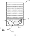
- FIG. 1 shows a rear view of a typical refrigeration appliance 1.
- Mains cable 2 links between mains supply plug 3 and the appliance, terminating in the motorcompressor control 5 mounted on the side of motorcompressor 4.
- the compressor control 5 typically manages the starting and overload protection for the compressor and includes connections for incoming mains electricity supply, and connections to a thermostatic switch (typically electromechanical) and to an optional door switch and interior light.
- cable 6 connects the control 5 to other facilities in the appliance such as a thermostat or interior light.
- a run capacitor (not shown) connecting to the control 5.
- the mains cable typically terminates in "spade"/"faston” and/or screwed terminals that are manually fitted onto mating connection tabs built into the control assembly.
- a cable clamp in the form of a plastic bridge secured by screws, fixes the cable to the mechanical body of the control to prevent movement of terminals or break of the wires as a result of pulling the cable.
- Figure 2a shows an end view of a typical assembly of control 5 onto motorcompressor 4.
- Figure 2b is a sectional side view and
- Figure 2c is an end view with cover moulding 10 removed to show control body moulding 8, cable clamp 11, and terminals 12 and 13 enclosed within.
- Cover for the assembly is often as two mouldings, illustrated as 9 and 10 to provide access to make the connections but then covered to inhibit ingress of water from above (e.g. from the evaporator tray 7.
- the control assembly fixes to compressor fence 14, a plate that is integral with the housing of the motorcompressor.
- Detachable cables are well known for other appliances and equipment and offer advantages such as the ability to substitute different types, for different geographic markets that use different types of mains plug.
- Background prior art can be found in: US 6,704,202 B1 and GB 2 435 554 A .
- a further benefit that is sought is reduction of cost of components and of assembly and test of the appliance.
- Refrigeration appliances use high voltages which are hazardous if the conductors are not properly protected. It is essential to protect against hazard in conditions both of normal and abnormal use. A particular requirement applies to the mains supply cable, it has to resist strong pulling and twisting without detaching or exposing hazardous voltages. This is compatible with the requirement for a detachable connection to resist vibration from the normal operation of the motorcompressor. However, the force applied is transmitted through the control to the body of the motorcompressor. So the fixing of the control onto the motorcompressor also has to resist high forces and this may be difficult to achieve at low cost. Particularly to minimise manufacturing cost, the assembly of the control onto the motorcompressor needs to be quick and preferably without screws. If this fixing is not sufficiently robust to withstand pulling of the cable there would be the risk that the control becomes detached from the compressor, exposing hazardous voltages.
- the invention is set out in claim 1.
- a domestic refrigerator or freezer comprising: a thermally insulated cooled zone; a cooling system to cool said cooled zone, said cooling system comprising a mains powered compressor; a compressor control mounted on said compressor, to control operation of said compressor, said compressor control including a mains power supply connection for an incoming mains power supply for said compressor; a cover for said mains power supply connection of said compressor control to inhibit water ingress to said mains power supply connection, and a mains power supply cable to provide said incoming mains power supply; wherein said mains power supply connection comprises a two-part, uncouplable electrical mains power supply connector co-located with said compressor control and beneath said cover, said two-part, uncouplable electrical mains supply connector having a first part connected to said mains power supply connection of said compressor control and a mating part connected to said mains power supply cable, such that said mains power supply cable is detachable from said domestic refrigerator by means of said electrical mains power supply connector.
- the parts of the mains power supply connector are detatchably held together in such a way that they resist detachment of the mains power supply cable by a small force, such as vibration of the compressor, but permit detachment of the mains power supply cable when a larger force, in particular greater than a threshold force is applied.
- a threshold force is such that when a disengagement force is applied to the mains power supply cable the parts of the mains power supply connector separate or detach from one another rather than the compressor control being detached from the compressor.
- a locking feature is provided to hold the parts of the mains power supply connector together until a force greater than the threshold force is applied.
- a portion of the refrigerator in particular a portion of the compressor control cover, is arranged to bear upon or otherwise lock the mating part of the connector connected to the mains power supply cable into place.
- the mating part of the mains power supply connector may bear a physical feature such as a flange over which the cover fits to resist detachment of the mains power supply cable.
- the first and mating parts of the mains power supply connector may have a locking action or means which is releasable substantially without damage when sufficient force is applied.
- the connector is of a push-and-turn type having portions which interengage. Preferably, with sufficient force, the portions can be pulled past one another, but this is not essential.
- one or more contacts of the connector may be shaped or sprung so that the parts of the connector, more particularly the contacts, are provided with a form of detent means. For example in a simple approach one connector portion may be sprung and another provided with a bump over which the sprung portion moves. In a still further approach the parts of the connector may be given a friction fit such that they do not substantially disengage until sufficient disengagement force is applied.
- the cover comprises first and second cover portions which are configured to mutually engage with one another to fasten over the mains power supply connection.
- One or both of these cover portions are provided with a catch to enable one cover portion to be disengaged from the other on application of a sufficient force to the mating part of the connector via the mains power supply cable.
- the catch may comprise a plastic moulding with a pair of opposing faces or ramps; the configuration of these features can be varied to vary the detachment force.
- the first and second cover portions may be one-piece moulded and provided with a living hinge; alternatively the portions may be physically separable one from the other.
- the domestic refrigerator or freezer appliance comprises a water-resistant cover to cover said mains power supply connection of said compressor control to inhibit water ingress to the mains power supply connection. Therefore the system incorporates a technique to inhibit water ingress.
- the cover has an outside edge which (when the cover is closed) is located above the mains power supply cable (which may be the portion of the mains power supply cable inside the connector).
- the mating part of the mains power supply connector connected to the mains cable is partially or wholly within the outside edge of the cover.
- this outside edge may be provided with a drip-inhibiting formation to inhibit water drips from running under the outside edge towards the mating part of the mains power supply connector.
- a drip-inhibiting formation may comprise a groove or recess in a plastic moulding behind the outside edge of the cover (that is towards an interior of the covered region).
- the disclosure provides a method of providing a detachable mains cable for a domestic refrigerator or freezer, the domestic refrigerator or freezer comprising: a thermally insulated cooled zone; a cooling system to cool said cooled zone, said cooling system comprising a mains powered compressor; a compressor control mounted on said compressor, to control operation of said compressor, said compressor control including a mains power supply connection for an incoming mains power supply for said compressor; a cover for said mains power supply connection of said compressor control to inhibit water ingress to said mains power supply connection, and a mains power supply cable to provide said incoming mains power supply; the method comprising: co-locating a two-part uncouplable electrical mains power supply connector with said compressor located beneath said cover, connecting a first part of said connector to said mains power supply connection of said compressor control and connecting a mating part of said connector to said mains power supply cable, and arranging said parts of said mains power supply connector to be held together to resist detachment of said mains
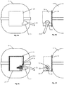
- Figure 3a shows an end view
- Figure 3b a side view
- Figure 3c a side view with cover 15 opened to provide access to make or break the mains connection
- Figure 3d an end view with cover 15b opened and connector 18 removed.
- Cover 15 is provided in two parts, 15a and 15b preferably hinged together at 15c, for example using a moulded "living hinge" so that the entire cover component can be injection-moulded in one operation.
- Body 19 of the control is enclosed within the cover and fixes onto the compressor fence 14 or otherwise onto the compressor. It is provided with a receptacle 21 and plug contacts 22 to accept a mains supply socket 18 that is fitted to the end of the mains supply cable 17.
- the connector is a type to the international standard IEC60320 C13 (for the cable socket) and C14 for the plug that is integral with the body 19.
- a special type of connector may be used to prevent use of standard types of mains cable assemblies.
- the connector is engaged by a simple push-fit, for example socket 18 pushes into receptacle 21 (preferably moulded into body 19), so that contacts 22 engage with the corresponding contact in socket 18.
- Cover 15b is subsequently hinged down so the socket is retained into the receptacle 21.
- Cover 15b is retained in the down position by one or more clips (one is illustrated as 16a and 16b) integral with the cover.
- the shape of the cover is arranged so that, in the down position, it sheds water falling from above to inhibit ingress into the control or the connector.
- the latches e.g. 16a 16b
- cover 15b can be raised, allowing the connector to be removed.
- FIG. 4 An example is Illustrated in Figures 4 , 5 and 6 .
- mains supply cable 25, fitted with connector 23, connects to the control assembly by fitting into features moulded as part of control body 26.
- Cover 24 substantially inhibits ingress of falling water to body 26.
- Connector 23 is arranged to be largely axisymmetric, allowing it to be pushed into the corresponding feature in the body then it can be rotated. More detailed views of connector 23 are in Figure 5a (end view), 5b (side view), 5c (top view) and 5d (perspective view).
- Connector 23 optionally includes axial contact 32 and radial contacts 30 and 31.
- Flange 33 is on the outside of the body of the connector. To insert the connector into control body 26, the connector is first axially aligned with the corresponding features of body 26, and with flange 33 lowermost. It is then pushed into the body and subsequently rotated by approximately 180 degrees so that flange 33 is captured behind the projecting face 24a of cover 24. The engagement of flange 33 behind face 24a inhibits connector 23 from being pulled or vibrating free of the body 26.
- connector 23 and body 26 can be provided with latch or bump features which resist rotation of 23 after it has been engaged.
- Figure 4d shows a side view of body 26 but with the connector 23 and cover 24 both removed.
- a number of contacts may be included: Axial contact 29 to connect with axial contact 32 of connector 23, and radial contacts 27 and 28 to connect with radial contacts 30 and 31 (respectively) of connector 23.
- axial contacts 29 and 32 may be used for an Earth connection because they can be arranged to make contact before the radial contacts when the connector is fitted to the body.
- Connector 23 is designed to inhibit hazard of electrical shock (for example, according to international safety standards). Particularly the radial cavity that holds contacts 30 and 31 is arranged with a small radial width so that the contacts are not accessible. Note also that the orientation of the radial contacts is such that they make contact only when connector 23 has been rotated sufficiently to engage flange 33 behind face 24a.
- FIG. 6 shows further views of the control assembly on the motorcompressor, without connector 23 fitted, to illustrate the arrangement of cover 24, body 26 and the features that mate with connector 23.
- One strategy is to ensure that the fixing of the control onto the motorcompressor is sufficiently robust to withstand the force but this may make the manufacture more expensive.
- An alternative strategy is to make the locking of the detachable cable connector less robust, so that when high pulling or twisting forces are applied the connector detaches from the control before the control detaches from the motorcompressor. This is safe behaviour because a mains power connector is generally configured so that there is no shock hazard when it is detached.
- the locking force of such a connector can be reduced.
- the locking features of the components are arranged so that they deflect sufficiently to allow disengagement when high forces are applied.
- the deflection is preferably temporary so that the connector can be reengaged and locked so the system continues to operate normally and provide the desired performance and safety. Breaking of the features is not desired as this is likely to reduce the subsequent locking performance.
- the locking features are designed to give a predictable and accurate threshold force for disengagement of the connector. To accommodate geometric tolerances, this generally requires larger size of features and of deflection distances.
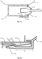
- Figure 7a illustrates a possible design for the catch 16 that locks the cover 15b which, in turn, maintains the engagement of the connector 18 in the control.
- the catch parts 16a and 16b are arranged in a manner very commonly used for holding moulded plastic components together.
- Feature 16a is elongated and provided with and overlap over feature 16b.
- To engage or disengage the catch feature 16a deflects away from housing 15a. This is facilitated by ramps on one or both features. Generally two sets of ramps may be provided, one set to facilitate engagement and another set for disengagement.
- the engage/disengage force depends on several factors that can be preset in the design. Referring to Figure 7b , for the disengage force, it depends mainly on the:
- Engagements and locks as described above can resist high levels of pulling, twisting and vibration. It is important, however, to consider separately normal and abnormal conditions. In normal conditions, it is desirable that the connector should remain engaged so the appliance continues to operate. In abnormal conditions it is acceptable for the connector to disengage. For a particular appliance it could be that only a low retention force is needed for normal operation (e.g. if the motorcompressor exhibits only low levels of vibration) and that abnormal conditions impose a high level of force. In this case, the connector engagement may only need low retention force, and that it is acceptable that the retention force can vary considerably. The retention force must remain above the minimum needed for normal conditions but below a level that e.g. could cause detachment of the control from the motorcompressor. It is possible to provide a low retention force, but with considerable tolerance, simply by the friction of the engagement of the contacts in the detachable connector with the corresponding contacts in the control. So, in some applications, it may not be necessary to provide additional locking features.
- the invention inhibits ingress of water or other liquids that fall generally from above the motorcompressor or control.
- the control is enclosed in an water resistant cover (illustrated as 15, 24 or 38). This substantially covers the top and sides of the control so that liquids falling from above run down the sides and drop off as illustrated in Figure 8a .
- a detachable cable (39 and 40) enters from the side of the control. This increases the risk that liquid could enter the connection region or elsewhere into the control, causing malfunction or shock hazard.
- the cover includes features to reduce the risk of this.
- a suitable arrangement is a "drip edge" 41 which forces the liquid to break away from the cover and to drop vertically. The liquid then may fall harmlessly onto the connector or cable where they pass under the cover. These are arranged to be impervious parts of the cable/connector so are not affected by the liquid.
- the connector 42 may be provided with a similar drip edge feature 43 to ensure the liquid drops off the connector rather than running along its surface and into the region of the connections.
- an effective drip edge should have sufficient downwards extension 44 and lateral clearance 45 to ensure that the liquid drops off.
- Minimum dimensions for 44 and 45 depend on the material and surface finish of the cover, presence of any surface contamination (e.g. dust) and the nature of the liquid.
- each should preferably be a minimum of 2mm and preferably 3mm or more.
- the liquid may adhere to the surface of the cover and run along the underside of the cover where (for example) it projects over the connector. This is illustrated in Figure 8c , and could lead to ingress or liquid into the connector region or elsewhere in the control causing malfunction or a shock hazard.
- the connector and engagement features are designed for manufacture and assembly, and test at low cost.
- the supply connector e.g. as illustrated generally as 18 or 23
- the supply connector is made by automatic or semi-automatic termination and moulding processes as used typically for connectors to the international standard IEC60320 C13.
- the corresponding engagement features in the control body are made by a moulding process used also to make the whole or part of the control body
- Contacts in the control that connect with the supply connector are made integral with other features desirable for interconnection within the control.
- they can be made by low-cost pressing operations to make complex shapes that allow the electrical connections to route within the control.
- they are arranged so that they can be assembled to supporting and other components by automated assembly methods
- the supply and optional earth contact in the control are accessible for a supply connection to made by a special automated connector. This enables automated testing of the appliance as part of the manufacturing process.
Landscapes
- Engineering & Computer Science (AREA)
- Chemical & Material Sciences (AREA)
- Combustion & Propulsion (AREA)
- Physics & Mathematics (AREA)
- Mechanical Engineering (AREA)
- Thermal Sciences (AREA)
- General Engineering & Computer Science (AREA)
- Details Of Connecting Devices For Male And Female Coupling (AREA)
- Compressor (AREA)
Claims (5)
- Haushaltskühlschrank oder Gefriergerät (1), wobei der Haushaltskühlschrank oder das Gefriergerät umfasst:einen thermisch isolierten gekühlten Bereich; undein Kühlsystem zum Kühlen des gekühlten Bereichs, wobei das Kühlsystem einen netzgespeisten Kompressor (4) umfasst;eine externe Netzverbindung für eine in das Gerät eingehende Netzversorgung; undein Netzversorgungskabel (17, 25), um die eingehende Netzversorgung bereitzustellen;und eine Kompressorsteuerung (19, 26), um den Betrieb des Kompressors zu steuern, wobei die Kompressorsteuerung die Netzverbindung umfasst;wobei die Netzverbindung einen zweiteiligen entkoppelbaren elektrischen Netzanschluss (18, 21, 23) umfasst, wobei der zweiteilige entkoppelbare elektrische Netzanschluss einen ersten Teil (18, 23), der mit der Netzverbindung der Kompressorsteuerung verbunden ist, und einen Kopplungsteil (21) umfasst, der mit dem Netzversorgungskabel verbunden ist, sodass das Netzversorgungskabel vom Haushaltskühlschrank mittels des elektrischen Netzanschlusses lösbar ist,gekennzeichnet durcheine wasserbeständige Abdeckung (15, 24, 38), zur Abdeckung der Netzverbindung der Kompressorsteuerung, um zu verhindern, dass Wasser in die Netzverbindung von oben eindringt,wobei die Kompressorsteuerung auf dem Kompressor montiert ist (14), und wobei die Netzverbindung gemeinsam mit der Kompressorsteuerung unterhalb der Abdeckung angeordnet ist,wobei die Abdeckung erste und zweite Abdeckungsabschnitte (15a, b) umfasst, die konfiguriert sind, um miteinander einzugreifen, um sich aneinander oberhalb des Netzanschlusses zu befestigen, um die Teile des Anschlusses zusammenzuhalten, und wobei einer oder beide der ersten und zweiten Abdeckungsteile eine Klinke (16a, b) umfasst, die ermöglicht, dass die ersten und zweiten Abdeckungsteile beim Aufbringen einer Entkopplungskraft auf das Netzversorgungskabel entkoppelt werden, sodass, wenn die Entkopplungskraft auf das Netzversorgungskabel aufgebracht wird, die Teile des Netzanschlusses sich voneinander trennen oder lösen, anstatt dass die Kompressorsteuerung vom Kompressor gelöst wird.
- Haushaltkühlschrank nach Anspruch 1, wobei die Klinke erste und zweite miteinander eingreifende Merkmale (16a, b) umfasst, von denen mindestens eins eine Rampe aufweist, die das Lösen der Merkmale erleichtert.
- Haushaltkühlschrank nach Anspruch 1 oder 2, wobei die ersten und zugehörigen Teile des Netzanschlusses konfiguriert sind, um miteinander durch eine Drück-und-Drehwirkung einzugreifen.
- Haushaltkühlschrank nach Anspruch 1, 2 oder 3, wobei der zugehörige Teil des Netzanschlusses ein physisches Merkmal (33) trägt, über welches die Abdeckung passt, um einem Lösen des Netzversorgungskabels zu widerstehen.
- Haushaltkühlschrank nach einem der vorhergehenden Ansprüche, wobei die Abdeckung eine Abtropfkante (41) aufweist, die, wenn die Abdeckung geschlossen ist, sich oberhalb des Netzversorgungskabels befindet, wobei der zugehörige Teil des Netzanschlusses, wenn die Abdeckung geschlossen ist, sich teilweise oder vollständig innerhalb der Abtropfkante der Abdeckung befindet, um zu verhindern, dass Wasser abtropft und unterhalb der Abtropfkante zu dem zugehörigen Teil des Netzanschlusses läuft.
Applications Claiming Priority (1)
| Application Number | Priority Date | Filing Date | Title |
|---|---|---|---|
| GBGB1101899.1A GB201101899D0 (en) | 2011-02-04 | 2011-02-04 | Refrigerator power connector |
Publications (3)
| Publication Number | Publication Date |
|---|---|
| EP2485340A2 EP2485340A2 (de) | 2012-08-08 |
| EP2485340A3 EP2485340A3 (de) | 2017-05-03 |
| EP2485340B1 true EP2485340B1 (de) | 2019-10-23 |
Family
ID=43836178
Family Applications (1)
| Application Number | Title | Priority Date | Filing Date |
|---|---|---|---|
| EP12152732.9A Active EP2485340B1 (de) | 2011-02-04 | 2012-01-26 | Netzanschluss für Kühlschrank |
Country Status (2)
| Country | Link |
|---|---|
| EP (1) | EP2485340B1 (de) |
| GB (1) | GB201101899D0 (de) |
Families Citing this family (1)
| Publication number | Priority date | Publication date | Assignee | Title |
|---|---|---|---|---|
| DE102013225650A1 (de) * | 2013-12-11 | 2015-06-11 | BSH Hausgeräte GmbH | Haushaltskältegerät mit einer spezifischen Begrenzungswand eines Maschinenraums |
Family Cites Families (3)
| Publication number | Priority date | Publication date | Assignee | Title |
|---|---|---|---|---|
| JP3886295B2 (ja) * | 1999-06-15 | 2007-02-28 | 松下冷機株式会社 | 冷凍システムのパワー制御装置およびコンプレッサ |
| IT250075Y1 (it) * | 2000-06-20 | 2003-07-07 | Whirlpool Co | Centralina raggruppatrice di componenti elettronici per frigoriferi congelatori e simili apparecchi |
| GB2435554A (en) * | 2006-02-27 | 2007-08-29 | Chih-Lung Lin | Watertight electric socket |
-
2011
- 2011-02-04 GB GBGB1101899.1A patent/GB201101899D0/en not_active Ceased
-
2012
- 2012-01-26 EP EP12152732.9A patent/EP2485340B1/de active Active
Non-Patent Citations (1)
| Title |
|---|
| None * |
Also Published As
| Publication number | Publication date |
|---|---|
| EP2485340A2 (de) | 2012-08-08 |
| EP2485340A3 (de) | 2017-05-03 |
| GB201101899D0 (en) | 2011-03-23 |
Similar Documents
| Publication | Publication Date | Title |
|---|---|---|
| US10247470B2 (en) | Refrigerator with removable display | |
| EP3214395B1 (de) | Kühlschrank | |
| EP2385588B1 (de) | Sicherer elektrischer ausgang | |
| EP2843326B1 (de) | Kühlschrank | |
| EP2816670B1 (de) | Elektrischer Steckverbinder | |
| WO2015017387A1 (en) | Access-restricted electrical receptacle | |
| US20120275085A1 (en) | Electrical component enclosure | |
| CN201966087U (zh) | 电气开关锁紧组件 | |
| AU2008210254A1 (en) | A connector socket, a connector plug, and an appliance fitted with a connector | |
| EP2485340A2 (de) | Netzanschluss für Kühlschrank | |
| US8531828B2 (en) | Storage device carrier having a pivoting panel | |
| CN102494501A (zh) | 瓶托及具有该瓶托的冰箱 | |
| CN203731780U (zh) | 制冷器具 | |
| JP2008112613A (ja) | レバー式コネクタ | |
| CN111164365B (zh) | 具有对用于遮盖后置件的盖的特定固定的家用制冷器具 | |
| CN106257210A (zh) | 具有冰桶锁定装置的冰箱以及安装冰桶锁定装置的方法 | |
| JP2011256804A (ja) | 圧縮機及び冷蔵庫 | |
| CN105814379B (zh) | 具有特定的机械室边界壁的家用制冷器具 | |
| CN214484296U (zh) | 一种抽屉式容器组件及空气炸锅 | |
| EP2053322A2 (de) | Anordnung für einen elektrischen Anschluss, Starter und Schutz eines elektrischen Motorenkompressors, der mit einem hermetischen metallischen Gehäuse abgedichtet ist | |
| EP2906887B1 (de) | Kältegerät mit magnetventil | |
| KR101839655B1 (ko) | 냉장 및 냉동고용 컨트롤러 | |
| KR20210078624A (ko) | 커넥터 조립체 | |
| CN111981752A (zh) | 冰箱 | |
| CN107636409B (zh) | 冷藏库 |
Legal Events
| Date | Code | Title | Description |
|---|---|---|---|
| PUAI | Public reference made under article 153(3) epc to a published international application that has entered the european phase |
Free format text: ORIGINAL CODE: 0009012 |
|
| AK | Designated contracting states |
Kind code of ref document: A2 Designated state(s): AL AT BE BG CH CY CZ DE DK EE ES FI FR GB GR HR HU IE IS IT LI LT LU LV MC MK MT NL NO PL PT RO RS SE SI SK SM TR |
|
| AX | Request for extension of the european patent |
Extension state: BA ME |
|
| PUAL | Search report despatched |
Free format text: ORIGINAL CODE: 0009013 |
|
| AK | Designated contracting states |
Kind code of ref document: A3 Designated state(s): AL AT BE BG CH CY CZ DE DK EE ES FI FR GB GR HR HU IE IS IT LI LT LU LV MC MK MT NL NO PL PT RO RS SE SI SK SM TR |
|
| AX | Request for extension of the european patent |
Extension state: BA ME |
|
| RIC1 | Information provided on ipc code assigned before grant |
Ipc: H01R 13/58 20060101ALI20170325BHEP Ipc: F25D 23/00 20060101ALI20170325BHEP Ipc: F25B 31/00 20060101ALI20170325BHEP Ipc: H01R 13/639 20060101ALI20170325BHEP Ipc: H01R 13/506 20060101ALI20170325BHEP Ipc: H01R 13/52 20060101AFI20170325BHEP |
|
| STAA | Information on the status of an ep patent application or granted ep patent |
Free format text: STATUS: REQUEST FOR EXAMINATION WAS MADE |
|
| 17P | Request for examination filed |
Effective date: 20171101 |
|
| RBV | Designated contracting states (corrected) |
Designated state(s): AL AT BE BG CH CY CZ DE DK EE ES FI FR GB GR HR HU IE IS IT LI LT LU LV MC MK MT NL NO PL PT RO RS SE SI SK SM TR |
|
| GRAP | Despatch of communication of intention to grant a patent |
Free format text: ORIGINAL CODE: EPIDOSNIGR1 |
|
| STAA | Information on the status of an ep patent application or granted ep patent |
Free format text: STATUS: GRANT OF PATENT IS INTENDED |
|
| RIC1 | Information provided on ipc code assigned before grant |
Ipc: H01R 13/52 20060101AFI20190417BHEP Ipc: H01R 13/506 20060101ALI20190417BHEP Ipc: H01R 13/639 20060101ALI20190417BHEP Ipc: H01R 13/58 20060101ALI20190417BHEP Ipc: F25B 31/00 20060101ALI20190417BHEP Ipc: F25D 23/00 20060101ALI20190417BHEP |
|
| INTG | Intention to grant announced |
Effective date: 20190517 |
|
| GRAS | Grant fee paid |
Free format text: ORIGINAL CODE: EPIDOSNIGR3 |
|
| GRAA | (expected) grant |
Free format text: ORIGINAL CODE: 0009210 |
|
| STAA | Information on the status of an ep patent application or granted ep patent |
Free format text: STATUS: THE PATENT HAS BEEN GRANTED |
|
| AK | Designated contracting states |
Kind code of ref document: B1 Designated state(s): AL AT BE BG CH CY CZ DE DK EE ES FI FR GB GR HR HU IE IS IT LI LT LU LV MC MK MT NL NO PL PT RO RS SE SI SK SM TR |
|
| REG | Reference to a national code |
Ref country code: GB Ref legal event code: FG4D |
|
| REG | Reference to a national code |
Ref country code: CH Ref legal event code: EP |
|
| REG | Reference to a national code |
Ref country code: IE Ref legal event code: FG4D |
|
| REG | Reference to a national code |
Ref country code: DE Ref legal event code: R096 Ref document number: 602012065007 Country of ref document: DE |
|
| REG | Reference to a national code |
Ref country code: AT Ref legal event code: REF Ref document number: 1194724 Country of ref document: AT Kind code of ref document: T Effective date: 20191115 |
|
| REG | Reference to a national code |
Ref country code: NL Ref legal event code: MP Effective date: 20191023 |
|
| REG | Reference to a national code |
Ref country code: LT Ref legal event code: MG4D |
|
| PG25 | Lapsed in a contracting state [announced via postgrant information from national office to epo] |
Ref country code: PT Free format text: LAPSE BECAUSE OF FAILURE TO SUBMIT A TRANSLATION OF THE DESCRIPTION OR TO PAY THE FEE WITHIN THE PRESCRIBED TIME-LIMIT Effective date: 20200224 Ref country code: BG Free format text: LAPSE BECAUSE OF FAILURE TO SUBMIT A TRANSLATION OF THE DESCRIPTION OR TO PAY THE FEE WITHIN THE PRESCRIBED TIME-LIMIT Effective date: 20200123 Ref country code: FI Free format text: LAPSE BECAUSE OF FAILURE TO SUBMIT A TRANSLATION OF THE DESCRIPTION OR TO PAY THE FEE WITHIN THE PRESCRIBED TIME-LIMIT Effective date: 20191023 Ref country code: PL Free format text: LAPSE BECAUSE OF FAILURE TO SUBMIT A TRANSLATION OF THE DESCRIPTION OR TO PAY THE FEE WITHIN THE PRESCRIBED TIME-LIMIT Effective date: 20191023 Ref country code: LT Free format text: LAPSE BECAUSE OF FAILURE TO SUBMIT A TRANSLATION OF THE DESCRIPTION OR TO PAY THE FEE WITHIN THE PRESCRIBED TIME-LIMIT Effective date: 20191023 Ref country code: GR Free format text: LAPSE BECAUSE OF FAILURE TO SUBMIT A TRANSLATION OF THE DESCRIPTION OR TO PAY THE FEE WITHIN THE PRESCRIBED TIME-LIMIT Effective date: 20200124 Ref country code: NO Free format text: LAPSE BECAUSE OF FAILURE TO SUBMIT A TRANSLATION OF THE DESCRIPTION OR TO PAY THE FEE WITHIN THE PRESCRIBED TIME-LIMIT Effective date: 20200123 Ref country code: SE Free format text: LAPSE BECAUSE OF FAILURE TO SUBMIT A TRANSLATION OF THE DESCRIPTION OR TO PAY THE FEE WITHIN THE PRESCRIBED TIME-LIMIT Effective date: 20191023 Ref country code: LV Free format text: LAPSE BECAUSE OF FAILURE TO SUBMIT A TRANSLATION OF THE DESCRIPTION OR TO PAY THE FEE WITHIN THE PRESCRIBED TIME-LIMIT Effective date: 20191023 Ref country code: NL Free format text: LAPSE BECAUSE OF FAILURE TO SUBMIT A TRANSLATION OF THE DESCRIPTION OR TO PAY THE FEE WITHIN THE PRESCRIBED TIME-LIMIT Effective date: 20191023 Ref country code: ES Free format text: LAPSE BECAUSE OF FAILURE TO SUBMIT A TRANSLATION OF THE DESCRIPTION OR TO PAY THE FEE WITHIN THE PRESCRIBED TIME-LIMIT Effective date: 20191023 |
|
| PG25 | Lapsed in a contracting state [announced via postgrant information from national office to epo] |
Ref country code: RS Free format text: LAPSE BECAUSE OF FAILURE TO SUBMIT A TRANSLATION OF THE DESCRIPTION OR TO PAY THE FEE WITHIN THE PRESCRIBED TIME-LIMIT Effective date: 20191023 Ref country code: IS Free format text: LAPSE BECAUSE OF FAILURE TO SUBMIT A TRANSLATION OF THE DESCRIPTION OR TO PAY THE FEE WITHIN THE PRESCRIBED TIME-LIMIT Effective date: 20200224 Ref country code: HR Free format text: LAPSE BECAUSE OF FAILURE TO SUBMIT A TRANSLATION OF THE DESCRIPTION OR TO PAY THE FEE WITHIN THE PRESCRIBED TIME-LIMIT Effective date: 20191023 |
|
| PG25 | Lapsed in a contracting state [announced via postgrant information from national office to epo] |
Ref country code: AL Free format text: LAPSE BECAUSE OF FAILURE TO SUBMIT A TRANSLATION OF THE DESCRIPTION OR TO PAY THE FEE WITHIN THE PRESCRIBED TIME-LIMIT Effective date: 20191023 |
|
| REG | Reference to a national code |
Ref country code: DE Ref legal event code: R097 Ref document number: 602012065007 Country of ref document: DE |
|
| PG2D | Information on lapse in contracting state deleted |
Ref country code: IS |
|
| PG25 | Lapsed in a contracting state [announced via postgrant information from national office to epo] |
Ref country code: EE Free format text: LAPSE BECAUSE OF FAILURE TO SUBMIT A TRANSLATION OF THE DESCRIPTION OR TO PAY THE FEE WITHIN THE PRESCRIBED TIME-LIMIT Effective date: 20191023 Ref country code: DK Free format text: LAPSE BECAUSE OF FAILURE TO SUBMIT A TRANSLATION OF THE DESCRIPTION OR TO PAY THE FEE WITHIN THE PRESCRIBED TIME-LIMIT Effective date: 20191023 Ref country code: RO Free format text: LAPSE BECAUSE OF FAILURE TO SUBMIT A TRANSLATION OF THE DESCRIPTION OR TO PAY THE FEE WITHIN THE PRESCRIBED TIME-LIMIT Effective date: 20191023 Ref country code: CZ Free format text: LAPSE BECAUSE OF FAILURE TO SUBMIT A TRANSLATION OF THE DESCRIPTION OR TO PAY THE FEE WITHIN THE PRESCRIBED TIME-LIMIT Effective date: 20191023 Ref country code: IS Free format text: LAPSE BECAUSE OF FAILURE TO SUBMIT A TRANSLATION OF THE DESCRIPTION OR TO PAY THE FEE WITHIN THE PRESCRIBED TIME-LIMIT Effective date: 20200223 |
|
| REG | Reference to a national code |
Ref country code: AT Ref legal event code: MK05 Ref document number: 1194724 Country of ref document: AT Kind code of ref document: T Effective date: 20191023 |
|
| PLBE | No opposition filed within time limit |
Free format text: ORIGINAL CODE: 0009261 |
|
| STAA | Information on the status of an ep patent application or granted ep patent |
Free format text: STATUS: NO OPPOSITION FILED WITHIN TIME LIMIT |
|
| PG25 | Lapsed in a contracting state [announced via postgrant information from national office to epo] |
Ref country code: MC Free format text: LAPSE BECAUSE OF FAILURE TO SUBMIT A TRANSLATION OF THE DESCRIPTION OR TO PAY THE FEE WITHIN THE PRESCRIBED TIME-LIMIT Effective date: 20191023 Ref country code: SM Free format text: LAPSE BECAUSE OF FAILURE TO SUBMIT A TRANSLATION OF THE DESCRIPTION OR TO PAY THE FEE WITHIN THE PRESCRIBED TIME-LIMIT Effective date: 20191023 Ref country code: SK Free format text: LAPSE BECAUSE OF FAILURE TO SUBMIT A TRANSLATION OF THE DESCRIPTION OR TO PAY THE FEE WITHIN THE PRESCRIBED TIME-LIMIT Effective date: 20191023 |
|
| REG | Reference to a national code |
Ref country code: CH Ref legal event code: PL |
|
| 26N | No opposition filed |
Effective date: 20200724 |
|
| REG | Reference to a national code |
Ref country code: BE Ref legal event code: MM Effective date: 20200131 |
|
| PG25 | Lapsed in a contracting state [announced via postgrant information from national office to epo] |
Ref country code: LU Free format text: LAPSE BECAUSE OF NON-PAYMENT OF DUE FEES Effective date: 20200126 |
|
| PG25 | Lapsed in a contracting state [announced via postgrant information from national office to epo] |
Ref country code: CH Free format text: LAPSE BECAUSE OF NON-PAYMENT OF DUE FEES Effective date: 20200131 Ref country code: BE Free format text: LAPSE BECAUSE OF NON-PAYMENT OF DUE FEES Effective date: 20200131 Ref country code: LI Free format text: LAPSE BECAUSE OF NON-PAYMENT OF DUE FEES Effective date: 20200131 Ref country code: AT Free format text: LAPSE BECAUSE OF FAILURE TO SUBMIT A TRANSLATION OF THE DESCRIPTION OR TO PAY THE FEE WITHIN THE PRESCRIBED TIME-LIMIT Effective date: 20191023 Ref country code: SI Free format text: LAPSE BECAUSE OF FAILURE TO SUBMIT A TRANSLATION OF THE DESCRIPTION OR TO PAY THE FEE WITHIN THE PRESCRIBED TIME-LIMIT Effective date: 20191023 |
|
| PG25 | Lapsed in a contracting state [announced via postgrant information from national office to epo] |
Ref country code: IE Free format text: LAPSE BECAUSE OF NON-PAYMENT OF DUE FEES Effective date: 20200126 |
|
| PG25 | Lapsed in a contracting state [announced via postgrant information from national office to epo] |
Ref country code: TR Free format text: LAPSE BECAUSE OF FAILURE TO SUBMIT A TRANSLATION OF THE DESCRIPTION OR TO PAY THE FEE WITHIN THE PRESCRIBED TIME-LIMIT Effective date: 20191023 Ref country code: MT Free format text: LAPSE BECAUSE OF FAILURE TO SUBMIT A TRANSLATION OF THE DESCRIPTION OR TO PAY THE FEE WITHIN THE PRESCRIBED TIME-LIMIT Effective date: 20191023 Ref country code: CY Free format text: LAPSE BECAUSE OF FAILURE TO SUBMIT A TRANSLATION OF THE DESCRIPTION OR TO PAY THE FEE WITHIN THE PRESCRIBED TIME-LIMIT Effective date: 20191023 |
|
| PG25 | Lapsed in a contracting state [announced via postgrant information from national office to epo] |
Ref country code: MK Free format text: LAPSE BECAUSE OF FAILURE TO SUBMIT A TRANSLATION OF THE DESCRIPTION OR TO PAY THE FEE WITHIN THE PRESCRIBED TIME-LIMIT Effective date: 20191023 |
|
| PGFP | Annual fee paid to national office [announced via postgrant information from national office to epo] |
Ref country code: GB Payment date: 20221208 Year of fee payment: 12 Ref country code: FR Payment date: 20221208 Year of fee payment: 12 |
|
| PGFP | Annual fee paid to national office [announced via postgrant information from national office to epo] |
Ref country code: IT Payment date: 20221213 Year of fee payment: 12 Ref country code: DE Payment date: 20221213 Year of fee payment: 12 |
|
| REG | Reference to a national code |
Ref country code: DE Ref legal event code: R119 Ref document number: 602012065007 Country of ref document: DE |
|
| GBPC | Gb: european patent ceased through non-payment of renewal fee |
Effective date: 20240126 |
|
| PG25 | Lapsed in a contracting state [announced via postgrant information from national office to epo] |
Ref country code: DE Free format text: LAPSE BECAUSE OF NON-PAYMENT OF DUE FEES Effective date: 20240801 |
|
| PG25 | Lapsed in a contracting state [announced via postgrant information from national office to epo] |
Ref country code: GB Free format text: LAPSE BECAUSE OF NON-PAYMENT OF DUE FEES Effective date: 20240126 |
|
| PG25 | Lapsed in a contracting state [announced via postgrant information from national office to epo] |
Ref country code: FR Free format text: LAPSE BECAUSE OF NON-PAYMENT OF DUE FEES Effective date: 20240131 |
|
| PG25 | Lapsed in a contracting state [announced via postgrant information from national office to epo] |
Ref country code: GB Free format text: LAPSE BECAUSE OF NON-PAYMENT OF DUE FEES Effective date: 20240126 Ref country code: FR Free format text: LAPSE BECAUSE OF NON-PAYMENT OF DUE FEES Effective date: 20240131 Ref country code: DE Free format text: LAPSE BECAUSE OF NON-PAYMENT OF DUE FEES Effective date: 20240801 |
|
| PG25 | Lapsed in a contracting state [announced via postgrant information from national office to epo] |
Ref country code: IT Free format text: LAPSE BECAUSE OF NON-PAYMENT OF DUE FEES Effective date: 20240126 |