EP2484846A2 - Underlay - Google Patents
Underlay Download PDFInfo
- Publication number
- EP2484846A2 EP2484846A2 EP11194744A EP11194744A EP2484846A2 EP 2484846 A2 EP2484846 A2 EP 2484846A2 EP 11194744 A EP11194744 A EP 11194744A EP 11194744 A EP11194744 A EP 11194744A EP 2484846 A2 EP2484846 A2 EP 2484846A2
- Authority
- EP
- European Patent Office
- Prior art keywords
- intermediate layer
- flexible intermediate
- underlay
- layer
- backsheet according
- Prior art date
- Legal status (The legal status is an assumption and is not a legal conclusion. Google has not performed a legal analysis and makes no representation as to the accuracy of the status listed.)
- Withdrawn
Links
Images

Classifications
-
- E—FIXED CONSTRUCTIONS
- E04—BUILDING
- E04F—FINISHING WORK ON BUILDINGS, e.g. STAIRS, FLOORS
- E04F15/00—Flooring
- E04F15/18—Separately-laid insulating layers; Other additional insulating measures; Floating floors
- E04F15/186—Underlayers covered with a mesh or the like
-
- E—FIXED CONSTRUCTIONS
- E04—BUILDING
- E04F—FINISHING WORK ON BUILDINGS, e.g. STAIRS, FLOORS
- E04F15/00—Flooring
- E04F15/02—Flooring or floor layers composed of a number of similar elements
- E04F15/02177—Floor elements for use at a specific location
- E04F15/02188—Floor elements for use at a specific location for use in wet rooms
-
- E—FIXED CONSTRUCTIONS
- E04—BUILDING
- E04F—FINISHING WORK ON BUILDINGS, e.g. STAIRS, FLOORS
- E04F15/00—Flooring
- E04F15/18—Separately-laid insulating layers; Other additional insulating measures; Floating floors
- E04F15/182—Underlayers coated with adhesive or mortar to receive the flooring
-
- E—FIXED CONSTRUCTIONS
- E04—BUILDING
- E04F—FINISHING WORK ON BUILDINGS, e.g. STAIRS, FLOORS
- E04F15/00—Flooring
- E04F15/18—Separately-laid insulating layers; Other additional insulating measures; Floating floors
- E04F15/20—Separately-laid insulating layers; Other additional insulating measures; Floating floors for sound insulation
- E04F15/203—Separately-laid layers for sound insulation
Definitions
- the invention relates to a backing sheet for laying under hard floor coverings.
- German Utility Model DE 20 2004 000 499 U1 describes a backsheet web in which a fabric layer held between webs has filling holes which are filled with mineral filler.
- This object is achieved in that it consists of at least three interconnected layers, namely of a nonwoven layer, an overlying flexible intermediate layer, and a cover fleece, wherein in the flexible Intermediate layer is a mineral filler bound with a plastic adhesive through which open channels are drawn.
- the lower non-woven layer allows the full-surface bonding of the underlay using all available floor adhesives from any surface. It ensures the decoupling of flooring and substrate.
- the flexible intermediate layer in which open longitudinal and / or transverse channels are arranged represents a large-volume pressure compensation layer, which ensures the flatness and the adaptation to the substrates.
- the cover fleece allows the full-surface and durable bonding of the various floor coverings on the underlay.
- the simple construction allows a cost-effective production of the underlay.
- the open channels provide a flexibility of the intermediate layer and thus a good flatness on the ground.
- the open channels allow a roll-up of the backing sheet and thus a good transport option.
- the open channels in the flexible intermediate layer have a coarse grid with a spacing of 10 to 30 mm. They are in one direction or are pulled crosswise.
- a wave-shaped arrangement of the open channels has proved to be particularly advantageous, since a uniform distribution of the pressure stability and tensile strength in the longitudinal and transverse directions is achieved.
- the underlay is further stabilized under high stress by an additional stabilizing fabric with high tensile strength in the longitudinal and transverse directions is on the lower nonwoven layer.
- An additional sealing film under the cover fleece forms a sealing layer against moisture from above as well as a vapor barrier from below.
- the underlay can thus be used in wet areas and also outdoors. It protects floors and false ceilings against the damaging effects of surface and service water. Furthermore, moisture-sensitive coverings, such as wood in parquet or laminate floors, protected against negative residual moisture from the substrate. So Drying times can be significantly reduced before laying floor coverings.
- the filler is preferably made of sand. It is inexpensive, mixes well with plastic glue and has a high specific weight. The high specific weight prevents the floor from becoming hollow when used with hard footwear.
- plastic fibers as the material for the nonwovens allows for easy resumption of the flooring from the backing sheet and easy removal of the backing sheet from the substrate.
- the underlay design described herein allows a specific gravity between 0.1 and 0.4 grams per square centimeter. Also, a total thickness of such a web of less than 3 mm is possible. Thus, it also meets the requirements for a flat floor construction.
- a floor with a hard surface such as parquet, laminate, natural stone, ceramics, tiles or stone slabs, is conveniently constructed with a underlay, as described so far, simple and safe.
- the backing sheet is coated with a suitable adhesive, e.g. a mineral adhesive at screed, glued to the supporting substrate. It is directly, without further intermediate layers, glued to the floor covering with an adhesive. So there is a very simple construction of the floor.
- the underlay acts as decoupling and sealing and significantly reduces room and footfall sound levels.
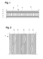
- Fig. 1 the layered structure of the backing sheet 7 is shown. It consists of the lower nonwoven layer 1, the flexible intermediate layer 3 and the upper Abdeckvlies. 5
- the stabilizing fabric 2 is optionally located on the lower nonwoven layer 1.
- the sealing film 4 can optionally be inserted under the cover fabric 5.
- the flexible intermediate layer 3 is a mixture of sand with plastic adhesive, in which the open channels 6 are incorporated. These serve as a pressure equalization layer. This results in a flat, compact underlay, which can be easily installed and glued.
- Fig. 2 a top view of the backing sheet 7 is shown.
- the open channels 6 extend in a wide-meshed grid. These are shown here in waveform and one direction. They are incorporated in the sand-plastic adhesive mixture.
- Fig. 3 the structure of a floor with the backing sheet 7 is shown in cross section.
- the backing sheet 7 is glued with a suitable adhesive 8.
- the floor covering 11 is glued with a mineral adhesive 9.
- the underlay web 7 also spans joints 13 and cracks 12 in the ground. Strains due to the joints 13 and cracks 12 are collected.
- the three-layer material has a thickness of less than 3 mm.
Abstract
Description
Die Erfindung betrifft eine Unterlagsbahn zur Verlegung unter harten Bodenbelägen.The invention relates to a backing sheet for laying under hard floor coverings.
Es ist heute gängige Praxis, Bodenbeläge schwimmend, d.h. ohne direkten Verbund zum Untergrund zu verlegen. Dazu wird auf den tragenden Untergrund eine Zwischenschicht lose aufgelegt, fixiert oder verklebt, auf die dann die Bodenbeläge verlegt werden. So können sie leicht wieder aufgenommen werden, wobei der Untergrund nicht oder nur minimal belastet wird. Auch können mit derartigen Zwischenschichten Risse des Untergrundes überbrückt werden und Längenänderungen aus dem Untergrund werden nicht direkt auf den Bodenbelag übertragen.
Bekannt sind solche Zwischenschichten aus Vliesen unterschiedlicher Art, Platten, verformten Kunststofffolien und diversen Vlies/Folienkombinationen. Die bekannten Materialien weisen ein im Verhältnis zum Untergrund und Bodenbelag niedriges Flächengewicht auf.Today, it is common practice floating floor coverings, ie to lay without direct bonding to the ground. For this purpose, an intermediate layer is loosely placed on the supporting substrate, fixed or glued, then laid on the floor coverings. So they can be easily resumed, the surface is not or only minimally loaded. Also, with such intermediate layers cracks in the substrate can be bridged and changes in length from the ground are not transmitted directly to the floor covering.
Such intermediate layers of nonwovens of different types, plates, deformed plastic films and various nonwoven / film combinations are known. The known materials have a low basis weight in relation to the ground and floor covering.
In der Gebrauchsmusterschrift DE 20 2004 000 499 U1 ist eine Unterlagsbahn beschrieben, bei der eine zwischen Vliesen gehaltene Gewebeschicht Fülllöcher aufweist, die mit mineralischem Füllstoff aufgefüllt sind.German Utility Model DE 20 2004 000 499 U1 describes a backsheet web in which a fabric layer held between webs has filling holes which are filled with mineral filler.
In der Patentanmeldung DE 10 2006 035 135 A1 ist ein Noppenbauelement beschrieben, bei dem die Zwischenräume mit mineralischem Füllstoff aufgefüllt werden können. Dies muss vor Ort auf der Baustelle erfolgen.In the
Es ist die Aufgabe der Erfindung, eine Unterlagsbahn anzugeben, die zwischen den Bodenbelag und dem Untergrund einfach verlegt werden kann, einfach zu produzieren ist und ohne aufwendige Gewebeschichten oder Kunststoffnoppen auskommt.It is the object of the invention to provide a backing sheet that can be easily laid between the floor covering and the ground, is easy to produce and manages without elaborate fabric layers or plastic knobs.
Gelöst wird diese Aufgabe dadurch, dass sie aus mindestens drei miteinander verbundenen Schichten besteht, und zwar aus einer Vliesschicht, einer darüber liegenden flexiblen Zwischenschicht, und einem Deckvlies, wobei in der flexiblen Zwischenschicht ein mineralischer Füllstoff mit einem Kunststoffkleber gebunden ist, durch den offene Kanäle gezogen sind.
Die untere Vliesschicht ermöglicht das vollflächige Verkleben der Unterlagsbahn mittels aller verfügbaren Bodenkleber aus jeglichen Untergründen. Sie gewährleistet die Entkopplung von Bodenbelag und Untergrund.
Die flexible Zwischenschicht, in der offene Längs- und/oder Querkanäle angeordnet sind, stellt eine großvolumige Druckausgleichsschicht dar, die die Planlage und die Anpassung an die Untergründe gewährleistet.
Das Deckvlies ermöglicht das vollflächige und haltbare Verkleben der verschiedenen Bodenbeläge auf der Unterlagsbahn.This object is achieved in that it consists of at least three interconnected layers, namely of a nonwoven layer, an overlying flexible intermediate layer, and a cover fleece, wherein in the flexible Intermediate layer is a mineral filler bound with a plastic adhesive through which open channels are drawn.
The lower non-woven layer allows the full-surface bonding of the underlay using all available floor adhesives from any surface. It ensures the decoupling of flooring and substrate.
The flexible intermediate layer in which open longitudinal and / or transverse channels are arranged, represents a large-volume pressure compensation layer, which ensures the flatness and the adaptation to the substrates.
The cover fleece allows the full-surface and durable bonding of the various floor coverings on the underlay.
Der einfache Aufbau erlaubt eine kostengünstige Produktion der Unterlagsbahn.
Die offenen Kanäle bewirken eine Flexibilität der Zwischenschicht und damit eine gute Planlage auf dem Untergrund. Andererseits erlauben die offenen Kanäle eine Aufrollbarkeit der Unterlagsbahn und damit eine gute Transportmöglichkeit.The simple construction allows a cost-effective production of the underlay.
The open channels provide a flexibility of the intermediate layer and thus a good flatness on the ground. On the other hand, the open channels allow a roll-up of the backing sheet and thus a good transport option.
Dabei ist es vorteilhaft, dass die offnen Kanäle in der flexiblen Zwischenschicht ein grobes Raster mit einem Abstand von 10 bis 30 mm besitzen. Sie sind dabei in einer Richtung oder kreuzweise gezogen sind.
Als besonders vorteilhaft hat sich eine wellenförmige Anordnung der offenen Kanäle erwiesen, da eine gleichmäßige Verteilung der Druckstabilität und Zugfestigkeit in Längs- und Querrichtung erreicht wird.
Die Unterlagsbahn wird bei hoher Beanspruchung weiter stabilisiert, indem sich auf der unteren Vliesschicht ein zusätzliches Stabilisierungsgewebe mit hoher Reißfestigkeit in Längs- und Querrichtung befindet.It is advantageous that the open channels in the flexible intermediate layer have a coarse grid with a spacing of 10 to 30 mm. They are in one direction or are pulled crosswise.
A wave-shaped arrangement of the open channels has proved to be particularly advantageous, since a uniform distribution of the pressure stability and tensile strength in the longitudinal and transverse directions is achieved.
The underlay is further stabilized under high stress by an additional stabilizing fabric with high tensile strength in the longitudinal and transverse directions is on the lower nonwoven layer.
Eine zusätzliche Abdichtfolie unter dem Deckvlies bildet eine Dichtschicht gegen Feuchtigkeit von oben als auch eine Dampfsperre von unten.
Die Unterlagsbahn kann damit in Nassräumen und auch im Außenbereich eingesetzt werden. Sie schützt Böden und Zwischendecken gegen die schädigenden Einflüsse von Oberflächen- und Brauchwasser.
Des Weiteren werden feuchtigkeitsempfindliche Belagsstoffe, wie z.B. Holz bei Parkett oder Laminatböden, gegen negative Restfeuchte aus dem Untergrund geschützt. So können die Trockenzeiten vor dem Verlegen von Bodenbelägen wesentlich verkürzt werden.An additional sealing film under the cover fleece forms a sealing layer against moisture from above as well as a vapor barrier from below.
The underlay can thus be used in wet areas and also outdoors. It protects floors and false ceilings against the damaging effects of surface and service water.
Furthermore, moisture-sensitive coverings, such as wood in parquet or laminate floors, protected against negative residual moisture from the substrate. So Drying times can be significantly reduced before laying floor coverings.
Der Füllstoff besteht vorzugsweise aus Sand. Er ist preiswert, lässt sich gut mit Kunststoffkleber vermischen und besitzt ein hohes spezifisches Gewicht.
Das hohe spezifische Gewicht verhindert einen Hohlklang des Fußbodens, wenn er mit hartem Schuhwerk begangen wird.The filler is preferably made of sand. It is inexpensive, mixes well with plastic glue and has a high specific weight.
The high specific weight prevents the floor from becoming hollow when used with hard footwear.
Die Verwendung von Kunststofffasern als Material für die Vliese erlaubt das einfache Wiederaufnehmen des Bodenbelags von der Unterlagsbahn und das einfache Entfernen der Unterlagsbahn vom Untergrund.The use of plastic fibers as the material for the nonwovens allows for easy resumption of the flooring from the backing sheet and easy removal of the backing sheet from the substrate.
Der hier beschriebene Aufbau der Unterlagsbahn erlaubt ein spezifisches Gewicht zwischen 0,1 und 0,4 Gramm pro Quadratzentimeter.
Auch ist eine Gesamtdicke einer solchen Bahn von unter 3 mm möglich.
Damit wird sie auch den Anforderungen nach einem flachen Fußbodenaufbau gerecht.The underlay design described herein allows a specific gravity between 0.1 and 0.4 grams per square centimeter.
Also, a total thickness of such a web of less than 3 mm is possible.
Thus, it also meets the requirements for a flat floor construction.
Ein Fußboden mit einem harten Belag, wie Parkett, Laminat, Naturstein, Keramik, Fliesen oder Steinplatten, wird günstigerweise mit einer Unterlagsbahn, wie bisher beschrieben, einfach und sicher aufgebaut. Die Unterlagsbahn ist mit einem geeigneten Kleber, z.B. einem mineralischen Kleber bei Estrich, auf den tragenden Untergrund geklebt. Darauf ist direkt, ohne weitere Zwischenschichten, mit einem Kleber der Fußbodenbelag verklebt. Es ist also ein sehr einfacher Aufbau des Fußbodens gegeben. Die Unterlagsbahn wirkt als Entkopplung und Abdichtung und reduziert deutlich Raum- und Trittschallpegel.A floor with a hard surface, such as parquet, laminate, natural stone, ceramics, tiles or stone slabs, is conveniently constructed with a underlay, as described so far, simple and safe. The backing sheet is coated with a suitable adhesive, e.g. a mineral adhesive at screed, glued to the supporting substrate. It is directly, without further intermediate layers, glued to the floor covering with an adhesive. So there is a very simple construction of the floor. The underlay acts as decoupling and sealing and significantly reduces room and footfall sound levels.
In den Figuren ist die eine Ausführung der Erfindung beispielhaft dargestellt.
-
Fig. 1 zeigt den Schichtenaufbau der Unterlagsbahn im Schnitt; -
Fig. 2 zeigt eine Draufsicht auf die Unterlagsbahn; -
Fig. 3 zeigt den Aufbau eines Fußbodens mit der Unterlagsbahn;
-
Fig. 1 shows the layer structure of the backing sheet in section; -
Fig. 2 shows a plan view of the backing sheet; -
Fig. 3 shows the construction of a floor with the backing sheet;
In
In der flexiblen Zwischenschicht 3 befindet sich eine Mischung aus Sand mit Kunststoffkleber, in die die offnen Kanäle 6 eingearbeitet sind. Diese dienen als Druckausgleichsschicht.
Somit ergibt sich eine flache, kompakte Unterlagsbahn, die sich gut verlegen und verkleben lässt.In
In the flexible
This results in a flat, compact underlay, which can be easily installed and glued.
In
In
Dabei überspannt die Unterlagsbahn 7 auch Fugen 13 und Risse 12 im Untergrund.
Dehnungen aufgrund der Fugen 13 und Risse 12 werden aufgefangen.
Das dreischichtige Material hat eine Dicke von weniger als 3 mm.In
The
Strains due to the
The three-layer material has a thickness of less than 3 mm.
- 11
- Untere VliesschichtLower fleece layer
- 22
- Stabilisierungsgewebestabilizing tissue
- 33
- Flexible ZwischenschichtFlexible intermediate layer
- 44
- Abdichtfoliesealing film
- 55
- Deckvliescover fleece
- 66
- offene Kanäleopen channels
- 77
- Unterlagsbahnunderlay
- 88th
- Mineralischer KleberMineral glue
- 99
- Mineralischer KleberMineral glue
- 1010
- Untergrundunderground
- 1111
- BodenbelagFlooring
- 1212
- RissCrack
- 1313
- FugeGap
Claims (10)
dadurch gekennzeichnet, dass
sie aus mindestens drei miteinander verbundenen Schichten besteht,
und zwar aus einer Vliesschicht (1),
einer darüber liegenden flexiblen Zwischenschicht (3)
und einem Deckvlies (5),
wobei in der flexiblen Zwischenschicht (3) ein mineralischer Füllstoff (5) mit einem Kunststoffkleber gebunden ist, durch den offene Kanäle (6) gezogen sind.Underlay (7) for laying under hard floor coverings (11),
characterized in that
it consists of at least three interconnected layers,
namely from a nonwoven layer (1),
an overlying flexible intermediate layer (3)
and a cover fleece (5),
wherein in the flexible intermediate layer (3) a mineral filler (5) is bonded with a plastic adhesive, are pulled through the open channels (6).
Applications Claiming Priority (1)
| Application Number | Priority Date | Filing Date | Title |
|---|---|---|---|
| DE102011000451 | 2011-02-02 |
Publications (2)
| Publication Number | Publication Date |
|---|---|
| EP2484846A2 true EP2484846A2 (en) | 2012-08-08 |
| EP2484846A3 EP2484846A3 (en) | 2016-12-07 |
Family
ID=45509211
Family Applications (1)
| Application Number | Title | Priority Date | Filing Date |
|---|---|---|---|
| EP11194744.6A Withdrawn EP2484846A3 (en) | 2011-02-02 | 2011-12-21 | Underlay |
Country Status (1)
| Country | Link |
|---|---|
| EP (1) | EP2484846A3 (en) |
Cited By (2)
| Publication number | Priority date | Publication date | Assignee | Title |
|---|---|---|---|---|
| GB2495385A (en) * | 2011-10-06 | 2013-04-10 | Saniku S A | Decoupling sheet |
| WO2013023990A3 (en) * | 2011-08-18 | 2013-06-20 | Gebr. Jaeger Gmbh | Decoupling mat |
Citations (2)
| Publication number | Priority date | Publication date | Assignee | Title |
|---|---|---|---|---|
| DE202004000499U1 (en) | 2004-01-15 | 2004-04-01 | Watermann, Heinfried | Underlay web for hard floor covering has a layer of non-woven fibers under a woven layer containing sand and a covering layer of non-woven fibers |
| DE102006035135A1 (en) | 2006-07-29 | 2008-01-31 | Oxiegen Gmbh | Burl component for managing requirements for surface drainage, for impact sound insulation or for distribution of load and for adhesive-free attachment of winding or floor mats, has multiple plastic burls, which are connected by bars |
-
2011
- 2011-12-21 EP EP11194744.6A patent/EP2484846A3/en not_active Withdrawn
Patent Citations (2)
| Publication number | Priority date | Publication date | Assignee | Title |
|---|---|---|---|---|
| DE202004000499U1 (en) | 2004-01-15 | 2004-04-01 | Watermann, Heinfried | Underlay web for hard floor covering has a layer of non-woven fibers under a woven layer containing sand and a covering layer of non-woven fibers |
| DE102006035135A1 (en) | 2006-07-29 | 2008-01-31 | Oxiegen Gmbh | Burl component for managing requirements for surface drainage, for impact sound insulation or for distribution of load and for adhesive-free attachment of winding or floor mats, has multiple plastic burls, which are connected by bars |
Cited By (2)
| Publication number | Priority date | Publication date | Assignee | Title |
|---|---|---|---|---|
| WO2013023990A3 (en) * | 2011-08-18 | 2013-06-20 | Gebr. Jaeger Gmbh | Decoupling mat |
| GB2495385A (en) * | 2011-10-06 | 2013-04-10 | Saniku S A | Decoupling sheet |
Also Published As
| Publication number | Publication date |
|---|---|
| EP2484846A3 (en) | 2016-12-07 |
Similar Documents
| Publication | Publication Date | Title |
|---|---|---|
| EP2649253A1 (en) | Sheet-like finishing element | |
| DE202008018155U1 (en) | Studded plate with felt | |
| EP2408979A1 (en) | Separation mat | |
| DE10354789B4 (en) | Panel and flooring | |
| EP2484846A2 (en) | Underlay | |
| DE102011000959B3 (en) | Underlay laid below floor coverings, consists of three interconnected layers including a flexible intermediate layer in which a mineral filler obtained from sand and bound with plastic adhesive is provided | |
| DE202015008129U1 (en) | Bridging, stabilizing, elastic insulation pad | |
| DE202004000499U1 (en) | Underlay web for hard floor covering has a layer of non-woven fibers under a woven layer containing sand and a covering layer of non-woven fibers | |
| EP2935723B1 (en) | Isolation mat for floor coverings | |
| DE19913496C5 (en) | Floor insulation element | |
| DE1509644A1 (en) | Sound and heat insulating leveling layer for laying dry screed | |
| EP1201848A2 (en) | Sound absorbing supporting web for floor coverings, especially for tile claddings | |
| EP3215688B1 (en) | Substructure plate for repairing floor surfaces | |
| DE102014108815B4 (en) | Substrate element | |
| DE102019128891B3 (en) | Recoverable floor construction with tiles and methods of erecting the same | |
| DE202014104792U1 (en) | Support arrangement for electric heating cables of a surface heating | |
| DE202005013697U1 (en) | Flooring | |
| EP2450636A2 (en) | Floor lining carrier element and floor lining assembly with floor lining carrier element | |
| DE102018115228A1 (en) | Diffusion-open substructure for underfloor heating systems made of foam glass gravel, especially for flood-prone areas | |
| DE2749591C3 (en) | Subfloor for a two-day floor | |
| DE102007047541B4 (en) | Composite for dry screed plates | |
| DE102016004404A1 (en) | Flooring element | |
| DE202014105259U1 (en) | Base plate for floor surface restoration | |
| DE202019105945U1 (en) | Recoverable floor construction with tiles | |
| DE202020001502U1 (en) | Underlay for floor coverings |
Legal Events
| Date | Code | Title | Description |
|---|---|---|---|
| PUAI | Public reference made under article 153(3) epc to a published international application that has entered the european phase |
Free format text: ORIGINAL CODE: 0009012 |
|
| AK | Designated contracting states |
Kind code of ref document: A2 Designated state(s): AL AT BE BG CH CY CZ DE DK EE ES FI FR GB GR HR HU IE IS IT LI LT LU LV MC MK MT NL NO PL PT RO RS SE SI SK SM TR |
|
| AX | Request for extension of the european patent |
Extension state: BA ME |
|
| PUAL | Search report despatched |
Free format text: ORIGINAL CODE: 0009013 |
|
| AK | Designated contracting states |
Kind code of ref document: A3 Designated state(s): AL AT BE BG CH CY CZ DE DK EE ES FI FR GB GR HR HU IE IS IT LI LT LU LV MC MK MT NL NO PL PT RO RS SE SI SK SM TR |
|
| AX | Request for extension of the european patent |
Extension state: BA ME |
|
| RIC1 | Information provided on ipc code assigned before grant |
Ipc: E04F 15/20 20060101ALI20161028BHEP Ipc: E04D 11/00 20060101ALI20161028BHEP Ipc: E04F 15/18 20060101AFI20161028BHEP |
|
| STAA | Information on the status of an ep patent application or granted ep patent |
Free format text: STATUS: THE APPLICATION HAS BEEN PUBLISHED |
|
| STAA | Information on the status of an ep patent application or granted ep patent |
Free format text: STATUS: THE APPLICATION IS DEEMED TO BE WITHDRAWN |
|
| 18D | Application deemed to be withdrawn |
Effective date: 20170608 |