EP2484835A2 - Mechanismus zur Steuerung des Abführblechs einer Schneefräse - Google Patents
Mechanismus zur Steuerung des Abführblechs einer Schneefräse Download PDFInfo
- Publication number
- EP2484835A2 EP2484835A2 EP12250021A EP12250021A EP2484835A2 EP 2484835 A2 EP2484835 A2 EP 2484835A2 EP 12250021 A EP12250021 A EP 12250021A EP 12250021 A EP12250021 A EP 12250021A EP 2484835 A2 EP2484835 A2 EP 2484835A2
- Authority
- EP
- European Patent Office
- Prior art keywords
- chute
- snow thrower
- shaft
- snow
- torsion member
- Prior art date
- Legal status (The legal status is an assumption and is not a legal conclusion. Google has not performed a legal analysis and makes no representation as to the accuracy of the status listed.)
- Granted
Links
- 230000007246 mechanism Effects 0.000 title abstract description 6
- 230000008878 coupling Effects 0.000 claims abstract description 14
- 238000010168 coupling process Methods 0.000 claims abstract description 14
- 238000005859 coupling reaction Methods 0.000 claims abstract description 14
- 230000002457 bidirectional effect Effects 0.000 claims abstract description 10
- 230000015572 biosynthetic process Effects 0.000 claims description 16
- 238000005755 formation reaction Methods 0.000 claims description 16
- 230000000295 complement effect Effects 0.000 claims description 6
- 238000007599 discharging Methods 0.000 claims description 2
- 238000012423 maintenance Methods 0.000 description 2
- 238000004519 manufacturing process Methods 0.000 description 2
- 238000007792 addition Methods 0.000 description 1
- 230000000712 assembly Effects 0.000 description 1
- 238000000429 assembly Methods 0.000 description 1
- 238000010276 construction Methods 0.000 description 1
- 238000012986 modification Methods 0.000 description 1
- 230000004048 modification Effects 0.000 description 1
- 230000001681 protective effect Effects 0.000 description 1
Images


Classifications
-
- E—FIXED CONSTRUCTIONS
- E01—CONSTRUCTION OF ROADS, RAILWAYS, OR BRIDGES
- E01H—STREET CLEANING; CLEANING OF PERMANENT WAYS; CLEANING BEACHES; DISPERSING OR PREVENTING FOG IN GENERAL CLEANING STREET OR RAILWAY FURNITURE OR TUNNEL WALLS
- E01H5/00—Removing snow or ice from roads or like surfaces; Grading or roughening snow or ice
- E01H5/04—Apparatus propelled by animal or engine power; Apparatus propelled by hand with driven dislodging or conveying levelling elements, conveying pneumatically for the dislodged material
- E01H5/045—Means per se for conveying or discharging the dislodged material, e.g. rotary impellers, discharge chutes
-
- E—FIXED CONSTRUCTIONS
- E01—CONSTRUCTION OF ROADS, RAILWAYS, OR BRIDGES
- E01H—STREET CLEANING; CLEANING OF PERMANENT WAYS; CLEANING BEACHES; DISPERSING OR PREVENTING FOG IN GENERAL CLEANING STREET OR RAILWAY FURNITURE OR TUNNEL WALLS
- E01H5/00—Removing snow or ice from roads or like surfaces; Grading or roughening snow or ice
- E01H5/04—Apparatus propelled by animal or engine power; Apparatus propelled by hand with driven dislodging or conveying levelling elements, conveying pneumatically for the dislodged material
- E01H5/08—Apparatus propelled by animal or engine power; Apparatus propelled by hand with driven dislodging or conveying levelling elements, conveying pneumatically for the dislodged material dislodging essentially by driven elements
- E01H5/09—Apparatus propelled by animal or engine power; Apparatus propelled by hand with driven dislodging or conveying levelling elements, conveying pneumatically for the dislodged material dislodging essentially by driven elements the elements being rotary or moving along a closed circular path, e.g. rotary cutter, digging wheels
Definitions
- the present invention relates to snow throwers and, more particularly, to discharge chute control mechanisms for snow throwers.
- Snow throwers typically include a discharge chute from which a snow stream forced from the machine is directed.
- a hand-operated chute actuator may advantageously be provided for pivoting the chute.
- the chute actuator may be operated remotely from the chute where it is near other controls, such as those for steering or actuating the augur etc.
- the chute actuator may be a crank handle with an elongate shaft coupled to a worm that, in turn, is engaged with a worm wheel fixed to the chute, for pivoting the chute.
- Drawbacks of this arrangement include the need for a flexible joint for transmitting torque between the elongate shaft and worm if the axes of rotation are inclined to one another, and the rigid nature of the elongate shaft restricts the positioning of other components of the snow thrower, which must be positioned so as to provide a straight path for the elongate shaft.
- the chute actuator may alternatively comprise a pair of Bowden cables connecting an actuator operator to the chute.
- the pair of Bowden cables operate in a push/pull manner with the primary working load being cable tension, such that bidirectional movement of the actuator operator provides for bidirectional pivoting of the chute back and forth.
- a drawback of this arrangement is the relatively high manufacturing cost, and the difficulty of achieving proper adjustment and maintenance of the two cables. It is an object of the present invention to overcome or substantially ameliorate the above disadvantages or, more generally, to provide an improved snow thrower.
- a snow thrower comprising:
- the torsion member is a cable and the support member is a sheath substantially longitudinally coextensive with the torsion member in which the cable is received.
- the torsion member may be a sheath and the support member a cable received within the sheath.
- either or both of the torsion member and support member may include a helically wound wire
- the snow thrower comprises an outlet part from which snow passes into the chute, the outlet part having an outlet part axis extending in a flow direction, the chute having a surface inclined to the outlet part axis, and wherein the pivot axis is coaxial with the outlet part axis.
- the torsion member and support member are curved such that the first and second longitudinal axes are inclined to one another.
- the coupling comprises a pinion fixed to turn with the second end of the torsion member and a tooth set fixed to the chute, respective teeth of the pinion and tooth set being meshed together.
- the axis of the pinion is substantially perpendicular to the pivot axis.
- the coupling may comprise a worm fixed to turn with the second end of the torsion member and a worm wheel fixed to the chute, or a friction wheel fixed to turn with the second end of the torsion member engaging a friction plate fixed to the chute.
- the teeth of the tooth set extend between adjacent slots formed in an annular portion of the chute.
- the snow thrower comprises a handle by which the snow thrower is steered, and wherein the actuator is mounted to the handle.
- the first formation is a groove in an exterior of the shaft, and the second formation is a projection.
- the first formation may be a rib projecting from the exterior of the shaft, and the second formation a complementary recess.
- the steering handle comprises a pair of parallel bar portions extending lengthwise and joined by a transverse portion, and opposing ends of the shaft are supported in respective fixtures.
- both fixtures are mounted to one of the parallel bar portions.
- the fixtures may be mounted to respective ones of the parallel bar portions such that the shaft spans between the bar portions.
- the actuator may comprise a winder hand grip mounted to rotate about the first longitudinal axis, the winder hand grip being connected to the first end of the torsion member, such that rotation of the winder hand grip through a first angle turns the first end of the cable through the first angle to thereby pivot the chute.
- the actuator may comprise a hand grip mounted to rotate about a pivot axis transverse to the elongate axis of the first end, a gear segment on the hand grip, a gear meshed with the gear segment and connected to rotate with the first end, the gear being mounted to rotate about the first longitudinal axis, such that rotation of the hand grip turns the gear and the attached torsion member to thereby pivot the chute.
- This invention provides a snow thrower discharge chute control mechanism which is effective and efficient in operational use, which reduces maintenance costs, and which has an overall simple design which minimizes manufacturing costs and maximizes performance.
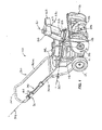
- a snow thrower 10 according to the invention may be of the walk-behind type illustrated in Fig. 1 .
- the snow thrower 10 may be self-propelled or pushed by the user, including a frame 11 supported by wheels 12 for movement over ground and an auger 13 supported by the frame 11.
- An engine 14 is mounted on the frame 11 and is operable to rotatably drive the auger 13.
- the downstream end of the outlet part 15 may be generally circular in cross section with a central longitudinal axis defining a pivot axis 21.
- the chute 20 may generally comprise a body 35 and deflector 23.
- the lower end of the body 35 may comprise a collar 24 to which an annular plate 25 is fixed, the collar 24 being complementary to and supported upon the outlet part 15, so as to pivot about the central pivot axis 21.
- the deflector 23 is pivotably coupled, as by fasteners 26, to the upper end of the body 35.
- a stream of snow exiting the outlet part 15 is deflected by inner surfaces 27 of the chute 20 (on the body 35 and deflector 23), and these surfaces 27 are inclined at an angle to the axis 21 which may be varied.
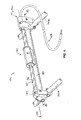
- a handle 30 used to steer the snow thrower 10 is connected to the frame 11 and may comprise a pair of parallel bar portions 30a, 30b extending lengthwise and joined by a transverse portion 30c.
- the handle 30 may support a chute actuator 31 which operates a mechanism to pivot the chute 20 about the pivot axis 21.
- the chute actuator 31 is an assembly mounted to the handle 30.
- the chute actuator 31 is connected by a Bowden cable 65 to a coupling assembly 33 which may be mounted to the outlet part 15.
- the Bowden cable 65 is curved, the first and second ends of the Bowden cable 65 having respective first and second longitudinal axes 34, 35 inclined to one another.
- the longitudinal axes 34, 35 may be coplanar or in different planes.
- the chute actuator 31 includes a shaft 36 having a first end 37, a second end 38 with a slot 39, and a lengthwise helical groove 65 in its outer surface.
- the shaft 36 is supported for rotation about the first axis 34, and a hand grip 41 is slidably supported by the handle 30 and operable to rotate the shaft 36.
- the hand grip 41 includes grip portions 42, 43 held together by fasteners 44.
- a rectangular member 45 is received in the grip portions 42, 43 and has a shaft-receiving opening 45 with an inwardly-extending projection 46.
- the shaft 36 is received through the rectangular member 90, and the projection 46 engages with the helical groove 65 to rotate the shaft 36 during sliding movement of the hand grip 41. Sliding engagement of the hand grip 41 with both the shaft 36 and handle section 30b prevents rotation of the hand grip 41.
- a first fixture 47 attaches to the handle 30 and is held in position by a fastener 48 and nut 49.
- a first bushing 50 is received within the fixture 47, and a journal bushing 48 is received within the first bushing 50.
- the bushing 48 receives and provides rotational support for the first end 37 of the shaft 36.
- the second end 38 of the shaft may be mounted to the handle by fixture parts 51, 52 clamped together as by fasteners 53 and nuts 54.
- the fixture parts 51, 52 have respective cavities 60 in which transverse grooves 61 are disposed.
- a hollow rotating coupler 55 (having an aperture 56 passing therethrough), a disc portion 57, and a square-shaped socket 58 are received between the fixture parts 51, 52.
- the disc portion 57 is received in the grooves 61 for rotation therein.
- a pin 62 passes through the aperture 56 and is received by the slot 39 in the shaft 36.
- the shaft 36 is received in the hollow rotating coupler 55 for rotation therewith.
- a bushing 63 is received in the cavities 60 of the fixture parts 51, 52 and receives and provides rotational support for the second end 38 of the shaft 36.
- the Bowden cable 65 is an assembly comprising an elongate flexible torsion member or cable 66 received within a flexible tubular sheath 67.
- the cable 66 may be a multi-stranded twisted or braided cable of substantially circular cross section.
- the sheath 67 may be formed of a helically coiled wire with a protective covering, with its opposing ends fixed to the chute actuator 31 and coupling assembly 33 so that the cable 66 is free to twist within the sheath 67.
- the length of the cable 66 between the chute actuator 31 and coupling assembly 33 is preferably enclosed in the sheath 67, which is thus generally longitudinally coextensive with the cable 66.
- the cable 66 may have a first end with a square-shaped protrusion 68 that passes through a first end collar 69 and is received in the square-shaped socket 58 of the coupler 55, the coupler 55 thus serving to transmit torque between the shaft 36 and the cable 66, while the collar 69 receives and locates the first end of the tubular sheath 67.
- the coupling assembly 33 connects and transmits torque between the second end of the cable 66 and the annular plate 25 of the chute 20.
- the coupling assembly 33 includes housing parts 70 mounted to the outlet part 15 and supporting a pinion 71 for rotation about axis 35. Longitudinal axis 35 of the second end of the cable 66 may intersect with the pivot axis 21, and extend perpendicular thereto.
- the second end of the flexible cable 66 has a square-shaped protrusion 72 received in a complementary square-shaped socket 73 of the driven pinion 71.
- a second collar 68 receives and locates the second end of the tubular sheath 67.
- a tooth set 77 comprises teeth 78 formed as between through-extending radial slots 79, which are meshed with the teeth 80 of the pinion 71.
- the snow thrower 10 may be steered by a user with the handle assembly 30 while walking behind the machine.
- the engine 14 rotatably drives the auger 13, which ejects snow from the outlet part 15.
- the chute 20 receives the snow from the outlet part 15.
- To direct the snow the chute 20 is oriented about the chute axis 21.
- Figs. 6-8 illustrate a first alternative embodiment of a chute actuator 131 for a snow thrower according to the invention, connected by a Bowden cable 65 to the coupling assembly 33 (not shown in Figs. 6-8 ).
- the chute actuator 131 is of generally like construction to the chute actuator 31 of Figs 1-5 , however instead of the shaft 36 extending parallel to one of the bar portions 30a, 30b, the shaft 36 extends transversely between bar portions 30a, 30b.
- the fixtures supporting the opposing ends of the shaft 36 also support a rail 80, extending parallel to the shaft 36 and. Sliding engagement of the hand grip 41 with both the rail 80 preventing rotation of the hand grip 41 about the shaft 36.
- Figs. 9-11 illustrate a second alternative embodiment of a chute actuator 231 for a snow thrower according to the invention connected by a Bowden cable 65 to the coupling assembly 33.
- a winder hand grip 85 mounted to rotate about the first longitudinal axis 34, is connected to the first end of the cable 66, such that rotation of the winder hand grip through a first angle turns the first end of the cable through the first angle to thereby pivot the chute.
- the winder hand grip assembly 85 includes an axle 86 mounted to pivot about the axis 34, and supported for rotation on a fixture comprising fixtures parts 87, 88 clamped together as by fasteners 89. Axially opposing ends of the axle 86 are fixed to rotate with the cable 66 and with a crank arm 90, as by complementary square or hexagonal interfaces respectively.
- a knob 91 pivotally mounted to the crank arm 90 is used to turn the crank arm 90.
- Figs. 12-14 show a third alternative embodiment of a chute actuator assembly 331 connected by a Bowden cable 65 to the coupling assembly 33.
- the actuator 331 may include a hand grip 95, and fixture parts 96, 97 for mounting the assembly to a selected portion of the handle such as longitudinal portion 30b.
- the fixtures 96, 97 may also cooperate to receive and locate the second end of the tubular sheath 67 held in a sleeve 68, as well as to provide abutment faces 103, 104 which abut the hand grip 95 to limit its angular travel.
- the hand grip 95 may be configured to pivot about a pivot axis 99 substantially transverse to the first axis 34, and may include a gear segment 100.
- a gear 101 meshed with the gear segment 100 is coupled to first end of the cable 66 for rotation with the cable about the first axis 34. In this manner, pivoting the hand grip 95 and attached gear segment 100 rotates the gear 101, thereby rotating the first end of the cable 66 about the first axis 34 in the manner of all the above described embodiments, to thereby turn the chute.
Landscapes
- Engineering & Computer Science (AREA)
- Architecture (AREA)
- Civil Engineering (AREA)
- Structural Engineering (AREA)
- Cleaning Of Streets, Tracks, Or Beaches (AREA)
- Transmission Devices (AREA)
- Chutes (AREA)
Applications Claiming Priority (1)
| Application Number | Priority Date | Filing Date | Title |
|---|---|---|---|
| US201161440167P | 2011-02-07 | 2011-02-07 |
Publications (3)
| Publication Number | Publication Date |
|---|---|
| EP2484835A2 true EP2484835A2 (de) | 2012-08-08 |
| EP2484835A3 EP2484835A3 (de) | 2014-06-18 |
| EP2484835B1 EP2484835B1 (de) | 2017-11-08 |
Family
ID=45656747
Family Applications (1)
| Application Number | Title | Priority Date | Filing Date |
|---|---|---|---|
| EP12250021.8A Active EP2484835B1 (de) | 2011-02-07 | 2012-02-07 | Mechanismus zur Steuerung des Abführblechs einer Schneefräse |
Country Status (6)
| Country | Link |
|---|---|
| US (1) | US9340938B2 (de) |
| EP (1) | EP2484835B1 (de) |
| CN (1) | CN202595689U (de) |
| CA (1) | CA2766746C (de) |
| DK (1) | DK2484835T3 (de) |
| NO (1) | NO2484835T3 (de) |
Cited By (1)
| Publication number | Priority date | Publication date | Assignee | Title |
|---|---|---|---|---|
| US10428477B2 (en) | 2017-08-09 | 2019-10-01 | Mtd Products Inc | Chute control assembly for a snow thrower |
Families Citing this family (6)
| Publication number | Priority date | Publication date | Assignee | Title |
|---|---|---|---|---|
| US9290897B2 (en) | 2014-02-03 | 2016-03-22 | Ariens Company | Snow thrower chute rotation mechanism |
| US9399846B2 (en) | 2014-11-19 | 2016-07-26 | The Toro Company | Snowthrower and chute rotation control mechanism for use with same |
| US9903079B2 (en) * | 2015-09-14 | 2018-02-27 | Briggs & Stratton Corporation | Snow thrower with electronic controls |
| CN206110068U (zh) | 2015-11-30 | 2017-04-19 | 南京德朔实业有限公司 | 扫雪机 |
| CN114127365A (zh) * | 2019-05-20 | 2022-03-01 | 创科无线普通合伙 | 扫雪机 |
| USD896282S1 (en) * | 2019-06-26 | 2020-09-15 | The Toro Company | Snow thrower housing |
Family Cites Families (29)
| Publication number | Priority date | Publication date | Assignee | Title |
|---|---|---|---|---|
| US46166A (en) * | 1865-01-31 | Improvement in universal shafting | ||
| US3509977A (en) * | 1967-05-01 | 1970-05-05 | Fmc Corp | Chute control mechanism |
| US3742626A (en) * | 1971-12-16 | 1973-07-03 | Atlas Tool & Mfg Co | Snow thrower |
| US3879866A (en) | 1973-03-05 | 1975-04-29 | Ralph R Gunderson | Mechanism for adjusting deflector for discharge chute of snow removal machine |
| US3921315A (en) | 1973-07-09 | 1975-11-25 | Eska Company | Snow blower safety chute |
| JPS53109332U (de) | 1977-02-09 | 1978-09-01 | ||
| US4205468A (en) * | 1978-10-27 | 1980-06-03 | Amf Incorporated | Remote control snow blower discharge chute deflector |
| US4667459A (en) | 1985-03-14 | 1987-05-26 | Roper Corporation | Two action control for power mowers |
| US4951403A (en) | 1987-07-20 | 1990-08-28 | Textron, Inc. | Single stage snowthrower |
| US4862607A (en) | 1988-10-03 | 1989-09-05 | Outboard Marine Corporation | Remote controlled snowthrower discharge chute deflector |
| US5221229A (en) * | 1991-10-18 | 1993-06-22 | Neil Brophy | Fish scaling apparatus |
| US5758436A (en) | 1996-02-22 | 1998-06-02 | Ariens Company | Single stage snowthrower |
| US5735064A (en) | 1996-05-21 | 1998-04-07 | Holl; Trygve A. | Operational control mechanism |
| US5820464A (en) * | 1997-01-03 | 1998-10-13 | S.S. White Technologies Inc. | Flexible shaft assembly |
| US6499238B2 (en) | 2000-03-01 | 2002-12-31 | Mtd Products Inc | Snow thrower with electric chute rotation and deflector control |
| JP3732391B2 (ja) | 2000-07-21 | 2006-01-05 | 本田技研工業株式会社 | 除雪機のシュータ構造 |
| US7032333B2 (en) | 2003-06-18 | 2006-04-25 | The Toro Company | Snowthrower chute and deflector control |
| US6931771B1 (en) | 2003-07-02 | 2005-08-23 | Clark Equipment Company | Fold-down chute for snow blower |
| WO2005075746A1 (ja) | 2004-02-06 | 2005-08-18 | Teruyoshi Umemura | 除雪機 |
| US20060207359A1 (en) * | 2004-05-28 | 2006-09-21 | Keith Kowalski | Compact linear/rotary actuator for offset actuation |
| US6952893B1 (en) | 2004-06-10 | 2005-10-11 | Mtd Products Inc | Chute retention device |
| US7093380B2 (en) * | 2004-10-21 | 2006-08-22 | Quadivator Inc. | Mounting of an accessory on an ATV |
| US7194827B2 (en) | 2004-10-26 | 2007-03-27 | Ariens Company | Snow thrower discharge chute |
| JP4394613B2 (ja) | 2005-07-29 | 2010-01-06 | 本田技研工業株式会社 | 除雪機 |
| US7347013B2 (en) | 2006-01-31 | 2008-03-25 | Ariens Company | Chute rotation and locking mechanism for snow thrower |
| US7472500B2 (en) | 2007-01-05 | 2009-01-06 | The Toro Company | Snowthrower deflector control |
| US7624521B2 (en) | 2007-01-05 | 2009-12-01 | The Toro Company | Snowthrower chute control |
| US7735246B2 (en) | 2008-03-10 | 2010-06-15 | Honda Motor Co., Ltd. | Snowblower chute controls and related methods |
| US7703223B2 (en) | 2008-05-29 | 2010-04-27 | Honda Motor Co., Ltd. | Motorized snowblower chute control assembly and related methods |
-
2012
- 2012-02-03 US US13/366,030 patent/US9340938B2/en not_active Expired - Fee Related
- 2012-02-06 CA CA2766746A patent/CA2766746C/en not_active Expired - Fee Related
- 2012-02-07 DK DK12250021.8T patent/DK2484835T3/en active
- 2012-02-07 NO NO12250021A patent/NO2484835T3/no unknown
- 2012-02-07 EP EP12250021.8A patent/EP2484835B1/de active Active
- 2012-02-07 CN CN201220038206XU patent/CN202595689U/zh not_active Expired - Lifetime
Non-Patent Citations (1)
| Title |
|---|
| None |
Cited By (3)
| Publication number | Priority date | Publication date | Assignee | Title |
|---|---|---|---|---|
| US10428477B2 (en) | 2017-08-09 | 2019-10-01 | Mtd Products Inc | Chute control assembly for a snow thrower |
| US20230082595A1 (en) | 2017-08-09 | 2023-03-16 | Mtd Products Inc | Chute control assembly for a snow thrower |
| US11993903B2 (en) | 2017-08-09 | 2024-05-28 | Mtd Products Inc | Chute control assembly for a snow thrower |
Also Published As
| Publication number | Publication date |
|---|---|
| EP2484835A3 (de) | 2014-06-18 |
| CA2766746A1 (en) | 2012-08-07 |
| US20120198732A1 (en) | 2012-08-09 |
| EP2484835B1 (de) | 2017-11-08 |
| NO2484835T3 (de) | 2018-04-07 |
| DK2484835T3 (en) | 2018-01-08 |
| CA2766746C (en) | 2020-06-09 |
| CN202595689U (zh) | 2012-12-12 |
| US9340938B2 (en) | 2016-05-17 |
Similar Documents
| Publication | Publication Date | Title |
|---|---|---|
| EP2484835B1 (de) | Mechanismus zur Steuerung des Abführblechs einer Schneefräse | |
| JP3808486B2 (ja) | ウォークビハインド型の動力機器用の速度制御システム | |
| EP1964977A2 (de) | Auswurfkanalrotationssystem und Betriebsverfahren dafür | |
| US11993903B2 (en) | Chute control assembly for a snow thrower | |
| US6301866B1 (en) | Vegetation trimming and edging device with adjustable head orientation | |
| DE602006000547T2 (de) | Drehgriffsteuerung-Vorrichtungen und Verfahren für eine selbstfahrende Mähmaschine | |
| US7305777B2 (en) | Auger for snow throw machine | |
| US20080190986A1 (en) | Electric Nailing Mechanism | |
| US9290897B2 (en) | Snow thrower chute rotation mechanism | |
| EP3381261B1 (de) | Bodenbearbeitungsgerät | |
| US20090107095A1 (en) | Variable speed transmission adjustable twist control apparatuses and methods for self-propelled mowing machine | |
| TW201720288A (zh) | 修枝剪 | |
| US5634379A (en) | Adjustable cable assembly | |
| EP2954977A1 (de) | Langhalsschleifer | |
| US5680748A (en) | Lawnmower cable control apparatus | |
| CN101325869B (zh) | 弯曲用配件及安装该弯曲用配件的便携式割草机 | |
| EP4376730A1 (de) | Chirurgisches instrument und lenkgetriebe dafür | |
| CA2589679A1 (en) | Combination yard maintenance apparatus | |
| JP2007045528A (ja) | カンオープナー | |
| CN104066642B (zh) | 具有缆线转向组件的庭院维护车 | |
| EP3506730B1 (de) | Handgeführte arbeitsmaschine | |
| SE1951013A1 (en) | Bucket height control system | |
| KR100262713B1 (ko) | 동력 손수레 | |
| CN114190153A (zh) | 一种操控机构及割草机 | |
| RU53742U1 (ru) | Вязальное устройство |
Legal Events
| Date | Code | Title | Description |
|---|---|---|---|
| PUAI | Public reference made under article 153(3) epc to a published international application that has entered the european phase |
Free format text: ORIGINAL CODE: 0009012 |
|
| AK | Designated contracting states |
Kind code of ref document: A2 Designated state(s): AL AT BE BG CH CY CZ DE DK EE ES FI FR GB GR HR HU IE IS IT LI LT LU LV MC MK MT NL NO PL PT RO RS SE SI SK SM TR |
|
| AX | Request for extension of the european patent |
Extension state: BA ME |
|
| PUAL | Search report despatched |
Free format text: ORIGINAL CODE: 0009013 |
|
| AK | Designated contracting states |
Kind code of ref document: A3 Designated state(s): AL AT BE BG CH CY CZ DE DK EE ES FI FR GB GR HR HU IE IS IT LI LT LU LV MC MK MT NL NO PL PT RO RS SE SI SK SM TR |
|
| AX | Request for extension of the european patent |
Extension state: BA ME |
|
| RIC1 | Information provided on ipc code assigned before grant |
Ipc: E01H 5/04 20060101AFI20140515BHEP |
|
| 17P | Request for examination filed |
Effective date: 20141217 |
|
| RBV | Designated contracting states (corrected) |
Designated state(s): AL AT BE BG CH CY CZ DE DK EE ES FI FR GB GR HR HU IE IS IT LI LT LU LV MC MK MT NL NO PL PT RO RS SE SI SK SM TR |
|
| 17Q | First examination report despatched |
Effective date: 20160915 |
|
| RIC1 | Information provided on ipc code assigned before grant |
Ipc: E01H 5/04 20060101AFI20170412BHEP Ipc: E01H 5/09 20060101ALI20170412BHEP |
|
| GRAP | Despatch of communication of intention to grant a patent |
Free format text: ORIGINAL CODE: EPIDOSNIGR1 |
|
| INTG | Intention to grant announced |
Effective date: 20170524 |
|
| GRAS | Grant fee paid |
Free format text: ORIGINAL CODE: EPIDOSNIGR3 |
|
| GRAA | (expected) grant |
Free format text: ORIGINAL CODE: 0009210 |
|
| AK | Designated contracting states |
Kind code of ref document: B1 Designated state(s): AL AT BE BG CH CY CZ DE DK EE ES FI FR GB GR HR HU IE IS IT LI LT LU LV MC MK MT NL NO PL PT RO RS SE SI SK SM TR |
|
| REG | Reference to a national code |
Ref country code: GB Ref legal event code: FG4D |
|
| REG | Reference to a national code |
Ref country code: CH Ref legal event code: EP Ref country code: AT Ref legal event code: REF Ref document number: 944281 Country of ref document: AT Kind code of ref document: T Effective date: 20171115 |
|
| REG | Reference to a national code |
Ref country code: IE Ref legal event code: FG4D |
|
| REG | Reference to a national code |
Ref country code: DE Ref legal event code: R096 Ref document number: 602012039445 Country of ref document: DE |
|
| REG | Reference to a national code |
Ref country code: DK Ref legal event code: T3 Effective date: 20180103 |
|
| REG | Reference to a national code |
Ref country code: SE Ref legal event code: TRGR |
|
| REG | Reference to a national code |
Ref country code: NL Ref legal event code: MP Effective date: 20171108 |
|
| REG | Reference to a national code |
Ref country code: LT Ref legal event code: MG4D |
|
| REG | Reference to a national code |
Ref country code: AT Ref legal event code: MK05 Ref document number: 944281 Country of ref document: AT Kind code of ref document: T Effective date: 20171108 |
|
| REG | Reference to a national code |
Ref country code: NO Ref legal event code: T2 Effective date: 20171108 |
|
| PG25 | Lapsed in a contracting state [announced via postgrant information from national office to epo] |
Ref country code: LT Free format text: LAPSE BECAUSE OF FAILURE TO SUBMIT A TRANSLATION OF THE DESCRIPTION OR TO PAY THE FEE WITHIN THE PRESCRIBED TIME-LIMIT Effective date: 20171108 Ref country code: ES Free format text: LAPSE BECAUSE OF FAILURE TO SUBMIT A TRANSLATION OF THE DESCRIPTION OR TO PAY THE FEE WITHIN THE PRESCRIBED TIME-LIMIT Effective date: 20171108 Ref country code: NL Free format text: LAPSE BECAUSE OF FAILURE TO SUBMIT A TRANSLATION OF THE DESCRIPTION OR TO PAY THE FEE WITHIN THE PRESCRIBED TIME-LIMIT Effective date: 20171108 |
|
| PG25 | Lapsed in a contracting state [announced via postgrant information from national office to epo] |
Ref country code: BG Free format text: LAPSE BECAUSE OF FAILURE TO SUBMIT A TRANSLATION OF THE DESCRIPTION OR TO PAY THE FEE WITHIN THE PRESCRIBED TIME-LIMIT Effective date: 20180208 Ref country code: HR Free format text: LAPSE BECAUSE OF FAILURE TO SUBMIT A TRANSLATION OF THE DESCRIPTION OR TO PAY THE FEE WITHIN THE PRESCRIBED TIME-LIMIT Effective date: 20171108 Ref country code: RS Free format text: LAPSE BECAUSE OF FAILURE TO SUBMIT A TRANSLATION OF THE DESCRIPTION OR TO PAY THE FEE WITHIN THE PRESCRIBED TIME-LIMIT Effective date: 20171108 Ref country code: AT Free format text: LAPSE BECAUSE OF FAILURE TO SUBMIT A TRANSLATION OF THE DESCRIPTION OR TO PAY THE FEE WITHIN THE PRESCRIBED TIME-LIMIT Effective date: 20171108 Ref country code: GR Free format text: LAPSE BECAUSE OF FAILURE TO SUBMIT A TRANSLATION OF THE DESCRIPTION OR TO PAY THE FEE WITHIN THE PRESCRIBED TIME-LIMIT Effective date: 20180209 Ref country code: LV Free format text: LAPSE BECAUSE OF FAILURE TO SUBMIT A TRANSLATION OF THE DESCRIPTION OR TO PAY THE FEE WITHIN THE PRESCRIBED TIME-LIMIT Effective date: 20171108 |
|
| PG25 | Lapsed in a contracting state [announced via postgrant information from national office to epo] |
Ref country code: CY Free format text: LAPSE BECAUSE OF FAILURE TO SUBMIT A TRANSLATION OF THE DESCRIPTION OR TO PAY THE FEE WITHIN THE PRESCRIBED TIME-LIMIT Effective date: 20171108 Ref country code: EE Free format text: LAPSE BECAUSE OF FAILURE TO SUBMIT A TRANSLATION OF THE DESCRIPTION OR TO PAY THE FEE WITHIN THE PRESCRIBED TIME-LIMIT Effective date: 20171108 Ref country code: CZ Free format text: LAPSE BECAUSE OF FAILURE TO SUBMIT A TRANSLATION OF THE DESCRIPTION OR TO PAY THE FEE WITHIN THE PRESCRIBED TIME-LIMIT Effective date: 20171108 Ref country code: SK Free format text: LAPSE BECAUSE OF FAILURE TO SUBMIT A TRANSLATION OF THE DESCRIPTION OR TO PAY THE FEE WITHIN THE PRESCRIBED TIME-LIMIT Effective date: 20171108 |
|
| REG | Reference to a national code |
Ref country code: DE Ref legal event code: R097 Ref document number: 602012039445 Country of ref document: DE |
|
| PG25 | Lapsed in a contracting state [announced via postgrant information from national office to epo] |
Ref country code: SM Free format text: LAPSE BECAUSE OF FAILURE TO SUBMIT A TRANSLATION OF THE DESCRIPTION OR TO PAY THE FEE WITHIN THE PRESCRIBED TIME-LIMIT Effective date: 20171108 Ref country code: IT Free format text: LAPSE BECAUSE OF FAILURE TO SUBMIT A TRANSLATION OF THE DESCRIPTION OR TO PAY THE FEE WITHIN THE PRESCRIBED TIME-LIMIT Effective date: 20171108 Ref country code: RO Free format text: LAPSE BECAUSE OF FAILURE TO SUBMIT A TRANSLATION OF THE DESCRIPTION OR TO PAY THE FEE WITHIN THE PRESCRIBED TIME-LIMIT Effective date: 20171108 Ref country code: PL Free format text: LAPSE BECAUSE OF FAILURE TO SUBMIT A TRANSLATION OF THE DESCRIPTION OR TO PAY THE FEE WITHIN THE PRESCRIBED TIME-LIMIT Effective date: 20171108 |
|
| PLBE | No opposition filed within time limit |
Free format text: ORIGINAL CODE: 0009261 |
|
| REG | Reference to a national code |
Ref country code: CH Ref legal event code: PL |
|
| STAA | Information on the status of an ep patent application or granted ep patent |
Free format text: STATUS: NO OPPOSITION FILED WITHIN TIME LIMIT |
|
| PG25 | Lapsed in a contracting state [announced via postgrant information from national office to epo] |
Ref country code: MC Free format text: LAPSE BECAUSE OF FAILURE TO SUBMIT A TRANSLATION OF THE DESCRIPTION OR TO PAY THE FEE WITHIN THE PRESCRIBED TIME-LIMIT Effective date: 20171108 |
|
| 26N | No opposition filed |
Effective date: 20180809 |
|
| REG | Reference to a national code |
Ref country code: IE Ref legal event code: MM4A |
|
| REG | Reference to a national code |
Ref country code: BE Ref legal event code: MM Effective date: 20180228 |
|
| PG25 | Lapsed in a contracting state [announced via postgrant information from national office to epo] |
Ref country code: LI Free format text: LAPSE BECAUSE OF NON-PAYMENT OF DUE FEES Effective date: 20180228 Ref country code: LU Free format text: LAPSE BECAUSE OF NON-PAYMENT OF DUE FEES Effective date: 20180207 Ref country code: CH Free format text: LAPSE BECAUSE OF NON-PAYMENT OF DUE FEES Effective date: 20180228 Ref country code: SI Free format text: LAPSE BECAUSE OF FAILURE TO SUBMIT A TRANSLATION OF THE DESCRIPTION OR TO PAY THE FEE WITHIN THE PRESCRIBED TIME-LIMIT Effective date: 20171108 |
|
| REG | Reference to a national code |
Ref country code: FR Ref legal event code: ST Effective date: 20181031 |
|
| PG25 | Lapsed in a contracting state [announced via postgrant information from national office to epo] |
Ref country code: IE Free format text: LAPSE BECAUSE OF NON-PAYMENT OF DUE FEES Effective date: 20180207 |
|
| PG25 | Lapsed in a contracting state [announced via postgrant information from national office to epo] |
Ref country code: BE Free format text: LAPSE BECAUSE OF NON-PAYMENT OF DUE FEES Effective date: 20180228 Ref country code: FR Free format text: LAPSE BECAUSE OF NON-PAYMENT OF DUE FEES Effective date: 20180228 |
|
| PG25 | Lapsed in a contracting state [announced via postgrant information from national office to epo] |
Ref country code: MT Free format text: LAPSE BECAUSE OF NON-PAYMENT OF DUE FEES Effective date: 20180207 |
|
| PG25 | Lapsed in a contracting state [announced via postgrant information from national office to epo] |
Ref country code: TR Free format text: LAPSE BECAUSE OF FAILURE TO SUBMIT A TRANSLATION OF THE DESCRIPTION OR TO PAY THE FEE WITHIN THE PRESCRIBED TIME-LIMIT Effective date: 20171108 |
|
| PG25 | Lapsed in a contracting state [announced via postgrant information from national office to epo] |
Ref country code: HU Free format text: LAPSE BECAUSE OF FAILURE TO SUBMIT A TRANSLATION OF THE DESCRIPTION OR TO PAY THE FEE WITHIN THE PRESCRIBED TIME-LIMIT; INVALID AB INITIO Effective date: 20120207 Ref country code: PT Free format text: LAPSE BECAUSE OF FAILURE TO SUBMIT A TRANSLATION OF THE DESCRIPTION OR TO PAY THE FEE WITHIN THE PRESCRIBED TIME-LIMIT Effective date: 20171108 |
|
| PG25 | Lapsed in a contracting state [announced via postgrant information from national office to epo] |
Ref country code: MK Free format text: LAPSE BECAUSE OF NON-PAYMENT OF DUE FEES Effective date: 20171108 |
|
| PG25 | Lapsed in a contracting state [announced via postgrant information from national office to epo] |
Ref country code: AL Free format text: LAPSE BECAUSE OF FAILURE TO SUBMIT A TRANSLATION OF THE DESCRIPTION OR TO PAY THE FEE WITHIN THE PRESCRIBED TIME-LIMIT Effective date: 20171108 |
|
| PGFP | Annual fee paid to national office [announced via postgrant information from national office to epo] |
Ref country code: DE Payment date: 20250227 Year of fee payment: 14 Ref country code: IS Payment date: 20250120 Year of fee payment: 14 |
|
| PGFP | Annual fee paid to national office [announced via postgrant information from national office to epo] |
Ref country code: DK Payment date: 20250225 Year of fee payment: 14 Ref country code: FI Payment date: 20250225 Year of fee payment: 14 |
|
| PGFP | Annual fee paid to national office [announced via postgrant information from national office to epo] |
Ref country code: SE Payment date: 20250227 Year of fee payment: 14 |
|
| PGFP | Annual fee paid to national office [announced via postgrant information from national office to epo] |
Ref country code: NO Payment date: 20250227 Year of fee payment: 14 |
|
| PGFP | Annual fee paid to national office [announced via postgrant information from national office to epo] |
Ref country code: GB Payment date: 20250227 Year of fee payment: 14 |