EP2483573B1 - Straddle carrier for use in container terminals and for other transport purposes - Google Patents
Straddle carrier for use in container terminals and for other transport purposes Download PDFInfo
- Publication number
- EP2483573B1 EP2483573B1 EP10765373.5A EP10765373A EP2483573B1 EP 2483573 B1 EP2483573 B1 EP 2483573B1 EP 10765373 A EP10765373 A EP 10765373A EP 2483573 B1 EP2483573 B1 EP 2483573B1
- Authority
- EP
- European Patent Office
- Prior art keywords
- straddle carrier
- carrier according
- spring
- frame
- hoisting
- Prior art date
- Legal status (The legal status is an assumption and is not a legal conclusion. Google has not performed a legal analysis and makes no representation as to the accuracy of the status listed.)
- Active
Links
- 238000013016 damping Methods 0.000 claims description 9
- 238000001514 detection method Methods 0.000 claims description 8
- 239000000969 carrier Substances 0.000 claims description 3
- 239000002184 metal Substances 0.000 claims description 3
- 239000004744 fabric Substances 0.000 claims description 2
- 230000007423 decrease Effects 0.000 description 1
- 238000010586 diagram Methods 0.000 description 1
- 230000001788 irregular Effects 0.000 description 1
- 238000012423 maintenance Methods 0.000 description 1
- 239000000463 material Substances 0.000 description 1
- 230000036316 preload Effects 0.000 description 1
- 239000000725 suspension Substances 0.000 description 1
Images

Classifications
-
- F—MECHANICAL ENGINEERING; LIGHTING; HEATING; WEAPONS; BLASTING
- F16—ENGINEERING ELEMENTS AND UNITS; GENERAL MEASURES FOR PRODUCING AND MAINTAINING EFFECTIVE FUNCTIONING OF MACHINES OR INSTALLATIONS; THERMAL INSULATION IN GENERAL
- F16F—SPRINGS; SHOCK-ABSORBERS; MEANS FOR DAMPING VIBRATION
- F16F1/00—Springs
- F16F1/36—Springs made of rubber or other material having high internal friction, e.g. thermoplastic elastomers
- F16F1/362—Springs made of rubber or other material having high internal friction, e.g. thermoplastic elastomers made of steel wool, compressed hair, woven or non-woven textile, or like materials
-
- B—PERFORMING OPERATIONS; TRANSPORTING
- B66—HOISTING; LIFTING; HAULING
- B66C—CRANES; LOAD-ENGAGING ELEMENTS OR DEVICES FOR CRANES, CAPSTANS, WINCHES, OR TACKLES
- B66C13/00—Other constructional features or details
- B66C13/04—Auxiliary devices for controlling movements of suspended loads, or preventing cable slack
- B66C13/06—Auxiliary devices for controlling movements of suspended loads, or preventing cable slack for minimising or preventing longitudinal or transverse swinging of loads
-
- B—PERFORMING OPERATIONS; TRANSPORTING
- B66—HOISTING; LIFTING; HAULING
- B66C—CRANES; LOAD-ENGAGING ELEMENTS OR DEVICES FOR CRANES, CAPSTANS, WINCHES, OR TACKLES
- B66C13/00—Other constructional features or details
- B66C13/04—Auxiliary devices for controlling movements of suspended loads, or preventing cable slack
- B66C13/10—Auxiliary devices for controlling movements of suspended loads, or preventing cable slack for preventing cable slack
- B66C13/105—Auxiliary devices for controlling movements of suspended loads, or preventing cable slack for preventing cable slack electrical
-
- B—PERFORMING OPERATIONS; TRANSPORTING
- B66—HOISTING; LIFTING; HAULING
- B66C—CRANES; LOAD-ENGAGING ELEMENTS OR DEVICES FOR CRANES, CAPSTANS, WINCHES, OR TACKLES
- B66C13/00—Other constructional features or details
- B66C13/16—Applications of indicating, registering, or weighing devices
-
- B—PERFORMING OPERATIONS; TRANSPORTING
- B66—HOISTING; LIFTING; HAULING
- B66C—CRANES; LOAD-ENGAGING ELEMENTS OR DEVICES FOR CRANES, CAPSTANS, WINCHES, OR TACKLES
- B66C19/00—Cranes comprising trolleys or crabs running on fixed or movable bridges or gantries
- B66C19/007—Cranes comprising trolleys or crabs running on fixed or movable bridges or gantries for containers
-
- B—PERFORMING OPERATIONS; TRANSPORTING
- B66—HOISTING; LIFTING; HAULING
- B66D—CAPSTANS; WINCHES; TACKLES, e.g. PULLEY BLOCKS; HOISTS
- B66D1/00—Rope, cable, or chain winding mechanisms; Capstans
- B66D1/26—Rope, cable, or chain winding mechanisms; Capstans having several drums or barrels
-
- F—MECHANICAL ENGINEERING; LIGHTING; HEATING; WEAPONS; BLASTING
- F16—ENGINEERING ELEMENTS AND UNITS; GENERAL MEASURES FOR PRODUCING AND MAINTAINING EFFECTIVE FUNCTIONING OF MACHINES OR INSTALLATIONS; THERMAL INSULATION IN GENERAL
- F16F—SPRINGS; SHOCK-ABSORBERS; MEANS FOR DAMPING VIBRATION
- F16F3/00—Spring units consisting of several springs, e.g. for obtaining a desired spring characteristic
- F16F3/08—Spring units consisting of several springs, e.g. for obtaining a desired spring characteristic with springs made of a material having high internal friction, e.g. rubber
Definitions
- the invention relates to a straddle carrier for use in container terminals and for other transport tasks, with a frame, a load suspension device that hangs between the frame and can be locked with a container, carriers that are arranged at the lower region of the frame and each a variety in have a row of arranged wheels, and hoisting winches, by means of which hoisting ropes can be rolled up and unrolled, which are attached to the hoisting winches at one end and are guided by means of lifting rope bearing points on the load-carrying means and frame side.
- the invention is based on the object of developing the gantry pallet truck described at the outset for use in container terminals and for other transport tasks in such a way that the mechanical loads to be absorbed by its lifting ropes are considerably reduced.
- This object is achieved with a comparatively low mechanical and structural outlay in that a spring device is arranged on at least one hoist rope bearing point of each hoist rope of the gantry lifting truck, by means of which load impacts transmitted to the hoist ropes can be damped.
- the load peaks of each mechanical load on the hoisting ropes are absorbed by means of the spring device assigned to the respective hoisting rope, with the result that the lifespan of the hoisting ropes is considerably increased or that - with the same planned lifespan - the technical requirements for the lifting ropes can be reduced.
- a spring device is assigned to a fixed point bearing of the lifting rope on the frame side.
- embodiments according to the invention are also expedient in which a spring device is assigned to a deflecting roller bearing of the lifting rope on the frame side.
- the spring devices have a load cell, by means of which the height of load impacts exerted on the lifting rope can be determined, it can be stored for each lifting rope what mechanical stresses it is subjected to has been. This enables maintenance and / or replacement intervals to be optimized.
- the straddle carrier According to a further advantageous embodiment of the straddle carrier according to the invention, its spring devices have a slack rope detection device, by means of which the slackening of the respective lifting rope can be detected.
- irregular operating states are automatically ascertained in which a load to be transported by means of the straddle carrier is not carried by all lifting ropes.
- the slack rope detection device advantageously has two plate elements that are prestressed away from one another and whose distance can be measured.
- the pre-tensioned plate elements are pressed towards each other by the loads acting on the hoist rope against the spring preload, and in the event that there is no load on the hoist rope, the distance between the two plate elements exceeds a predeterminable maximum distance, from which a slack hoist rope is indicated by means of the slack rope detection device Signal is generated.
- a damping unit of the spring device which actually serves to reduce the mechanical stress advantageously has two spring elements arranged one behind the other in the load direction of the lifting cable.
- the spring elements can be separated from one another by means of an intermediate plate, so that the deformations to be absorbed by the spring elements are distributed as evenly as possible over the entire damping unit.
- the spring elements of the damping device made of a metal mesh body or the like are advantageous. formed, which on the one hand has the robustness required for the operation of the spring devices and on the other hand has elastic restoring forces which enable a long service life for the spring device.
- a straddle carrier 1 which is explained in more detail below, has a frame 2, to which an upper frame 3 belongs, from which four vertical supports 4 extend downward.
- the vertical supports 4 are arranged approximately at the corners of the rectangular upper frame 3.
- a travel carrier 5 is attached to both sides of the straddle carrier 1, of which in Figure 1 only one is visible.
- the frame 2 connects the two chassis 5 in the manner of a portal.
- a load-carrying device for example a spreader 6, is provided, which is arranged between the vertical supports 4 of the frame 2 assigned to the two driving beams 5.
- the spreader 6 can be connected or locked to a container 8 by suitable connecting means 7.
- the spreader 6 is in the in Figure 1 Embodiment of the portal truck 1 shown on the upper frame 3 of the frame 2 provided lifting jacks 9 between the vertical supports 4 of the frame 2 can be raised and lowered vertically.
- the spreader 6 is suspended from the hoisting winches 9 by means of hoisting ropes 10, which are each attached to the hoisting winches 9 at one end and are guided by hoisting rope bearing points 11, 12, 13 on the spreader and frame side.
- a driver's cabin 14 is provided on the upper frame 3 of the frame 2, from which an operator of the straddle carrier 1 can drive and control the straddle 6 and the spreader 6.
- the hoist rope bearings 11, 12, 13 are designed as spreading-side deflection roller bearings 11, frame-side fixed point bearings 12 and frame-side deflection roller bearings 13.
- Figure 1 results in that in the Figure 1 left hoist rope 10 from the hoist winch 9 to the spreading-side deflection roller bearing 11 and back from there led to the fixed point bearing 12 on the frame side.
- Figure 1 Right hoist rope 10 runs from the hoist 9 to the frame-side deflection roller bearing 13, from there to the spreader-side deflection roller bearing 11 and then back to the frame-side fixed point bearing 12.
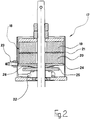
- Each hoist rope 10 is a hoist rope bearing point 11, 12 or 13 in Figure 2 shown spring device 17 associated.
- spring device 17 load surges occurring during operation of the portal lifting truck 1 or the spreader 6 are damped, so that the corresponding mechanical stresses on the lifting ropes 10 are reduced.
- the spring device 17 in the exemplary embodiment shown has a damping unit 18 which has two spring elements 19, 20 arranged one behind the other in the direction of loading of the lifting cable 10.
- the two spring elements 19, 20 are separated from one another by an intermediate plate 21.
- the latter is absorbed in substantial parts by means of the two spring elements 19, 20 which deform.
- the stress on the hoisting rope 10 is reduced accordingly.
- the spring elements 19, 20 of the damping unit 18 return to their original shape due to their restoring forces.
- the spring device 17 in the in Figure 2 shows a load cell 22, by means of which a load impact exerted on the lifting rope 10, ie the force exerted on the lifting rope 10 and in the spring device 17 stored force due to the deformation of the spring elements 19, 20 can be detected.
- the spring device 17 in in Figure 2 Embodiment shown a slack rope detection device 23, by means of which it can be determined when the hoisting rope 10 is free of load.
- the slack rope detection device 23 has a plate element 24 on the damping unit side and a plate element 25 on the load cell side, which are pretensioned away from one another by a separating spring 26. As soon as the distance between the two plate elements 24, 25 exceeds a predeterminable value, a corresponding signal can be generated by means of the slack rope detection device 23, by means of which it is communicated that the lifting rope 10 is load-free.
- the load cell 22 may generate signals indicating the respective level of a load surge and to forward them to a suitable control device.
- the two spring elements 19, 20 of the damping unit 18 of the spring device 17 are made of a robust material with an elasticity module suitable for corresponding loads.
- metal fabric bodies can be used for the spring elements 19, 20.
Description
Die Erfindung bezieht sich auf einen Portalhubwagen zum Einsatz in Containerterminals und für andere Transportaufgaben, mit einem Rahmengestell, einem Lastaufnahmemittel, das zwischen dem Rahmengestell hängt und mit einem Container verriegelbar ist, Fahrträgern, die am unteren Bereich des Rahmengestells angeordnet sind und jeweils eine Vielzahl in einer Reihe angeordneter Räder aufweisen, und Hubwinden, mittels denen Hubseile auf- und abrollbar sind, die mit einem Ende an den Hubwinden angebracht und mittels lastaufnahmemittel- und rahmengestellseitiger Hubseillagerpunkte geführt sind.The invention relates to a straddle carrier for use in container terminals and for other transport tasks, with a frame, a load suspension device that hangs between the frame and can be locked with a container, carriers that are arranged at the lower region of the frame and each a variety in have a row of arranged wheels, and hoisting winches, by means of which hoisting ropes can be rolled up and unrolled, which are attached to the hoisting winches at one end and are guided by means of lifting rope bearing points on the load-carrying means and frame side.
Im Betrieb derartiger Portalhubwagen werden deren Hubseile starken mechanischen Beanspruchungen unterzogen. Entsprechende Laststöße treten insbesondere bei Lastaufnahmen und bei bestimmten Fahrmanövern, insbesondere bei Brems- und Beschleunigungsvorgängen, auf.
Der Erfindung liegt die Aufgabe zugrunde, den eingangs geschilderten Portalhubwagen zum Einsatz in Containerterminals und für andere Transportaufgaben derart weiterzubilden, dass die von seinen Hubseilen aufzunehmenden mechanischen Beanspruchungen erheblich reduziert werden.The invention is based on the object of developing the gantry pallet truck described at the outset for use in container terminals and for other transport tasks in such a way that the mechanical loads to be absorbed by its lifting ropes are considerably reduced.
Diese Aufgabe wird mit einem vergleichsweise geringen mechanisch-konstruktiven Aufwand dadurch gelöst, dass an zumindest einem Hubseillagerpunkt jedes Hubseils des Portalhubwagens eine Federeinrichtung angeordnet ist, mittels der auf die Hubseile übertragene Laststöße dämpfbar sind. Die Lastspitzen jeder mechanischen Beanspruchung der Hubseile werden erfindungsgemäß mittels der dem jeweiligen Hubseil zugeordneten Federeinrichtung aufgenommen, mit der Folge, dass die Lebensdauer der Hubseile erheblich erhöht ist bzw. dass - bei gleicher geplanter Lebensdauer - die technischen Anforderungen an die Hubseile reduziert werden können.This object is achieved with a comparatively low mechanical and structural outlay in that a spring device is arranged on at least one hoist rope bearing point of each hoist rope of the gantry lifting truck, by means of which load impacts transmitted to the hoist ropes can be damped. According to the invention, the load peaks of each mechanical load on the hoisting ropes are absorbed by means of the spring device assigned to the respective hoisting rope, with the result that the lifespan of the hoisting ropes is considerably increased or that - with the same planned lifespan - the technical requirements for the lifting ropes can be reduced.
Gemäß einer vorteilhaften Ausführungsform des erfindungsgemäßen Portalhubwagens ist einem rahmengestellseitigen Festpunktlager des Hubseils eine Federeinrichtung zugeordnet.According to an advantageous embodiment of the straddle carrier according to the invention, a spring device is assigned to a fixed point bearing of the lifting rope on the frame side.
Alternativ oder zusätzlich ist es möglich, einem lastaufnahmemittelseitigen Umlenkrollenlager des Hubseils eine Federeinrichtung zuzuordnen.Alternatively or additionally, it is possible to assign a spring device to a deflecting roller bearing of the lifting cable on the load-carrying means side.
Schließlich sind auch erfindungsgemäße Ausführungsformen zweckmäßig, bei denen einem rahmengestellseitigen Umlenkrollenlager des Hubseils eine Federeinrichtung zugeordnet ist.Finally, embodiments according to the invention are also expedient in which a spring device is assigned to a deflecting roller bearing of the lifting rope on the frame side.
Sofern die Federeinrichtungen eine Kraftmessdose aufweisen, mittels der die Höhe von auf das Hubseil ausgeübten Laststößen ermittelbar ist, kann für jedes Hubseil abgespeichert werden, welchen mechanischen Beanspruchungen es unterzogen worden ist. Hierdurch können Wartungs- und/oder Austauschintervalle optimiert werden.If the spring devices have a load cell, by means of which the height of load impacts exerted on the lifting rope can be determined, it can be stored for each lifting rope what mechanical stresses it is subjected to has been. This enables maintenance and / or replacement intervals to be optimized.
Gemäß einer weiteren vorteilhaften Ausführungsform des erfindungsgemäßen Portalhubwagens weisen dessen Federeinrichtungen eine Schlaffseilerkennungseinrichtung auf, mittels der eine Erschlaffung des jeweiligen Hubseils erfassbar ist. Hierdurch werden automatisch irreguläre Betriebszustände erfassbar, bei denen eine mittels des Portalhubwagens zu transportierende Last nicht von allen Hubseilen getragen wird.According to a further advantageous embodiment of the straddle carrier according to the invention, its spring devices have a slack rope detection device, by means of which the slackening of the respective lifting rope can be detected. As a result, irregular operating states are automatically ascertained in which a load to be transported by means of the straddle carrier is not carried by all lifting ropes.
Hierzu weist die Schlaffseilerkennungseinrichtung vorteilhaft zwei voneinander weg vorgespannte Plattenelemente auf, deren Abstand messbar ist. Üblicherweise werden die vorgespannten Plattenelemente durch die am Hubseil angreifenden Lasten gegen die Federvorspannung aufeinander zu gedrückt, wobei für den Fall, dass keine Last am Hubseil ist, der Abstand der beiden Plattenelemente einen vorgebbaren Maximalabstand überschreitet, ab dem mittels der Schlaffseilerkennungseinrichtung ein ein schlaffes Hubseil anzeigendes Signal generiert wird.For this purpose, the slack rope detection device advantageously has two plate elements that are prestressed away from one another and whose distance can be measured. Usually, the pre-tensioned plate elements are pressed towards each other by the loads acting on the hoist rope against the spring preload, and in the event that there is no load on the hoist rope, the distance between the two plate elements exceeds a predeterminable maximum distance, from which a slack hoist rope is indicated by means of the slack rope detection device Signal is generated.
Eine der eigentlichen Reduzierung der mechanischen Beanspruchung dienende Dämpfungseinheit der Federeinrichtung hat vorteilhaft zwei in Lastrichtung des Hubseils hintereinander angeordnete Federelemente. Die Federelemente können mittels einer Zwischenplatte voneinander getrennt sein, so dass die mittels der Federelemente aufzunehmenden Verformungen möglichst gleichmäßig auf die gesamte Dämpfungseinheit verteilt werden.A damping unit of the spring device which actually serves to reduce the mechanical stress advantageously has two spring elements arranged one behind the other in the load direction of the lifting cable. The spring elements can be separated from one another by means of an intermediate plate, so that the deformations to be absorbed by the spring elements are distributed as evenly as possible over the entire damping unit.
Vorteilhaft sind die Federelemente der Dämpfungseinrichtung aus einem Metallgewebekörper od.dgl. ausgebildet, der einerseits über die für den Betrieb der Federeinrichtungen erforderliche Robustheit verfügt und andererseits elastische Rückstellkräfte aufweist, die für die Federeinrichtung eine lange Lebensdauer ermöglichen.The spring elements of the damping device made of a metal mesh body or the like are advantageous. formed, which on the one hand has the robustness required for the operation of the spring devices and on the other hand has elastic restoring forces which enable a long service life for the spring device.
Im Folgenden wird die Erfindung anhand einer Ausführungsform unter Bezugnahme auf die Zeichnung näher erläutert.The invention is explained in more detail below using an embodiment with reference to the drawing.
Es zeigen:
Figur 1- eine Prinzipdarstellung eines erfindungsgemäßen Portalhubwagens (Straddle Carrier); und
Figur 2- eine Darstellung einer Ausführungsform einer Federeinrichtung des in
Figur 1
- Figure 1
- a schematic diagram of a straddle carrier according to the invention; and
- Figure 2
- a representation of an embodiment of a spring device of the in
Figure 1 Portal lift truck according to the invention shown.
Eine anhand der
An den oberrahmenfernen unteren Enden der an einer Längsseite des Oberrahmens 3 angeordneten beiden vertikalen Stützen 4 ist an beiden Seiten des Portalhubwagens 1 jeweils ein Fahrträger 5 angebracht, von denen in
Am Portalhubwagen 1 ist ein Lastaufnahmemittel, z.B. ein Spreader 6 vorgesehen, der zwischen den den beiden Fahrträgern 5 zugeordneten vertikalen Stützen 4 des Rahmengestells 2 angeordnet ist. Der Spreader 6 ist durch geeignete Verbindungsmittel 7 mit einem Container 8 verbind- bzw. verriegelbar. Des Weiteren ist der Spreader 6 mittels in der in
Hierzu ist der Spreader 6 mittels Hubseilen 10, die mit jeweils einem Ende an den Hubwinden 9 befestigt sind und mittels spreader- und rahmengestellseitigen Hubseillagerpunkten 11, 12, 13 geführt sind, an den Hubwinden 9 aufgehängt.For this purpose, the
Am Oberrahmen 3 des Rahmengestells 2 ist eine Fahrerkabine 14 vorgesehen, aus der heraus eine Bedienungsperson des Portalhubwagens 1 diesen und den Spreader 6 fahren bzw. steuern kann. Die beiden Fahrträger 9 des Portalhubwagens 1, von denen in
Im dargestellten Ausführungsbeispiel des Portalhubwagens 1 sind die Hubseillagerungen 11, 12, 13 als spreaderseitige Umlenkrollenlager 11, rahmengestellseitige Festpunktlager 12 und rahmengestellseitige Umlenkrollenlager 13 ausgebildet. Wie sich aus der prinzipiellen Darstellung in
Je Hubseil 10 ist einem Hubseillagerpunkt 11, 12 bzw. 13 eine in
Hierzu weist die Federeinrichtung 17 im dargestellten Ausführungsbeispiel eine Dämpfungseinheit 18 auf, die zwei in Beanspruchungsrichtung des Hubseils 10 hintereinander angeordnete Federelemente 19, 20 hat. Die beiden Federelemente 19, 20 sind durch eine Zwischenplatte 21 voneinander getrennt. Bei einem auf das Hubseil 10 übertragenen Laststoß wird dieser zu wesentlichen Teilen mittels der beiden Federelemente 19, 20, die sich verformen, aufgenommen. Die Beanspruchung des Hubseils 10 wird entsprechend reduziert. Bei einem Nachlassen der Last nehmen die Federelemente 19, 20 der Dämpfungseinheit 18 aufgrund ihrer Rückstellkräfte wieder ihre ursprüngliche Form ein.For this purpose, the
Zur Erfassung der auf das Hubseil 10 ausgeübten Beanspruchungskräfte weist die Federeinrichtung 17 in der in
Darüber hinaus hat die Federeinrichtung 17 im in
Selbstverständlich ist es möglich, dass mittels der Kraftmessdose 22 die jeweilige Höhe eines Laststoßes anzeigende Signale generiert und an eine geeignete Steuervorrichtung weitergeleitet werden.Of course, it is possible for the
Die beiden Federelemente 19, 20 der Dämpfungseinheit 18 der Federeinrichtung 17 sind aus einem robusten Werkstoff mit einem für entsprechende Belastungen geeigneten Elastizitätsmodul ausgebildet. Zum Beispiel können für die Federelemente 19, 20 Metallgewebekörper zum Einsatz kommen.The two
Claims (9)
- A straddle carrier for use in container terminals and for other transport purposes, with a frame (2), a load receiving means (6), which is suspended between the frame (2) and can be locked to a container, drive carriers (5) which are arranged on the lower region of the frame (2) and each of which comprise a plurality of wheels (15) arranged in a row, and screw jacks (9), by means of which hoisting cables (10) can be wound up and down, which with one end are attached to the screw jacks (9) and are guided by means of hoisting cable bearing points (11, 12, 13) on the load receiving means side and frame side, characterized in that on at least one hoisting cable bearing point (11, 12, 13) of each hoisting cable (10) of the straddle carrier (1) a spring device (17) is arranged, by means of which the instantaneous loads transmitted to the hoisting cables (10) can be dampened.
- The straddle carrier according to Claim 1, wherein a fixed bearing point (12) of the hoisting cable (10) on the frame side is assigned a spring device (17).
- The straddle carrier according to Claim 1 or 2, wherein a return pulley bearing (11) of the hoisting cable (10) on the load receiving means side is assigned a spring device (17).
- The straddle carrier according to any one of the Claims 1 to 3, wherein a return pulley bearing (13) of the hoisting cable (10) on the frame side is assigned a spring device.
- The straddle carrier according to any one of the Claims 1 to 4, whose spring devices (17) comprise a load cell (22), by means of which the amount of the instantaneous load exerted on the hoisting cable (10) can be determined.
- The straddle carrier according to any one of the Claims 1 to 5, whose spring devices (17) comprise a slack cable detection device (23), by means of which a slackening of the hoisting cable (10) can be detected.
- The straddle carrier according to Claim 6, wherein the slack cable detection device (23) comprises two plate elements (24, 25) preloaded away from each other, the spacing of which can be measured.
- The straddle carrier according to any one of the Claims 1 to 7, whose spring devices (17) comprise a damping unit (18) with at least two spring elements (19, 20) arranged one after the other in load direction.
- The straddle carrier according to Claim 8, wherein the spring elements (19, 20) of the damping device (18) are formed of a metal fabric body or the like.
Priority Applications (1)
| Application Number | Priority Date | Filing Date | Title |
|---|---|---|---|
| PL10765373T PL2483573T3 (en) | 2009-10-02 | 2010-09-22 | Straddle carrier for use in container terminals and for other transport purposes |
Applications Claiming Priority (2)
| Application Number | Priority Date | Filing Date | Title |
|---|---|---|---|
| DE102009048131A DE102009048131A1 (en) | 2009-10-02 | 2009-10-02 | Straddle carrier for use in container terminals and for other transport tasks |
| PCT/EP2010/005794 WO2011038852A1 (en) | 2009-10-02 | 2010-09-22 | Straddle carrier for use in container terminals and for other transport purposes |
Publications (2)
| Publication Number | Publication Date |
|---|---|
| EP2483573A1 EP2483573A1 (en) | 2012-08-08 |
| EP2483573B1 true EP2483573B1 (en) | 2020-01-01 |
Family
ID=43402213
Family Applications (1)
| Application Number | Title | Priority Date | Filing Date |
|---|---|---|---|
| EP10765373.5A Active EP2483573B1 (en) | 2009-10-02 | 2010-09-22 | Straddle carrier for use in container terminals and for other transport purposes |
Country Status (6)
| Country | Link |
|---|---|
| EP (1) | EP2483573B1 (en) |
| CN (1) | CN102686900B (en) |
| DE (1) | DE102009048131A1 (en) |
| ES (1) | ES2779275T3 (en) |
| PL (1) | PL2483573T3 (en) |
| WO (1) | WO2011038852A1 (en) |
Families Citing this family (2)
| Publication number | Priority date | Publication date | Assignee | Title |
|---|---|---|---|---|
| CN113086899B (en) * | 2021-03-26 | 2022-05-17 | 常州大学 | Logistics site express delivery is transported with stacking device |
| CN114016419B (en) * | 2021-11-20 | 2023-09-26 | 山西路桥第八工程有限公司 | Externally hung basket for highway concrete anti-collision guardrail construction |
Citations (5)
| Publication number | Priority date | Publication date | Assignee | Title |
|---|---|---|---|---|
| GB386655A (en) | 1931-07-14 | 1933-01-16 | Babcock & Wilcox Ltd | Improvements in jib cranes, derricks, sheer legs, overhead travelling cranes, telphers, crabs and like lifting devices |
| US1906665A (en) | 1932-02-18 | 1933-05-02 | Ticknor Lewis Oscar | Shock absorbing sheave |
| DE3438985A1 (en) | 1984-10-24 | 1986-04-24 | Isetron Industrie-Sicherheits-Elektronik GmbH, 2940 Wilhelmshaven | DEVICE FOR LIFTING DEVICES |
| FR2669317A1 (en) | 1990-11-16 | 1992-05-22 | Yvonne Rouzier | Automatic lifting movements which are synchronised and guided by sensors |
| DE202006017624U1 (en) * | 2006-11-18 | 2007-02-15 | Noell Mobile Systems & Cranes Gmbh | Spreader with flat guiding for holding and transporting containers on straddle lift, has connecting arm between connecting constructions and two movable holding devices by which spreader is movable along connecting arm |
Family Cites Families (6)
| Publication number | Priority date | Publication date | Assignee | Title |
|---|---|---|---|---|
| GB715796A (en) * | 1952-05-28 | 1954-09-22 | Robinson Aviat Inc | Improvements in or relating to vibration isolation units |
| DE2033977C2 (en) * | 1970-07-08 | 1982-12-16 | Tax, Hans, 8000 München | Cable suspension of a load suspension device provided with a pendulum damping device |
| US4715762A (en) * | 1983-02-24 | 1987-12-29 | Mi-Jack Products, Inc. | Grappler system for lifting apparatus |
| JPH0344782Y2 (en) * | 1985-08-08 | 1991-09-20 | ||
| JPH1135282A (en) * | 1997-07-14 | 1999-02-09 | Meidensha Corp | Looseness detecting mechanism of hanging member for lifting |
| BE1016851A3 (en) * | 2005-11-15 | 2007-08-07 | Combinus Bv Met Beperkte Aansp | IMPROVED PORTAL CAR. |
-
2009
- 2009-10-02 DE DE102009048131A patent/DE102009048131A1/en not_active Withdrawn
-
2010
- 2010-09-22 EP EP10765373.5A patent/EP2483573B1/en active Active
- 2010-09-22 ES ES10765373T patent/ES2779275T3/en active Active
- 2010-09-22 PL PL10765373T patent/PL2483573T3/en unknown
- 2010-09-22 CN CN201080044989.6A patent/CN102686900B/en active Active
- 2010-09-22 WO PCT/EP2010/005794 patent/WO2011038852A1/en active Application Filing
Patent Citations (5)
| Publication number | Priority date | Publication date | Assignee | Title |
|---|---|---|---|---|
| GB386655A (en) | 1931-07-14 | 1933-01-16 | Babcock & Wilcox Ltd | Improvements in jib cranes, derricks, sheer legs, overhead travelling cranes, telphers, crabs and like lifting devices |
| US1906665A (en) | 1932-02-18 | 1933-05-02 | Ticknor Lewis Oscar | Shock absorbing sheave |
| DE3438985A1 (en) | 1984-10-24 | 1986-04-24 | Isetron Industrie-Sicherheits-Elektronik GmbH, 2940 Wilhelmshaven | DEVICE FOR LIFTING DEVICES |
| FR2669317A1 (en) | 1990-11-16 | 1992-05-22 | Yvonne Rouzier | Automatic lifting movements which are synchronised and guided by sensors |
| DE202006017624U1 (en) * | 2006-11-18 | 2007-02-15 | Noell Mobile Systems & Cranes Gmbh | Spreader with flat guiding for holding and transporting containers on straddle lift, has connecting arm between connecting constructions and two movable holding devices by which spreader is movable along connecting arm |
Non-Patent Citations (3)
| Title |
|---|
| "Straddle Carrier 50.000 kg from 2006 price ? 500.000,00", YOUTUBE-VIDEO, 16 August 2009 (2009-08-16), XP054981014, Retrieved from the Internet <URL:https://www.youtube.com/watch?v=3vpp8nZeGK0> |
| "Straddle Carrier", YOUTUBE-VIDEO, 4 August 2009 (2009-08-04), XP054981013, Retrieved from the Internet <URL:https://www.youtube.com/watch?v=Gyshpk1WCdM> |
| REINHOLD KUCHENMEISTER ET AL: "Portalstapler mit energieeffizienten Antrieben", MM-LOGISTIK, 7 October 2008 (2008-10-07), XP055740713 |
Also Published As
| Publication number | Publication date |
|---|---|
| PL2483573T3 (en) | 2020-07-13 |
| CN102686900A (en) | 2012-09-19 |
| CN102686900B (en) | 2015-07-01 |
| WO2011038852A1 (en) | 2011-04-07 |
| DE102009048131A1 (en) | 2011-04-07 |
| ES2779275T3 (en) | 2020-08-14 |
| EP2483573A1 (en) | 2012-08-08 |
Similar Documents
| Publication | Publication Date | Title |
|---|---|---|
| EP1948551B1 (en) | Large mobile crane | |
| EP2611721B1 (en) | Carrying frame with damping elements for bearing a lift car | |
| DE102011001847A1 (en) | Portal lifting device with electric drives | |
| EP2490977B1 (en) | Gantry lift truck with individual hoisting winches | |
| EP2279979B1 (en) | Device for pre-fitting, interim storage and transport of large components, particularly components of wind energy assemblies | |
| EP2799387A1 (en) | Industrial truck with driver protection roof | |
| EP2792632A1 (en) | Tire lifting device | |
| EP2483573B1 (en) | Straddle carrier for use in container terminals and for other transport purposes | |
| WO2017063952A1 (en) | Gantry lifting device for iso containers | |
| DE102004027445A1 (en) | Device for holding a load on a load supporting means of a truck | |
| WO2010112190A1 (en) | Cross beam | |
| DE102015005924A1 (en) | Pallet truck and device for transporting loads | |
| EP2480484B1 (en) | Gantry lift truck for use in container terminals and for general transport purposes | |
| DE102009032565A1 (en) | Load container for transporting e.g. pressable goods in foam material industry, has several height-adjustable intermediate bottoms and lifting equipment that consists of vertically extendable hydraulic cylinders and supporting columns | |
| EP1362821B1 (en) | Straddle carrier | |
| DE202009009485U1 (en) | Cargo container with height-adjustable shelves and / or height-adjustable roof | |
| WO2014001883A1 (en) | Linear-motor drive unit for moving loads and people, and apparatuses for moving people and loads with such drive units | |
| EP0492669B1 (en) | Load suspension arrangement | |
| EP2490976B1 (en) | Straddle carrier for use in container terminals and for general transport tasks | |
| EP2477928A1 (en) | Straddle carrier for use in container terminals and for general transport tasks | |
| EP3166881B1 (en) | Heavy duty vehicle with a lifting apparatus for lifting and lowering a container | |
| DE102018106729A1 (en) | Spring loaded lifting device for a crane | |
| AT511379B1 (en) | SHELVING UNIT WITH BRAKING DEVICE | |
| DE102021114980A1 (en) | Industrial truck with a lifting mast | |
| DE1506527C (en) | Safety device to avoid slack rope formation in the driving rope of a cable trolley |
Legal Events
| Date | Code | Title | Description |
|---|---|---|---|
| PUAI | Public reference made under article 153(3) epc to a published international application that has entered the european phase |
Free format text: ORIGINAL CODE: 0009012 |
|
| 17P | Request for examination filed |
Effective date: 20120321 |
|
| AK | Designated contracting states |
Kind code of ref document: A1 Designated state(s): AL AT BE BG CH CY CZ DE DK EE ES FI FR GB GR HR HU IE IS IT LI LT LU LV MC MK MT NL NO PL PT RO SE SI SK SM TR |
|
| DAX | Request for extension of the european patent (deleted) | ||
| 17Q | First examination report despatched |
Effective date: 20141027 |
|
| GRAP | Despatch of communication of intention to grant a patent |
Free format text: ORIGINAL CODE: EPIDOSNIGR1 |
|
| STAA | Information on the status of an ep patent application or granted ep patent |
Free format text: STATUS: GRANT OF PATENT IS INTENDED |
|
| RIC1 | Information provided on ipc code assigned before grant |
Ipc: F16F 3/08 20060101ALI20190828BHEP Ipc: B66C 13/10 20060101ALI20190828BHEP Ipc: B66C 13/16 20060101ALI20190828BHEP Ipc: B66D 1/26 20060101ALI20190828BHEP Ipc: B66C 13/06 20060101ALI20190828BHEP Ipc: F16F 1/362 20060101AFI20190828BHEP Ipc: B66C 19/00 20060101ALI20190828BHEP |
|
| INTG | Intention to grant announced |
Effective date: 20190923 |
|
| GRAS | Grant fee paid |
Free format text: ORIGINAL CODE: EPIDOSNIGR3 |
|
| GRAA | (expected) grant |
Free format text: ORIGINAL CODE: 0009210 |
|
| STAA | Information on the status of an ep patent application or granted ep patent |
Free format text: STATUS: THE PATENT HAS BEEN GRANTED |
|
| AK | Designated contracting states |
Kind code of ref document: B1 Designated state(s): AL AT BE BG CH CY CZ DE DK EE ES FI FR GB GR HR HU IE IS IT LI LT LU LV MC MK MT NL NO PL PT RO SE SI SK SM TR |
|
| REG | Reference to a national code |
Ref country code: GB Ref legal event code: FG4D Free format text: NOT ENGLISH |
|
| REG | Reference to a national code |
Ref country code: CH Ref legal event code: EP Ref country code: AT Ref legal event code: REF Ref document number: 1220148 Country of ref document: AT Kind code of ref document: T Effective date: 20200115 |
|
| REG | Reference to a national code |
Ref country code: IE Ref legal event code: FG4D Free format text: LANGUAGE OF EP DOCUMENT: GERMAN |
|
| REG | Reference to a national code |
Ref country code: DE Ref legal event code: R096 Ref document number: 502010016437 Country of ref document: DE |
|
| REG | Reference to a national code |
Ref country code: FI Ref legal event code: FGE |
|
| REG | Reference to a national code |
Ref country code: NL Ref legal event code: FP |
|
| REG | Reference to a national code |
Ref country code: LT Ref legal event code: MG4D |
|
| PG25 | Lapsed in a contracting state [announced via postgrant information from national office to epo] |
Ref country code: NO Free format text: LAPSE BECAUSE OF FAILURE TO SUBMIT A TRANSLATION OF THE DESCRIPTION OR TO PAY THE FEE WITHIN THE PRESCRIBED TIME-LIMIT Effective date: 20200401 Ref country code: LT Free format text: LAPSE BECAUSE OF FAILURE TO SUBMIT A TRANSLATION OF THE DESCRIPTION OR TO PAY THE FEE WITHIN THE PRESCRIBED TIME-LIMIT Effective date: 20200101 Ref country code: PT Free format text: LAPSE BECAUSE OF FAILURE TO SUBMIT A TRANSLATION OF THE DESCRIPTION OR TO PAY THE FEE WITHIN THE PRESCRIBED TIME-LIMIT Effective date: 20200527 Ref country code: CZ Free format text: LAPSE BECAUSE OF FAILURE TO SUBMIT A TRANSLATION OF THE DESCRIPTION OR TO PAY THE FEE WITHIN THE PRESCRIBED TIME-LIMIT Effective date: 20200101 |
|
| REG | Reference to a national code |
Ref country code: ES Ref legal event code: FG2A Ref document number: 2779275 Country of ref document: ES Kind code of ref document: T3 Effective date: 20200814 |
|
| PG25 | Lapsed in a contracting state [announced via postgrant information from national office to epo] |
Ref country code: LV Free format text: LAPSE BECAUSE OF FAILURE TO SUBMIT A TRANSLATION OF THE DESCRIPTION OR TO PAY THE FEE WITHIN THE PRESCRIBED TIME-LIMIT Effective date: 20200101 Ref country code: SE Free format text: LAPSE BECAUSE OF FAILURE TO SUBMIT A TRANSLATION OF THE DESCRIPTION OR TO PAY THE FEE WITHIN THE PRESCRIBED TIME-LIMIT Effective date: 20200101 Ref country code: IS Free format text: LAPSE BECAUSE OF FAILURE TO SUBMIT A TRANSLATION OF THE DESCRIPTION OR TO PAY THE FEE WITHIN THE PRESCRIBED TIME-LIMIT Effective date: 20200501 Ref country code: GR Free format text: LAPSE BECAUSE OF FAILURE TO SUBMIT A TRANSLATION OF THE DESCRIPTION OR TO PAY THE FEE WITHIN THE PRESCRIBED TIME-LIMIT Effective date: 20200402 Ref country code: HR Free format text: LAPSE BECAUSE OF FAILURE TO SUBMIT A TRANSLATION OF THE DESCRIPTION OR TO PAY THE FEE WITHIN THE PRESCRIBED TIME-LIMIT Effective date: 20200101 Ref country code: BG Free format text: LAPSE BECAUSE OF FAILURE TO SUBMIT A TRANSLATION OF THE DESCRIPTION OR TO PAY THE FEE WITHIN THE PRESCRIBED TIME-LIMIT Effective date: 20200401 |
|
| REG | Reference to a national code |
Ref country code: DE Ref legal event code: R026 Ref document number: 502010016437 Country of ref document: DE |
|
| PLBI | Opposition filed |
Free format text: ORIGINAL CODE: 0009260 |
|
| PLAX | Notice of opposition and request to file observation + time limit sent |
Free format text: ORIGINAL CODE: EPIDOSNOBS2 |
|
| PG25 | Lapsed in a contracting state [announced via postgrant information from national office to epo] |
Ref country code: RO Free format text: LAPSE BECAUSE OF FAILURE TO SUBMIT A TRANSLATION OF THE DESCRIPTION OR TO PAY THE FEE WITHIN THE PRESCRIBED TIME-LIMIT Effective date: 20200101 Ref country code: EE Free format text: LAPSE BECAUSE OF FAILURE TO SUBMIT A TRANSLATION OF THE DESCRIPTION OR TO PAY THE FEE WITHIN THE PRESCRIBED TIME-LIMIT Effective date: 20200101 Ref country code: SM Free format text: LAPSE BECAUSE OF FAILURE TO SUBMIT A TRANSLATION OF THE DESCRIPTION OR TO PAY THE FEE WITHIN THE PRESCRIBED TIME-LIMIT Effective date: 20200101 Ref country code: SK Free format text: LAPSE BECAUSE OF FAILURE TO SUBMIT A TRANSLATION OF THE DESCRIPTION OR TO PAY THE FEE WITHIN THE PRESCRIBED TIME-LIMIT Effective date: 20200101 Ref country code: DK Free format text: LAPSE BECAUSE OF FAILURE TO SUBMIT A TRANSLATION OF THE DESCRIPTION OR TO PAY THE FEE WITHIN THE PRESCRIBED TIME-LIMIT Effective date: 20200101 |
|
| REG | Reference to a national code |
Ref country code: FI Ref legal event code: MDE Opponent name: KONECRANES GLOBAL CORPORATION |
|
| 26 | Opposition filed |
Opponent name: KONECRANES GLOBAL CORPORATION Effective date: 20200930 |
|
| PLBB | Reply of patent proprietor to notice(s) of opposition received |
Free format text: ORIGINAL CODE: EPIDOSNOBS3 |
|
| PG25 | Lapsed in a contracting state [announced via postgrant information from national office to epo] |
Ref country code: SI Free format text: LAPSE BECAUSE OF FAILURE TO SUBMIT A TRANSLATION OF THE DESCRIPTION OR TO PAY THE FEE WITHIN THE PRESCRIBED TIME-LIMIT Effective date: 20200101 |
|
| PG25 | Lapsed in a contracting state [announced via postgrant information from national office to epo] |
Ref country code: MC Free format text: LAPSE BECAUSE OF FAILURE TO SUBMIT A TRANSLATION OF THE DESCRIPTION OR TO PAY THE FEE WITHIN THE PRESCRIBED TIME-LIMIT Effective date: 20200101 |
|
| REG | Reference to a national code |
Ref country code: CH Ref legal event code: PL |
|
| GBPC | Gb: european patent ceased through non-payment of renewal fee |
Effective date: 20200922 |
|
| PG25 | Lapsed in a contracting state [announced via postgrant information from national office to epo] |
Ref country code: LU Free format text: LAPSE BECAUSE OF NON-PAYMENT OF DUE FEES Effective date: 20200922 |
|
| PG25 | Lapsed in a contracting state [announced via postgrant information from national office to epo] |
Ref country code: FR Free format text: LAPSE BECAUSE OF NON-PAYMENT OF DUE FEES Effective date: 20200930 |
|
| PG25 | Lapsed in a contracting state [announced via postgrant information from national office to epo] |
Ref country code: LI Free format text: LAPSE BECAUSE OF NON-PAYMENT OF DUE FEES Effective date: 20200930 Ref country code: GB Free format text: LAPSE BECAUSE OF NON-PAYMENT OF DUE FEES Effective date: 20200922 Ref country code: CH Free format text: LAPSE BECAUSE OF NON-PAYMENT OF DUE FEES Effective date: 20200930 |
|
| REG | Reference to a national code |
Ref country code: AT Ref legal event code: MM01 Ref document number: 1220148 Country of ref document: AT Kind code of ref document: T Effective date: 20200922 |
|
| REG | Reference to a national code |
Ref country code: DE Ref legal event code: R100 Ref document number: 502010016437 Country of ref document: DE |
|
| PG25 | Lapsed in a contracting state [announced via postgrant information from national office to epo] |
Ref country code: AT Free format text: LAPSE BECAUSE OF NON-PAYMENT OF DUE FEES Effective date: 20200922 |
|
| PLCK | Communication despatched that opposition was rejected |
Free format text: ORIGINAL CODE: EPIDOSNREJ1 |
|
| PG25 | Lapsed in a contracting state [announced via postgrant information from national office to epo] |
Ref country code: TR Free format text: LAPSE BECAUSE OF FAILURE TO SUBMIT A TRANSLATION OF THE DESCRIPTION OR TO PAY THE FEE WITHIN THE PRESCRIBED TIME-LIMIT Effective date: 20200101 Ref country code: MT Free format text: LAPSE BECAUSE OF FAILURE TO SUBMIT A TRANSLATION OF THE DESCRIPTION OR TO PAY THE FEE WITHIN THE PRESCRIBED TIME-LIMIT Effective date: 20200101 Ref country code: CY Free format text: LAPSE BECAUSE OF FAILURE TO SUBMIT A TRANSLATION OF THE DESCRIPTION OR TO PAY THE FEE WITHIN THE PRESCRIBED TIME-LIMIT Effective date: 20200101 |
|
| PG25 | Lapsed in a contracting state [announced via postgrant information from national office to epo] |
Ref country code: MK Free format text: LAPSE BECAUSE OF FAILURE TO SUBMIT A TRANSLATION OF THE DESCRIPTION OR TO PAY THE FEE WITHIN THE PRESCRIBED TIME-LIMIT Effective date: 20200101 Ref country code: AL Free format text: LAPSE BECAUSE OF FAILURE TO SUBMIT A TRANSLATION OF THE DESCRIPTION OR TO PAY THE FEE WITHIN THE PRESCRIBED TIME-LIMIT Effective date: 20200101 |
|
| PLBN | Opposition rejected |
Free format text: ORIGINAL CODE: 0009273 |
|
| STAA | Information on the status of an ep patent application or granted ep patent |
Free format text: STATUS: OPPOSITION REJECTED |
|
| 27O | Opposition rejected |
Effective date: 20220127 |
|
| PGFP | Annual fee paid to national office [announced via postgrant information from national office to epo] |
Ref country code: NL Payment date: 20230920 Year of fee payment: 14 Ref country code: IE Payment date: 20230918 Year of fee payment: 14 Ref country code: FI Payment date: 20230918 Year of fee payment: 14 |
|
| PGFP | Annual fee paid to national office [announced via postgrant information from national office to epo] |
Ref country code: PL Payment date: 20230823 Year of fee payment: 14 Ref country code: BE Payment date: 20230918 Year of fee payment: 14 |
|
| PGFP | Annual fee paid to national office [announced via postgrant information from national office to epo] |
Ref country code: ES Payment date: 20231019 Year of fee payment: 14 |
|
| PGFP | Annual fee paid to national office [announced via postgrant information from national office to epo] |
Ref country code: IT Payment date: 20230929 Year of fee payment: 14 Ref country code: DE Payment date: 20231117 Year of fee payment: 14 |
|
| REG | Reference to a national code |
Ref country code: DE Ref legal event code: R082 Ref document number: 502010016437 Country of ref document: DE Representative=s name: MOSER GOETZE & PARTNER PATENTANWAELTE MBB, DE |