EP2483142B1 - Transmission with three chains for a vehicle with electrical motor - Google Patents
Transmission with three chains for a vehicle with electrical motor Download PDFInfo
- Publication number
- EP2483142B1 EP2483142B1 EP10754791.1A EP10754791A EP2483142B1 EP 2483142 B1 EP2483142 B1 EP 2483142B1 EP 10754791 A EP10754791 A EP 10754791A EP 2483142 B1 EP2483142 B1 EP 2483142B1
- Authority
- EP
- European Patent Office
- Prior art keywords
- shaft
- gear
- output
- reduction stage
- drive
- Prior art date
- Legal status (The legal status is an assumption and is not a legal conclusion. Google has not performed a legal analysis and makes no representation as to the accuracy of the status listed.)
- Not-in-force
Links
Images


Classifications
-
- B—PERFORMING OPERATIONS; TRANSPORTING
- B62—LAND VEHICLES FOR TRAVELLING OTHERWISE THAN ON RAILS
- B62M—RIDER PROPULSION OF WHEELED VEHICLES OR SLEDGES; POWERED PROPULSION OF SLEDGES OR SINGLE-TRACK CYCLES; TRANSMISSIONS SPECIALLY ADAPTED FOR SUCH VEHICLES
- B62M6/00—Rider propulsion of wheeled vehicles with additional source of power, e.g. combustion engine or electric motor
- B62M6/40—Rider propelled cycles with auxiliary electric motor
- B62M6/55—Rider propelled cycles with auxiliary electric motor power-driven at crank shafts parts
Definitions
- the present application relates to transmission units for vehicles and vehicles, in particular bicycles, which are driven both by muscle power and with a motor, in particular an electric motor.
- Bicycles equipped with an electric power motor are also referred to as electric bicycles.
- the application relates to vehicles such as boats, e.g. Pedal boats.
- auxiliary drive assistance only works when pedaling at the same time.
- part of the driver's power is supplemented by the Hills drive.
- the engine power is automatically coupled via a force or motion sensor to the muscle power of the driver.
- a transmission unit for a vehicle powered by both human power and an electric motor comprising the following features: a manoeuvrable crankshaft, an input shaft for connection to a rotor shaft of an electric motor, an output shaft for connection to an output member of a A vehicle, wherein in the power flow between the crankshaft and the output shaft, a first freewheel device is provided, comprising the following features: - a first introduction element, which is in communication with the crankshaft, - a first discharge element, - a second discharge element, with the output shaft wherein the first discharge element and a second discharge element are permanently connected to each other, and further wherein between the input shaft and the output shaft, a three-stage reduction gear is provided, the three reduction stages, each with two gears
- the reduction stages each comprise an output gear and a drive gear of which a first reduction stage output gear is disposed concentric with an input shaft axis and concentric with a first reduction stage output gear, a second reduction stage drive gear and
- the application provides a transmission in which muscle power and electric drive can be easily combined with one another.
- the transmission unit of the application is for a both human power - ie manually or pedally driven ie with pedals - as well as with an electric motor driven vehicle, wherein the transmission is a crankshaft operable by human power for connection to a first drive device with cranks and pedals and a separate input shaft for connection to a rotor shaft of an electric motor.
- the torque introduced there is transmitted by the gear unit to an output shaft, which is intended for connection to an output element such as sprocket, pulley, output shaft, etc. of a vehicle.
- a first freewheel device having a first introduction element, which may be directly or indirectly, fixed or releasably connected to the input shaft.
- a first diverting element may be directly or indirectly and permanently or detachably connected to the output shaft.
- a second freewheel device which has a second introduction element, which can be directly or indirectly, fixed or releasably connected to the crankshaft.
- a second discharge element which is directly or indirectly or permanently or detachably connected to the output shaft.
- the first diverting element and the second diverting element are permanently connected to one another and indeed essentially without a coupling in the force flow, that is to say either via transmission elements of the reduction gear or directly.
- a three-stage reduction gear is provided between the input shaft and the output shaft. In the gearbox stocky in each gear stage. Overall, three reduction stages are provided with two gears, the reduction stages each having a driven gear and a drive gear.
- an output gear of a first reduction stage is disposed concentrically with an axis of the input shaft, and a first-reduction stage output gear, a second reduction stage drive gear, and a third reduction stage output gear are disposed concentrically with the crankshaft.
- the first reduction stage is located in the power flow between the electric motor and the first introduction element and the second reduction stage and the third reduction stage are arranged in the power flow between the first discharge element of the first freewheel device and the second introduction element of the second freewheel device.
- Such a gear unit can be compact and easy to build, the two freewheels allows comfortable use.
- first introduction element is designed as an outer ring of the first freewheel device and when the first discharge element is designed as an inner ring of the first freewheel device. Furthermore, then should the second introduction element may be formed as an outer ring of the second freewheel device and the second discharge element may be formed as an inner ring of the second freewheel device.
- a compact construction of the gear unit results when the output gear of the first reduction stage and the drive gear of the second reduction stage are mounted on a common hollow shaft and when the output gear of the second reduction stage and the drive gear of the third reduction stage are mounted on a common shaft.
- the output gear of the first reduction stage and the drive gear of the second reduction stage may be supported by a first bearing, wherein the output gear of the second reduction stage and the drive gear of the third reduction stage are supported by a second bearing.
- a compact design is favored when the first bearing and the second bearing are each formed as two oppositely oriented angular contact bearings, in particular as so-called O-bearing, in which a gear can be arranged outside of the two bearings.
- the output shaft may be formed as an inner hollow shaft, wherein the output gear of the first reduction stage and the drive gear of the second reduction stage are arranged on an outer hollow shaft which is rotatably mounted on the inner hollow shaft.
- the second freewheel device is arranged at one end of the inner hollow shaft between the hollow shaft and the crankshaft, wherein the first freewheel device between the output gear of the first reduction stage and the outer hollow shaft can be arranged.
- the inner hollow shaft can also be designed as an output shaft for connection to a driven gear for an output stage of the vehicle.
- the crankshaft is mounted in the housing of the gear unit.
- the crankshaft is mounted on the opposite side in the inner hollow shaft.
- the gear unit has a roller chain or a toothed belt in at least one reduction stage.
- the gear unit is provided with at least one centrifugal freewheel device. This results in low frictional forces, which is typical for a freewheel device that is activated or blocked with the aid of centrifugal forces.
- the application also includes a vehicle having such a transmission unit, wherein the output shaft is connected to an impeller of the vehicle and wherein the input shaft is connected to an electric motor. You can imagine an electric bicycle or a wheelchair.
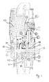
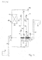
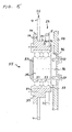
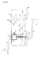
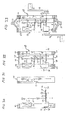
- FIG. 1 shows a schematic diagram of a drive 10 with electric motor 50 and transmission for a small vehicle.
- FIG. 1 schematically shows several embodiments of the drive 10 with different mounting positions for an inner and an outer freewheel.
- An electric motor 50 and a transmission are arranged in a housing 42 from which protrudes a Tretwelle 34 on both sides.
- the transmission is designed as dreikettriges transmission, ie as a transmission with three chains 11, 12 and 13.
- a first reduction stage 21 has a first drive gear 1, which is fixed on a motor shaft 31 of the electric motor 50.
- the first drive gear 1 is mechanically connected via the first chain 11 to a first driven gear 2, which is arranged concentrically around a first intermediate shaft 32.
- the first intermediate shaft 32 is formed as a hollow shaft which is arranged concentrically to the Tretwelle 34.
- the second reduction stage 22 has a second drive gear 3, which is arranged concentrically around the first intermediate shaft 32.
- the second drive gear 3 is mechanically connected via the second chain 12 to a second driven gear 4, which is fixed on a second intermediate shaft 33.
- the third reduction stage 23 has a third drive gear 5 which is fixed on the second intermediate shaft 33 together with the second output gear 4.
- the third drive gear 5 is mechanically connected via the third chain 13 with a third output gear 6 rotatably connected.
- the third driven gear 6 is arranged concentrically around an output shaft 35.
- the output shaft 35 is formed as a hollow shaft, which is mounted concentrically to the Tretwelle 34.
- the output gear 2 of the first reduction stage 21 and the drive gear 1 of the motor shaft 31 are disposed in a first reduction stage plane
- the drive gear 3 and the output gear 4 of the second reduction stage 22 are disposed in a plane of the second reduction stage 22
- the drive gear 5 and the driven gear 6 of the third reduction stage 23 are arranged in a plane of the third reduction stage.
- Tretwelle 34 is mounted in two rotary unions 71 and 72 of two opposing housing covers 43 and 44 of the housing 42.
- Fig. 1 possible installation positions for an internal freewheel are marked with P23 and P67.
- the inner freewheel transmits in the locked state, a drive torque from the Tretwelle 34 on a hollow shaft which is arranged concentrically with the Tretwelle 34.
- an inner ring of the inner freewheel on the Tretwelle 34 is formed in each case and an outer ring of the inner freewheel is formed on the hollow shaft.
- the outer ring of the inner freewheel is formed on the first intermediate shaft 32, around which the gears 2 and 3 are concentrically arranged.
- the outer ring of the inner freewheel is formed on the output shaft 35 on which the gears 6 and 7 are arranged.
- Possible installation positions for an external freewheel are marked with P1 - P6.
- the outer freewheel transmits in the locked state, a drive torque of the motor 43 on a hollow shaft which is arranged concentrically to Tretwelle 34.
- An installation of a freewheel at the positions P1 and P2, P3, P4, P5, P6 means that the gear 1 and the gear 1, 2, 3, 4, 5, 6 is mounted on the outer freewheel.
- An inner ring of the outer freewheel is formed on the hollow shaft.
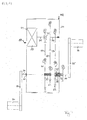
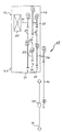
- FIG. 2 shows an embodiment of a drive 10 according to FIG. 1 ,
- the second intermediate shaft 35 is designed as a freewheeling shaft 39.
- the freewheel shaft 39 is passed through the first intermediate shaft 32.
- a double hollow shaft or a double shaft is formed, wherein the first intermediate shaft 32 forms an outer hollow shaft of the double hollow shaft and the freewheeling shaft 39 forms an inner hollow shaft of the double hollow shaft.
- the freewheel shaft 39 carries on a side directed toward the first housing cover 43 an inner freewheel 40 which is clampingly engageable with the Tretwelle 34.
- This inner freewheel 40 is indicated schematically by a symbol.
- the inner freewheel 40 is disposed on the side of the motor 43 and outside the planes of the three reduction stages 21, 22, 23.
- This arrangement of the inner freewheel 40 has the advantage that the motor-side space, which is outside the planes of the reduction stages 21, 22, 23, is utilized for the inner freewheel 40.
- the double shaft carried by the trough 34 can be fabricated as a pre-assembled assembly of the triple-gearing and tested as an assembly prior to installation in the drive.
- the first intermediate shaft 32 carries an outer freewheel 41 which is clampingly engageable with a hollow shaft 69, on which the drive gear 2 is arranged.
- This outer freewheel 41 is also indicated schematically by a symbol.
- the freewheel shaft 39 is constructed in several stages and has a first step for the seat 65 with a shoulder edge, so that a hub 19 of the driven gear 6 is axially secured.
- the outer diameter of the freewheeling shaft 39 increases from stage to stage. This is in Fig. 3 particularly recognizable.
- the drive gears 1, 3 and 5 have in the gear shown the same number 21 of teeth.
- the output gears 2 and 4 have an equal number 75 of teeth.
- the first reduction stage 21 increases the relatively low engine torque by a factor of 75/21 to a higher torque of the first intermediate shaft 32 of the double hollow shaft, and reduces the speed of the first intermediate shaft 32 by the same factor.
- the second reduction stage 22 since the reduction ratio of the first reduction stage 21 is equal to the reduction ratio of the second reduction stage 22, the second reduction stage 22 further increases the torque by the same factor and further reduces the rotation speed of the second intermediate shaft 33 by the same factor.
- the torque with the third reduction stage 23 is increased again by a factor of 57/21, so that an output torque is available via the freewheel shaft 39 of the double hollow shaft on the trough shaft 34.
- the output torque is higher by a factor of about 35 than the engine torque and is sufficient to transmit an adapted starting torque to a small vehicle impeller.
- the output speed of the Tretwelle 34 is reduced by the total reduction of the transmission of about 35 compared to the engine speed.
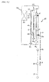
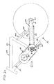
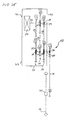
- Fig. 3 shows an exploded view showing components that are arranged on the Tretwelle 34 and the Tretwelle 34 around.
- Fig.2 shows, from the drive side to the output side forth, a first crank lug 77, a motor-side Tretwellenlager 78, a second crank projection 79, the inner freewheel 40, an outer ring 80 of the inner freewheel 40 with attached freewheel shaft 39, a retaining ring 81, a drive-side bearing 82 of the drive gear 3, a output side bearing 83 of the driven gear 3, a first intermediate shaft 32 with attached third output gear 3, the outer freewheel 41, a hollow shaft 69 with attached output gear 2, a bearing 84 of the output gear 2, a retaining ring 85, a hollow shaft 86 of the output gear 6, and a bearing 87 of the driven gear 6 and a retaining ring 88.
- the hollow shaft 86 of the output gear is mounted on the freewheel shaft 39.
- the hollow shaft 86 is a part of in Fig. 2 shown hollow shaft 39. This component is in Fig. 2 not shown as a separate component for reasons of clarity.
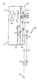
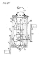
- FIG. 4 shows a sectional view of the motor gear unit of Fig. 2 ,
- a ball bearing 90 for supporting the output gear 6 of the third gear ratio in the housing and two oppositely oriented angular contact bearings 91, 92 for supporting the output gear 4 of the second reduction stage and the drive gear 5 of the third reduction stage.
- FIGS. 5 to 11 show further embodiments of a drive 10 according to Fig. 1 , Also in the embodiments according to the FIGS. 5 to 11 it is possible to install the inner freewheel 40 motor side.
- the output shaft 35 passed through the first intermediate shaft 32, so that the output shaft forms an inner hollow shaft 39 of a double hollow shaft.
- FIG. 2 shows an installation of the inner freewheel 40 at position P67 and an installation of the outer freewheel under the output gear 2. The in FIG. 2 Installation is advantageous in a multi-channel transmission for reasons of space, since a part of the outer freewheel 41 can be accommodated in the space which is located on the motor side of the levels of the reduction stages.
- a compact space-saving drive is created by the double hollow shaft structure.
- the Tretwelle is used as a bottom bracket, the inner freewheel ensures that the pedals of cranks can be kept in rest position, although the electric motor drives the output gear 6.
- the arrangement of the freewheel opposite to the built-in drive electric motor of the existing space is used there and created a compact drive unit.
- This drive is not only suitable for bicycle drives but for all small vehicles with pedal drive such as pedal boats, scooters, etc., which are provided with an additional drive with electric motor.
- the inner output shaft 35 projects out of the housing on one side and the output gear 7 is fixed on this protruding end of the freewheel shaft.
- the output gear 7 may also be arranged on the protruding end of the Tretwelle 34.
- the protruding on both sides of the housing shaft additionally have a differential gear. This allows improved drive and cornering for small vehicles with two ground wheels on two half-waves.
- a driver may set the degree of engine assistance using a double freewheel according to the application, for example, by sensing how long the pedaling frequency is higher than the engine speed and how long the engine speed is greater than the pedaling frequency.
- the engine speed adapts to the pedaling frequency according to the application: For example, if the pedaling frequency is higher than the engine speed, the engine speed will automatically increase for a given engine power since the engine now runs virtually unloaded due to the outer freewheel. Among other things, by the inertia of the drive train, the switching back and forth between engine and muscle power runs largely smoothly.
- the electric drive can be equipped with a manual control.
- a manual control Particularly easy to implement is a rotary handle, by which the supplied electrical power is controlled. Unlike for example in a speed or force control, this requires no sensor, which is attached to moving parts, but only a sensor in the circuit of the battery.
- An electric bicycle with a double freewheel does not require a separate motion or force sensor, but can also be equipped for a more accurate control of the motor with a control circuit in which such a sensor is provided.
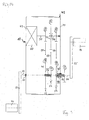
- FIG. 12 shows a schematic diagram of another embodiment of a drive 10 with electric motor 50 and transmission, applied here to a small vehicle. This provides an improved electric motor drive and method of operating the drive.
- the electric motor 50 and the transmission are arranged in a housing 42 from which an output shaft 34 protrudes on one side.
- the transmission is a three-gear transmission, i. designed as a transmission with three chains 11, 12 and 13.
- a first reduction stage 21 has a first drive gear 1, which is fixed on a motor shaft 31 of the electric motor 50.
- the first drive gear 1 is mechanically connected via a first chain 11 to a first output gear 2 rotatably, which is arranged on a first intermediate shaft 32.
- a second reduction stage 22 has a second drive gear 3 fixed on the first intermediate shaft 32 together with the first driven gear 2.
- the second drive gear 3 is mechanically connected via a second chain 12 to a second output gear 4 rotatably connected. That is fixed on a second intermediate shaft 33.
- a third reduction stage 23 has a third drive gear 5, which is fixed on the second intermediate shaft 33 together with the second driven gear 4.
- the third drive gear 5 is mechanically connected via a third chain 13 to a third driven gear 6, wherein the third driven gear 6 is fixed on the output shaft 34 of the drive 10.
- the motor shaft 31 and the second intermediate shaft 33 are provided in alignment with each other.
- the output shaft 34 and the first intermediate shaft 32 are also aligned with each other.
- the drive gears 1, 3 and 5 have in the illustrated gear on the same number of teeth.
- the output gears 2 and 4 have the same number of teeth.
- an output gear 7 is arranged to drive the impeller 26 outside the housing 42.
- the output gear 7 is coupled via the chain drive 14 and via a drive gear 8 with a hub gear 41 of the impeller 26 of a small vehicle.
- the reduction ratio of the first and the second reduction stage are the same and are realized with the same size gears, and if the motor shaft and the first intermediate shaft and also the output shaft and the second intermediate shaft are aligned, then with the same pitch and chain pitch, for example mm chains of the same length used and the housing structure can be simplified inexpensively.
- the transmission ratio U is increased by adjusting the number of teeth.
- a range of 8: 1 to 60: 1 is provided.
- the number of teeth per sprocket of the drive gears 1, 3 and 5 is not less than 19, preferably between 19 to 25, which favors a low noise.
- the number of teeth per sprocket of the driven gears 2, 4 and 6 of the reduction stages 21, 22 and 23 can be between 45 and 85, without the wrap angle of the chains on the associated driven gears is too low.
- the impeller may have a derailleur.
- a derailleur For a higher variation of the starting and acceleration moments is possible, especially since not only in the hub area additional gears are possible, but also a plurality of sprockets can be fixed on the output shaft, and the chain drive 14 can be made switchable between them.
- the output shaft 34 may be coupled directly to a hub of an impeller of a small vehicle, which is particularly suitable for wheelchairs, motorized three and four wheels.
- the output shaft 34 may be coupled to the hub 41 via a belt drive, the output shaft 34 having a first pulley and the hub 41 of the impeller 26 via a second pulley by means of a drive belt or a V-belt or a toothed belt is driven.
- V-belt drives compared to chain drives allow reduced noise, which is advantageous for small vehicles in medical areas.
- the output shaft 34 with a friction wheel, wherein the friction wheel with a wheel tire or with a wheel rim is coupled.
- the output shaft 34 may carry a gear pinion and the rim of the impeller having an internal gear, wherein the teeth of the pinion can be brought into engagement with the inner ring gear of the rim.
- this construction can also be used for recuperation of braking energy. Since braking accelerations can generate charging current in downhill and braking operations of the impeller in the electric motor.
- a protruding on both sides of the housing shaft may be connected to pedals having cranks, a freewheel is provided for the cranks.
- This variant is particularly suitable for bicycle drives and small vehicles with pedal drive such as pedal boats, scooters u.a., Which are provided with an additional drive with electric motor.
- the electric motor can be equipped with a reversal of rotation, wherein in the case of a bilateral emerging from the housing shaft, a reversible freewheel can be provided. This can improve the maneuverability of wheelchairs and other three- or four-wheeled small vehicles.
- a protruding on both sides of the housing shaft may additionally have a differential gear. This allows improved drive and cornering for small vehicles with two ground wheels on two half-waves.
- List of reference numerals for FIG. 12 1 first drive gear of the first reduction stage 2 first output gear of the first reduction stage 3 second drive gear of the second reduction stage 13 third chain of the first reduction stage 4 second output gear of the second reduction stage 14 chain drive 21 first reduction stage 5 third drive gear of the third reduction stage 22 second reduction stage 23 third reduction stage 6 third output gear of the third reduction stage 26 Wheel 31 motor shaft 7 Drive gear of the drive 32 first intermediate shaft 8th Drive gear of the impeller 33 second intermediate shaft 10 drive 34 output shaft 11 first chain of the first reduction stage 41 Hub of the wheel 42 casing 12 second chain of the first reduction stage 50 electric motor
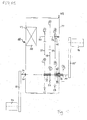
- FIG. 13 shows a schematic diagram of another drive 10 with electric motor 50 and transmission for a small vehicle according to an embodiment of the application.
- the electric motor and the transmission are arranged in a housing 42, from which an output shaft 34 protrudes on one side.
- the transmission is designed as dreikettriges transmission, ie as a transmission with three chains 11, 12 and 13.
- the three chains have different pitches according to DIN 8187, wherein increases with increasing pitch of the diameter of the transverse rollers on stronger cross bolt of the chain links and thus the chain thickness.
- the first reduction stage 21 has a first drive gear 1, which is fixed on a motor shaft 31 of the electric motor 50.
- the first drive gear 1 is mechanically connected via the first chain 11 to a first driven gear 2, which is arranged on a first intermediate shaft 32.
- the second reduction stage 22 has a second drive gear 3 fixed on the first intermediate shaft 32 together with the first driven gear 2.
- the second drive gear 3 is mechanically connected via the second chain 12 to a second driven gear 4 rotatably connected. That is fixed on a second intermediate shaft 33.
- the third reduction stage 23 has a third drive gear 5 which is fixed on the second intermediate shaft 33 together with the second output gear 4.
- the third drive gear 5 is mechanically connected via the third chain 13 to a third driven gear 6, wherein the third driven gear 6 is fixed on the output shaft 34 of the drive 10.
- the motor shaft 31 and the second intermediate shaft 33 are provided in alignment with each other.
- the output shaft 34 and the first intermediate shaft 32 are also aligned with each other.
- the drive gears 1, 3 and 5 have in the illustrated gear on the same number of teeth.
- the output gears 2 and 4 have the same number of teeth.
- an output gear 7 is arranged to drive the impeller 26 outside the housing 42.
- the output gear 7 is coupled via the chain drive 14 by means of a conventional bicycle chain and via a drive gear 8 with a hub gear 41 of the impeller 26 of a small vehicle.
- the pitch and thickness of the first chain 11 is governed by the greater strength and pitch of the second chain 12, although the first chain has a lower torque to transmit.
- the reduction ratios of the first and second reduction stages are the same as in this transmission and are realized with gears of equal size, and when the motor shaft and the first intermediate shaft and also the output shaft and the second intermediate shaft are aligned. Then with the same pitch and chain link pitch and thus the same chain thickness of the same length chains can be used and the housing structure can be simplified cost.
- the output shaft 34 may be coupled to the hub 41 via a belt drive, wherein the output shaft 34 has a first pulley and the hub 41 of the impeller 26 via a second Pulley is driven by means of a drive belt or a V-belt or a toothed belt.
- This alternative has the advantage that V-belt drives compared to chain drives allow reduced noise, which is advantageous for small vehicles in medical areas.
- the output shaft 34 with a friction wheel, wherein the friction wheel with a wheel tire or with a wheel rim is coupled.
- the manufacturing and assembly costs can be reduced, especially since the drive can be grown virtually without costly changes a small vehicle.
- the output shaft 34 may carry a gear pinion and the rim of the impeller having an internal gear, wherein the teeth of the pinion can be brought into engagement with the inner ring gear of the rim.
- this construction can also be used for recuperation of braking energy. Since braking accelerations can generate charging current in downhill and braking operations of the impeller in the electric motor.
- the electric motor may be equipped with a reversal of rotation, wherein in the case of a bilateral emerging from the housing shaft, a reversible freewheel can be provided. This can improve the maneuverability of wheelchairs and other three- or four-wheeled small vehicles.
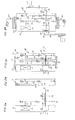
- FIG. 14 shows a schematic diagram of a drive 10 with electric motor 50 and transmission for a small vehicle according to an embodiment of the application.
- the electric motor 50 and the transmission are arranged in a housing 42 from which an output shaft 34 protrudes on one side.
- the transmission is designed as dreikettriges transmission, ie as a transmission with three chains 11, 12 and 13.
- a first reduction stage 21 has a first drive gear 1, which is fixed on a motor shaft 31 of the electric motor 50.
- the first drive gear 1 is mechanically connected via the first chain 11 to a first driven gear 2, which is arranged on a first intermediate shaft 32.
- the second reduction stage 22 has a second drive gear 3 fixed on the first intermediate shaft 32 together with the first driven gear 2.
- the second drive gear 3 is mechanically connected via the second chain 12 rotatably connected to a second output gear 4 which is fixed on a second intermediate shaft 33.
- the third reduction stage 23 has a third drive gear 5 which is fixed on the second intermediate shaft 33 together with the second output gear 4.
- the third drive gear 5 is mechanically via the third chain 13 with a third Output gear 6 rotatably connected, wherein the third output gear 6 is fixed on the output shaft 34 of the drive 10.
- the motor shaft 31 and the second intermediate shaft 33 are provided in alignment with each other.
- the output shaft 34 and the first intermediate shaft 32 are also aligned with each other.
- the second intermediate shaft 33 carries the gears 4 and 5 and is designed as a hollow shaft and rotatably supported on a stationary shaft journal 35 and independently of the motor shaft 31.
- the shaft journal 35 has a shaft journal flange 36, which is fixed on an inner side 47 of a housing cover 44 of the housing 42.
- FIG. 15 shows a schematic representation of a bearing 33 of the second intermediate shaft 33 in detail.
- the inner side 47 of the housing cover 44 has a recess 46, which is adapted to slide an outer contour of the Wollenzapfenflansches 36 slidably.
- the shaft journal flange 36 is fixed to the housing cover 44 with fixing screws 37.
- the Wollenzapfenflansch 36 bag threaded holes.
- the outer rings of the bearings 51 and 52 carry the intermediate shaft 33 designed as a hollow shaft.
- the outer rings of the roller bearings 51 and 53 are secured by a projection 38 on the inner edge of the intermediate shaft 33 and by a locking disc 54 against axial displacement.
- the outer contour of the intermediate shaft 33 has 3 stages 56, 57 and 58.
- the steps 56 and 57 are adapted to different hub shapes of the gears 5 and 4, respectively.
- the step 58 projects beyond the step 57 and forms a shoulder flank 59 for the gear 4, while a step between the steps 56 and 57 forms a shoulder flank 60 for the gear 5.
- This intermediate shaft bearing 55 is related to the assembly of dreikettrigen transmission.
- the gears 4 and 5 are fixed on the steps 57 and 56 of the intermediate shaft 33 with their hubs, wherein the approach edges 59 and 60 contribute to the fixation.
- the rolling bearings 51 and 52 in the hollow shaft is pressed up to the projection 38 and axially secured by the locking disc 54.
- the shaft journal 35 is then pushed.
- the inner rings are secured by attaching the snap ring 53 in a radial groove of the shaft journal 35 against axial displacement.
- a second intermediate shaft 33 designed as a hollow shaft can also be mounted on the motor shaft 31. This makes it possible to ensure an exact alignment of the intermediate shaft with the motor shaft, regardless of manufacturing and assembly tolerances of a housing cover.
- an inner snap ring can be inserted into the hollow shaft for axially securing the outer rings of the rolling bearings 51 and 52, when the hollow shaft is extended axially.
- the use of a snap ring requires less installation time than fixing the locking disc.
- a central self-locking fixing nut can also be provided for fixing the shaft journal flange 36, if a corresponding threaded pin of the shaft journal flange protrudes through the housing cover to the outside. This allows a simplified mounting of the shaft journal on the housing cover
- FIG. 12 and 13 are also applicable to the present embodiment. Additional reference numerals in FIGS. 14 and 15 35 shaft journal 53 snap ring 36 Wellenzapfenflansch 54 axial locking disc 37 fixing screw 55 storage 38 approach 56 Stage on the intermediate shaft 42 casing 57 Stage on the intermediate shaft 44 housing cover 58 Stage on the intermediate shaft 46 Recess in a housing cover 59 Approach edge between levels 58 and 57 47 Inside of a housing cover 60 Approach edge between levels 57 and 56 50 electric motor 51 roller bearing 52 roller bearing
- the shaft journal 35 is individually relevant and identifiable as a separate object.
- the shaft journal 35 has a shaft journal flange 36, which is fixed on an inner side 47 of a housing cover 44 of the housing 42. Further possible features of the shaft journal 35 which can be arranged in the three-coupled gearbox are disclosed in the above description.
- a further embodiment may be provided as an alternative or in addition to Wollenzapfenflansch a design in which the shaft journal 35 at its free end FIG. 15 is extended in the direction of the motor shaft 31 out.
- the shaft journal 35 occurs there via a bearing with the motor shaft 31 in contact, but is rotatable relative to this by the bearing. This improves the durability of the Transmission, when the shaft 35 is mounted on both sides for the gears 4 and 5.
- the prerequisite is that the motor shaft 31 is stored stable in itself.
- a fixed-lot bearing assembly for the connection of the motor shaft 31 and shaft journals 35 can be selected, wherein the fixed bearing can also be provided on the motor shaft 31. This then favors a mounting of the transmission.
- FIG. 16 shows a schematic diagram of another drive 10 with electric motor 50 and transmission for a small vehicle according to an embodiment of the application.
- the electric motor 50 and the transmission are arranged in a housing 42 from which an output shaft 34 protrudes on one side.
- the transmission is designed as dreikettriges transmission, ie as a transmission with three chains 11, 12 and 13.
- a first reduction stage 21 has a first drive gear 1, which is fixed on a motor shaft 31 of the electric motor 50.
- the first drive gear 1 is mechanically connected via a first chain 11 to a first driven gear 2, which is arranged on a first intermediate shaft 32.
- a second reduction stage 22 has a second drive gear 3 fixed on the first intermediate shaft 32 together with the first driven gear 2.
- the second drive gear 3 is mechanically connected via a second chain 12 to a second driven gear 4, which is fixed on a second intermediate shaft 33.
- a third reduction stage 23 has a third drive gear 5, which is fixed on the second intermediate shaft 33 together with the second driven gear 4.
- the third drive gear 5 is mechanically connected via a third chain 13 to a third driven gear 6, wherein the third driven gear 6 is fixed on the output shaft 34 of the drive 10.
- the motor shaft 31 and the second intermediate shaft 33 are provided in alignment with each other.
- the output shaft 34 and the first intermediate shaft 32 are also aligned with each other.
- the drive gears 1, 3 and 5 have in the gear shown the same number 21 of teeth.
- the output gears 2 and 4 have an equal number 75 of teeth.
- the relatively low engine torque is increased by a factor of 75/21 to a higher torque of the first intermediate shaft 32, and the speed of the first intermediate shaft 32 is reduced by the same factor.
- the second reduction stage 22 since the reduction ratio of the first reduction stage 21 is equal to the reduction ratio of the second reduction stage 22, the second reduction stage 22 further increases the torque by the same factor and further reduces the rotation speed of the second intermediate shaft 33 by the same factor.
- the torque with the third reduction stage 23 is again increased by a factor of 57/21, so that an output torque is available that is higher by a factor of about 35 than the engine torque and sufficient to a matched starting torque on an impeller 26 of Small vehicle using a chain drive 14 to transfer. In this case, the output speed of the output shaft 34 is reduced by the total reduction of the transmission of about 35 relative to the engine speed.
- the shafts 32 to 34 with the hubs 15 to 19 of the gears 2 to 6 non-positively, material or positively connected.
- the gears 2 to 6 sit with their hubs 15 to 19 on stepped hollow shafts, wherein the steps are adapted with their outer contour to the shapes of the hub openings of the gears 2 to 6.
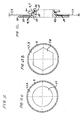
- FIG. 17 shows schematic representations of different hub shapes of gears of the transmission.
- Figure 17A shows a schematic representation of the Drive gears 1, 2 or 3 as in FIG. 1 shown with a circular hub opening 29 and a sprocket 9 with the 21 teeth.
- the drive gears with a circular hub opening 29 are positively or materially fixed on a stage of a shaft to transmit the torques of the shaft to the ring gear 9.
- Figure 17B shows a same drive gear 1, 3 or 5 as in FIG. 1 shown with a hexagonal hub opening 28, which has an equilateral hexagon.
- the equilateral hexagon is positively fixed on a hexagonal step of a shaft and transmits the torques of the shaft to the sprocket 9.
- Figure 17C shows a schematic representation of a stepped shaft, as provided for the intermediate shafts 32 and 33.
- the step 56 is adapted in shape and size to the hub openings 28 and 29 of the drive gears 3 and 5 respectively.
- the step 57 is adapted in shape and size to the hub openings of the driven gears 2 and 4.
- a shoulder flank 60 is provided with which the drive gear 3 and 5 is fixed axially.
- a third step 58 is larger than the step 57 and forms a step flank 59 towards the step 57 so that the driven gear 2 or 4 is fixed axially to the flank 59.
- Gear hubs with circular hub opening have the advantage that their seat can be inexpensively manufactured on a shaft, since only one step is to be rotated in a shaft material for the seat of the gear hub on the shaft.
- the gear hubs with hexagonal hub opening shown here have the advantage that their seat is positively connected to a shaft and the torques of a shaft on the sprockets can be positively transferred via this positive fit.
- Polygonal hub openings have the advantage that gears can be glued to the hub, for example, with polymer adhesive, which is very cost-effective. Soldering or welding is also conceivable.
- the polygonal hub opening are dowel pins, rivets or screw, which are arranged in the gear blade and which are fixed in the stepped shaft in the region of the shoulder flank provided. This also gears with circular hub opening can be positively fix.
- the particular hub shapes are individually relevant and identifiable as a separate item.
- the article can be used especially in dreikettrigen transmissions.
- FIG. 18 shows schematic representations of different hub shapes of gears of the transmission.
- FIG. 2A shows a schematic representation of the output gears 1, 2 or 3 as in FIG. 1 shown with a circular hub opening 29 and a sprocket 9 with the 21 teeth.
- the drive gears with a circular hub opening 29 are positively or materially fixed on a stage of a shaft to transmit the torques of the shaft to the ring gear 9.
- FIG. 2B shows a same drive gear 1, 3 or 5 as in FIG. 1 shown with a hexagonal hub opening 28, which has an equilateral hexagon.
- the equilateral hexagon is positively fixed on a hexagonal step of a shaft and transmits the torques of the shaft by means of positive engagement with the ring gear 9.
- Figure 2C shows a schematic representation of a stepped shaft, as provided for the intermediate shafts 32 and 33, respectively.
- the step 56 is adapted in shape and size to the hub openings 28 and 29 of the drive gears 3 and 5, respectively.
- the step 57 is adapted in shape and size to the hub openings of the driven gears 2 and 4, respectively.
- a shoulder flank 60 is provided with which the drive gear 3 and 5 is fixed axially.
- a third step 58 is larger than the step 57 and forms a step flank 59 towards the step 57 so that the driven gear 2 or 4 is fixed axially to the flank 59.
- the equally sized driven gears 2 and 4 which are provided with a circular hub opening 29, fixed with their gear blades on one side with an adhesive layer 25 on the shoulder flank 59.
- Another adhesive layer 25 is between the hub 15 and 16, respectively, in FIG FIG. 1 shown gears 2 and 4 and the lateral surface of the second stage 57 of the intermediate shaft 32 and 33, respectively.
- an adhesive is first applied to the shoulder 59 of the intermediate shaft 32 and 33, respectively.
- the outer surface of the second stage 57 is coated with adhesive and the driven gear is pressed onto the second shaft stage 57 and the adhesive cured to an adhesive layer 25.
- Providing an adhesive layer between the gear blades and the stepped flanks of a stepped shaft provides a cost effective and reliable connection between the gear hub and shaft so that torques of the shaft can be securely transmitted through the gear hub to the sprocket of a gear.
- the gears are aligned by the heel flanks of the stepped shaft and fixed axially, so that a reliable chain guide is ensured by the sprocket.
- adhesive layer 25 may be provided a soft solder or brazing layer. Solder layers are more stable than adhesive layers at elevated operating temperatures.
- spot welds may be provided between the gear blades and the land flanks or spot welds at the transition from a shaft stage to the gear blades. Spot welds and spot welds, for example, by laser welding are more stable at elevated operating temperature than adhesive layers and reduce manufacturing costs.
- gears with circular hub openings and gears with hexagonal hub opening with an adhesive layer can be fixed on one side between their gear blades and the shoulder edge.
- the adhesive layer or, alternatively, a soft solder or braze layer or spot welds, assures the axial alignment and fixation of the gears.
- the particular hub shapes and the bonding of the gears on the hubs are individually relevant and identifiable as a separate item.
- the article can be used especially in dreikettrigen transmissions.
- FIG. 19 shows a schematic diagram of a drive 10 with electric motor 50 and transmission for a small vehicle according to an embodiment of the application.
- the electric motor 50 and the transmission are arranged in a housing 42 from which an output shaft 34 rotatably protrudes on both sides in rotary unions 71 and 72.
- the transmission is designed as dreikettriges transmission, ie as a transmission with three chains 11, 12 and 13 and has a modular structure with four modules.
- a motor shaft assembly 61 comprises as a first assembly the electric motor 50 with a motor shaft 31 on which a first drive gear 1 is arranged.
- the electric motor 50 has an electric motor housing 66 with an electrical connection region 67 which is attached to a first housing cover 43.
- the motor shaft 31 protrudes opposite to the connection portion 67 out of the electric motor housing 66 and carries the first drive gear.
- An output shaft assembly 62 includes as a second assembly the both sides of the housing 42 protruding output shaft 34, a freewheel shaft 39 and a first intermediate shaft 32 of the transmission.
- the freewheel shaft 39 is rotatably supported on the output shaft 34 and the first intermediate shaft 32 is rotatably supported on the freewheel shaft 39.
- the output shaft 34 carries within the housing 42 a measuring wheel 49 for detecting output speeds.
- the freewheel shaft 39 carries on a side facing the first housing cover 43 a freewheel 40, the direction of rotation dependent on the output shaft 34 is clampingly engageable.
- the freewheel shaft 39 has a seat 65 for an output gear assembly 64 on a side directed toward a second housing cover 44.
- the intermediate shaft 32 carries a first output gear 2 of a first reduction stage 21 and a second drive gear 3 of a second reduction stage 22 of the dreikettrigen transmission.
- the first output gear 2 on the first intermediate shaft 32 is aligned opposite to the first drive gear 1 of the motor shaft assembly 61 such that the first chain 11 of the first reduction stage 21 engages with sprockets of the gears 1 and 2.
- the second drive gear 3 on the first intermediate shaft 32 is aligned opposite to a second driven gear 4 such that a second chain 12 of the second reduction stage 22 is meshed with sprockets of the gears 3 and 4.
- a shaft journal assembly 63 has as a third assembly a shaft journal 35 and a second intermediate shaft 33 which is rotatably mounted on the shaft journal 35.
- the shaft journal 35 has toward the second housing cover 44 toward a shaft journal flange 36, with which the shaft journal 35 on the second housing cover 44th is fixed.
- the second output gear 4 and a third drive gear 5 of a third reduction stage 23 is fixed.
- An output gear assembly 64 has an output gear 6 and a hub 19 of the output gear 6.
- the hub 19 is fixed on the seat 65 of the freewheel shaft 39.
- the driven gear 6 is aligned such that a third chain 13 of the third reduction stage 23 meshes with sprockets of the gears 5 and 6.
- first the first housing cover 43 for receiving the motor shaft assembly 61 and the output shaft assembly 62 is manufactured.
- the motor shaft assembly 61 having the motor shaft 31 and the first drive gear 1 fixed on the motor shaft 31 is manufactured as a stationary first assembly.
- the output shaft assembly 62 is produced with the output shaft 34, the freewheel shaft 39 and the first intermediate shaft 32 of the transmission as a separate second assembly.
- the motor shaft assembly 61 is mounted on the first housing cover 43 with access to the electrical connection portion 67, and the outer shaft 34 of the output shaft assembly 62 is inserted into the first rotary leadthrough 71 of the first housing cover 43.
- the assemblies 61 and 62 are arranged on the first housing cover 43, that the first drive gear 1 of the motor shaft assembly 61 is aligned with the first output gear 2 of the output shaft assembly 62 and that the first chain 11 of the first reduction stage 21 with sprockets of the Gears 1 and 2 is engaged.
- the shaft journal assembly 63 is provided with the shaft journal 35 and the second intermediate shaft 33 of the transmission as a separate third assembly.
- the shaft journal assembly 63 is aligned with respect to the output shaft assembly 62 so that the second drive gear 3 is disposed on the first intermediate shaft 32 opposite to the second output gear 4 of the second intermediate shaft is, and that a second chain 12 of the second reduction stage 22 with gears of the gears 3 and 4 is engaged.
- the output gear assembly 64 is then provided with the hub 19 and the output gear 6 as a separate fourth assembly. Then, the output gear assembly 64 is fixed and aligned on the seat 65 of the free wheel shaft 39 such that the third chain 13 of the third reduction stage 23 is engaged with sprockets of the gears 5 and 6.
- the motor shaft assembly 61 in a first step can also be mounted on the first housing cover 43 with access to the electrical connection region 67, with the gearwheel 1 still omitted and the output shaft assembly added.
- a unit is then fabricated from the output shaft assembly 62, from the journal assembly 63 and from the output gear assembly 64, the individual shafts being interconnected by the chains 11, 12, and 13. This unit of output shaft assembly 62, shaft journal assembly 63 and output gear assembly 64 is then inserted into the housing cover with the gear 1 mounted on the motor shaft 31.
- a second housing cover 44 is ready and is placed on spacers 48 while inserting the output shaft 34 into the rotary union 72.
- the shaft journal 35 of the shaft journal assembly 63 is also mounted in alignment with the motor shaft 31. Thereafter, the shaft journal flange is attached to the second housing cover.
- the housing middle part 45 protects the drive 10 from contamination and is media-tight with the housing covers 43 and 44 connected.
- an output gear 7 is placed in the direction of arrow B to complete.
- the drive gears 1, 3 and 5 have in the gear shown the same number 21 of teeth.
- the output gears 2 and 4 have an equal number 75 of teeth.
- the modular design of the drive has the advantage that the four modules can be manufactured and stored individually.
- the assembly of the drive can be carried out inexpensively in a mass production.
- the assembly of modules to drives can be made cost-effective with production machines. Because each assembly can be quality assured, the cost of manufacturing defects is reduced.
- the motor shaft is not charged additionally. Furthermore, the assembly of the dreikettrigen transmission is facilitated by pre-assembly of the shaft journal assembly. If first the first chain of the first reduction stage is applied between the first and second assembly, then the chain of the second reduction stage can then be connected to the preassembled third assembly. After attaching the fourth assembly finally the third chain between the third and fourth assembly can be mounted. Only thereafter, the second housing cover is applied while fixing the shaft journal in the interior and by performing an output shaft end to the outside.
- the housing covers may belong to the supporting structure of a frame of a small vehicle and the distance between the two housing covers is provided by the supporting structure. This makes it possible to reduce the space requirement of the drive and to integrate the drive in the supporting structure of the small vehicle.
- a two-part housing middle part can also assume this function, with a second part of the two-part housing middle part covering an inspection and assembly auxiliary opening. This has the advantage that a drive housing is available, which can be attached to any small vehicles.
- a second intermediate shaft 33 designed as a hollow shaft can also be mounted on the motor shaft 31 are stored. This makes it possible to ensure an exact alignment of the intermediate shaft 33 with the motor shaft 31 regardless of manufacturing and assembly tolerances of a housing cover.
- FIG. 20 shows a schematic diagram of a drive 10 with electric motor 50 and transmission for a small vehicle according to an embodiment of the application.
- the electric motor 50 and the transmission are arranged in a housing 42, protruding from both sides of an output shaft 34.
- the transmission is designed as dreikettriges transmission, ie as a transmission with three chains 11, 12 and 13.
- a first reduction stage 21 has a first drive gear 1, which is fixed on a motor shaft 31 of the electric motor 50.
- the first drive gear 1 is mechanically connected via the first chain 11 to a first driven gear 2, which is arranged on a first intermediate shaft 32.
- the second reduction stage 22 has a second drive gear 3 fixed on the first intermediate shaft 32 together with the first driven gear 2.
- the second drive gear 3 is mechanically connected via the second chain 12 to a second driven gear 4, which is fixed on a second intermediate shaft 33.
- the third reduction stage 23 has a third drive gear 5 which is fixed on the second intermediate shaft 33 together with the second output gear 4.
- the third drive gear 5 is mechanically connected via the third chain 13 with a third output gear 6 rotatably connected.
- the output shaft 34 projecting from the housing 42 on both sides is mounted in two rotary feedthroughs 71 and 72 by two opposite housing covers 43 and 44.
- the drive shaft 34 carries to a first housing cover 43 toward a measuring wheel 49 for measuring the output speed of the output shaft 34.
- On the Output shaft 34 are two hollow shafts 32 and 39 rotatably supported as a double hollow shaft.
- An inner hollow shaft 68 is formed as a freewheeling shaft 39.
- the freewheeling shaft 39 carries on a side directed toward the first housing cover 43 a freewheel 40, the direction of rotation dependent on the output shaft 34 is clampingly engageable.
- the freewheel shaft 39 has a seat 65 for the third output gear 6 of the third reduction stage 23 on a side directed toward a second housing cover 44.
- the intermediate shaft 32 is rotatably supported as an outer hollow shaft 69 of the double hollow shaft with the output gear 2 and the drive gear 3 of the reduction stages 21 and 22, respectively.
- the output gear 2 is aligned with the drive gear 1 of the motor shaft 31 and the drive gear 3 on the output gear 4 of the second reduction stage 22.
- the freewheel shaft 39 is constructed in several stages and has a first step for the seat 65 with a shoulder edge, so that a hub 19 of the driven gear 6 is axially secured.
- the double hollow shaft carried by the output shaft 34 forms a preassemblable assembly of the three-gear transmission and is subject to quality control prior to installation in the drive.
- the drive gears 1, 3 and 5 have in the gear shown the same number 21 of teeth.
- the output gears 2 and 4 have an equal number 75 of teeth.
- the first reduction stage 21 increases the relatively low engine torque by a factor of 75/21 to a higher torque of the first intermediate shaft 32 of the double hollow shaft, and reduces the speed of the first intermediate shaft 32 by the same factor.
- the second reduction stage 22 since the reduction ratio of the first reduction stage 21 is equal to the reduction ratio of the second reduction stage 22, the second reduction stage 22 further increases the torque by the same factor and further reduces the rotation speed of the second intermediate shaft 33 by the same factor.
- the torque with the third reduction stage 23 is again increased by a factor 57/21, so that an output torque is available via the freewheel shaft 39 of the double hollow shaft on the output shaft 34.
- the output torque is higher by a factor of about 35 than the engine torque and is sufficient to transmit an adapted starting torque to a small vehicle impeller.
- the output speed of the output shaft 34 is reduced by the total reduction of the transmission of about 35 relative to the engine speed.
- FIG. 1 embodiment shown has the advantage that a compact space-saving drive is created by the double hollow shaft structure.
- the output shaft can be used as a bottom bracket, wherein the freewheel ensures that the pedals of cranks can be kept in rest position, although the electric motor drives the output gear 6.
- the arrangement of the freewheel opposite to the built-in drive electric motor of the existing space is used there and created a compact drive unit.
- the measuring wheel 49 for measuring the output speed of the output shaft 34 is in itself relevant and identifiable as a separate object.
- the object can be used especially in dreikettrigen transmissions, because the installation site provided here is particularly space-saving.
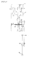
- FIG. 21 shows a schematic diagram of a drive 10 with electric motor 50 and transmission for a small vehicle according to an embodiment of the application.
- the electric motor 50 and the transmission are arranged in a housing 42 from which an output shaft 34 protrudes on one side.
- the transmission is designed as dreikettriges transmission, ie as a transmission with three chains 11, 12 and 13.
- the unilaterally projecting out of the housing 42 output shaft 34 carries to a first housing cover 43 toward a measuring wheel 49 for measuring the output speed of the output shaft 34.
- an inner hollow shaft 68 and an outer hollow shaft 69 are arranged coaxially to each other.
- the inner hollow shaft 68 is with the output shaft 34 rigidly connected.
- the inner hollow shaft 68 has a seat 65 for the third output gear 6 of the third reduction stage 23 on a side directed toward a second housing cover 44.
- the outer hollow shaft 69 is rotatably arranged and forms the first intermediate shaft 32 with the output gear 2 and the drive gear 3 of the reduction stages 21 and 22.
- the driven gear 2 on the drive gear 1 of the motor shaft 31 and the drive gear 3 on the driven gear 4 of the second reduction stage 22 aligned.
- the inner hollow shaft 68 is constructed in multiple stages and has a first step for the seat 65 with a shoulder edge, so that a hub 19 of the driven gear 6 is axially secured.
- the outer diameter of the inner hollow shaft 68 increases from stage to stage.
- the double shaft carried by the output shaft 34 forms a preassembled assembly of the tri-ply transmission and is subject to quality control prior to installation in the drive.
- an output gear 7 is arranged to drive the impeller 26 outside the housing 42.
- the output gear 7 is coupled via the chain drive 14 and via a drive gear 8 with a hub gear 41 of the impeller 26 of a small vehicle.
- FIG. 21 embodiment shown has the advantage that a compact space-saving drive 10 is created by the double hollow shaft structure.
- the output shaft 34 is reinforced by the inner hollow shaft 68, so that both together have a larger area moment of inertia.
- the outer hollow shaft a more robust storage against storage directly on the output shaft can be provided. With this drive concept, a pure electric drive is realized.
- the output gear 6 may be arranged with its hub 19 on the output shaft 34. This has the advantage that the length of the inner hollow shaft can be shortened to the required length for guiding the outer hollow shaft, whereby space and weight is saved.
- FIG. 22 shows a schematic diagram of a drive 10 with electric motor 50 and transmission for a small vehicle according to another embodiment of the application.
- the electric motor 50 and the transmission are arranged in a housing 42, protruding from both sides of an output shaft 34.
- the transmission is designed as dreikettriges transmission, ie as a transmission with three chains 11, 12 and 13.
- a first reduction stage 21 has a first drive gear 1, which is fixed on a motor shaft 31 of the electric motor 50.
- the first drive gear 1 is mechanically connected via the first chain 11 to a first driven gear 2, which is arranged on a first intermediate shaft 32.
- the second reduction stage 22 has a second drive gear 3 fixed on the first intermediate shaft 32 together with the first driven gear 2.
- the second drive gear 3 is mechanically connected via the second chain 12 to a second driven gear 4, which is fixed on a second intermediate shaft 33.
- the third reduction stage 23 has a third drive gear 5 which is fixed on the second intermediate shaft 33 together with the second output gear 4.
- the third drive gear 5 is mechanically connected via the third chain 13 with a third output gear 6 rotatably connected.
- the output shaft 34 projecting from the housing 42 on both sides is mounted in two rotary feedthroughs 71 and 72 by two opposite housing covers 43 and 44.
- the drive shaft 34 carries to a first housing cover 43 toward a measuring wheel 49 for measuring the output speed of the output shaft 34.
- two hollow shafts 32 and 39 are rotatably supported as a double hollow shaft.
- An inner hollow shaft 68 is formed as a freewheeling shaft 39.
- the freewheel shaft 39 carries on a side facing the first housing cover 43 an inner side Freewheel 40 which is clampingly engageable with the output shaft 34.
- the freewheel shaft 39 has a seat 65 for the third output gear 6 of the third reduction stage 23 on a side directed toward a second housing cover 44.
- the clamping direction of the inner freewheel 40 corresponds to a forward rotational direction of the output shaft 34.
- the freewheel 40 is clampingly engaged with the output shaft 34 in the forward direction.
- the inner freewheel 40 disengages.
- the clamping direction of the outer freewheel 41 corresponds to a forward rotational direction of the first intermediate shaft 33.
- the outer freewheel 41 is clampingly engaged with the first intermediate shaft.
- the freewheel shaft 39 rotates faster than the first intermediate shaft 33 in the forward rotational direction
- the outer freewheel 41 disengages.
- pedals 74 having cranks 75 are arranged on the protruding from the housing ends of the output shaft 34 pedals 74 having cranks 75 are arranged. On one side is between a pedal crank 75 and the housing 42, an output gear 7 is arranged, which drives a not shown impeller of a small vehicle via a chain drive, not shown.
- the intermediate shaft 32 is rotatably supported as an outer hollow shaft 69 of the double hollow shaft with the output gear 2 and the drive gear 3 of the reduction stages 21 and 22, respectively.
- the output gear 2 is aligned with the drive gear 1 of the motor shaft 31 and the drive gear 3 on the output gear 4 of the second reduction stage 22.
- the freewheel shaft 39 is constructed in several stages and has a first step for the seat 65 with a shoulder edge, so that a hub 19 of the driven gear 6 is axially secured.
- the double shaft carried by the output shaft 34 forms a preassembled assembly of the tri-ply transmission and is subject to quality control prior to installation in the drive.
- FIG. 22 embodiment shown has the advantage that can be supported by the cranksets by the switchable freewheel both a forward run and a reverse rotation of the electric motor.
- the switchable freewheel drive improves the maneuverability of multi-wheeled small vehicles.
- a compact space-saving drive is created by the double hollow shaft structure.
- the output shaft is used as a bottom bracket, wherein the switched freewheel ensures that the pedals of cranks can be kept in rest position, although the electric motor drives the output gear 6.
- the arrangement of the freewheel opposite to the built-in drive electric motor of the existing space is used there and created a compact drive unit.
- FIG. 23 shows a schematic diagram of a drive 10 with electric motor 50 and transmission for a small vehicle according to an embodiment of the application.
- the protruding on both sides of the housing 42 ends 76 and 76 'of the output shaft 34 each carry an output gear 7 and 7'.
- the output shaft 34 is in two rotary unions 71 and 72 of two opposing housing covers 43 and 44 stored.
- two hollow shafts 68 and 69 are rotatably supported as a double hollow shaft, as known from the preceding embodiments.
- An inner hollow shaft 68 carries on a side facing the first housing cover 43 a differential gear 80.
- the differential gear 80 allows different speeds of the two protruding from the housing 42 ends 76 and 76 'of the output shaft 34.
- the inner hollow shaft 68 has a second to a second Housing cover 44 directed towards a seat 65 for a hub 19 of the third output gear 6 of the third reduction stage 23.
- the differential gear 80 has three meshing bevel gears 77, 78 and 78 'on each other.
- a drive bevel gear 77 is connected to the inner hollow shaft 68 via a fork 79, in which the transverse to the output shaft 34 arranged axis 79 of the drive bevel gear 77 is mounted coupled.
- the intermediate shaft 32 is rotatably supported as an outer hollow shaft 69 of the double hollow shaft with the output gear 2 and the drive gear 3 of the reduction stages 21 and 22, respectively.
- the output gear 2 is aligned with the drive gear 1 of the motor shaft 31 and the drive gear 3 on the output gear 4 of the second reduction stage 22.
- the inner hollow shaft 68 is constructed in multiple stages and has a first step for the seat 65 with a shoulder edge, so that a hub 19 of the driven gear 6 is axially secured.
- the outer diameter of the inner hollow shaft 68 increases from stage to stage.
- the double shaft carried by the output shaft 34 forms a preassembled assembly of the tri-ply transmission and is subject to quality control prior to installation in the drive.
- FIG. 23 embodiment shown has the advantage that by the differential gear of the inner hollow shaft of the drive with the protruding on both sides of the housing ends of the output shaft improved cornering for small vehicles with two mutually aligned wheels is possible, which improves the maneuverability of the small vehicle.
- the arrangement of the freewheel opposite to the built-in drive electric motor of the existing space is used there and created a compact drive unit.
- the ends 76 and 76' of the output shaft 34 may be directly coupled to a respective hub or hub gear wheels of a small vehicle. Which is particularly suitable for wheelchairs, motorized three- and four-wheelers.
- the ends 76 and 76' of the output shaft 34 may be coupled via belt drives, the ends 76 and 76 'each having an output pulley and the hubs 41 and 41 'of the wheels 26 and 26' are each driven via a drive pulley by means of a drive belt or a V-belt or a toothed belt.
- This alternative has the advantage that V-belt drives compared to chain drives allow reduced noise, which is advantageous for small vehicles in medical areas.
- FIG. 24 2 shows a schematic diagram of a bicycle 110 with a rocker arm 150 for an impeller 26.
- the impeller 26 is driven by a drive 10 with electric motor and transmission via the chain drive 14 driven.
- the Electric motor which is arranged in a housing 42 with the transmission is in FIG. 24 the electrical connection portion 67 is shown.
- the chain drive 14 connects an output gear 7 of the drive 10 with a drive gear 8 of a hub gear 41 of the impeller 26.
- a pivot axis 151 of the rocker 150 is arranged coaxially with the output shaft 34 of the drive 10.
- FIG. 25 shows a schematic cross section through the two-wheeler 110 in the region of the drive 10 along the section line AA in FIG. 1 ,
- the electric motor 50 and the transmission are arranged in a housing 42, protruding from both sides of the output shaft 34, which is also provided as a pivot axis 151 for the rocker.
- the housing 42 of the drive 10 is correspondingly integrated in the frame 81 of the bicycle.
- the transmission is designed as dreikettriges transmission, ie as a transmission with three chains 11, 12 and 13.
- a first reduction stage 21 has a first drive gear 1, which is fixed on a motor shaft 31 of the electric motor 50.
- the first drive gear 1 is mechanically connected via the first chain 11 to a first driven gear 2, which is arranged on a first intermediate shaft 32.
- the second reduction stage 22 has a second drive gear 3 fixed on the first intermediate shaft 32 together with the first driven gear 2.
- the second drive gear 3 is mechanically connected via the second chain 12 to a second driven gear 4, which is fixed on a second intermediate shaft 33.
- the third reduction stage 23 has a third drive gear 5 which is fixed on the second intermediate shaft 33 together with the second output gear 4.
- the third drive gear 5 is mechanically connected via the third chain 13 with a third output gear 6 rotatably connected.
- the output shaft 34 projecting from the housing 42 on both sides is mounted in two rotary feedthroughs 71 and 72 by two opposite housing covers 43 and 44.
- the drive shaft 34 contributes to a first housing cover 43 a measuring wheel 49 for measuring the output speed of the output shaft 34.
- two hollow shafts 32 and 39 are rotatably supported as a double hollow shaft.
- An inner hollow shaft is designed as a freewheeling shaft 39.
- the freewheeling shaft 39 carries on a side directed toward the first housing cover 43 a freewheel 40, the direction of rotation dependent on the output shaft 34 is clampingly engageable.
- the freewheel shaft 39 has a seat for the third output gear 6 of the third reduction stage 23 on a side directed toward a second housing cover 44.
- the intermediate shaft 32 is rotatably supported as an outer hollow shaft of the double hollow shaft with the output gear 2 and the drive gear 3 of the reduction stages 21 and 22, respectively.
- the output gear 2 is aligned with the drive gear 1 of the motor shaft 31 and the drive gear 3 on the output gear 4 of the second reduction stage 22.
- This in FIG. 24 embodiment shown has the advantage that the length of the chain 14 in all pivoting angles of the rocker 150 remains constant, so that a spring-biased length compensation of the chain drive 14 is not provided and hub gears can be used cost-effective, reliable and easy to maintain for the impeller.
- This drive is not only suitable for bicycle drives but for all small vehicles with a swinging suspension of their wheel axles.
- the hollow shaft 39 can be placed on the outside of the transmission, wherein the gear 7 is arranged on the hollow shaft 39-
- FIGS. 26 to 33 show a further embodiment.
- FIG. 26 shows a schematic diagram of a first housing cover 43 on which first gears 1, 2 and 3 of a three-piece drive housing according to a first embodiment are arranged.
- an electric motor 50 with a motor shaft 31 on which a first drive gear 1 is arranged applied ..
- an output shaft 34 is arranged, the first end 76 'protrudes from the first housing cover 43 and the second end 76 protrudes from a first housing cover 43 concerned Kunststoffenden second housing cover.
- a double hollow shaft is rotatably mounted on the output shaft 34.
- a freewheel shaft 39 with a freewheel 40 is rotatably mounted as an inner hollow shaft on the output shaft 34 and a first intermediate shaft 32 as an outer hollow shaft on the freewheel shaft 39.
- the output shaft 34 carries within the housing 42 between the freewheel 40 and the first housing cover 43, a measuring wheel 49 for detecting output speeds.
- the freewheel shaft 39 has a seat 65 for an output gear on a side directed toward a second housing cover.
- the intermediate shaft 32 carries a first output gear 2 of a first reduction stage 21 and a second drive gear 3 of a second reduction stage 22 of the dreikettrigen transmission.
- the first output gear 2 on the first intermediate shaft 32 is opposite to the first drive gear 1 of the motor shafts 31 aligned such that a first chain 11 is engaged with sprockets of the gears 1 and 2.
- FIG. 27 shows a schematic diagram of another three gears 4, 5 and 6 of a middle section 45 of the three-piece drive housing 42 according to FIG. 1 ,
- a second output gear 4 and a third drive gear 5 is fixed on a second intermediate shaft 33.
- a second chain 12 of the middle section 45 rotatably connects the second output gear 4 and the second drive gear 5.
- a third chain 13 of the middle section 45 rotatably connects the third drive gear 5 to a third output gear 6 of a third reduction stage 23.
- FIG. 28 shows a schematic diagram of the three-piece drive housing 42 after assembly of the first housing cover 43 with the middle part 45 and a second housing cover 44.
- the middle part 45 is formed as a stable open on both sides hollow mold, which is laterally closed by the two housing cover 43 and 44 media-tight.
- On both sides of the output shaft 34 protrudes with its ends 76 and 76 'protrudes.
- the second intermediate shaft 33 is rotatably mounted on the second housing cover 44.
- the third output gear 6 is fixed on the seat 65 of the freewheel shaft 39.
- FIG. 29 shows a schematic diagram of the three-piece drive housing 42, wherein the middle part is already part of a bicycle frame 81.
- the middle part 45 of the housing is constructed so stably that it forms a supporting part of the bicycle frame 81, with the force being introduced from the drive into the bicycle frame 81 via the middle part 45 of the housing.
- pedals 74 having cranks 75 fixed on the ends 76 'and 76, which protrude from the tripartite housing 42.
- an output gear 7 is mounted between the second housing cover 44 and the pedal crank 75.
- FIG. 30 shows a schematic diagram of a first housing cover 43 on which first gears 1, 2 and 3 of a three-piece drive housing 42 are arranged according to a second embodiment.
- Components with the same functions as in the figures 1 to 4 will be in the following FIGS. 5 to 8 denoted by the same reference numerals and not discussed separately.
- the housing cover 43 in FIG. 30 differs from the housing cover the FIG. 1 in that it has a greater material thickness as a supporting part for the frame of the small vehicle than the housing cover in FIG. 1 ,
- the other components are identical, so that a new description is unnecessary.
- FIG. 31 shows a schematic diagram of another three gears 4, 5 and 6 of a middle section 45 as already in FIG. 27 shown.
- FIG. 32 shows a schematic diagram of the three-piece drive housing 42 after assembly of the first housing cover 43 with the middle part 45 and a second housing cover 44.
- the housing cover 43 and 44 form stable closed housing shells from which the ends 76 and 76 'of the output axis 34 protrude.
- the housing cover 43 and 44 are different from FIG. 28 connected to the power transmission by means of spacer pins 48.
- FIG. 33 shows a schematic diagram of the three-piece drive housing 42 after installation in a bicycle frame 81.
- the housing cover 43 and 44 are constructed so stable in this second embodiment that the force is applied from the drive 10 in the vehicle frame 81 via the housing cover 43 and 44.
- the middle part 45 is not formed as a stable hollow mold open on both sides, as in FIG. 29 , but is made of a plastic and closes the housing center region of the transmission media-tight.
- the three-part design of the drive has the advantage that the engine and transmission can be manufactured and stored in individual assemblies.
- the assembly of the housing with the modules can be carried out inexpensively in a mass production.
- the assembly of the modules, such as motor with gear, hollow shafts with gears and freewheel and intermediate shafts can be produced inexpensively with production machines.
- the three-part housing can be pushed together to the drive, as it Figures 28 and 32 demonstrate.
- the housing covers may belong to the supporting structure of a frame of a small vehicle and the distance between the two housing covers is provided by the supporting structure. This makes it possible to reduce the space requirement of the drive and to integrate the drive in the supporting structure of the small vehicle.
- a two-part housing middle part can also assume this function, with a second part of the two-part housing middle part covering an inspection and assembly auxiliary opening. This has the advantage that a drive housing is available, which can be attached to any small vehicles.
- the middle part of fiber-reinforced plastic such as glass fiber or carbon fiber reinforced plastic and be designed as part of the frame.
- the advantage is a higher tensile strength, flexural strength and fatigue resistance.
- a second intermediate shaft 33 designed as a hollow shaft can also be mounted on the motor shaft 31. This makes it possible to ensure exact alignment of the intermediate shaft 33 with the motor shaft 31, regardless of manufacturing and assembly tolerances of a housing cover.
- the three-part structure of the drive is in itself relevant and identifiable as a separate object, especially in connection with the dreikettrigen transmission.
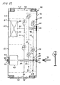
- FIG. 34 shows a schematic diagram of a drive 10 with electric motor 50 and dreikettrigem transmission 100 with oil seal for a small vehicle according to an embodiment of the application.
- the electric motor 50 and the transmission 100 are arranged in a three-part housing 42, protruding from both sides of an output shaft 34 as a bottom bracket shaft 30.
- the housing 42 has a housing middle part 45 which is open on both sides and which is closed on both sides by a first and a second housing cover 43 or 44 in a media-tight manner.
- the transmission is a three-gear transmission 100, ie the transmission 100 is designed with three chains 11, 12 and 13.
- a first portion 85 is provided, which is protected from chain oil, in which the electric motor 50, a freewheel 40, a measuring wheel 49 and the output shaft 34 are arranged as a bottom bracket shaft 30.
- a second region 95 is sealed off from the first region 85 within the housing 42 by a partition wall 82 and has the three chain drives of three reduction stages 21, 22 and 23 with the chains 11, 12 and 13. In the second region 95, a chain oil is provided for the three chain drives.
- the motor shaft 31 projects through the partition wall 82 into the second region 95 and is sealed with a first sealing ring 91.
- the second region 95 has a double hollow shaft with an inner hollow shaft 68 and an outer hollow shaft 69, which are mounted on the bottom bracket 30 and protect the bottom bracket shaft 30 and the first portion 85 from chain oil with three further seals.
- the outer hollow shaft extends to the partition wall 82.
- a second sealing ring 92 is disposed between the outer hollow shaft 69 and the partition wall 82.
- the inner hollow shaft extends from the freewheel 40 to the second housing cover 44.
- a third sealing ring 93 is provided between the outer and the inner hollow shaft 69 and 68, respectively.
- a fourth sealing ring 94 is disposed between the inner hollow shaft 68 and the second housing cover 44.
- the relatively low motor torque due to a ring gear ratio of a first drive gear 1 on the motor shaft 31 to a first output gear 2 on the outer hollow shaft 69 increased by a factor of 75/21 to a higher torque of the outer hollow shaft 69, and reduces the speed of the outer hollow shaft 69 by the same factor.
- the second reduction stage 22 since the reduction ratio of the first reduction stage 21 is equal to the reduction ratio of the second reduction stage 22, the second reduction stage 22 further increases the torque by the same factor and further reduces the rotation speed of an intermediate shaft 33 by the same factor.
- the torque is increased with the third reduction stage 23 due to a ring gear ratio of a third drive gear 5 on the intermediate shaft 33 to a third output gear 6 on the inner hollow shaft 68 again by a factor of 57/21, so that an output torque through the inner hollow shaft 68 and the freewheel 40 on the bottom bracket 30 is available.
- the output torque is higher by a factor of about 35 than the engine torque and is sufficient to transmit an adapted starting torque to a small vehicle impeller.
- the output speed of the bottom bracket 30 is reduced by the total reduction of the transmission of about 35 relative to the engine speed.
- FIG. 34 embodiment shown has the advantage that by dividing the housing 42 in a first region 85 and a second region 95 by inserting a partition wall 82, only the chain drive with the chains 11, 12 and 13 are supplied with chain oil, wherein four sealing rings 91 to 94 be sufficient that the first area 85 and the bottom bracket with pedal bearings are protected from chain oil.
- the outer hollow shaft is extended to the partition wall 82 while extending an extended inner hollow shaft of the freewheel 40 to the second housing cover 44.
- the structure of the drive with closed oil chamber is in itself relevant and identifiable as a separate item in itself, especially in the context of the dreikettrigen transmission.
- the combination with a triple hollow shaft is relevant, wherein the pinion 7 is arranged using a freewheel on the inner hollow shaft, so that the driver does not have to go with it when the electric motor drives.
- FIG. 35 shows a schematic diagram of a drive 10 with electric motor 50 and transmission for a small vehicle according to an embodiment of the application.
- the electric motor 50 and the transmission are arranged in a housing 42 from which an output shaft 34 protrudes on one side.
- the transmission is designed as dreikettriges transmission, ie as a transmission with three chains 11, 12 and 13.
- a first reduction stage 21 has a first pinion 1, which is fixed on a motor shaft 31 of the electric motor 50.
- the first pinion 1 is mechanically connected via a first chain 11 to a first driven gear 2, which is arranged on a first intermediate shaft 32.
- a second reduction stage 22 has a second pinion 3, which is fixed on the first intermediate shaft 32 together with the first output gear 2.
- the second pinion 3 is mechanically connected via a second chain 12 to a second driven gear 4, which is fixed on a second intermediate shaft 33.
- a third reduction stage 23 has a third pinion 5 which is fixed on the second intermediate shaft 33 together with the second output gear 4.
- the third pinion 5 is mechanically connected via a third chain 13 to a third driven gear 6, wherein the third driven gear 6 is fixed on the output shaft 34 of the drive 10.
- the motor shaft 31 and the second intermediate shaft 33 are provided in alignment with each other.
- the output shaft 34 and the first intermediate shaft 32 are also aligned with each other.
- the pinions 1, 3 and 5 have in the illustrated gear on the same number 21 of teeth.
- the output gears 2 and 4 have an equal number 75 of teeth.
- the relatively low engine torque is increased by a factor of 75/21 to a higher torque of the first intermediate shaft 32, and the speed of the first intermediate shaft 32 is reduced by the same factor.
- the second reduction stage 22 since the reduction ratio of the first reduction stage 21 is equal to the reduction ratio of the second reduction stage 22, the second reduction stage 22 further increases the torque by the same factor and further reduces the rotation speed of the second intermediate shaft 33 by the same factor.
- the torque with the third reduction stage 23 is again increased by a factor 57/21, so that an output torque is available which is higher by a factor of about 35 than the engine torque.
- the shafts 32 to 34 with the hubs 15 to 19 of the gears 2 to 6 non-positively, material or positively connected To transmit the torques from the motor shaft 31 to the output shaft 34, the shafts 32 to 34 with the hubs 15 to 19 of the gears 2 to 6 non-positively, material or positively connected.
- the output shaft 34 carries on the protruding from the housing 42 end an output pinion 7, which transmits via a chain drive 14, a starting torque via a hub gear 41 to an impeller 26 of the small vehicle. In this case, the output speed of the output pinion 34 is reduced by the total reduction of the transmission of about 35 relative to the engine speed.
- FIG. 36 shows a schematic diagram of a pinion hub for a dreikettriges transmission.
- the pinion 1 has a polygonal hub opening 27, which is connected in a form-fitting manner to the shaft for transmitting torque on a correspondingly adapted shaft stage with the same polygonal profile.
- the ring gear 9 of the pinion 1 is arranged opposite to the hub opening 27 of the pinion 1 such that each corner 84 of the polygonal hub opening 27 faces a tooth root 86.
- FIG. 2 shows, between two adjacent corners of the polygonal hub opening 29 three teeth 87 of the ring gear 9 are arranged so that in the illustrated pinion 1 with a hub opening 27 with seven corners 84 a sprocket 9 with 21 teeth 87 an optimal match between the respective corner 84 and one Zahnfußmitte 83 is present.
- the pinions 3 and 5 are executed, especially since the pinions 3 and 5 have the same number of teeth 21 as the pinion. 1
- a sprocket for the chain drive which reduces weakening of a pinion with polygonal hub opening in that the number of corners and the number of teeth are coordinated and aligned with each other, that each corner of the polygonal hub opening is disposed opposite a satinfuß.
- the corners of the polygonal hub opening are aligned exactly in the middle of each tooth root.
- the pinion shown has an odd number of teeth on the ring gear, so that the frequency of impact of a chain link of the chain is reduced to the same tooth of the ring gear.
- Another advantage of the pinion shown is that a theoretical minimum number of teeth is not exceeded, so that the noise is negligible.
- the number of teeth per sprocket of pinions 1, 3 and 5 should not fall below a minimum number and may be between 19 and 25, preferably between 19 to 23 without a noise development dominates.
- the number of teeth per sprocket of the output gears of the reduction stages 21, 22 and 23 can be between 45 and 85 without the wrap angle of the chains on the associated driven gears is too low. This allows an improved range of the reduction ratios without serious changes in the space required for the drive.
- the structure of the pinion 1 is individually relevant and identifiable as a separate item in itself, especially in connection with the dreikettrigen transmission.
- FIG. 37 shows a schematic diagram of a drive 10 with electric motor 50 and transmission for a small vehicle according to an embodiment of the application.
- the electric motor 50 and the transmission are arranged in a housing 42 from which an output shaft 34 protrudes on one side.
- the transmission is designed as dreikettriges transmission, ie as a transmission with three chains 11, 12 and 13.
- the speed of the motor shaft 31 is reduced to the speed of a freewheel shaft 39.
- the freewheel shaft is connected via a freewheel 40 with the output shaft 34 in connection, which rotates at the same speed as soon as the freewheel on the output shaft 34 is stuck.
- a measuring wheel 49 is arranged, with which the rotational speed of the output shaft 34 is detected by a sensor 88.
- the space is used, which is available below the electric motor 50, so that the speed measurement does not have to be outside of the housing 42.
- the sensor 88 Via a measuring line 96 within the housing 42, the sensor 88 is connected to an electrical connection region 67 of the electric motor 50 in connection.
- An external measuring line 97 connects the electrical connection region 67 to a control device 90, to which a display 89 is connected via a display line 98.
- the measuring wheel 49 detects the rotational speed via the sensor 88.
- the measured values are conducted via the internal line 96 to the electrical connection region 67.
- the measured values are supplied to a control unit 90 and evaluated.
- Via a display line 98 the data is fed to a display 89 and displayed on a customer-specific basis.
- the relatively low engine torque is increased by a factor of 75/21 to a higher torque of a first intermediate shaft 32, and the speed of a first intermediate shaft 32 is reduced by the same factor.
- the second reduction stage 22 since the reduction ratio of the first reduction stage 21 is equal to the reduction ratio of the second reduction stage 22, the second reduction stage 22 further increases the torque by the same factor and the rotation speed of a second intermediate shaft 33 decreased by the same factor.
- the torque with the third reduction stage 23 is again increased by a factor 57/21, so that an output torque is available which is higher by a factor of about 35 than the engine torque. In this case, the output speed of the output shaft 35 is reduced by the total reduction of the transmission of about 35 relative to the engine speed.
- Figure 38 shows a schematic diagram of a measuring wheel 49 for optical speed sensing.
- the measuring wheel 49 on its circumference evenly distributed covering teeth 101.
- the covering teeth 101 cover an optical transmitter 99 radiating in the axial direction, for example a light barrier.
- measuring signals are passed to the control unit and evaluated.
- the measurement signals trigger control functions in the control unit and provide status information of the output shaft.
- FIG. 39 shows a schematic diagram of a measuring wheel 49 for electromagnetic Drehiereabtastung with a Hall sensor 103.
- 101 permanent magnetic plates 104 are arranged on the cover teeth, which are detected by the Hall sensor 103 when passing the measuring wheel 49 without contact.
- the Hall sensor 103 supplies voltage pulses, which are transmitted as measurement signals to the control unit.
- the embodiment according to FIG. 37 has the advantage that an optical and an electromagnetic detection does not take place outside of the drive, but within the drive housing, the free space below the electric motor is used for a protected against environmental influences measurement.
- the embodiment according to FIG. 37 (Optical speed detection) has the advantage that also inexpensive plastic wheels can be used as a measuring wheel.
- the embodiment according to Figure 38 requires permanent magnetic plates, which can trigger a Hall signal. This has the advantage that this sensor does not require an optical sight to deliver measurement signals.
- the RPM scan is relevant in itself and identifiable as a separate item in itself, especially in the context of the tri-squared gearbox.
- the combination with a triple hollow shaft is relevant, wherein the pinion 7 is arranged using a freewheel on the inner hollow shaft 39, so that the driver does not have to go with it when the electric motor drives.
Description
Die vorliegende Anmeldung betrifft Getriebeeinheiten für Fahrzeuge und Fahrzeuge, insbesondere Fahrräder, die sowohl mit Muskelkraft als auch mit einem Motor, insbesondere einem elektrischen Motor, angetrieben werden. Fahrräder, die mit einem elektrischen Hiltsmotor ausgestattet sind, werden auch als Elektrofahrrad bezeichnet. Daneben betrifft die Anmeldung Fahrzeuge wie Boote, z.B. Tretboote.The present application relates to transmission units for vehicles and vehicles, in particular bicycles, which are driven both by muscle power and with a motor, in particular an electric motor. Bicycles equipped with an electric power motor are also referred to as electric bicycles. In addition, the application relates to vehicles such as boats, e.g. Pedal boats.
Man unterscheidet grundsätzlich zwei Typen von Elektrofahrrädern, nämlich das E-Bike und das Pedelec. Beim E-Bike wird der Molor unabhängig von der Treileistung des Fahrrads gesteuert, dass heißt Fahren ist auch ohne Treten möglich. Dabei wird die Motorleistung über ein manuelles Bedienelement - einen Drehgriff oder Knopf-geregelt, wie das von Mopeds bereits bekannt ist. Muskelkraft und Motor sind unabhängig voreinander wirkende Systeme. E-Bikes können sowohl rein elektrisch wie auch im Mischbetrieb gefahren werden.There are basically two types of electric bicycles, namely the e-bike and the pedelec. When e-bike, the Molor is controlled regardless of the performance of the bike, that is driving is possible without pedaling. The engine power is controlled by a manual control - a knob or knob, as is already known by mopeds. Muscle strength and motor are independently interacting systems. E-bikes can be driven either purely electrically or in mixed operation.
Beim Pedelec hingegen funktioniert die Hilfsantriebsunterstützung nur dann, wenn gleichzeitig getreten wird. In der Regel wird dabei bis zur einer bestimmten Höchstgeschwindigkeit ein Teil der vom Fahrer erbrachten Leistung durch den Hillsantrieb ergänzt. Die Motorleistung wird dabei über einen Kraft- bzw. Bewegungssensor automatisch an die Muskelkraft des Fahrers gekoppelt.On the pedelec, on the other hand, auxiliary drive assistance only works when pedaling at the same time. As a rule, up to a certain maximum speed, part of the driver's power is supplemented by the Hills drive. The engine power is automatically coupled via a force or motion sensor to the muscle power of the driver.
Die Anmeldung stellt gemäß einem Aspekt ein Getriebe bereit, bei dem Muskelkraft und Elektroantrieb auf einfache Weise miteinander kombiniert werden können.According to one aspect, the application provides a transmission in which muscle power and electric drive can be easily combined with one another.
Die Getriebeeinheit der Anmeldung ist für ein sowohl mit Menschenkraft - also manuell oder auch peduell d.h. mit Pedalen angetrieben - als auch mit einem Elektromotor angetriebenes Fahrzeug, wobei das Getriebe eine durch Menschenkraft betätigbare Kurbelwelle zum Anschluß an eine erste Antriebsvorrichtung mit Kurbeln und Pedalen und eine davon separate Eingangswelle zum Anschluß an eine Rotorwelle eines Elektromotors aufweist. Das dort eingebrachte Drehmoment wird von der Getriebeeinheit an eine Ausgangswelle übertragen, die zum Anschluß an ein Abtriebselement z.B. Kettenrad, Riemenscheibe, Ausgangswelle, etc. eines Fahrzeugs bestimmt ist.The transmission unit of the application is for a both human power - ie manually or pedally driven ie with pedals - as well as with an electric motor driven vehicle, wherein the transmission is a crankshaft operable by human power for connection to a first drive device with cranks and pedals and a separate input shaft for connection to a rotor shaft of an electric motor. The torque introduced there is transmitted by the gear unit to an output shaft, which is intended for connection to an output element such as sprocket, pulley, output shaft, etc. of a vehicle.
Irgendwo im Kraftfluß oder auch speziell direkt zwischen der Kurbelwelle und der Ausgangswelle kann eine erste Freilaufeinrichtung vorgesehen sein, die ein erstes Einleitungselement aufweist, das direkt oder indirekt, fest oder lösbar mit der Eingangswelle in Verbindung stehen kann. Ein erstes Ausleitungselement kann direkt oder indirekt sowie fest oder lösbar mit der Ausgangswelle in Verbindung stehen.Somewhere in the power flow or especially directly between the crankshaft and the output shaft may be provided a first freewheel device having a first introduction element, which may be directly or indirectly, fixed or releasably connected to the input shaft. A first diverting element may be directly or indirectly and permanently or detachably connected to the output shaft.
Irgendwo im Kraftfluß oder auch speziell direkt zwischen der Eingangswelle und der Ausgangswelle eine zweite Freilaufeinrichtung vorgesehen ist, die ein zweites Einleitungselement aufweist, das direkt oder indirekt, fest oder lösbar mit der Kurbelwelle in Verbindung stehen kann. Außerdem hat es ein zweites Ausleitungselement, das direkt oder indirekt bzw. fest oder lösbar mit der Ausgangswelle in Verbindung steht. Das erste Ausleitungselement und das zweite Ausleitungselement sind permanent miteinander verbunden und zwar im wesentlichen ohne Kupplung im Kraftfluss, also entweder über Übertragungselemente des Untersetzungsgetriebes oder direkt. Ferner sind zwischen der Eingangswelle und der Ausgangswelle ein dreistufiges Untersetzungsgetriebe vorgesehen ist. Bei dem Getriebe untersetzt in jeder Getriebestufe. Insgesamt sind drei Untersetzungsstufen mit jeweils zwei Zahnrädern vorgesehen, wobei die Untersetzungsstufen jeweils ein Abtriebszahnrad und ein Antriebszahnrad aufweisen. Davon ist ein Abtriebszahnrad einer ersten Untersetzungsstufe konzentrisch zu einer Achse der Eingangswelle angeordnet und ein Abtriebszahnrad der ersten Untersetzungsstufe, ein Antriebszahnrad der zweiten Untersetzungsstufe und ein Abtriebszahnrad der dritten Untersetzungsstufe sind konzentrisch zu der Kurbelwelle angeordnet. Die erste Untersetzungsstufe befindet sich im Kraftfluss zwischen dem Elektromotor und dem ersten Einleitungselement und die zweite Untersetzungsstufe und die dritte Untersetzungsstufe sind im Kraftfluss zwischen dem ersten Ausleitungselement der ersten Freilaufeinrichtung und dem zweiten Einleitungselement der zweiten Freilaufeinrichtung angeordnet.Somewhere in the power flow or specifically directly between the input shaft and the output shaft, a second freewheel device is provided, which has a second introduction element, which can be directly or indirectly, fixed or releasably connected to the crankshaft. In addition, it has a second discharge element which is directly or indirectly or permanently or detachably connected to the output shaft. The first diverting element and the second diverting element are permanently connected to one another and indeed essentially without a coupling in the force flow, that is to say either via transmission elements of the reduction gear or directly. Further, a three-stage reduction gear is provided between the input shaft and the output shaft. In the gearbox stocky in each gear stage. Overall, three reduction stages are provided with two gears, the reduction stages each having a driven gear and a drive gear. Of these, an output gear of a first reduction stage is disposed concentrically with an axis of the input shaft, and a first-reduction stage output gear, a second reduction stage drive gear, and a third reduction stage output gear are disposed concentrically with the crankshaft. The first reduction stage is located in the power flow between the electric motor and the first introduction element and the second reduction stage and the third reduction stage are arranged in the power flow between the first discharge element of the first freewheel device and the second introduction element of the second freewheel device.
Eine solche Getriebeeinheit lässt sich kompakt und einfach aufbauen, wobei die beiden Freiläufe eine komfortable Benutzung gestattet.Such a gear unit can be compact and easy to build, the two freewheels allows comfortable use.
Eine einfache Konstruktion ergibt sich, wenn das erste Einleitungselement als Außenring der ersten Freilaufeinrichtung ausgebildet ist und wenn das erste Ausleitungselement als Innenring der ersten Freilaufeinrichtung ausgebildet ist. Weiterhin sollte dann das zweite Einleitungselement als Außenring der zweiten Freilaufeinrichtung ausgebildet sein und das zweite Ausleitungselement als Innenring der zweiten Freilaufeinrichtung ausgebildet sein.A simple construction results when the first introduction element is designed as an outer ring of the first freewheel device and when the first discharge element is designed as an inner ring of the first freewheel device. Furthermore, then should the second introduction element may be formed as an outer ring of the second freewheel device and the second discharge element may be formed as an inner ring of the second freewheel device.
Man kann reibungsarme Zentrifugalfreilaufe einsetzen, wenn das erste Einleitungselement als Außenring der ersten Freilaufeinrichtung ausgebildet ist und wenn das erste Ausleitungselement als Innenring der ersten Freilaufeinrichtung ausgebildet ist, wobei ferner das zweite Einleitungselement als Innenring der zweiten Freilaufeinrichtung ausgebildet ist und das zweite Ausleitungselement als Außenring der zweiten Freilaufeinrichtung ausgebildet ist.One can use low-friction centrifugal freewheel when the first introduction element is formed as an outer ring of the first freewheel device and when the first discharge element is formed as an inner ring of the first freewheel device, further wherein the second introduction element is formed as an inner ring of the second freewheel device and the second discharge element as the outer ring of the second Freewheel device is formed.
Ein kompakter Aufbau der Getriebeeinheit ergibt sich, wenn das Abtriebszahnrad der ersten Untersetzungsstufe und das Antriebszahnrad der zweiten Untersetzungsstufe auf einer gemeinsamen Hohlwelle gelagert sind und wenn das Abtriebszahnrad der zweiten Untersetzungsstufe und das Antriebszahnrad der dritten Untersetzungsstufe auf einer gemeinsamen Welle gelagert sind. Dabei können das Abtriebszahnrad der ersten Untersetzungsstufe und das Antriebszahnrad der zweiten Untersetzungsstufe mittels einer ersten Lagerung gelagert sein, wobei das Abtriebszahnrad der zweiten Untersetzungsstufe und das Antriebszahnrad der dritten Untersetzungsstufe mittels einer zweiten Lagerung gelagert sind. Ein kompakter Aufbau wird begünstigt, wenn die erste Lagerung und die zweite Lagerung jeweils als zwei entgegengesetzt orientierte Schräglager ausgebildet sind, insbesondere als sogenannte O-Lagerung, bei der ein Zahnrad außerhalb der beiden Lagerstellen angeordnet werden kann. Zusätzlich kann dann die Abtriebswelle als innere Hohlwelle ausgebildet sein, wobei das Abtriebszahnrad der ersten Untersetzungsstufe und das Antriebszahnrad der zweiten Untersetzungsstufe auf einer äußeren Hohlwelle angeordnet sind, die drehbar auf der inneren Hohlwelle angeordnet ist.A compact construction of the gear unit results when the output gear of the first reduction stage and the drive gear of the second reduction stage are mounted on a common hollow shaft and when the output gear of the second reduction stage and the drive gear of the third reduction stage are mounted on a common shaft. In this case, the output gear of the first reduction stage and the drive gear of the second reduction stage may be supported by a first bearing, wherein the output gear of the second reduction stage and the drive gear of the third reduction stage are supported by a second bearing. A compact design is favored when the first bearing and the second bearing are each formed as two oppositely oriented angular contact bearings, in particular as so-called O-bearing, in which a gear can be arranged outside of the two bearings. In addition, then the output shaft may be formed as an inner hollow shaft, wherein the output gear of the first reduction stage and the drive gear of the second reduction stage are arranged on an outer hollow shaft which is rotatably mounted on the inner hollow shaft.
In einer besonderen Ausgestaltung ist die zweite Freilaufeinrichtung an einem Ende der inneren Hohlwelle zwischen der Hohlwelle und der Kurbelwelle angeordnet, wobei die erste Freilaufeinrichtung zwischen dem Abtriebszahnrad der ersten Untersetzungsstufe und der äußeren Hohlwelle angeordnet sein kann. Dadurch wird die Gestaltungsfreiheit, die sich aus einer Verwendung einer Hohlwelle ergibt, vorteilhaft angewendet.In a particular embodiment, the second freewheel device is arranged at one end of the inner hollow shaft between the hollow shaft and the crankshaft, wherein the first freewheel device between the output gear of the first reduction stage and the outer hollow shaft can be arranged. As a result, the freedom of design resulting from the use of a hollow shaft, applied advantageous.
Die innere Hohlwelle kann auch als Ausgangswelle zur Verbindung mit einem Abtriebsrad für eine Abtriebsstufe des Fahrzeugs ausgebildet sein.The inner hollow shaft can also be designed as an output shaft for connection to a driven gear for an output stage of the vehicle.
Eine günstige Lagerung ergibt sich, wenn die innere Hohlwelle an einer Seite in einem Gehäuse der Getriebeeinheit gelagert ist. Auf der anderen Seite ist die Kurbelwelle in dem Gehäuse der Getriebeeinheit gelagert. Die Kurbelwelle ist an der gegenüberliegenden Seite in der inneren Hohlwelle gelagert.A favorable storage results when the inner hollow shaft is mounted on one side in a housing of the transmission unit. On the other hand, the crankshaft is mounted in the housing of the gear unit. The crankshaft is mounted on the opposite side in the inner hollow shaft.
Die Getriebeeinheit hat in wenigstens einer Untersetzungsstufe eine Rollenkette oder einen Zahnriemen. Alternativ dazu sind auch Zahnräder, die direkt ineinander eingreifen möglich, also schräg oder gerade verzahnt.The gear unit has a roller chain or a toothed belt in at least one reduction stage. Alternatively, gears that mesh directly with each other possible, so obliquely or straight toothed.
Besonders günstig ist es, wenn die Getriebeeinheit mit wenigstens einer Zentrifugalfreilaufeinrichtung versehen ist. Dadurch ergeben sich geringe Reibungskräfte, was typisch ist für eine Freilaufeinrichtung, die unter Zuhilfenahme von Zentrifugalkräften aktiviert wird bzw. sperrt.It is particularly favorable if the gear unit is provided with at least one centrifugal freewheel device. This results in low frictional forces, which is typical for a freewheel device that is activated or blocked with the aid of centrifugal forces.
Die Anmeldung umfasst auch ein Fahrzeug mit einer solchen Getriebeeinheit, wobei die Ausgangswelle mit einem Laufrad des Fahrzeugs verbunden ist und wobei die Eingangswelle mit einem Elektromotor verbunden ist. Man kann sich dabei ein Elektrofahrrad oder einen Rollstuhl vorstellen.The application also includes a vehicle having such a transmission unit, wherein the output shaft is connected to an impeller of the vehicle and wherein the input shaft is connected to an electric motor. You can imagine an electric bicycle or a wheelchair.
Die Ausführungsformen der vorliegenden Anmeldung werden im folgenden unter Bezugnahme auf Figuren näher erläutert.
Figur 1- zeigt eine Prinzipskizze mehrerer Ausführungsbeispiele einer MotorGetriebe Einheit mit doppeltem Freilauf und Kettengetriebe,
Figur 2- zeigt eine Prinzipskizze eines Ausführungsbeispiels einer Motor Getriebe Einheit gemäß
Fig. 1 , Figur 3- zeigt eine Explosionszeichnung der Ausführungsform von
Fig. 2 , Figur 4- zeigt eine detaillierte Schnittzeichnung des Getriebes von
Figur 1 Figur 5- zeigt eine Prinzipskizze eines weiteren Ausführungsbeispiels einer Motor Getriebe Einheit gemäß
Fig. 1 , Figur 5- zeigt eine Prinzipskizze eines weiteren Ausführungsbeispiels einer Motor Getriebe Einheit gemäß
Fig. 1 , Figur 6- zeigt eine Prinzipskizze eines weiteren Ausführungsbeispiels einer Motor Getriebe Einheit gemäß
Fig. 1 , Figur 7- zeigt eine Prinzipskizze eines weiteren Ausführungsbeispiels einer Motor Getriebe Einheit gemäß
Fig. 1 , Figur 8- zeigt eine Prinzipskizze eines weiteren Ausführungsbeispiels einer Motor Getriebe Einheit gemäß
Fig. 1 , Figur 9- zeigt eine Prinzipskizze eines weiteren Ausführungsbeispiels einer Motor Getriebe Einheit gemäß
Fig. 1 , Figur 10- zeigt eine Prinzipskizze eines weiteren Ausführungsbeispiels einer Motor Getriebe Einheit gemäß
Fig. 1 , Figur 11- zeigt eine Prinzipskizze eines weiteren Ausführungsbeispiels einer Motor Getriebe Einheit gemäß
Fig. 1 , Figur 12- zeigt eine Prinzipskizze eines Antriebs mit Elektromotor und Getriebe für ein Kleinfahrzeug,
Figur 13- zeigt eine weitere Prinzipskizze eines Antriebs mit Elektromotor und Getriebe für ein Kleinfahrzeug,
Figur 14- zeigt eine weitere Prinzipskizze eines Antriebs mit Elektromotor und Getriebe für ein Kleinfahrzeug,
Figur 15- zeigt eine schematische Darstellung einer Lagerung einer Zwischenwelle in
Figur 14 Figur 16- zeigt eine Prinzipskizze eines weiteren Antriebs mit Elektromotor und Getriebe für ein Kleinfahrzeug,
- Figur 17
- zeigt schematische Darstellungen von unterschiedlichen Nabenformen von Zahnrädern des Getriebes aus
Fig. 16 , Figur 18- zeigt schematische Darstellungen von unterschiedlichen Nabenformen mit aufgeklebten Zahnrädern des Getriebes aus
Fig. 16 und17 , Figur 19- zeigt eine Prinzipskizze eines weiteren Antriebs mit Elektromotor und Getriebe für ein Kleinfahrzeug;
Figur 20- zeigt eine Prinzipskizze eines weiteren Antriebs mit Elektromotor und Getriebe für ein Kleinfahrzeug,
Figur 21- zeigt eine Prinzipskizze eines weiteren Antriebs mit Elektromotor und Getriebe für ein Kleinfahrzeug,
Figur 22- zeigt eine Prinzipskizze eines weiteren Antriebs mit Elektromotor und Getriebe für ein Kleinfahrzeug,
Figur 23- zeigt eine Prinzipskizze eines weiteren Antriebs mit Elektromotor und Getriebe für ein Kleinfahrzeug,
Figur 24- zeigt eine Prinzipskizze eines Zweirads mit einer Schwinge für ein Laufrad und mit Elektromotor sowie Getriebe,
Figur 25- zeigt einen schematischen Querschnitt durch das Zweirad in
Figur 24 Figur 26- zeigt eine Prinzipskizze eines ersten Gehäusedeckels eines weiteres Ausführungsbeispiel, an dem erste Zahnräder eines dreiteiligen Antriebsgehäuses gemäß eines ersten Ausführungsbeispiels angeordnet sind,
Figur 27- zeigt eine Prinzipskizze von weiteren drei Zahnrädern eines Gehäusemittelteils des dreiteiligen Antriebsgehäuses gemäß
Figur 26 , Figur 28- zeigt eine Prinzipskizze des dreiteiligen Antriebsgehäuses nach Zusammenbau des ersten Gehäusedeckels mit dem Gehäusemittelteil und einem zweiten Gehäusedeckel,
Figur 29- zeigt eine Prinzipskizze des dreiteiligen Antriebsgehäuses nach Einbau in einen Zweiradrahmen,
Figur 30- zeigt eine Prinzipskizze eines ersten Gehäusedeckels, an dem erste Zahnräder eines dreiteiligen Antriebsgehäuses gemäß eines zweiten Ausführungsbeispiels angeordnet sind,
Figur 31- zeigt eine Prinzipskizze von weiteren drei Zahnrädern eines Gehäusemittelteils des dreiteiligen Antriebsgehäuses gemäß
Figur 30 , Figur 32- zeigt eine Prinzipskizze eines dreiteiligen Antriebsgehäuses nach Zusammenbau des ersten Gehäusedeckels mit dem Gehäusemittelteil und einem zweiten Gehäusedeckel,
Figur 33- zeigt eine Prinzipskizze des dreiteiligen Antriebsgehäuses nach Einbau in einen Zweiradrahmen,
Figur 34- zeigt eine Prinzipskizze eines weiteren Antriebs mit Elektromotor und dreikettrigem Getriebe mit Ölabdichtung,
Figur 35- zeigt eine Prinzipskizze eines weiteren Antriebs mit Elektromotor und Getriebe gemäß einem Ausführungsbeispiel der Anmeldung,
Figur 36- zeigt eine Prinzipskizze einer Ritzelnabe für ein dreikettriges Getriebe gemäß
Fig. 35 , Figur 37- zeigt eine Prinzipskizze eines Antriebs mit Elektromotor und Getriebe gemäß einem Ausführungsbeispiel der Anmeldung;
Figur 38- zeigt eine Prinzipskizze eines Messrades zur optischen Drehzahlabtastung;
Figur 39- zeigt eine Prinzipskizze eines Messrades zur elektromagnetischen Drehzahlabtastung.
- FIG. 1
- shows a schematic diagram of several embodiments of a motor-gear unit with double freewheel and chain transmission,
- FIG. 2
- shows a schematic diagram of an embodiment of a motor gear unit according to
Fig. 1 . - FIG. 3
- shows an exploded view of the embodiment of
Fig. 2 . - FIG. 4
- shows a detailed sectional view of the transmission of
FIG. 1 . - FIG. 5
- shows a schematic diagram of another embodiment of a motor gear unit according to
Fig. 1 . - FIG. 5
- shows a schematic diagram of another embodiment of a motor gear unit according to
Fig. 1 . - FIG. 6
- shows a schematic diagram of another embodiment of a motor gear unit according to
Fig. 1 . - FIG. 7
- shows a schematic diagram of another embodiment of a motor gear unit according to
Fig. 1 . - FIG. 8
- shows a schematic diagram of another embodiment of a motor gear unit according to
Fig. 1 . - FIG. 9
- shows a schematic diagram of another embodiment of a motor gear unit according to
Fig. 1 . - FIG. 10
- shows a schematic diagram of another embodiment of a motor gear unit according to
Fig. 1 . - FIG. 11
- shows a schematic diagram of another embodiment of a motor gear unit according to
Fig. 1 . - FIG. 12
- shows a schematic diagram of a drive with electric motor and transmission for a small vehicle,
- FIG. 13
- shows a further schematic diagram of a drive with electric motor and transmission for a small vehicle,
- FIG. 14
- shows a further schematic diagram of a drive with electric motor and transmission for a small vehicle,
- FIG. 15
- shows a schematic representation of a storage of an intermediate shaft in
FIG. 14 . - FIG. 16
- shows a schematic diagram of another drive with electric motor and transmission for a small vehicle,
- FIG. 17
- shows schematic representations of different hub shapes of gears of the transmission
Fig. 16 . - FIG. 18
- shows schematic representations of different hub shapes with glued gears of the transmission
Fig. 16 and17 . - FIG. 19
- shows a schematic diagram of another drive with electric motor and transmission for a small vehicle;
- FIG. 20
- shows a schematic diagram of another drive with electric motor and transmission for a small vehicle,
- FIG. 21
- shows a schematic diagram of another drive with electric motor and transmission for a small vehicle,
- FIG. 22
- shows a schematic diagram of another drive with electric motor and transmission for a small vehicle,
- FIG. 23
- shows a schematic diagram of another drive with electric motor and transmission for a small vehicle,
- FIG. 24
- shows a schematic diagram of a two-wheeler with a rocker for an impeller and with electric motor and transmission,
- FIG. 25
- shows a schematic cross section through the bicycle in
FIG. 24 . - FIG. 26
- shows a schematic diagram of a first housing cover of a further embodiment, are arranged on the first gears of a three-piece drive housing according to a first embodiment,
- FIG. 27
- shows a schematic diagram of another three gears of a middle part of the housing of the three-piece drive housing according to
FIG. 26 . - FIG. 28
- shows a schematic diagram of the three-piece drive housing after assembly of the first housing cover with the housing middle part and a second housing cover,
- FIG. 29
- shows a schematic diagram of the three-piece drive housing after installation in a bicycle frame,
- FIG. 30
- shows a schematic diagram of a first housing cover, are arranged on the first gears of a three-piece drive housing according to a second embodiment,
- FIG. 31
- shows a schematic diagram of another three gears of a middle part of the housing of the three-piece drive housing according to
FIG. 30 . - FIG. 32
- shows a schematic diagram of a three-piece drive housing after assembly of the first housing cover with the housing middle part and a second housing cover,
- FIG. 33
- shows a schematic diagram of the three-piece drive housing after installation in a bicycle frame,
- FIG. 34
- shows a schematic diagram of another drive with electric motor and dreikettrigem transmission with oil seal,
- FIG. 35
- shows a schematic diagram of another drive with electric motor and transmission according to an embodiment of the application,
- FIG. 36
- shows a schematic diagram of a pinion hub for a dreikettriges transmission according to
Fig. 35 . - FIG. 37
- shows a schematic diagram of a drive with electric motor and transmission according to an embodiment of the application;
- Figure 38
- shows a schematic diagram of a measuring wheel for optical speed sensing;
- FIG. 39
- shows a schematic diagram of a measuring wheel for electromagnetic speed sensing.
In der nachfolgenden Beschreibung sind zahlreiche Ausführungsbeispiele sehr detailliert beschrieben. Dies erfolgte zur besseren Erklärung der beiliegenden Figuren. Ungeachtet dessen umfasst die Anmeldung auch Merkmalskombinationen, die nur einen Teil der Merkmale der Ausführungsbeispiele aufweisen. Wenn also mehrere Merkmale zusammen beschrieben werden, dann impliziert dies, daß auch nur einzelne dieser Merkmale für sich zusammen gesehen einen sinnvollen Teilzusammenhang ergeben.In the following description, numerous embodiments are described in great detail. This was done to better explain the accompanying figures. Regardless, the application also includes feature combinations having only a portion of the features of the embodiments. Thus, describing several features together implies that only a few of these features, taken together, provide a meaningful sub-context.
Teile in
Dazu weist eine erste Untersetzungsstufe 21 ein erstes Antriebszahnrad 1 auf, das auf einer Motorwelle 31 des Elektromotors 50 fixiert ist. Das erste Antriebszahnrad 1 ist mechanisch über die erste Kette 11 mit einem ersten Abtriebszahnrad 2 drehbar verbunden, das konzentrisch um eine erste Zwischenwelle 32 angeordnet ist. Die erste Zwischenwelle 32 ist als Hohlwelle ausgebildet, die konzentrisch zur Tretwelle 34 angeordnet ist.For this purpose, a
Die zweite Untersetzungsstufe 22 weist ein zweites Antriebszahnrad 3 auf, das konzentrisch um die erste Zwischenwelle 32 angeordnet ist. Das zweite Antriebszahnrad 3 ist mechanisch über die zweite Kette 12 mit einem zweiten Abtriebszahnrad 4 drehbar verbunden, das auf einer zweiten Zwischenwelle 33 fixiert ist.The
Die dritte Untersetzungsstufe 23 weist ein drittes Antriebszahnrad 5 auf, das auf der zweiten Zwischenwelle 33 zusammen mit dem zweiten Abtriebszahnrad 4 fixiert ist. Das dritte Antriebszahnrad 5 ist mechanisch über die dritte Kette 13 mit einem dritten Abtriebszahnrad 6 drehbar verbunden. Das dritte Abtriebszahnrad 6 ist konzentrisch um eine Abtriebswelle 35 angeordnet. Die Abtriebswelle 35 ist als Hohlwelle ausgebildet, die konzentrisch zur Tretwelle 34 gelagert ist.The
Das Abtriebszahnrad 2 der ersten Untersetzungsstufe 21 und das Antriebszahnrad 1 der Motorwelle 31 sind in einer Ebene der ersten Untersetzungsstufe angeordnet, das Antriebszahnrad 3 und das Abtriebszahnrad 4 der zweiten Untersetzungsstufe 22 sind in einer Ebene der zweiten Untersetzungsstufe 22 angeordnet und das Antriebzahnrad 5 und das Abtriebszahnrad 6 der dritten Untersetzungsstufe 23 sind in einer Ebene der dritten Untersetzungsstufe angeordnet.The
Die beidseitig aus dem Gehäuse 42 herausragende Tretwelle 34 ist in zwei Drehdurchführungen 71 und 72 von zwei sich gegenüberliegenden Gehäusedeckeln 43 und 44 des Gehäuses 42 gelagert.The two sides of the
In
Mögliche Einbaupositionen für einen äußeren Freilauf sind mit P1 - P6 gekennzeichnet. Der äußere Freilauf überträgt im gesperrten Zustand ein Antriebsmoment des Motors 43 auf eine Hohlwelle, die konzentrisch zur Tretwelle 34 angeordnet ist. Ein Einbau eines Freilaufs an den Positionen P1 beziehungsweise P2, P3, P4, P5, P6 bedeutet, dass das Zahnrad 1 beziehungsweise das Zahnrad 1, 2, 3, 4, 5, 6 auf dem äußeren Freilauf gelagert ist. Ein Innenring des äußeren Freilaufs ist auf der Hohlwelle ausgebildet.Possible installation positions for an external freewheel are marked with P1 - P6. The outer freewheel transmits in the locked state, a drive torque of the
Gemäß
Die erste Zwischenwelle 32 trägt einen äußeren Freilauf 41, der mit einer Hohlwelle 69, auf der das Antriebszahnrad 2 angeordnet ist, klemmend in Eingriff bringbar ist. Dieser äußere Freilauf 41 ist gleichfalls durch ein Symbol schematisch angedeutet.The first
Die Freilaufwelle 39 ist mehrstufig aufgebaut und weist eine erste Stufe für den Sitz 65 mit einer Ansatzflanke auf, sodass eine Nabe 19 des Abtriebzahnrades 6 axial gesichert ist. Auf einer zweiten Stufe sind Lager der Zwischenwelle 32 angeordnet, die durch eine weitere Ansatzflanke zu einer dritten Stufe vor axialer Verschiebung gesichert sind. Dabei nimmt der Außendurchmesser der Freilaufwelle 39 von Stufe zu Stufe zu. Dies ist in
Auf dem aus dem Gehäuse herausragenden Enden der Tretwelle 34 sind Pedale 74 aufweisende Tretkurbeln 75 angeordnet, die aufgrund des inneren Freilaufs 40 sowohl in einem Vorwärtslauf als auch in einem Rückwärtslauf des Antriebs in einer Ruheposition gehalten werden können. Zwischen einer Tretkurbel 75 und dem Gehäuse 42 ist auf der Abtriebswelle 35 ein Abtriebszahnrad 7 angeordnet das über einen nicht gezeigten Kettentrieb ein nicht gezeigtes Laufrad eines Kleinfahrzeugs antreibt.On the protruding from the housing ends of
Die Antriebszahnräder 1, 3 und 5 weisen in dem gezeigten Getriebe die gleiche Anzahl 21 von Zähnen auf. Auch die Abtriebszahnräder 2 und 4 haben eine gleiche Anzahl 75 von Zähnen. Das dritte Abtriebszahnrad 6 auf dem Sitz 65 der Freilaufwelle 39 weist eine geringfügig verminderte Zähnezahl gegenüber den Abtriebszahnräder 2 und 4 von 57 auf. Aus den Verhältnissen der Anzahl der Zähne der Zahnkränze der drei Untersetzungsstufen 21, 22 und 23 ergibt sich eine Gesamtuntersetzung U von U = 75/21x75/21x57/21 ≈ 35:1.The drive gears 1, 3 and 5 have in the gear shown the
Mit diesem Antrieb wird mit der ersten Untersetzungsstufe 21 das relativ geringe Motordrehmoment um den Faktor 75/21 auf eine höheres Drehmoment der ersten Zwischenwelle 32 der doppelten Hohlwelle erhöht, und die Drehzahl der ersten Zwischenwelle 32 um den gleichen Faktor vermindert. Da in diesem Getriebe das Untersetzungsverhältnis der ersten Untersetzungsstufe 21 gleich dem Untersetzungsverhältnis der zweiten Untersetzungsstufe 22 ist, wird mit der zweiten Untersetzungsstufe 22 das Drehmoment um den gleichen Faktor weiter erhöht und die Drehzahl der zweiten Zwischenwelle 33 um den gleichen Faktor weiter vermindert. Schließlich wird das Drehmoment mit der dritten Untersetzungsstufe 23 nochmals um einen Faktor 57/21 erhöht, sodass ein Ausgangsdrehmoment über die Freilaufwelle 39 der doppelten Hohlwelle an der Tretwelle 34 zur Verfügung steht. Das Ausgangsdrehmoment ist um den Faktor von ca. 35 höher, als das Motordrehmoment und reicht aus, um ein angepasstes Anfahrdrehmoment auf ein Laufrad eines Kleinfahrzeugs zu übertragen. Dabei ist die Ausgangsdrehzahl der Tretwelle 34 um die Gesamtuntersetzung des Getriebes von ca. 35 gegenüber der Motordrehzahl vermindert.With this drive, the
Die Hohlwelle 86 des Abtriebszahnrads ist auf die Freilaufwelle 39 aufgesteckt. Somit stellt die Hohlwelle 86 einen Bestandteil der in
Die
Bei einem Pedalbetrieb werden alle Getriebeteile mitbewegt, die sich im Kraftfluss zwischen dem äußeren Freilauf 41 und dem inneren Freilauf 41 befinden und alle Getriebeteile, die sich im Kraftfluss hinter dem inneren Freilauf 40 befinden. Daher kann es vorteilhaft sein, den inneren Freilauf an der Position P67 einzubauen und den äußeren Freilauf an der Position P6. Aus Platzgründen kann bei dem Kettengetriebe gemäß
Durch einen Einbau des inneren Freilaufs an der Position P23 gemäß
Die Verwendung eines inneren Freialufs ermöglicht es, die Pedalen der Tretkurbeln in einer Ruhposition beim Vorwärts- bzw. Rückwärtslauf des Elektromotors zu belassen, ohne dass die Pedalen gegen die Beine eines Fahrers des Kleinfahrzeugs schlagen.The use of an internal free-running allows the pedals of the cranks to be left in a resting position when the electric motor is running forwards or backwards without the pedals striking against the legs of a driver of the small vehicle.
Darüber hinaus wird durch die doppelte Hohlwellenstruktur ein kompakter raumsparender Antrieb geschaffen. Dabei wird die Tretwelle als Tretlagerwelle eingesetzt, wobei der innere Freilauf sicherstellt, dass die Pedalen von Tretkurbeln in Ruheposition gehalten werden können, obgleich der Elektromotor das Abtriebszahnrad 6 antreibt. Durch die Anordnung des Freilaufs gegenüberliegend zu dem in den Antrieb eingebauten Elektromotor wird der dort vorhandene Raum genutzt und eine kompakte Antriebseinheit geschaffen.In addition, a compact space-saving drive is created by the double hollow shaft structure. The Tretwelle is used as a bottom bracket, the inner freewheel ensures that the pedals of cranks can be kept in rest position, although the electric motor drives the
Dieser Antrieb ist nicht nur für Fahrradantriebe geeignet sondern für alle Kleinfahrzeuge mit Tretkurbelantrieb wie Tretboote, Tretroller u.a., die mit einem zusätzlichen Antrieb mit Elektromotor versehen sind.This drive is not only suitable for bicycle drives but for all small vehicles with pedal drive such as pedal boats, scooters, etc., which are provided with an additional drive with electric motor.
Gemäß der beschriebenen Ausführungsbeispiele ragt die innere Abtriebswelle 35 aus dem Gehäuse einseitig heraus und das Ausgangszahnrades 7 ist auf diesem herausragenden Ende der Freilaufwelle zu fixiert. Abweichend davon kann das Ausgangszahnrad 7 auch auf dem herausstehenden Ende der Tretwelle 34 angeordnet sein.According to the described embodiments, the
Außerdem kann die beidseitig aus dem Gehäuse herausragende Welle zusätzlich ein Differentialgetriebe aufweisen. Dieses ermöglicht einen verbesserten Antrieb und eine verbesserte Kurvenfahrt für Kleinfahrzeuge mit zwei angeriebenen Laufrädern auf zwei Halbwellen.In addition, the protruding on both sides of the housing shaft additionally have a differential gear. This allows improved drive and cornering for small vehicles with two ground wheels on two half-waves.
Durch die Verwendung eines doppelten Freilaufs gemäß der Anmeldung kann eine besonders einfache Kombination von elektrischem Antrieb und Muskelkraft erreicht werden. Im Betrieb kann ein Fahrer den Grad der Motorunterstützung mit Hilfe eines doppelten Freilaufs gemäß der Anmeldung zum Beispiel dadurch festlegen, dass er nach Gefühl bestimmt, wie lange die Tretfrequenz höher ist als die Motordrehzahl und wie lange die Motordrehzahl höher ist als die Tretfrequenz.By using a double freewheel according to the application, a particularly simple combination of electric drive and muscle power can be achieved. In operation, a driver may set the degree of engine assistance using a double freewheel according to the application, for example, by sensing how long the pedaling frequency is higher than the engine speed and how long the engine speed is greater than the pedaling frequency.
Auch die Motordrehzahl passt sich gemäß der Anmeldung an die Tretfrequenz an: Wenn zum Beispiel die Trittfrequenz höher ist als die Motordrehzahl wird sich die Motordrehzahl bei einer gegebenen Motorleistung von selbst erhöhen, da der Motor durch den äußeren Freilauf nun quasi ohne Last läuft. Unter anderem durch die Trägheit des Antriebsstrangs verläuft das Hin- und Herschalten zwischen Motor- und Muskelkraft weitgehend ruckelfrei.Also, the engine speed adapts to the pedaling frequency according to the application: For example, if the pedaling frequency is higher than the engine speed, the engine speed will automatically increase for a given engine power since the engine now runs virtually unloaded due to the outer freewheel. Among other things, by the inertia of the drive train, the switching back and forth between engine and muscle power runs largely smoothly.
Zusätzlich kann der elektrische Antrieb mit einer manuellen Regelung ausgestattet werden. Besonders einfach zu realisieren ist ein Drehgriff, durch den die zugeführte elektrische Leistung geregelt wird. Anders als beispielsweise bei einer Drehzahl- oder Kraftregelung ist hierzu kein Sensor erforderlich, der an bewegten Teilen angebracht wird, sondern lediglich ein Sensor im Stromkreis der Batterie.In addition, the electric drive can be equipped with a manual control. Particularly easy to implement is a rotary handle, by which the supplied electrical power is controlled. Unlike for example in a speed or force control, this requires no sensor, which is attached to moving parts, but only a sensor in the circuit of the battery.
Ein Elektrofahrrad mit einem doppelten Freilauf gemäß der Anmeldung benötigt keinen separaten Bewegungs- oder Kraftsensor, kann jedoch zur genaueren Ansteuerung des Motors zusätzlich mit einem Regelkreis ausgestattet werden, in dem ein solcher Sensor vorgesehen ist.An electric bicycle with a double freewheel according to the application does not require a separate motion or force sensor, but can also be equipped for a more accurate control of the motor with a control circuit in which such a sensor is provided.
Der Gegenstand der Anmeldung umfasst auch die nachfolgenden, als Liste aufgeführten Merkmalskombinationen. Diese können ggf. mit einzelnen anderen Merkmalen insbesondere aus den Figuren und der Einleitung der Anmeldung kombiniert werden.
Ziffer 1. Getriebeeinheit für ein sowohl mit Menschenkraft (manuell bzw. peduell Pedalen) als auch mit einem Elektromotor angetriebenes Fahrzeug, wobei das Getriebe die folgenden Merkmale aufweist:- eine durch Menschenkraft betätigbare Kurbelwelle (zum Anschluß an eine erste Antriebsvorrichtung z.B. Kurbeln und Pedale),
- eine Eingangswelle zum Anschluß an eine Rotorwelle eines Elektromotors
- eine Ausgangswelle zum Anschluß an ein Abtriebselement (z.B. Kettenrad, Riemenscheibe, Ausgangswelle, etc.) eines Fahrzeugs,
- ein erstes Einleitungselement, das (direkt oder indirekt, fest oder lösbar) mit der Eingangswelle in Verbindung steht,
- ein erstes Ausleitungselement, das (direkt oder indirekt, fest oder lösbar) mit der Ausgangswelle in Verbindung steht,
- ein zweites Einleitungselement, das (direkt oder indirekt, fest oder lösbar) mit der Kurbelwelle in Verbindung steht,
- ein zweites Ausleitungselement, das (direkt oder indirekt, fest oder lösbar) mit der Ausgangswelle in Verbindung steht,
und wobei ferner zwischen der Eingangswelle und der Ausgangswelle ein dreistufiges Untersetzungsgetriebe (d.h. jede Stufe untersetzt) vorgesehen ist, das drei Untersetzungsstufen mit jeweils zwei Zahnrädern aufweist, wobei die Untersetzungsstufen jeweils ein Abtriebszahnrad und ein Antriebszahnrad aufweisen, von denen ein Abtriebszahnrad einer ersten Untersetzungsstufe konzentrisch zu einer Achse der Eingangswelle angeordnet ist und von denen ein Abtriebszahnrad der ersten Untersetzungsstufe, ein Antriebszahnrad der zweiten Untersetzungsstufe und ein Abtriebszahnrad der dritten Untersetzungsstufe konzentrisch zu der Kurbelwelle angeordnet sind.
-
Numeral 1. A gear unit for a vehicle powered by both human power (manual pedals) and an electric motor, the transmission having the following features:- a man-operated crankshaft (for connection to a first drive device, for example, cranks and pedals),
- an input shaft for connection to a rotor shaft of an electric motor
- an output shaft for connection to an output member (eg sprocket, pulley, output shaft, etc.) of a vehicle,
- a first introduction element which is (directly or indirectly, fixed or detachable) in communication with the input shaft,
- a first diverting element communicating (directly or indirectly, fixedly or releasably) with the output shaft,
- a second introduction element communicating (directly or indirectly, fixedly or releasably) with the crankshaft,
- a second diverting element communicating (directly or indirectly, fixedly or releasably) with the output shaft,
and further comprising between the input shaft and the output shaft, a three-stage reduction gear (ie, each stage underpinned), the three reduction stages each having two gears, said reduction stages each having an output gear and a drive gear, of which a driven gear of a first reduction stage is arranged concentrically to an axis of the input shaft and of which a driven gear of the first reduction stage, a drive gear of the second reduction stage and a Output gear of the third reduction stage are arranged concentrically to the crankshaft.
Die obenstehend unter Ziffer 1 aufgelisteten Merkmale können mit einzelnen Merkmalen oder auch mit Merkmalskombinationen der folgenden Ziffern ergänzt werden.
Ziffer 2. Getriebeeinheit nachZiffer 1,
wobei die erste Untersetzungsstufe zwischen dem ersten Ausleitungselement des ersten Freilaufs und dem zweiten Einleitungselement des zweiten Freilaufs angeordnet ist und die zweite Untersetzungsstufe und die dritte Untersetzungsstufe im Kraftfluss zwischen dem zweiten Ausleitungselement der zweiten Freilaufeinrichtung und der Abtriebswelle angeordnet sind.Ziffer 3. Getriebeeinheit nachZiffer 1,
wobei die erste Untersetzungsstufe zwischen der Eingangswelle und dem ersten Einleitungselement des ersten Freilaufs angeordnet ist und die zweite Untersetzungsstufe und die dritte Untersetzungsstufe im Kraftfluss zwischen dem zweiten Ausleitungselement der zweiten Freilaufeinrichtung und der Abtriebswelle angeordnet sind.Ziffer 4. Getriebeeinheit nachZiffer 1,
wobei die erste Untersetzungsstufe, die zweite Untersetzungsstufe und die dritte Untersetzungsstufe zwischen dem ersten Ausleitungselement der ersten Freilaufeinrichtung und dem zweiten Ausleitungselement der zweiten Freilaufeinrichtung angeordnet sind.Ziffer 5. Getriebeeinheit nachZiffer 1,
wobei die erste Untersetzungsstufe zwischen der Eingangswelle und dem ersten Einleitungselement des ersten Freilaufs angeordnet ist und die zweite Untersetzungsstufe und die dritte Untersetzungsstufe im Kraftfluss zwischen dem ersten Ausleitungselement der ersten Freilaufeinrichtung und dem zweiten Einleitungselement der zweiten Freilaufeinrichtung angeordnet sind.Ziffer 6. Getriebeeinheit nachZiffer 1,
wobei die erste Untersetzungsstufe und die zweite Untersetzungsstufe zwischen der Eingangswelle und dem ersten Einleitungselement des ersten Freilaufs angeordnet sind und die dritte Untersetzungsstufe im Kraftfluss zwischen dem ersten Ausleitungselement der ersten Freilaufeinrichtung und dem zweiten Einleitungselement der zweiten Freilaufeinrichtung angeordnet ist und das ersten Einleitungselement des ersten Freilaufs mit einem Abtriebszahnrad der zweiten Untersetzungsstufe verbunden ist.Ziffer 7. Getriebeeinheit nachZiffer 1,
wobei die erste Untersetzungsstufe und die zweite Untersetzungsstufe zwischen der Eingangswelle und dem ersten Einleitungselement des ersten Freilaufs angeordnet sind und die dritte Untersetzungsstufe im Kraftfluss zwischen dem ersten Ausleitungselement der ersten Freilaufeinrichtung und dem zweiten Einleitungselement der zweiten Freilaufeinrichtung angeordnet ist und das ersten Einleitungselement des ersten Freilaufs mit einem Antriebszahnrad der dritten Untersetzungsstufe verbunden ist.Ziffer 8. Getriebeeinheit nachZiffer 1,
wobei das erste Einleitungselement als Außenring der ersten Freilaufeinrichtung ausgebildet ist und das erste Ausleitungselement als Innenring der ersten Freilaufeinrichtung ausgebildet ist, und wobei das zweite Einleitungselement als Außenring der zweiten Freilaufeinrichtung ausgebildet ist und das zweite Ausleitungselement als Innenring der zweiten Freilaufeinrichtung ausgebildet ist.Ziffer 9. Getriebeeinheit nachZiffer 1, wobei
das erste Einleitungselement als Außenring der ersten Freilaufeinrichtung ausgebildet ist und das erste Ausleitungselement als Innenring der ersten Freilaufeinrichtung ausgebildet ist, und wobei das zweite Einleitungselement als Innenring der zweiten Freilaufeinrichtung ausgebildet ist und das zweite Ausleitungselement als Außenring der zweiten Freilaufeinrichtung ausgebildet ist.Ziffer 10. Getriebeeinheit nach einer der vorhergehenden Ziffern, wobei wenigstens eine Untersetzungsstufe eine Rollenkette aufweist.Ziffer 10. Getriebeeinheit nach einem der vorhergehenden Ziffern, wobei wenigstens eine Untersetzungsstufe einen Zahnriemen aufweist.Ziffer 11. Getriebeeinheit nach einem der vorhergehenden Ziffern, wobei wenigstens eine Zentrifugalfreilaufeinrichtung vorgesehen ist.)geringe Reibungskräfte, Freilaufeinrichtung, die unter Zuhilfenahme von Zentrifugalkräften aktiviert wird oder sperrt.Ziffer 12. Fahrzeug mit Getriebe Einheit nach einem der vorhergehenden Ansprüche, wobei die Ausgangswelle mit einem Laufrad des Fahrzeugs verbunden ist und wobei die Eingangswelle mit einem Elektromotor verbunden ist.
-
Item 2. Transmission unit according toitem 1,
wherein the first reduction stage is arranged between the first discharge element of the first freewheel and the second discharge element of the second freewheel and the second reduction stage and the third reduction stage are arranged in the force flow between the second discharge element of the second freewheel device and the output shaft. -
Item 3. Transmission unit according toitem 1,
wherein the first reduction stage is arranged between the input shaft and the first introduction element of the first freewheel and the second reduction stage and the third reduction stage are arranged in the force flow between the second discharge element of the second freewheel device and the output shaft. -
Item 4. Gear unit according toitem 1,
wherein the first reduction stage, the second reduction stage and the third reduction stage are arranged between the first discharge element of the first freewheel device and the second discharge element of the second freewheel device. -
Section 5. Transmission unit according toitem 1,
wherein the first reduction stage is arranged between the input shaft and the first introduction element of the first freewheel and the second reduction stage and the third reduction stage in the power flow between the first discharge element of the first freewheel device and the second introduction element of the second freewheel device are arranged. -
Item 6. Transmission unit according toitem 1,
wherein the first reduction stage and the second reduction stage between the input shaft and the first introduction element of the first freewheel are arranged and the third reduction stage in the power flow between the first discharge element of the first freewheel device and the second introduction element of the second freewheel device is arranged and the first introduction element of the first freewheel an output gear of the second reduction stage is connected. -
Section 7. Transmission unit according toitem 1,
wherein the first reduction stage and the second reduction stage between the input shaft and the first introduction element of the first freewheel are arranged and the third reduction stage in the power flow between the first discharge element of the first freewheel device and the second introduction element of the second freewheel device is arranged and the first introduction element of the first freewheel a drive gear of the third reduction stage is connected. -
Paragraph 8. Gear unit according toitem 1,
wherein the first introduction element is formed as an outer ring of the first freewheel device and the first discharge element is designed as an inner ring of the first freewheel device, and wherein the second introduction element is formed as an outer ring of the second freewheel device and the second discharge element is formed as an inner ring of the second freewheel device. -
Section 9. Transmission unit according toitem 1, wherein
the first introduction element is designed as an outer ring of the first freewheel device and the first discharge element is designed as an inner ring of the first freewheel device, and wherein the second introduction element as an inner ring the second freewheel device is formed and the second discharge element is designed as an outer ring of the second freewheel device. -
Numeral 10. Transmission unit according to one of the preceding figures, wherein at least one reduction stage comprises a roller chain. -
Item 10. Transmission unit according to one of the preceding figures, wherein at least one reduction stage comprises a toothed belt. -
Numeral 11. Transmission unit according to one of the preceding figures, wherein at least one centrifugal freewheel device is provided.) Low frictional forces, freewheel device which is activated or blocked with the aid of centrifugal forces. - 12. The vehicle with transmission unit according to one of the preceding claims, wherein the output shaft is connected to an impeller of the vehicle and wherein the input shaft is connected to an electric motor.
Die Vorteile aus der Beschreibungseinleitung finden entsprechend auf die Merkmalskombinationen aus den vorstehenden Ziffern Anwendung.
Der Elektromotor 50 und das Getriebe sind in einem Gehäuse 42 angeordnet, aus dem einseitig eine Ausgangswelle 34 herausragt. Das Getriebe ist als dreikettriges Getriebe, d.h. als Getriebe mit drei Ketten 11, 12 und 13 ausgeführt.The
Eine erste Untersetzungsstufe 21 weist ein erstes Antriebszahnrad 1 auf, das auf einer Motorwelle 31 des Elektromotors 50 fixiert ist. Das erste Antriebszahnrad 1 ist mechanisch über eine erste Kette 11 mit einem ersten Abtriebszahnrad 2 drehbar verbunden, das auf einer ersten Zwischenwelle 32 angeordnet ist. In dem in
Eine zweite Untersetzungsstufe 22 weist ein zweites Antriebszahnrad 3 auf, das auf der ersten Zwischenwelle 32 zusammen mit dem ersten Abtriebszahnrad 2 fixiert ist. Das zweite Antriebszahnrad 3 ist mechanisch über eine zweite Kette 12 mit einem zweiten Abtriebszahnrad 4 drehbar verbunden. Das auf einer zweiten Zwischenwelle 33 fixiert ist. In dem in
Eine dritte Untersetzungsstufe 23 weist ein drittes Antriebszahnrad 5 auf, das auf der zweiten Zwischenwelle 33 zusammen mit dem zweiten Abtriebszahnrad 4 fixiert ist. Das dritte Antriebszahnrad 5 ist mechanisch über eine dritte Kette 13 mit einem dritten Abtriebszahnrad 6 drehbar verbunden, wobei das dritte Abtriebszahnrad 6 auf der Ausgangswelle 34 des Antriebs 10 fixiert ist. In dem in
In dem gezeigten Antrieb 10 sind die Motorwelle 31 und die zweite Zwischenwelle 33 zueinander fluchtend vorgesehen. Zusätzlich sind ebenfalls die Ausgangswelle 34 und die erste Zwischenwelle 32 zueinander fluchtend angeordnet.In the illustrated
Die Antriebszahnräder 1, 3 und 5 weisen in dem gezeigten Getriebe die gleiche Anzahl von Zähnen auf. Auch die Abtriebszahnräder 2 und 4 haben eine gleiche Zähnezahl. Das dritte Abtriebszahnrad 6 weist eine geringfügig verminderte Zähnezahl gegenüber den Abtriebszahnräder 2 und 4 auf. Aus den Verhältnissen der Anzahl der Zähne der Zahnkränze der drei Untersetzungsstufen 21, 22 und 23 ergibt sich eine Gesamtuntersetzung U von U = Z2/Z1xZ4/Z3xZ6/Z5.= 75/21x75/21x57/21 ≈ 35:1.The drive gears 1, 3 and 5 have in the illustrated gear on the same number of teeth. The output gears 2 and 4 have the same number of teeth. The
Mit diesem Antrieb wird mit der ersten Untersetzungsstufe 21 das relativ geringe Motordrehmoment um den Faktor Z2/Z1 auf eine höheres Drehmoment der ersten Zwischenwelle 32 erhöht, und die Drehzahl der ersten Zwischenwelle 32 um den gleichen Faktor vermindert. Da in diesem Getriebe Z2/Z1 = Z4xZ3 ist, wird mit der zweiten Untersetzungsstufe 22 das Drehmoment um den gleichen Faktor weiter erhöht und die Drehzahl der zweiten Zwischenwelle 33 um den gleichen Faktor weiter vermindert. Schließlich wird das Drehmoment mit der dritten Untersetzungsstufe 23 nochmals um einen Faktor Z6/Z5 erhöht, sodass ein Ausgangsdrehmoment zur Verfügung steht, das um den Faktor von ca. 35 höher ist, als das Motordrehmoment und ausreicht um ein angepasstes Anfahrdrehmoment auf ein Laufrad 26 eines Kleinfahrzeugs mit Hilfe eines Kettentriebs 14 zu übertragen. Dabei ist die Ausgangsdrehzahl der Ausgangswelle 34 um die Gesamtuntersetzung des Getriebes von ca. 35 gegenüber der Motordrehzahl vermindert.With this drive, with the
Auf der Ausgangswelle 34, die einseitig aus dem Gehäuse 42 herausragt, ist zum Antrieb des Laufrades 26 außerhalb des Gehäuses 42 ein Ausgangszahnrad 7 angeordnet. Das Ausgangszahnrad 7 ist über den Kettentrieb 14 und über ein Antriebszahnrad 8 mit einer Nabenschaltung 41 des Laufrades 26 eines Kleinfahrzeugs gekoppelt.On the
Wenn mehrere der Zahnkränze der Zahnräder 1 bis 6 mit einer gleichen Anzahl von Zähnen vorgesehen sind werden Fertigungskosten, Lagerkosten und Montagekosten vermindert. Wenn weiterhin identische Nabendimensionen der Zahnräder vorgesehen werden, können diese Kosten weiter optimiert werden.If more of the sprockets of the
Wenn außerdem das Untersetzungsverhältnis der ersten und der zweiten Untersetzungsstufe gleich sind und mit gleich großen Zahnrädern verwirklich werden, und wenn die Motorwelle und die erste Zwischenwelle und ebenfalls die Ausgangswelle und die zweite Zwischenwelle fluchtend angeordnet werden, dann können bei gleicher Zahnteilung und Kettengliederteilung beispielsweise von 6 mm gleich lange Ketten eingesetzt und die Gehäusestruktur kann kostengünstig vereinfacht werden.In addition, if the reduction ratio of the first and the second reduction stage are the same and are realized with the same size gears, and if the motor shaft and the first intermediate shaft and also the output shaft and the second intermediate shaft are aligned, then with the same pitch and chain pitch, for example mm chains of the same length used and the housing structure can be simplified inexpensively.
Sollen Elektromotoren mit höherer Drehzahl eingesetzt werden, so wird das Übersetzungsverhältnis U durch Anpassung der Zähnezahlen erhöht.If electric motors with higher speed are used, the transmission ratio U is increased by adjusting the number of teeth.
Als bevorzugtes Untersetzungsverhältnis ist eine Bereich von 8:1 bis 60:1 vorgesehen.As the preferable reduction ratio, a range of 8: 1 to 60: 1 is provided.
Die Zähneanzahl pro Zahnkranz der Antriebzahnräder 1, 3 und 5 ist nicht kleiner als 19, vorzugsweise zwischen 19 bis 25, was eine geringe Lärmentwicklung begünstigt. Die Zähneanzahl pro Zahnkranz der Abtriebzahnräder 2, 4 und 6 der Untersetzungsstufen 21, 22 und 23 kann zwischen 45 und 85 liegen, ohne dass der Umschlingungswinkel der Ketten auf den zugehörigen Abtriebszahnädern zu gering wird.The number of teeth per sprocket of the drive gears 1, 3 and 5 is not less than 19, preferably between 19 to 25, which favors a low noise. The number of teeth per sprocket of the driven
Dieses ermöglicht eine verbesserte Variationsbreite der Untersetzungen ohne gravierende Änderungen des Raumbedarfs für den Antrieb.This allows an improved range of the reduction ratios without serious changes in the space required for the drive.
Anstelle der Nabenschaltung 41 kann das Laufrad eine Kettenschaltung aufweisen. Damit ist eine höhere Variation der Anfahr- und Beschleunigungsmomente möglich, zumal nicht nur im Nabenbereich zusätzliche Gänge möglich sind, sondern auch mehrere Kettenräder auf der Ausgangswelle fixiert sein können, und der Kettentrieb 14 zwischen diesen schaltbar gestaltet werden kann.Instead of the
Anstelle des Kettentriebs 14 mit den Zahnrädern 7 und 8 kann die Ausgangswelle 34 direkt mit einer Nabe eines Laufrades eines Kleinfahrzeugs gekoppelt sein, was besonders für Rollstühle, motorgetriebene Drei- und Vierräder geeignet ist.Instead of the
Anstelle des Kettentriebs 14 mit den Zahnrädern 7 und 8 kann die Ausgangswelle 34 mit der Nabe 41 über einen Riementrieb gekoppelt sein, wobei die Ausgangswelle 34 eine erste Riemenscheibe aufweist und die Nabe 41 des Laufrades 26 über eine zweite Riemenscheibe mittels eines Treibriemens oder eines Keilriemens oder eines Zahnriemens angetrieben wird.Instead of the
Diese Alternative hat den Vorteil, dass Keilriementriebe gegenüber Kettentrieben eine verminderte Geräuschentwicklung ermöglichen, was für Kleinfahrzeuge in medizinischen Bereichen von Vorteil ist.This alternative has the advantage that V-belt drives compared to chain drives allow reduced noise, which is advantageous for small vehicles in medical areas.
Außerdem ist es möglich die Ausgangswelle 34 mit einem Reibrad zu versehen, wobei das Reibrad mit einem Laufradreifen oder mit einer Laufradfelge koppelbar ist.In addition, it is possible to provide the
Damit kann der Fertigungs- und Montageaufwand verringert werden, zumal der Antrieb praktisch ohne kostspielige Änderungen eines Kleinfahrzeugs angebaut werden kann.Thus, the manufacturing and assembly costs can be reduced, especially since the drive can be grown virtually without costly changes a small vehicle.
Anstelle des Kettentriebs 14 mit den Zahnrädern 7 und 8 kann die Ausgangswelle 34 ein Zahnradritzel tragen und die Felge des Laufrades einen Innenzahnkranz aufweisen, wobei die Zähne des Ritzels mit dem Innenzahnkranz der Felge in Eingriff bringbar sind.Instead of the
Nach Einbau einer Felge mit Innenzahnkranz, kann diese Konstruktion auch zur Rekuperation von Bremsenergie genutzt werden. Da Bremsbeschleunigungen bei Bergabfahrten und bei Bremsvorgängen des Laufrades im Elektromotor Ladestrom generieren können.After installing a rim with internal ring gear, this construction can also be used for recuperation of braking energy. Since braking accelerations can generate charging current in downhill and braking operations of the impeller in the electric motor.
Anstelle einer einseitig aus dem Gehäuse herausstehenden Ausgangswelle kann diese auch beidseitig aus dem Gehäuse herausragen. Eine beidseitig aus dem Gehäuse herausragende Welle kann mit Pedalen aufweisenden Tretkurbeln verbunden sein, wobei ein Freilauf für die Tretkurbeln vorgesehen ist.Instead of a side protruding from the housing output shaft, this can also protrude from both sides of the housing. A protruding on both sides of the housing shaft may be connected to pedals having cranks, a freewheel is provided for the cranks.
Diese Variante ist besonders geeignet für Fahrradantriebe und Kleinfahrzeuge mit Tretkurbelantrieb wie Tretboote, Tretroller u.a., die mit einen zusätzlichen Antrieb mit Elektromotor versehen sind.This variant is particularly suitable for bicycle drives and small vehicles with pedal drive such as pedal boats, scooters u.a., Which are provided with an additional drive with electric motor.
Der Elektromotor kann mit einer Drehrichtungsumkehr ausgestattet sein, wobei im Falle einer beidseitig aus dem Gehäuse heraustretenden Welle ein umschaltbarer Freilauf vorgesehen werden kann. Damit kann die Manövrierfähigkeit für Rollstühle und andere drei- oder vierrädrige Kleinfahrzeuge verbessert werden.The electric motor can be equipped with a reversal of rotation, wherein in the case of a bilateral emerging from the housing shaft, a reversible freewheel can be provided. This can improve the maneuverability of wheelchairs and other three- or four-wheeled small vehicles.
Eine beidseitig aus dem Gehäuse herausragende Welle kann zusätzlich ein Differentialgetriebe aufweisen. Dieses ermöglicht einen verbesserten Antrieb und eine verbesserte Kurvenfahrt für Kleinfahrzeuge mit zwei angeriebenen Laufrädern auf zwei Halbwellen.
Der Gegenstand der Anmeldung umfasst auch die nachfolgenden, als Liste aufgeführten Merkmalskombinationen des Ausführungsbeispiels aus
Ziffer 1. Getriebe für ein mit Elektromotor (50) angetriebenes Fahrzeug, insbesondere ein Kleinfahrzeug, wobei das Getriebe ein dreistufiges Untersetzungsgetriebe aufweist, das die Drehzahl nM einer Motorwelle (31) des Elektromotors (M) auf die Drehzahl nA einer Ausgangswelle (34) des Elektroantriebs (10) um ein Verhältnis nM : nA heruntersetzen kann, wobei nA kleiner als nM ist, wobei jede Stufe des Untersetzungsgetriebes des Elektroantriebs (10) ein Antriebszahnrad (1, 3, 5) und ein Abtriebszahnrad (2, 4, 6) aufweist, wobei die beiden Zahnräder (1, 2; 3, 4; 5, 6) einer Untersetzungsstufe (21, 22, 23) über eine Kette (11, 12, 13) mechanisch und drehbar untereinander verbunden sind und wobei für ein Untersetzungsverhältnis jedes Abtriebszahnrad (2, 4, 6) eine größere Zähnezahl als das zugehörige Antriebszahnrad (1, 3, 5) aufweist, und wobei das dreikettrige Getriebe ein Untersetzungsverhältnis U zwischen 8:1 ≤ U ≤ 60:1 oder ein anderes geeignetes Untersetzungsverhältnis aufweist.Ziffer 2. Verfahren zum Betreiben eines Elektroantriebs (10) mit mindestens einem Elektromotor (50) und einem mehrstufigen Getriebe, das folgende Verfahrensschritte aufweist:- Vermindern der Drehzahl des Elektromotors (50) mittels einer ersten Untersetzungsstufe (21) über eine erste Kette (11) um den Faktor Z2/Z1, wobei Z1 eine Zähnezahl eines ersten Antriebszahnrads (1) auf einer Motorwelle (31) und Z2 die Zähnezahl eines Abtriebszahnrads (2) auf einer ersten Zwischenwelle (32) ist und wobei das Drehmoment um den gleichen Faktor erhöht wird;
- Vermindern der Drehzahl der ersten Zwischenwelle (31) mittels einer zweiten Untersetzungsstufe (22) über eine zweite Kette (12) um den Faktor ZA/Z3, wobei Z3 eine Zähnezahl eines zweiten Antriebszahnrads (3) auf der ersten Zwischenwelle (32) und Z4 die Zähnezahl eines zweiten Abtriebszahnrads (4) auf einer zweiten Zwischenwelle (33) ist und wobei das Drehmoment um den gleichen Faktor erhöht wird;
- Vermindern der Drehzahl der zweiten Zwischenwelle (33) mittels einer dritten Untersetzungsstufe (23) über eine dritte Kette (13) um den Faktor Z6/Z5, wobei Z5 eine Zähnezahl eines dritten Antriebszahnrads (5) auf der zweiten Zwischenwelle (33) und Z6 die Zähnezahl eines dritten Abtriebszahnrads (6) auf einer Ausgangswelle (34) ist und wobei das Drehmoment um den gleichen Faktor erhöht wird;
- Antreiben der Ausgangswelle mit einer um den Faktor der Gesamtuntersetzung U von U = Z2/Z1xZ4/Z3xZ6/Z5. im Bereich zwischen 10:1 ≤ U ≤ 50:1 verminderten Ausgangsdrehzahl und im wesentlichen mit einem um den gleichen Faktor erhöhten Drehmoment, Reibungsverluste sind dabei natürlich zu berücksichtigen.
Ziffer 3. Getriebe, das ein dreistufiges Untersetzungsgetriebe aufweist, das die Drehzahl nM einer Eingangswelle auf die Drehzahl nA einer Ausgangswelle (34) des Elektroantriebs (10) um ein Verhältnis nM : nA heruntersetzt, wobei nA kleiner als nM ist,
dadurch gekennzeichnet, dass
jede Stufe des Untersetzungsgetriebes des Elektroantriebs (10) ein Antriebszahnrad (1, 3, 5) und ein Abtriebszahnrad (2, 4, 6) aufweist, wobei die beiden Zahnräder (1, 2; 3, 4; 5, 6) einer Untersetzungsstufe (21, 22, 23) über eine Kette (11, 12, 13) mechanisch und drehbar untereinander verbunden sind und wobei für ein Untersetzungsverhältnis jedes Abtriebszahnrad (2, 4, 6) eine größere Zähnezahl als das zugehörige Antriebszahnrad (1, 3, 5) aufweist, und wobei jedes der Antriebszahnräder (1, 3, 5) der Untersetzungsstufen eine Mindestzähnezahl aufweist.Ziffer 4. Verfahren zum Betreiben eines Elektroantriebs (10) mit mindestens einem Elektromotor (50) und einem mehrstufigen Getriebe, das folgende Verfahrensschritte aufweist:- Bereitstellen von Antriebszahnrädern (1, 3, 5) mit einer Mindestzähnezahl;
- Vermindern der Drehzahl des Elektromotors (50) mittels einer ersten Untersetzungsstufe (21) über eine erste Kette (11) um den Faktor Z2/Z1, wobei Z1 eine Zähnezahl eines ersten Antriebszahnrads (1) auf einer Motorwelle (31) und Z2 die Zähnezahl eines Abtriebszahnrads (2) auf einer ersten Zwischenwelle (32) ist und wobei das Drehmoment um den gleichen Faktor erhöht wird;
- Vermindern der Drehzahl der ersten Zwischenwelle (31) mittels einer zweiten Untersetzungsstufe (22) über eine zweite Kette (12) um den Faktor Z4/Z3, wobei Z3 eine Zähnezahl eines zweiten Antriebszahnrads (3) auf der ersten Zwischenwelle (32) und Z4 die Zähnezahl eines zweiten Abtriebszahnrads (4) auf einer zweiten Zwischenwelle (33) ist und wobei das Drehmoment um den gleichen Faktor erhöht wird;
- Vermindern der Drehzahl der zweiten Zwischenwelle (33) mittels einer dritten Untersetzungsstufe (23) über eine dritte Kette (13) um den Faktor Z6/Z5, wobei Z5 eine Zähnezahl eines dritten Antriebszahnrads (5) auf der zweiten Zwischenwelle (33) und Z6 die Zähnezahl eines dritten Abtriebszahnrads (6) auf einer Ausgangswelle (34) ist und wobei das Drehmoment um den gleichen Faktor erhöht wird;
- Antreiben der Ausgangswelle mit einer um den Faktor der Gesamtuntersetzung U von U = Z2/Z1xZ4/Z3xZ6/Z5. verminderten Ausgangsdrehzahl.
Ziffer 5. Getriebe, das ein dreistufiges Untersetzungsgetriebe aufweist, das die Drehzahl nM einer Eingangswelle auf die Drehzahl nA einer Ausgangswelle (34) des Elektroantriebs (10) um ein Verhältnis nM : nA heruntersetzt, wobei nA kleiner als nM ist,
dadurch gekennzeichnet, dass
jede Stufe des Untersetzungsgetriebes des Elektroantriebs (10) ein Antriebszahnrad (1, 3, 5) und ein Abtriebszahnrad (2, 4, 6) aufweist, wobei die beiden Zahnräder (1, 2; 3, 4; 5, 6) einer Untersetzungsstufe (21, 22, 23) über eine Kette (11, 12, 13) mechanisch und drehbar untereinander verbunden sind und wobei für ein Untersetzungsverhältnis jedes Abtriebszahnrad (2, 4, 6) eine größere Zähnezahl als das zugehörige Antriebszahnrad (1, 3, 5) aufweist und wobei jedes der Zahnräder (1, bis 6) der Untersetzungsstufen eine ungerade Zähnezahl aufweist.Ziffer 6. Verfahren zum Betreiben eines Elektroantriebs (10) mit mindestens einem Elektromotor (50) und einem mehrstufigen Getriebe, das folgende Verfahrensschritte aufweist:- Bereitstellen von Zahnrädern (1 bis 6) mit einer ungeraden Zähnezahl;
- Vermindern der Drehzahl des Elektromotors (50) mittels einer ersten Untersetzungsstufe (21) über eine erste Kette (11) um den Faktor Z2/Z1, wobei Z1 eine Zähnezahl eines ersten Antriebszahnrads (1) auf einer Motorwelle (31) und Z2 die Zähnezahl eines Abtriebszahnrads (2) auf einer ersten Zwischenwelle (32) ist und wobei das Drehmoment um den gleichen Faktor erhöht wird;
- Vermindern der Drehzahl der ersten Zwischenwelle (31) mittels einer zweiten Untersetzungsstufe (22) über eine zweite Kette (12) um den Faktor ZA/Z3, wobei Z3 eine Zähnezahl eines zweiten Antriebszahnrads (3) auf der ersten Zwischenwelle (32) und Z4 die Zähnezahl eines zweiten Abtriebszahnrads (4) auf einer zweiten Zwischenwelle (33) ist und wobei das Drehmoment um den gleichen Faktor erhöht wird;
- Vermindern der Drehzahl der zweiten Zwischenwelle (33) mittels einer dritten Untersetzungsstufe (23) über eine dritte Kette (13) um den Faktor Z6/Z5, wobei Z5 eine Zähnezahl eines dritten Antriebszahnrads (5) auf der zweiten Zwischenwelle (33) und Z6 die Zähnezahl eines dritten Abtriebszahnrads (6) auf einer Ausgangswelle (34) ist und wobei das Drehmoment um den gleichen Faktor erhöht wird;
- Antreiben der Ausgangswelle mit einer um den Faktor der Gesamtuntersetzung U von U = Z2/Z1xZ4/Z3xZ6/Z5. verminderten Ausgangsdrehzahl und mit einem um den gleichen Faktor erhöhten Drehmoment.
- Gearbox for a vehicle driven by an electric motor (50), in particular a small vehicle, wherein the gearbox has a three-stage reduction gear, the speed n M of a motor shaft (31) of the electric motor (M) to the rotational speed n A of an output shaft (34 ) of the electric drive (10) by a ratio n M : n A , where n A is less than n M , each stage of the reduction gear of the electric drive (10) a drive gear (1, 3, 5) and a driven gear (2 , 4, 6), wherein the two gears (1, 2, 3, 4, 5, 6) of a reduction stage (21, 22, 23) via a chain (11, 12, 13) are mechanically and rotatably interconnected, and wherein for a reduction ratio each output gear (2, 4, 6) has a larger number of teeth than the associated drive gear (1, 3, 5), and wherein the has a reduction ratio U between 8: 1 ≤ U ≤ 60: 1 or another suitable reduction ratio.
- 2. Method for operating an electric drive (10) with at least one electric motor (50) and a multi-stage transmission, comprising the following method steps:
- Reducing the speed of the electric motor (50) by means of a first reduction stage (21) over a first chain (11) by the factor Z 2 / Z 1 , wherein Z 1 is a number of teeth of a first drive gear (1) on a motor shaft (31) and Z 2 is the number of teeth of a driven gear (2) on a first intermediate shaft (32) and wherein the torque is increased by the same factor;
- Reducing the speed of the first intermediate shaft (31) by means of a second reduction stage (22) over a second chain (12) by the factor Z A / Z 3 , where Z 3 is a number of teeth of a second drive gear (3) on the first intermediate shaft (32) and Z 4 is the number of teeth of a second output gear (4) on a second intermediate shaft (33) and wherein the torque is increased by the same factor;
- Reducing the speed of the second intermediate shaft (33) by means of a third reduction stage (23) via a third chain (13) by the factor Z 6 / Z 5 , where Z 5 is a number of teeth of a third drive gear (5) on the second intermediate shaft (33) and Z 6 is the number of teeth of a third output gear (6) on an output shaft (34) and wherein the torque is increased by the same factor;
- Driving the output shaft with a factor of the total reduction U of U = Z2 / Z1xZ4 / Z3xZ6 / Z5. In the range between 10: 1 ≤ U ≤ 50: 1 reduced output speed and essentially with a torque increased by the same factor, friction losses are of course to be considered.
-
Numeral 3. A transmission comprising a three-stage reduction gear reducing the speed n M of an input shaft to the speed n A of an output shaft (34) of the electric drive (10) by a ratio n M : n A , where n A is less than n M is
characterized in that
each stage of the reduction gear of the electric drive (10) has a drive gear (1, 3, 5) and an output gear (2, 4, 6), wherein the two gears (1, 2, 3, 4, 5, 6) of a reduction stage (1) 21, 22, 23) via a chain (11, 12, 13) are mechanically and rotatably interconnected and wherein for a reduction ratio of each output gear (2, 4, 6) has a larger number of teeth than the associated drive gear (1, 3, 5) and wherein each of the drive gears (1, 3, 5) of the reduction stages has a minimum number of teeth. - 4. Method for operating an electric drive (10) with at least one electric motor (50) and a multi-stage transmission, comprising the following method steps:
- Providing drive gears (1, 3, 5) with a minimum number of teeth;
- Reducing the speed of the electric motor (50) by means of a first reduction stage (21) via a first chain (11) by the factor Z2 / Z1, where Z1 is a number of teeth of a first drive gear (1) on a motor shaft (31) and Z2 the number of teeth Output gear (2) on a first intermediate shaft (32) and wherein the torque is increased by the same factor;
- Reducing the speed of the first intermediate shaft (31) by means of a second reduction stage (22) over a second chain (12) by the factor Z4 / Z3, where Z3 is a number of teeth of a second drive gear (3) on the first intermediate shaft (32) and Z4 Number of teeth of a second output gear (4) on a second intermediate shaft (33) and wherein the torque is increased by the same factor;
- Reducing the speed of the second intermediate shaft (33) by means of a third reduction stage (23) via a third chain (13) by the factor Z6 / Z5, where Z5 is a number of teeth of a third drive gear (5) on the second intermediate shaft (33) and Z6 Number of teeth of a third output gear (6) on an output shaft (34) and wherein the torque is increased by the same factor;
- Driving the output shaft with a factor of the total reduction U of U = Z2 / Z1xZ4 / Z3xZ6 / Z5. reduced output speed.
- 5. A transmission comprising a three-stage reduction gear reducing the speed n M of an input shaft to the speed n A of an output shaft (34) of the electric drive (10) by a ratio n M : n A , where n A is less than n M is
characterized in that
each stage of the reduction gear of the electric drive (10) has a drive gear (1, 3, 5) and an output gear (2, 4, 6), wherein the two gears (1, 2, 3, 4, 5, 6) of a reduction stage (1) 21, 22, 23) via a chain (11, 12, 13) are mechanically and rotatably interconnected and wherein for a reduction ratio of each output gear (2, 4, 6) has a larger number of teeth than the associated drive gear (1, 3, 5) and wherein each of the gears (1, to 6) of the reduction stages has an odd number of teeth. - 6. A method for operating an electric drive (10) with at least one electric motor (50) and a multi-stage transmission, comprising the following method steps:
- Providing gears (1 to 6) with an odd number of teeth;
- Reducing the speed of the electric motor (50) by means of a first reduction stage (21) over a first chain (11) by the factor Z 2 / Z 1 , wherein Z 1 is a number of teeth of a first drive gear (1) on a motor shaft (31) and Z 2 is the number of teeth of a driven gear (2) on a first intermediate shaft (32) and wherein the torque is increased by the same factor;
- Reducing the speed of the first intermediate shaft (31) by means of a second reduction stage (22) over a second chain (12) by the factor Z A / Z 3 , where Z 3 is a number of teeth of a second drive gear (3) on the first intermediate shaft (32) and Z 4 is the number of teeth of a second output gear (4) on a second intermediate shaft (33) and wherein the torque is increased by the same factor;
- Reducing the speed of the second intermediate shaft (33) by means of a third reduction stage (23) via a third chain (13) by the factor Z 6 / Z 5 , where Z 5 is a number of teeth of a third drive gear (5) on the second intermediate shaft (33) and Z 6 is the number of teeth of a third output gear (6) on an output shaft (34) and wherein the torque is increased by the same factor;
- Driving the output shaft with a factor of the total reduction U of U = Z 2 / Z 1 xZ 4 / Z 3 xZ 6 / Z 5 . reduced output speed and with a torque increased by the same factor.
Teile in
In dem gezeigten Ausführungsbeispiel der Anmeldung weist die erste Kette 11 einer Untersetzungsstufe 21 eine Teilung von 6 mm mit einem Rollendurchmesser von 4,00 mm für Zahnbreitenprofile B1 mit B1 = 2,80 x 0,93 mm auf. Obgleich die zweite Kette 12 einer zweiten Untersetzungsstufe 22 ein höheres Drehmoment zu übertragen hat, was durch einen längeren Richtungspfeil in
In der dritten Untersetzungsstufe 23 wird das von der dritten Kette 13 zu übertragende Drehmoment so groß, dass eine stärkere Kette 13 mit einer Teilung von 8 mm vorgesehen ist, die einen Rollendurchmesser von 5,00 mm für ein Zahnbreitenprofil B3 = 3,00 x 0,93 mm aufweist.In the
Dazu weist die erste Untersetzungsstufe 21 ein erstes Antriebszahnrad 1 auf, das auf einer Motorwelle 31 des Elektromotors 50 fixiert ist. Das erste Antriebszahnrad 1 ist mechanisch über die erste Kette 11 mit einem ersten Abtriebszahnrad 2 drehbar verbunden, das auf einer ersten Zwischenwelle 32 angeordnet ist. In dem in
Die zweite Untersetzungsstufe 22 weist ein zweites Antriebszahnrad 3 auf, das auf der ersten Zwischenwelle 32 zusammen mit dem ersten Abtriebszahnrad 2 fixiert ist. Das zweite Antriebszahnrad 3 ist mechanisch über die zweite Kette 12 mit einem zweiten Abtriebszahnrad 4 drehbar verbunden. Das auf einer zweiten Zwischenwelle 33 fixiert ist. In dem in
Die dritte Untersetzungsstufe 23 weist ein drittes Antriebszahnrad 5 auf, das auf der zweiten Zwischenwelle 33 zusammen mit dem zweiten Abtriebszahnrad 4 fixiert ist. Das dritte Antriebszahnrad 5 ist mechanisch über die dritte Kette 13 mit einem dritten Abtriebszahnrad 6 drehbar verbunden, wobei das dritte Abtriebszahnrad 6 auf der Ausgangswelle 34 des Antriebs 10 fixiert ist. In dem in
In dem gezeigten Antrieb 10 sind die Motorwelle 31 und die zweite Zwischenwelle 33 zueinander fluchtend vorgesehen. Zusätzlich sind ebenfalls die Ausgangswelle 34 und die erste Zwischenwelle 32 zueinander fluchtend angeordnet.In the illustrated
Die Antriebszahnräder 1, 3 und 5 weisen in dem gezeigten Getriebe die gleiche Anzahl von Zähnen auf. Auch die Abtriebszahnräder 2 und 4 haben eine gleiche Zähnezahl. Das dritte Abtriebszahnrad 6 weist eine geringfügig verminderte Zähnezahl gegenüber den Abtriebszahnräder 2 und 4 auf. Aus den Verhältnissen der Anzahl der Zähne der Zahnkränze der drei Untersetzungsstufen 21, 22 und 23 ergibt sich eine Gesamtuntersetzung U von U = Z2/Z1xZ4/Z3XZ6/Z5.= 75/21x75/21x57/21 ≈ 35:1.The drive gears 1, 3 and 5 have in the illustrated gear on the same number of teeth. The output gears 2 and 4 have the same number of teeth. The
Mit diesem Antrieb wird mit der ersten Untersetzungsstufe 21 das relativ geringe Motordrehmoment um den Faktor Z2/Z1 auf eine höheres Drehmoment der ersten Zwischenwelle 32 erhöht, und die Drehzahl der ersten Zwischenwelle 32 um den gleichen Faktor vermindert. Da in diesem Getriebe Z2/Z1 = Z4xZ3 ist, wird mit der zweiten Untersetzungsstufe 22 das Drehmoment um den gleichen Faktor weiter erhöht und die Drehzahl der zweiten Zwischenwelle 33 um den gleichen Faktor weiter vermindert. Schließlich wird das Drehmoment mit der dritten Untersetzungsstufe 23 nochmals um einen Faktor Z6/Z5 erhöht, sodass ein Ausgangsdrehmoment zur Verfügung steht, das um den Faktor von ca. 35 höher ist, als das Motordrehmoment und ausreicht um ein angepasstes Anfahrdrehmoment auf ein Laufrad 26 eines Kleinfahrzeugs mit Hilfe eines Kettentriebs 14 zu übertragen. Dabei ist die Ausgangsdrehzahl der Ausgangswelle 34 um die Gesamtuntersetzung des Getriebes von ca. 35 gegenüber der Motordrehzahl vermindert.With this drive, with the
Auf der Ausgangswelle 34, die einseitig aus dem Gehäuse 42 herausragt, ist zum Antrieb des Laufrades 26 außerhalb des Gehäuses 42 ein Ausgangszahnrad 7 angeordnet. Das Ausgangszahnrad 7 ist über den Kettentrieb 14 mittels einer konventionellen Fahrradkette und über ein Antriebszahnrad 8 mit einer Nabenschaltung 41 des Laufrades 26 eines Kleinfahrzeugs gekoppelt.On the
In diesem Ausführungsbeispiel richtet sich die Teilung und Stärke der ersten Kette 11 nach der größeren Stärke und Teilung der zweiten Kette 12, obgleich die erste Kette ein geringeres Drehmoment zu übertragen hat. Dieses wird möglich, wenn außerdem das Untersetzungsverhältnis der ersten und der zweiten Untersetzungsstufe wie in diesem Getriebe gleich sind und mit gleich großen Zahnrädern verwirklich werden, und wenn die Motorwelle und die erste Zwischenwelle und ebenfalls die Ausgangswelle und die zweite Zwischenwelle fluchtend angeordnet werden. Dann können bei gleicher Zahnteilung und Kettengliederteilung und damit gleicher Kettenstärke gleich lange Ketten eingesetzt und die Gehäusestruktur kann kostengünstig vereinfacht werden.In this embodiment, the pitch and thickness of the
Anstelle des Kettentriebs 14 mit den Zahnrädern 7 und 8 kann die Ausgangswelle 34 mit der Nabe 41 über einen Riementrieb gekoppelt sein, wobei die Ausgangswelle 34 eine erste Riemenscheibe aufweist und die Nabe 41 des Laufrades 26 über eine zweite Riemenscheibe mittels eines Treibriemens oder eines Keilriemens oder eines Zahnriemens angetrieben wird. Diese Alternative hat den Vorteil, dass Keilriementriebe gegenüber Kettentrieben eine verminderte Geräuschentwicklung ermöglichen, was für Kleinfahrzeuge in medizinischen Bereichen von Vorteil ist.Instead of the
Außerdem ist es möglich die Ausgangswelle 34 mit einem Reibrad zu versehen, wobei das Reibrad mit einem Laufradreifen oder mit einer Laufradfelge koppelbar ist. Damit kann der Fertigungs- und Montageaufwand verringert werden, zumal der Antrieb praktisch ohne kostspielige Änderungen eines Kleinfahrzeugs angebaut werden kann.In addition, it is possible to provide the
Anstelle des Kettentriebs 14 mit den Zahnrädern 7 und 8 kann die Ausgangswelle 34 ein Zahnradritzel tragen und die Felge des Laufrades einen Innenzahnkranz aufweisen, wobei die Zähne des Ritzels mit dem Innenzahnkranz der Felge in Eingriff bringbar sind. Nach Einbau einer Felge mit Innenzahnkranz, kann diese Konstruktion auch zur Rekuperation von Bremsenergie genutzt werden. Da Bremsbeschleunigungen bei Bergabfahrten und bei Bremsvorgängen des Laufrades im Elektromotor Ladestrom generieren können.Instead of the
Der Elektromotor kann mit einer Drehrichtungsumkehr ausgestattet sein, wobei im Falle einer beidseitig aus dem Gehäuse heraustretende Welle ein umschaltbarer Freilauf vorgesehen werden kann. Damit kann die Manövrierfähigkeit für Rollstühle und andere drei- oder vierrädrige Kleinfahrzeuge verbessert werden.The electric motor may be equipped with a reversal of rotation, wherein in the case of a bilateral emerging from the housing shaft, a reversible freewheel can be provided. This can improve the maneuverability of wheelchairs and other three- or four-wheeled small vehicles.
Die übrigen Varianten und Anwendungsbeispiele des Ausführungsbeispiels aus
- B1B1
- Zahnbreitenprofil der erste UntersetzungsstufeTooth width profile of the first reduction stage
- B1B1
- Zahnbreitenprofil der zweiten UntersetzungsstufeTooth width profile of the second reduction stage
- B1B1
- Zahnbreitenprofil der dritten UntersetzungsstufeTooth width profile of the third reduction stage
Der Gegenstand der Anmeldung umfasst auch die nachfolgenden, als Liste aufgeführten Merkmalskombinationen des Ausführungsbeispiels aus
Ziffer 1. Getriebe, das ein dreistufiges Untersetzungsgetriebe aufweist, das die Drehzahl nM einer Eingangswelle auf die Drehzahl nA einer Ausgangswelle (34) des Elektroantriebs (10) um ein Verhältnis nM : nA heruntersetzt, wobei nA kleiner als nM ist,
dadurch gekennzeichnet, dass
jede Stufe des Untersetzungsgetriebes des Elektroantriebs (10) ein Antriebszahnrad (1, 3, 5) und ein Abtriebszahnrad (2, 4, 6) aufweist, wobei die beiden Zahnräder (1, 2; 3, 4; 5, 6) einer Untersetzungsstufe (21, 22, 23) über eine Kette (11, 12, 13) mechanisch und drehbar untereinander verbunden sind, und wobei die ersten beiden Untersetzungsstufen (21, 22) Ketten (11, 12) mit gleicher Kettenstärke aufweisen und die dritte Untersetzungsstufe (23) eine Kette (13) mit größerer Kettenstärke als die ersten beiden Untersetzungsstufen (21, 22) aufweist.Ziffer 2. Verfahren zum Betreiben eines Elektroantriebs (10) mit mindestens einem Elektromotor (50) und einem mehrstufigen Getriebe, das folgende Verfahrensschritte aufweist:- Bereitstellen von Ketten (11, 12, 13) von unterschiedlicher Kettenstärke für drei Untersetzungsstufen (21, 22, 23), wobei die ersten beiden Untersetzungsstufen (21, 22) mit Ketten (11, 12) gleicher Kettenstärke betrieben werden, und wobei die dritte Untersetzungsstufe (23) mit einer Kette (13) mit größerer Kettenstärke als die Ketten (11, 12) der ersten beiden Untersetzungsstufen (21, 22) betrieben wird;
- Vermindern der Drehzahl des Elektromotors (50) mittels einer ersten Untersetzungsstufe (21) über die erste Kette (11) um den Faktor Z2/Z1, wobei Z1 eine Zähnezahl eines ersten Antriebszahnrads (1) auf einer Motorwelle (31) und Z2 die Zähnezahl eines Abtriebszahnrads (2) auf einer ersten Zwischenwelle (32) ist und wobei das Drehmoment um den gleichen Faktor erhöht wird;
- Vermindern der Drehzahl der ersten Zwischenwelle (31) mittels einer zweiten Untersetzungsstufe (22) über die zweite Kette (12) um den Faktor Z4/Z3, wobei Z3 eine Zähnezahl eines zweiten Antriebszahnrads (3) auf der ersten Zwischenwelle (32) und Z4 die Zähnezahl eines zweiten Abtriebszahnrads (4) auf einer zweiten Zwischenwelle (33) ist und wobei das Drehmoment um den gleichen Faktor erhöht wird;
- Vermindern der Drehzahl der zweiten Zwischenwelle (33) mittels der dritten Untersetzungsstufe (23) über eine dritte Kette (13) um den Faktor Z6/Z5, wobei Z5 eine Zähnezahl eines dritten Antriebszahnrads (5) auf der zweiten Zwischenwelle (33) und Z6 die Zähnezahl eines dritten Abtriebszahnrads (6) auf einer Ausgangswelle (34) ist und wobei das Drehmoment um den gleichen Faktor erhöht wird;
- Antreiben der Ausgangswelle mit einer um den Faktor der Gesamtuntersetzung U von U = Z2/Z1xZ4/Z3xZ6/Z5. verminderten Ausgangsdrehzahl.
-
Numeral 1. A transmission comprising a three-stage reduction gear reducing the speed nM of an input shaft to the speed nA of an output shaft (34) of the electric drive (10) by a ratio nM: nA, where nA is less than nM,
characterized in that
each stage of the reduction gear of the electric drive (10) has a drive gear (1, 3, 5) and an output gear (2, 4, 6), wherein the two gears (1, 2, 3, 4, 5, 6) of a reduction stage (1) 21, 22, 23) via a chain (11, 12, 13) are mechanically and rotatably interconnected, and wherein the first two reduction stages (21, 22) chains (11, 12) with the same chain thickness and the third reduction stage (23 ) has a chain (13) with greater chain strength than the first two reduction stages (21, 22). - 2. Method for operating an electric drive (10) with at least one electric motor (50) and a multi-stage transmission, comprising the following method steps:
- Providing chains (11, 12, 13) of different chain thickness for three reduction stages (21, 22, 23), wherein the first two reduction stages (21, 22) are operated with chains (11, 12) of the same chain strength, and wherein the third Reduction stage (23) is operated with a chain (13) with greater chain strength than the chains (11, 12) of the first two reduction stages (21, 22);
- Reducing the speed of the electric motor (50) by means of a first reduction stage (21) over the first chain (11) by the factor Z2 / Z1, where Z1 is a number of teeth of a first drive gear (1) on a motor shaft (31) and Z2 the number of teeth Output gear (2) on a first intermediate shaft (32) and wherein the torque is increased by the same factor;
- Reducing the speed of the first intermediate shaft (31) by a second reduction stage (22) over the second chain (12) by the factor Z4 / Z3, wherein Z3 a number of teeth of a second drive gear (3) on the first intermediate shaft (32) and Z4 is the number of teeth of a second output gear (4) on a second intermediate shaft (33) and wherein the torque is increased by the same factor;
- Reducing the speed of the second intermediate shaft (33) by means of the third reduction stage (23) via a third chain (13) by the factor Z6 / Z5, where Z5 is a number of teeth of a third drive gear (5) on the second intermediate shaft (33) and Z6 Number of teeth of a third output gear (6) on an output shaft (34) and wherein the torque is increased by the same factor;
- Driving the output shaft with a factor of the total reduction U of U = Z2 / Z1xZ4 / Z3xZ6 / Z5. reduced output speed.
Teile in
Dazu weist eine erste Untersetzungsstufe 21 ein erstes Antriebszahnrad 1 auf, das auf einer Motorwelle 31 des Elektromotors 50 fixiert ist. Das erste Antriebszahnrad 1 ist mechanisch über die erste Kette 11 mit einem ersten Abtriebszahnrad 2 drehbar verbunden, das auf einer ersten Zwischenwelle 32 angeordnet ist.For this purpose, a
Die zweite Untersetzungsstufe 22 weist ein zweites Antriebszahnrad 3 auf, das auf der ersten Zwischenwelle 32 zusammen mit dem ersten Abtriebszahnrad 2 fixiert ist. Das zweite Antriebszahnrad 3 ist mechanisch über die zweite Kette 12 mit einem zweiten Abtriebszahnrad 4 drehbar verbunden das auf einer zweiten Zwischenwelle 33 fixiert ist.The
Die dritte Untersetzungsstufe 23 weist ein drittes Antriebszahnrad 5 auf, das auf der zweiten Zwischenwelle 33 zusammen mit dem zweiten Abtriebszahnrad 4 fixiert ist. Das dritte Antriebszahnrad 5 ist mechanisch über die dritte Kette 13 mit einem dritten Abtriebszahnrad 6 drehbar verbunden, wobei das dritte Abtriebszahnrad 6 auf der Ausgangswelle 34 des Antriebs 10 fixiert ist.The
In dem gezeigten Antrieb 10 sind die Motorwelle 31 und die zweite Zwischenwelle 33 zueinander fluchtend vorgesehen. Zusätzlich sind ebenfalls die Ausgangswelle 34 und die erste Zwischenwelle 32 zueinander fluchtend angeordnet.In the illustrated
Die zweite Zwischenwelle 33 trägt die Zahnräder 4 und 5 und ist als Hohlwelle ausgebildet und auf einem stehenden Wellenzapfen 35 drehbar und unabhängig von der Motorwelle 31 gelagert. Der Wellenzapfen 35 weist einen Wellenzapfenflansch 36 auf, der auf einer Innenseite 47 eines Gehäusedeckels 44 des Gehäuses 42 fixiert ist.The second
Auf dem Wellenzapfen sind zwei Wälzlager 51 und 52 angeordnet, deren Innenringe mit einem Sprengring 53 axial auf dem Wellenzapfen 35 gehalten sind. Die Außenringe der Wälzlager 51 und 52 tragen die als Hohlwelle ausgebildete Zwischenwelle 33. Dazu sind die Außenringe der Wälzlager 51 und 53 durch einen Ansatz 38 am Innenrand der Zwischenwelle 33 und durch eine Arretierungsscheibe 54 vor einer axialen Verschiebung gesichert. Die Außenkontur der Zwischenwelle 33 weist 3 Stufen 56, 57 und 58 auf. Die Stufen 56 und 57 sind an unterschiedliche Nabenformen der Zahnräder 5 bzw. 4 angepasst. Die Stufe 58 überragt die Stufe 57 und bildet eine Ansatzflanke 59 für das Zahnrad 4, während ein Absatz zwischen den Stufen 56 und 57 eine Ansatzflanke 60 für das Zahnrad 5 bildet.On the shaft journal two
Ein Zusammenbau dieser Zwischenwellenlagerung 55 hängt mit der Montage des dreikettrigen Getriebes zusammen. Dabei werden zunächst die Zahnräder 4 und 5 auf den Stufen 57 und 56 der Zwischenwelle 33 mit ihren Naben fixiert, wobei die Ansatzflanken 59 und 60 zur Fixierung beitragen. Danach werden die Wälzlager 51 und 52 in die Hohlwelle bis zu dem Ansatz 38 eingepresst und axial durch die Arretierungsscheibe 54 gesichert. In die Innenringe der Wälzlager 51 und 52 wird dann der Wellenzapfen 35 geschoben. Die Innenringe werden durch Anbringen des Sprengrings 53 in einer Radialnut des Wellenzapfens 35 vor einer axialen Verschiebung gesichert.An assembly of this intermediate shaft bearing 55 is related to the assembly of dreikettrigen transmission. First, the
Eine derart vormontierte Zwischenwelleneinheit aus Zwischenwelle 33 mit Zahnrädern 4 und 5 sowie gesichertem Wellenzapfen 35, der einseitig herausragend den Wollenzapfenflansch 36 aufweist, wird nun mit den beiden in
Das in den
Anstelle der Lagerung der zweiten Zwischenwelle 33 auf einem eigenen Wellenzapfen 35 kann eine als Hohlwelle aufgebildete zweite Zwischenwelle 33 auch auf der Motorwelle 31 gelagert werden. Damit ist es möglich ein exaktes Fluchten der Zwischenwelle mit der Motorwelle unabhängig von Fertigungs- und Montagetolleranzen eines Gehäusedeckels sicherzustellen.Instead of supporting the second
Anstelle einer axialen Arretierungsscheibe 54 kann ein Innensprengring in die Hohlwelle zur axialen Sicherung der Außenringe der Wälzlager 51 und 52 eingesetzt werden, wenn die Hohlwelle axial verlängert wird. Der Einsatz eines Sprengringes erfordert geringere Montagezeiten als ein Fixieren der Arretierungsscheibe.Instead of an
Anstelle von Fixierschrauben 37 können für die Fixierung des Wellenzapfenflansches 36 auch eine zentrale selbsthemmende Fixierungsmutter vorgesehen werden, wenn ein entsprechender Gewindezapfen des Wellenzapfenflansches durch den Gehäusedeckel nach Außen herausragt. Dies ermöglicht eine vereinfachte Montage des Wellenzapfens am GehäusedeckelInstead of fixing
Die übrigen Varianten und Anwendungsbeispiele der Ausführungsbeispiele aus
Hier ist der Wellenzapfen 35 für sich gesehen relevant und als separater Gegenstand identifizierbar. Der Wellenzapfen 35 weist einen Wellenzapfenflansch 36 auf, der auf einer Innenseite 47 eines Gehäusedeckels 44 des Gehäuses 42 fixiert ist. Weitere mögliche Merkmale des in dem dreikettrigen Getriebe anordenbaren Wellenzapfen 35 sind in der obigen Beschreibung offenbart.Here, the
In einer weiteren Ausgestaltung kann als Alternative oder zusätzlich zum Wollenzapfenflansch auch eine Gestaltung vorgesehen sein, bei der der Wellenzapfen 35 an seinem freien Ende aus
Teile in
Eine erste Untersetzungsstufe 21 weist ein erstes Antriebszahnrad 1 auf, das auf einer Motorwelle 31 des Elektromotors 50 fixiert ist. Das erste Antriebszahnrad 1 ist mechanisch über eine erste Kette 11 mit einem ersten Abtriebszahnrad 2 drehbar verbunden, das auf einer ersten Zwischenwelle 32 angeordnet ist.A
Eine zweite Untersetzungsstufe 22 weist ein zweites Antriebszahnrad 3 auf, das auf der ersten Zwischenwelle 32 zusammen mit dem ersten Abtriebszahnrad 2 fixiert ist. Das zweite Antriebszahnrad 3 ist mechanisch über eine zweite Kette 12 mit einem zweiten Abtriebszahnrad 4 drehbar verbunden., das auf einer zweiten Zwischenwelle 33 fixiert ist.A
Eine dritte Untersetzungsstufe 23 weist ein drittes Antriebszahnrad 5 auf, das auf der zweiten Zwischenwelle 33 zusammen mit dem zweiten Abtriebszahnrad 4 fixiert ist. Das dritte Antriebszahnrad 5 ist mechanisch über eine dritte Kette 13 mit einem dritten Abtriebszahnrad 6 drehbar verbunden, wobei das dritte Abtriebszahnrad 6 auf der Ausgangswelle 34 des Antriebs 10 fixiert ist.A
In dem gezeigten Antrieb 10 sind die Motorwelle 31 und die zweite Zwischenwelle 33 zueinander fluchtend vorgesehen. Zusätzlich sind ebenfalls die Ausgangswelle 34 und die erste Zwischenwelle 32 zueinander fluchtend angeordnet.In the illustrated
Die Antriebszahnräder 1, 3 und 5 weisen in dem gezeigten Getriebe die gleiche Anzahl 21 von Zähnen auf. Auch die Abtriebszahnräder 2 und 4 haben eine gleiche Anzahl 75 von Zähnen. Das dritte Abtriebszahnrad 6 weist eine geringfügig verminderte Zähnezahl gegenüber den Abtriebszahnräder 2 und 4 von 57 auf. Aus den Verhältnissen der Anzahl der Zähne der Zahnkränze der drei Untersetzungsstufen 21, 22 und 23 ergibt sich eine Gesamtuntersetzung U von U = 75/21x75/21x57/21 ≈ 35:1.The drive gears 1, 3 and 5 have in the gear shown the
Mit diesem Antrieb wird mit der ersten Untersetzungsstufe 21 das relativ geringe Motordrehmoment um den Faktor 75/21 auf eine höheres Drehmoment der ersten Zwischenwelle 32 erhöht, und die Drehzahl der ersten Zwischenwelle 32 um den gleichen Faktor vermindert. Da in diesem Getriebe das Untersetzungsverhältnis der ersten Untersetzungsstufe 21 gleich dem Untersetzungsverhältnis der zweiten Untersetzungsstufe 22 ist, wird mit der zweiten Untersetzungsstufe 22 das Drehmoment um den gleichen Faktor weiter erhöht und die Drehzahl der zweiten Zwischenwelle 33 um den gleichen Faktor weiter vermindert. Schließlich wird das Drehmoment mit der dritten Untersetzungsstufe 23 nochmals um einen Faktor 57/21 erhöht, sodass ein Ausgangsdrehmoment zur Verfügung steht, das um den Faktor von ca. 35 höher ist, als das Motordrehmoment und ausreicht um ein angepasstes Anfahrdrehmoment auf ein Laufrad 26 eines Kleinfahrzeugs mit Hilfe eines Kettentriebs 14 zu übertragen. Dabei ist die Ausgangsdrehzahl der Ausgangswelle 34 um die Gesamtuntersetzung des Getriebes von ca. 35 gegenüber der Motordrehzahl vermindert.With this drive, with the
Zur Übertragung der Drehmomente von der Motorwelle 31 bis zu der Ausgangswelle 34 sind die Wellen 32 bis 34 mit den Naben 15 bis 19 der Zahnräder 2 bis 6 kraft-, stoff- oder formschlüssig verbunden. Dabei sitzen die Zahnräder 2 bis 6 mit ihren Naben 15 bis 19 auf stufenförmigen Hohlwellen, wobei die Stufen mit ihrer Außenkontur an die Formen der Nabenöffnungen der Zahnräder 2 bis 6 angepasst sind.To transmit the torques from the
Zahnradnaben mit kreisförmiger Nabenöffnung haben den Vorteil, dass ihr Sitz auf einer Welle kostengünstig hergestellt werden kann, da für den Sitz der Zahnradnabe auf der Welle lediglich eine Stufe in ein Wellenmaterial zu drehen ist. Die hier gezeigten Zahnradnaben mit sechseckiger Nabenöffnung haben den Vorteil, dass ihr Sitz auf einer Welle formschlüssig ist und über diesen formschlüssigen Sitz die Drehmomente einer Welle auf die Zahnkränze formschlüssig übertragen werden können.Gear hubs with circular hub opening have the advantage that their seat can be inexpensively manufactured on a shaft, since only one step is to be rotated in a shaft material for the seat of the gear hub on the shaft. The gear hubs with hexagonal hub opening shown here have the advantage that their seat is positively connected to a shaft and the torques of a shaft on the sprockets can be positively transferred via this positive fit.
Anstelle der sechseckigen Nabenöffnung sind auch Polygone mit ungerader Anzahl von Ecken bzw. Kanten einsetzbar.Instead of the hexagonal hub opening, polygons with an odd number of corners or edges can also be used.
Damit ist für Abtriebsräder mit kleinen Durchmessen, die in vorteilhafter Weise ungerade Zähnezahlen aufweisen, der Vorteil verbunden, dass die Polygonecken nicht auf den geschwächten Bereich einer Zahnlücke, sondern auf einen Zahnfuß ausgerichtet sind, wobei die ungerade Zähnezahl ein mehrfaches der ungeraden Polygonecken ist (5 zu 15; 5 zu 25; 7 zu 21; 7 zu 29).This is for output gears with small diameter, advantageously having odd numbers of teeth, the advantage that the polygon corners are not aligned with the weakened area of a tooth gap, but on a tooth root, the odd number of teeth is a multiple of the odd polygon corners (5th to 15, 5 to 25, 7 to 21, 7 to 29).
Polygonförmige Nabenöffnungen haben den Vorteil, daß Zahnräder beispielsweise mit Polymerkleber auf die Nabe aufgeklebt werden können, was sehr kostengünstig ist. Auch Lötungen oder Schweißungen sind denkbar. Anstelle der polygonförmigen Nabenöffnung sind Passstifte, Nieten oder Schraubverbindungen, die in dem Zahnradblatt angeordnet sind und die in der gestuften Welle im Bereich der Absatzflanke fixiert sind, vorgesehen. Damit lassen sich auch Zahnräder mit kreisförmiger Nabenöffnung formschlüssig fixieren.Polygonal hub openings have the advantage that gears can be glued to the hub, for example, with polymer adhesive, which is very cost-effective. Soldering or welding is also conceivable. Instead of the polygonal hub opening are dowel pins, rivets or screw, which are arranged in the gear blade and which are fixed in the stepped shaft in the region of the shoulder flank provided. This also gears with circular hub opening can be positively fix.
- 1515
- Zahnradnabegear hub
- 1616
- Zahnradnabegear hub
- 1717
- Zahnradnabegear hub
- 1818
- Zahnradnabegear hub
- 1919
- Zahnradnabegear hub
- 2020
- Zahnradnabegear hub
- 2828
- Nabenöffnung 6-eckigHub opening 6-angular
- 2929
- Nabenöffnung kreisförmigHub opening circular
- 3131
- Motorwellemotor shaft
- 3232
- erste Zwischenwellefirst intermediate shaft
- 3333
- zweite Zwischenwellesecond intermediate shaft
Hier sind die besonderen Nabenformen für sich gesehen relevant und als separater Gegenstand identifizierbar. Dabei kann der Gegenstand besonders in dreikettrigen Getrieben zur Anwendung kommen.Here, the particular hub shapes are individually relevant and identifiable as a separate item. The article can be used especially in dreikettrigen transmissions.
Auf den gestuften Zwischenwellen 32 bzw. 34 sind die gleichgroßen Antriebszahnräder 3 bzw. 5, die mit einer kreisförmigen Nabenöffnung 29 versehen sind, mit ihren Zahnradblättern einseitig mit einer Klebstoffschicht 25 auf der Absatzflanke 60 fixiert. Eine weitere Klebstoffschicht 25 ist zwischen der Nabe 17 bzw. 18, der in
Auf den gestuften Zwischenwellen 32 bzw. 34 sind die gleichgroßen Abtriebszahnräder 2 bzw. 4, die mit einer kreisförmigen Nabenöffnung 29 versehen sind, mit ihren Zahnradblättern einseitig mit einer Klebstoffschicht 25 auf der Absatzflanke 59 fixiert. Eine weitere Klebstoffschicht 25 ist zwischen der Nabe 15 bzw. 16, der in
Zum Verbinden der Zwischenwellen 32 bzw.33 mit den zugehörigen Abtriebzahnrädern 2 bzw. 4 wird zunächst ein Klebstoff auf die Absatzflanke 59 der Zwischenwelle 32 bzw. 33 aufgebracht. Auch die Mantelfläche der zweiten Stufe 57 wird mit Klebstoff beschichtet und das Abtriebszahnrad auf die zweite Wellenstufe 57 gepresst und der Klebstoff zu einer Klebstoffschicht 25 ausgehärtet.To connect the
Danach wird zum Verbinden der Zwischenwellen 32 bzw.33 mit den zugehörigen kleineren Antriebzahnrädern 3 bzw. 5
zunächst ein Klebstoff auf die Absatzflanke 60 der Zwischenwelle 32 bzw. 33 aufgebracht. Auch die Mantelfläche der ersten Stufe 56 wird mit Klebstoff beschichtet und das Antriebszahnrad 3 bzw. 5 auf die erste Wellenstufe 56 gepresst und der Klebstoff zu einer Klebstoffschicht 25 ausgehärtet.Thereafter, for connecting the
First, an adhesive applied to the
Durch das Vorsehen einer Klebstoffschicht zwischen den Zahnradblättern und den Absatzflanken einer gestuften Welle entsteht eine kostengünstige und zuverlässige Verbindung zwischen Zahnradnabe und Welle, so dass Drehmomente der Welle sicher über die Zahnradnabe zu dem Zahnkranz eines Zahnrads übertragen werden können. Außerdem werden die Zahnräder durch die Absatzflanken der gestuften Welle ausgerichtet und axial fixiert, so dass eine zuverlässige Kettenführung durch den Zahnkranz gewährleistet ist.Providing an adhesive layer between the gear blades and the stepped flanks of a stepped shaft provides a cost effective and reliable connection between the gear hub and shaft so that torques of the shaft can be securely transmitted through the gear hub to the sprocket of a gear. In addition, the gears are aligned by the heel flanks of the stepped shaft and fixed axially, so that a reliable chain guide is ensured by the sprocket.
Anstelle der Klebstoffschicht 25 kann eine Weichlot- oder Hartlotschicht vorgesehen sein. Lotschichten sind bei erhöhter Betriebstemperatur stabiler als Klebstoffschichten.Instead of the
Anstelle der Klebstoffschicht 25 können Punktschweißverbindungen zwischen den Zahnradblättern und den Absatzflanken oder Schweißpunkte an dem Übergang von einer Wellenstufe zu den Zahnradblättern vorgesehen sein. Punktschweißverbindungen und Schweißpunkte beispielweise mittels Laserschweißen sind bei erhöhter Betriebstemperatur stabiler als Klebstoffschichten und verringern die Fertigungskosten.Instead of the
Anstelle von Zahnrädern mit kreisförmigen Nabenöffnungen können auch Zahnräder mit sechseckiger Nabenöffnung mit einer Klebstoffschicht einseitig zwischen ihren Zahnradblättern und der Absatzflanke fixiert sein. Während nun die Übertragung des Drehmomentes von der Welle zu dem Zahnkranz über den Sechskant gewährleistet wird, sichert die Klebstoffschicht oder alternativ eine Weichlot- oder eine Hartlotschicht oder Schweißpunkte die axiale Ausrichtung und Fixierung der Zahnräder.Instead of gears with circular hub openings and gears with hexagonal hub opening with an adhesive layer can be fixed on one side between their gear blades and the shoulder edge. Now, while ensuring the torque transmission from the shaft to the ring gear via the hex, the adhesive layer or, alternatively, a soft solder or braze layer or spot welds, assures the axial alignment and fixation of the gears.
Anstelle von Zahnrädern mit einer sechseckigen Nabenöffnung sind Polygone mit ungerader Anzahl von Ecken bzw. Kanten einsetzbar. Damit ist für Abtriebsräder mit kleinen Durchmessen, die in vorteilhafter Weise ungerade Zähnezahlen aufweisen, der Vorteil verbunden, dass die Polygonecken nicht auf den geschwächten Bereich einer Zahnlücke, sondern auf den eines Zahnfußes ausgerichtet sind, wobei die ungerade Zähnezahl ein mehrfaches der ungeraden Polygonecken ist (5 zu 15; 5 zu 25; 7 zu 21; 7 zu 29).Instead of gears with a hexagonal hub opening Polygons with an odd number of corners or edges can be used. Thus, for output gears with small diameter, which advantageously have odd numbers of teeth, the advantage that the polygon corners are aligned not on the weakened area of a tooth gap, but on a tooth root, wherein the odd number of teeth is a multiple of the odd polygon corners ( 5 to 15, 5 to 25, 7 to 21, 7 to 29).
Anstelle der Klebstoffschicht sind Passstifte, Nieten oder Schraubverbindungen, die in dem Zahnradblatt angeordnet sind und die in der gestuften Welle im Bereich der Absatzflanke fixiert sind, vorgesehen. Damit lassen sich auch Zahnräder mit kreisförmiger Nabenöffnung formschlüssig fixieren. Außerdem können höhere Betriebstemperaturen erreicht werden, ohne dass sich das Zahnrad auf der Welle axial nach thermische Zersetzung einer Klebstoffschicht verschieben kann.
Die übrigen Varianten und Anwendungsbeispiele der Ausführungsbeispiele insbesondere aus den
The remaining variants and application examples of the embodiments, in particular from the
Hier sind die besonderen Nabenformen und die Klebung der Zahnräder auf den Naben für sich gesehen relevant und als separater Gegenstand identifizierbar. Dabei kann der Gegenstand besonders in dreikettrigen Getrieben zur Anwendung kommen.Here, the particular hub shapes and the bonding of the gears on the hubs are individually relevant and identifiable as a separate item. The article can be used especially in dreikettrigen transmissions.
Eine Motorwellen-Baugruppe 61 umfasst als erste Baugruppe den Elektromotor 50 mit einer Motorwelle 31 auf der ein erstes Antriebszahnrad 1 angeordnet ist. Der Elektromotor 50 weist ein Elektromotorgehäuse 66 mit einem elektrischen Anschlussbereich 67, der an einem ersten Gehäusedeckel 43 angebracht ist, auf. Die Motorwelle 31 ragt gegenüberliegend zum Anschlussbereich 67 aus dem Elektromotorgehäuse 66 heraus und trägt das erste Antriebszahnrad 1.A
Eine Ausgangswellen-Baugruppe 62 umfasst als zweite Baugruppe die beidseitig aus dem Gehäuse 42 herausragende Ausgangswelle 34, eine Freilaufwelle 39 und eine erste Zwischenwelle 32 des Getriebes. Die Freilaufwelle 39 ist auf der Ausgangswelle 34 drehbar gelagert und die erste Zwischenwelle 32 ist auf der Freilaufwelle 39 drehbar gelagert. Die Ausgangswelle 34 trägt innerhalb des Gehäuses 42 ein Messrad 49 zur Erfassung von Ausgangsdrehzahlen.An
Die Freilaufwelle 39 trägt auf einer zum ersten Gehäusedeckel 43 gerichteten Seite einen Freilauf 40, der drehrichtungsabhängig mit der Ausgangswelle 34 klemmend in Eingriff bringbar ist. Die Freilaufwelle 39 weist auf einer zu einem zweiten Gehäusedeckel 44 hin gerichteten Seite einen Sitz 65 für eine Abtriebszahnrad-Baugruppe 64 auf. Die Zwischenwelle 32 trägt ein erstes Abtriebszahnrad 2 einer ersten Untersetzungsstufe 21 und ein zweites Antriebszahnrad 3 einer zweiten Untersetzungsstufe 22 des dreikettrigen Getriebes.The
Das erste Abtriebszahnrad 2 auf der ersten Zwischenwelle 32 , ist gegenüberliegend zu dem ersten Antriebzahnrad 1 der Motorwellen-Baugruppe 61 derart ausgerichtet, dass die erste Kette 11 der ersten Untersetzungsstufe 21 mit Zahnkränzen der Zahnräder 1 und 2 in Eingriff steht.The
Das zweite Antriebszahnrad 3 auf der ersten Zwischenwelle 32 ist gegenüberliegend zu einem zweiten Abtriebzahnrad 4 derart ausgerichtet, dass eine zweite Kette 12 der zweiten Untersetzungsstufe 22 mit Zahnkränzen der Zahnräder 3 und 4 in Eingriff steht.The
Eine Wellenzapfen-Baugruppe 63 weist als dritte Baugruppe einen Wellenzapfen 35 und eine zweite Zwischenwelle 33 auf, die auf dem Wellenzapfen 35 drehbar gelagert ist.A
Der Wellenzapfen 35 weist zu dem zweiten Gehäusedeckel 44 hin einen Wellenzapfenflansch 36 auf, mit dem der Wellenzapfen 35 an dem zweiten Gehäusedeckel 44 fixiert ist. Auf der zweiten Zwischenwelle 33 ist das zweite Abtriebszahnrad 4 und ein drittes Antriebszahnrad 5 einer dritten Untersetzungsstufe 23 fixiert.The
Eine Abtriebszahnrad-Baugruppe 64 weist ein Abtriebzahnrad 6 und eine Nabe 19 des Abtriebzahnrads 6 auf. Die Nabe 19 ist auf dem Sitz 65 der Freilaufwelle 39 fixiert. Das Abtriebzahnrad 6 ist derart ausgerichtet, dass eine dritte Kette 13 der dritten Untersetzungsstufe 23 mit Zahnkränzen der Zahnräder 5 und 6 in Eingriff steht.An
Zur Montage wird zunächst der erste Gehäusedeckel 43 zur Aufnahme der Motorwellenbaugruppe 61 und der Ausgangswellen-Baugruppe 62 hergestellt.For assembly, first the
Außerdem wird die Motorwellenbaugruppe 61 mit der Motorwelle 31 und dem auf der Motorwelle 31 fixierten erstes Antriebszahnrad 1 als eingeständige erste Baugruppe gefertigt. Die Ausgangswellen-Baugruppe 62 wird mit der Ausgangswelle 34, der Freilaufwelle 39 und der erste Zwischenwelle 32 des Getriebes als eigenständige zweite Baugruppe produziert.In addition, the
Dann wird die Motorwellen-Baugruppe 61 unter Zugriffsmöglichkeit auf den elektrischen Anschlussbereich 67 auf dem ersten Gehäusedeckel 43 montiert, und die Außenwelle 34 der Ausgangswellen-Baugruppe 62 wird in die erste Drehdurchführung 71 des ersten Gehäusedeckels 43 eingeführt.Then, the
Dabei werden die Baugruppen 61 und 62 derart an dem ersten Gehäusedeckel 43 angeordnet, dass das erste Antriebzahnrad 1 der Motorwellen-Baugruppe 61 auf das erste Abtriebszahnrad 2 der Ausgangswellen-Baugruppe 62 ausgerichtet ist und dass die erste Kette 11 der ersten Untersetzungsstufe 21 mit Zahnkränzen der Zahnräder 1 und 2 in Eingriff steht.In this case, the
Danach wird die Wellenzapfen-Baugruppe 63 mit dem Wellenzapfen 35 und der zweiten Zwischenwelle 33 des Getriebes als eigenständige dritte Baugruppe bereitgestellt.Thereafter, the
Die Wellenzapfen-Baugruppe 63 wird in Bezug auf die Ausgangswellen-Baugruppe 62 so ausgerichtet, dass das zweite Antriebszahnrad 3 auf der ersten Zwischenwelle 32 gegenüberliegend zu dem zweiten Abtriebzahnrad 4 der zweiten Zwischenwelle angeordnet ist, und dass eine zweite Kette 12 der zweiten Untersetzungsstufe 22 mit Zahnkränzen der Zahnräder 3 und 4 in Eingriff steht.The
Die Abtriebzahnrad-Baugruppe 64 wird dann mit der Nabe 19 und dem Abtriebzahnrad 6 als eigenständige vierte Baugruppe bereitgestellt. Dann wird die Abtriebzahnrad-Baugruppe 64 auf dem Sitz 65 der Freilaufwelle 39 derart fixiert und ausgerichtet, dass die dritte Kette 13 der dritten Untersetzungsstufe 23 mit Zahnkränzen der Zahnräder 5 und 6 in Eingriff steht.The
Alternativ zu der vorstehenden Sequenz kann auch in einem ersten Schritt die Motorwellen-Baugruppe 61 unter Zugriffsmöglichkeit auf den elektrischen Anschlussbereich 67 auf dem ersten Gehäusedeckel 43 montiert werden, wobei das Zahnrad 1 noch weggelassen wir und der Ausgangswellen-Baugruppe zugeschlagen wird. In einem zweiten Schritt wird dann eine Einheit aus der Ausgangswellen-Baugruppe 62, aus der Wellenzapfen-Baugruppe 63 und aus der Abtriebzahnrad-Baugruppe 64 hergestellt, wobei die einzelnen Wellen durch die Ketten 11, 12, und 13 zusammenhängen. Diese Einheit aus Ausgangswellen-Baugruppe 62, Wellenzapfen-Baugruppe 63 und Abtriebzahnrad-Baugruppe 64 wird dann in den Gehäusedeckel eingesetzt, wobei das Zahnrad 1 auf die Motorwelle 31 aufgesetzt wird.As an alternative to the above sequence, in a first step the
Ein zweiter Gehäusedeckel 44 steht bereit und wird auf Abstandshalter 48 unter Einführen der Ausgangswelle 34 in die Drehdurchführung 72 aufgesetzt. Auf der zweiten Gehäusehälfte 44 wird außerdem fluchtend mit der Motorwelle 31 der Wellenzapfen 35 der Wellenzapfen-Baugruppe 63 montiert. Danach wird der Wellenzapfenflansch am zweiten Gehäusedeckel befestigt.A
Das Gehäusemittelteil 45 schützt den Antrieb 10 vor Verunreinigungen und ist mediendicht mit den Gehäusedeckeln 43 und 44 verbunden. Auf die Ausgangswelle 34 wird zum Abschluss ein Ausgangszahnrad 7 in Pfeilrichtung B aufgesetzt.The housing
Die Antriebszahnräder 1, 3 und 5 weisen in dem gezeigten Getriebe die gleiche Anzahl 21 von Zähnen auf. Auch die Abtriebszahnräder 2 und 4 haben eine gleiche Anzahl 75 von Zähnen. Das dritte Abtriebszahnrad 6 weist eine geringfügig verminderte Zähnezahl gegenüber den Abtriebszahnräder 2 und 4 von 57 auf. Aus den Verhältnissen der Anzahl der Zähne der Zahnkränze der drei Untersetzungsstufen 21, 22 und 23 ergibt sich eine Gesamtuntersetzung U von U = 75/21x75/21x57/21 ≈ 35:1.The drive gears 1, 3 and 5 have in the gear shown the
Der modulare Aufbau des Antriebs hat den Vorteil, dass die vier Baugruppen einzeln gefertigt und gelagert werden können. Die Montage des Antriebs kann kostengünstig in einer Massenproduktion durchgeführt werden. Die Montage der Baugruppen zu Antrieben kann mit Fertigungsautomaten kostengünstig gestaltet werden. Da jede Baugruppe für sich einer Qualitätssicherung zugeführt werden kann, werden die Kosten bei Fertigungsmängeln vermindert.The modular design of the drive has the advantage that the four modules can be manufactured and stored individually. The assembly of the drive can be carried out inexpensively in a mass production. The assembly of modules to drives can be made cost-effective with production machines. Because each assembly can be quality assured, the cost of manufacturing defects is reduced.
Durch die von der Motorwelle unabhängige Lagerung der mit der Motorwelle fluchtenden zweiten Zwischenwelle wird die Motorwelle nicht zusätzlich belastet. Weiterhin wird durch Vormontage der Wellenzapfenbaugruppe die Montage des dreikettrigen Getriebes erleichtert. Wenn zunächst die erste Kette der ersten Untersetzungsstufe zwischen der ersten und zweiten Baugruppe aufgebracht ist, kann anschließend die Kette der zweiten Untersetzungsstufe mit der vormontierten dritten Baugruppe verbunden werden. Nach Anbringen der vierten Baugruppe kann schließlich die dritte Kette zwischen dritter und vierter Baugruppe montiert werden. Erst danach wird der zweite Gehäusedeckel unter Fixieren des Wellenzapfens im Inneren sowie unter Durchführen eines Ausgangswellenendes nach Außen aufgebracht.By independent of the motor shaft bearing the aligned with the motor shaft second intermediate shaft, the motor shaft is not charged additionally. Furthermore, the assembly of the dreikettrigen transmission is facilitated by pre-assembly of the shaft journal assembly. If first the first chain of the first reduction stage is applied between the first and second assembly, then the chain of the second reduction stage can then be connected to the preassembled third assembly. After attaching the fourth assembly finally the third chain between the third and fourth assembly can be mounted. Only thereafter, the second housing cover is applied while fixing the shaft journal in the interior and by performing an output shaft end to the outside.
Anstelle von Abstandhaltern 48 zwischen den Gehäusedeckeln, können die Gehäusedeckel zu der tragenden Konstruktion eines Rahmens eines Kleinfahrzeugs gehören und der Abstand zwischen den beiden Gehäusedeckeln wird durch die tragenden Konstruktion bereitgestellt. Damit ist es möglich, den Raumbedarf des Antriebs zu verringern und den Antrieb in die Tragkonstruktion des Kleinfahrzeugs zu integrieren.Instead of
Anstelle der Abstandhalter kann auch ein zweiteiliges Gehäusemittelteil diese Funktion übernehmen, wobei ein zweiter Teil des zweiteiligen Gehäusemittelteils eine Inspektions- und Montagehilfsöffnung abdeckt. Das hat den Vorteil, dass ein Antriebsgehäuse zur Verfügung steht, das an beliebige Kleinfahrzeuge angebaut werden kann.Instead of the spacers, a two-part housing middle part can also assume this function, with a second part of the two-part housing middle part covering an inspection and assembly auxiliary opening. This has the advantage that a drive housing is available, which can be attached to any small vehicles.
Anstelle der Lagerung der zweiten Zwischenwelle 33 auf einem eigenen Wellenzapfen 35 kann eine als Hohlwelle aufgebildete zweite Zwischenwelle 33 auch auf der Motorwelle 31 gelagert werden. Damit ist es möglich ein exaktes Fluchten der Zwischenwelle 33 mit der Motorwelle 31 unabhängig von Fertigungs- und Montagetolleranzen eines Gehäusedeckels sicherzustellen.Instead of supporting the second
Die übrigen Varianten und Anwendungsbeispiele der Ausführungsbeispiele insbesondere aus den
Dazu weist eine erste Untersetzungsstufe 21 ein erstes Antriebszahnrad 1 auf, das auf einer Motorwelle 31 des Elektromotors 50 fixiert ist. Das erste Antriebszahnrad 1 ist mechanisch über die erste Kette 11 mit einem ersten Abtriebszahnrad 2 drehbar verbunden, das auf einer ersten Zwischenwelle 32 angeordnet ist.For this purpose, a
Die zweite Untersetzungsstufe 22 weist ein zweites Antriebszahnrad 3 auf, das auf der ersten Zwischenwelle 32 zusammen mit dem ersten Abtriebszahnrad 2 fixiert ist. Das zweite Antriebszahnrad 3 ist mechanisch über die zweite Kette 12 mit einem zweiten Abtriebszahnrad 4 drehbar verbunden, das auf einer zweiten Zwischenwelle 33 fixiert ist.The
Die dritte Untersetzungsstufe 23 weist ein drittes Antriebszahnrad 5 auf, das auf der zweiten Zwischenwelle 33 zusammen mit dem zweiten Abtriebszahnrad 4 fixiert ist. Das dritte Antriebszahnrad 5 ist mechanisch über die dritte Kette 13 mit einem dritten Abtriebszahnrad 6 drehbar verbunden.The
Die beidseitig aus dem Gehäuse 42 herausragende Ausgangswelle 34 ist in zwei Drehdurchführungen 71 und 72 von zwei sich gegenüberliegenden Gehäusedeckeln 43 und 44 gelagert. Die Antriebswelle 34 trägt zu einem ersten Gehäusedeckel 43 hin ein Messrad 49 zur Messung der Ausgangsdrehzahl der Ausgangswelle 34. Auf der Ausgangswelle 34 sind zwei Hohlwellen 32 und 39 als doppelte Hohlwelle drehbar gelagert. Eine innere Hohlwelle 68 ist als Freilaufwelle 39 ausgebildet. Die Freilaufwelle 39 trägt auf einer zu dem ersten Gehäusedeckel 43 gerichteten Seite einen Freilauf 40, der drehrichtungsabhängig mit der Ausgangswelle 34 klemmend in Eingriff bringbar ist. Die Freilaufwelle 39 weist auf einer zu einem zweiten Gehäusedeckel 44 hin gerichteten Seite einen Sitz 65 für das dritte Abtriebzahnrad 6 der dritten Untersetzungsstufe 23 auf.The
Auf der Freilaufwelle 39 ist die Zwischenwelle 32 als äußere Hohlwelle 69 der doppelten Hohlwelle mit dem Abtriebszahnrad 2 und dem Antriebszahnrad 3 der Untersetzungsstufen 21 bzw. 22 drehbar gelagert. Dabei ist das Abtriebszahnrad 2 auf das Antriebzahnrad 1 der Motorwelle 31 und das Antriebszahnrad 3 auf das Abtriebszahnrad 4 der zweiten Untersetzungsstufe 22 ausgerichtet.On the
Die Freilaufwelle 39 ist mehrstufig aufgebaut und weist eine erste Stufe für den Sitz 65 mit einer Ansatzflanke auf, sodass eine Nabe 19 des Abtriebzahnrades 6 axial gesichert ist. Auf einer zweiten Stufe sind Lager der Zwischenwelle 32 angeordnet, die durch eine weitere Ansatzflanke zu einer dritten Stufe vor axialer Verschiebung gesichert sind. Dabei nimmt der Außendurchmesser der Freilaufwelle 39 von Stufe zu Stufe zu.The
Die von der Ausgangswelle 34 getragene doppelte Hohlwelle bildet eine vormontierbare Baugruppe des dreikettrigen Getriebes und unterliegt vor dem Einbau in den Antrieb einer Qualitätskontrolle.The double hollow shaft carried by the
Die Antriebszahnräder 1, 3 und 5 weisen in dem gezeigten Getriebe die gleiche Anzahl 21 von Zähnen auf. Auch die Abtriebszahnräder 2 und 4 haben eine gleiche Anzahl 75 von Zähnen. Das dritte Abtriebszahnrad 6 auf dem Sitz 65 der Freilaufwelle 39 weist eine geringfügig verminderte Zähnezahl gegenüber den Abtriebszahnräder 2 und 4 von 57 auf. Aus den Verhältnissen der Anzahl der Zähne der Zahnkränze der drei Untersetzungsstufen 21, 22 und 23 ergibt sich eine Gesamtuntersetzung U von U = 75/21x75/21x57/21 ≈ 35:1.The drive gears 1, 3 and 5 have in the gear shown the
Mit diesem Antrieb wird mit der ersten Untersetzungsstufe 21 das relativ geringe Motordrehmoment um den Faktor 75/21 auf eine höheres Drehmoment der ersten Zwischenwelle 32 der doppelten Hohlwelle erhöht, und die Drehzahl der ersten Zwischenwelle 32 um den gleichen Faktor vermindert. Da in diesem Getriebe das Untersetzungsverhältnis der ersten Untersetzungsstufe 21 gleich dem Untersetzungsverhältnis der zweiten Untersetzungsstufe 22 ist, wird mit der zweiten Untersetzungsstufe 22 das Drehmoment um den gleichen Faktor weiter erhöht und die Drehzahl der zweiten Zwischenwelle 33 um den gleichen Faktor weiter vermindert. Schließlich wird das Drehmoment mit der dritten Untersetzungsstufe 23 nochmals um einen Faktor 57/21 erhöht, sodass ein Ausgangsdrehmoment über die Freilaufwelle 39 der doppelten Hohlwelle an der Ausgangswelle 34 zur Verfügung steht. Das Ausgangsdrehmoment ist um den Faktor von ca. 35 höher, als das Motordrehmoment und reicht aus, um ein angepasstes Anfahrdrehmoment auf ein Laufrad eines Kleinfahrzeugs zu übertragen. Dabei ist die Ausgangsdrehzahl der Ausgangswelle 34 um die Gesamtuntersetzung des Getriebes von ca. 35 gegenüber der Motordrehzahl vermindert.With this drive, the
Das in
Die übrigen Varianten und Anwendungsbeispiele der Ausführungsbeispiele insbesondere aus den
Hier ist das Messrad 49 zur Messung der Ausgangsdrehzahl der Ausgangswelle 34 für sich gesehen relevant und als separater Gegenstand identifizierbar. Dabei kann der Gegenstand besonders in dreikettrigen Getrieben zur Anwendung kommen, denn der hier vorgesehene Montageort ist besonders platzsparend.Here, the measuring
Die einseitig aus dem Gehäuse 42 herausragende Ausgangswelle 34 trägt zu einem ersten Gehäusedeckel 43 hin ein Messrad 49 zur Messung der Ausgangsdrehzahl der Ausgangswelle 34. Auf der Ausgangswelle 34 sind eine innere Hohlwellen 68 und eine äußere Hohlwelle 69 koaxial zueinander angeordnet. Die innere Hohlwelle 68 ist mit der Ausgangswelle 34 starr verbunden. Die innere Hohlwelle 68 weist auf einer zu einem zweiten Gehäusedeckel 44 hin gerichteten Seite einen Sitz 65 für das dritte Abtriebzahnrad 6 der dritten Untersetzungsstufe 23 auf.The unilaterally projecting out of the
Auf der inneren Hohlwelle 68 ist die Äußere Hohlwelle 69 drehbar angeordnet und bildet die erste Zwischenwelle 32 mit dem Abtriebszahnrad 2 und dem Antriebszahnrad 3 der Untersetzungsstufen 21 bzw. 22. Dabei ist das Abtriebszahnrad 2 auf das Antriebzahnrad 1 der Motorwelle 31 und das Antriebszahnrad 3 auf das Abtriebszahnrad 4 der zweiten Untersetzungsstufe 22 ausgerichtet.On the inner
Die innere Hohlwelle 68 ist mehrstufig aufgebaut und weist eine erste Stufe für den Sitz 65 mit einer Ansatzflanke auf, sodass eine Nabe 19 des Abtriebzahnrades 6 axial gesichert ist. Auf einer zweiten Stufe sind Lager der Zwischenwelle 32 angeordnet, die durch eine weitere Ansatzflanke zu einer dritten Stufe vor axialer Verschiebung gesichert sind. Dabei nimmt der Außendurchmesser der inneren Hohlwelle 68 von Stufe zu Stufe zu.The inner
Die von der Ausgangswelle 34 getragene Doppelwelle bildet eine vormontierbare Baugruppe des dreikettrigen Getriebes und unterliegt vor dem Einbau in den Antrieb einer Qualitätskontrolle. Auf der Ausgangswelle 34, die einseitig aus dem Gehäuse 42 herausragt, ist zum Antrieb des Laufrades 26 außerhalb des Gehäuses 42 ein Ausgangszahnrad 7 angeordnet. Das Ausgangszahnrad 7 ist über den Kettentrieb 14 und über ein Antriebszahnrad 8 mit einer Nabenschaltung 41 des Laufrades 26 eines Kleinfahrzeugs gekoppelt.The double shaft carried by the
Das in
Anstelle der Fixierung des Abtriebszahnrades 6 mit seiner Nabe 19 auf dem Sitz 65 der inneren Hohlwelle 68 kann das Abtriebszahnrades 6 mit seiner Nabe 19 auch auf der Abtriebswelle 34 angeordnet sein. Das hat den Vorteil, dass die Länge der inneren Hohlwelle auf die erforderliche Länge zur Führung der äußeren Hohlwelle verkürzt werden kann, womit Raum und Gewicht eingespart wird.Instead of fixing the
Die übrigen Varianten und Anwendungsbeispiele der Ausführungsbeispiele insbesondere aus den
Hier ist das das Vorsehen des Getriebes aus
Dazu weist eine erste Untersetzungsstufe 21 ein erstes Antriebszahnrad 1 auf, das auf einer Motorwelle 31 des Elektromotors 50 fixiert ist. Das erste Antriebszahnrad 1 ist mechanisch über die erste Kette 11 mit einem ersten Abtriebszahnrad 2 drehbar verbunden, das auf einer ersten Zwischenwelle 32 angeordnet ist.For this purpose, a
Die zweite Untersetzungsstufe 22 weist ein zweites Antriebszahnrad 3 auf, das auf der ersten Zwischenwelle 32 zusammen mit dem ersten Abtriebszahnrad 2 fixiert ist. Das zweite Antriebszahnrad 3 ist mechanisch über die zweite Kette 12 mit einem zweiten Abtriebszahnrad 4 drehbar verbunden, das auf einer zweiten Zwischenwelle 33 fixiert ist.The
Die dritte Untersetzungsstufe 23 weist ein drittes Antriebszahnrad 5 auf, das auf der zweiten Zwischenwelle 33 zusammen mit dem zweiten Abtriebszahnrad 4 fixiert ist. Das dritte Antriebszahnrad 5 ist mechanisch über die dritte Kette 13 mit einem dritten Abtriebszahnrad 6 drehbar verbunden.The
Die beidseitig aus dem Gehäuse 42 herausragende Ausgangswelle 34 ist in zwei Drehdurchführungen 71 und 72 von zwei sich gegenüberliegenden Gehäusedeckeln 43 und 44 gelagert. Die Antriebswelle 34 trägt zu einem ersten Gehäusedeckel 43 hin ein Messrad 49 zur Messung der Ausgangsdrehzahl der Ausgangswelle 34. Auf der Ausgangswelle 34 sind zwei Hohlwellen 32 und 39 als doppelte Hohlwelle drehbar gelagert. Eine innere Hohlwelle 68 ist als Freilaufwelle 39 ausgebildet. Die Freilaufwelle 39 trägt auf einer zu dem ersten Gehäusedeckel 43 gerichteten Seite einen inneren Freilauf 40, der mit der Ausgangswelle 34 klemmend in Eingriff bringbar ist. Die Freilaufwelle 39 weist auf einer zu einem zweiten Gehäusedeckel 44 hin gerichteten Seite einen Sitz 65 für das dritte Abtriebzahnrad 6 der dritten Untersetzungsstufe 23 auf.The
Die Klemmrichtung des inneren Freilaufs 40 entspricht einer Vorwärts-Drehrichtung der Ausgangswelle 34. Wenn sich die Ausgangswelle 34 in der Vorwärts-Drehrichtung schneller als die Freilaufwelle 39 dreht, steht der Freilauf 40 mit der Ausgangswelle 34 in Vorwärtsrichtung klemmend in Eingriff. Wenn sich dagegen die Freilaufwelle 39 in Vorwärts-Drehrichtung schneller als die Ausgangswelle 34 dreht, löst sich der innere Freilauf 40 aus dem Eingriff.The clamping direction of the
Die Klemmrichtung des äußeren Freilaufs 41 entspricht einer Vorwärts-Drehrichtung der ersten Zwischenwelle 33. Wenn sich die erste Zwischenwelle 33 in der Vorwärts-Drehrichtung schneller als die Freilaufwelle 39 dreht, steht der äußere Freilauf 41 mit der ersten Zwischenwelle klemmend im Eingriff. Wenn sich dagegen die Freilaufwelle 39 in der Vorwärts-Drehrichtung schneller als die erste Zwischenwelle 33 dreht, löst sich der äußere Freilauf 41 aus dem Eingriff.The clamping direction of the
Auf dem aus dem Gehäuse herausragenden Enden der Ausgangswelle 34 sind Pedale 74 aufweisende Tretkurbeln 75 angeordnet. Einseitig ist zwischen einer Tretkurbel 75 und dem Gehäuse 42 ein Ausgangszahnrad 7 angeordnet das über einen nicht gezeigten Kettentrieb ein nicht gezeigtes Laufrad eines Kleinfahrzeugs antreibt.On the protruding from the housing ends of the
Auf der Freilaufwelle 39 ist die Zwischenwelle 32 als äußere Hohlwelle 69 der doppelten Hohlwelle mit dem Abtriebszahnrad 2 und dem Antriebszahnrad 3 der Untersetzungsstufen 21 bzw. 22 drehbar gelagert. Dabei ist das Abtriebszahnrad 2 auf das Antriebzahnrad 1 der Motorwelle 31 und das Antriebszahnrad 3 auf das Abtriebszahnrad 4 der zweiten Untersetzungsstufe 22 ausgerichtet.On the
Die Freilaufwelle 39 ist mehrstufig aufgebaut und weist eine erste Stufe für den Sitz 65 mit einer Ansatzflanke auf, sodass eine Nabe 19 des Abtriebzahnrades 6 axial gesichert ist. Auf einer zweiten Stufe sind Lager der Zwischenwelle 32 angeordnet, die durch eine weitere Ansatzflanke zu einer dritten Stufe vor axialer Verschiebung gesichert sind. Dabei nimmt der Außendurchmesser der Freilaufwelle 39 von Stufe zu Stufe zu.The
Die von der Ausgangswelle 34 getragene Doppelwelle bildet eine vormontierbare Baugruppe des dreikettrigen Getriebes und unterliegt vor dem Einbau in den Antrieb einer Qualitätskontrolle.The double shaft carried by the
Das in
Darüber hinaus wird durch die doppelte Hohlwellenstruktur ein kompakter raumsparender Antrieb geschaffen. Dabei wird die Ausgangswelle als Tretlagerwelle eingesetzt, wobei der geschaltete Freilauf sicherstellt, dass die Pedalen von Tretkurbeln in Ruheposition gehalten werden können, obgleich der Elektromotor das Abtriebszahnrad 6 antreibt. Durch die Anordnung des Freilaufs gegenüberliegend zu dem in den Antrieb eingebauten Elektromotor wird der dort vorhandene Raum genutzt und eine kompakte Antriebseinheit geschaffen.In addition, a compact space-saving drive is created by the double hollow shaft structure. The output shaft is used as a bottom bracket, wherein the switched freewheel ensures that the pedals of cranks can be kept in rest position, although the electric motor drives the
Anstelle der Anordnung des Ausgangszahnrades 7 auf dem herausstehenden Ende der Ausgangswelle 34 ist es möglich, die innere Hohlwelle 68 aus dem Gehäuse einseitig herausragen zu lassen und das Ausgangszahnrades 7 auf diesem herausragenden Ende der Freilaufwelle zu fixieren. Das hat den Vorteil, das die Motorwelle 31 unabhängig von dem Betätigen der Tretkurbeln ununterbrochen mit dem Ausgangszahnrad 7verbunden ist.Instead of the arrangement of the
Die übrigen Varianten und Anwendungsbeispiele der Ausführungsbeispiele insbesondere aus den
Hier ist das das Vorsehen des Freilaufs in zwei Varianten in einem dreikettrigen Getriebe für sich gesehen relevant und als separater Gegenstand identifizierbar.
Die beidseitig aus dem Gehäuse 42 herausragenden Enden 76 und 76' der Ausgangswelle 34 tragen jeweils ein Ausgangszahnrad 7 bzw. 7'. Die Ausgangswelle 34 ist in zwei Drehdurchführungen 71 und 72 von zwei sich gegenüberliegenden Gehäusedeckeln 43 und 44 gelagert. Auf der Ausgangswelle 34 sind zwei Hohlwellen 68 und 69 als doppelte Hohlwelle drehbar gelagert, wie aus den vorhergehenden Ausführungsbeispielen bekannt. Eine innere Hohlwelle 68 trägt auf einer zu dem ersten Gehäusedeckel 43 gerichteten Seite ein Differentialgetriebe 80. Das Differentialgetriebe 80 ermöglicht unterschiedliche Drehzahlen der beiden aus dem Gehäuse 42 herausragenden Enden 76 und 76' der Ausgangswelle 34. Die innere Hohlwelle 68 weist auf einer zu einem zweiten Gehäusedeckel 44 hin gerichteten Seite einen Sitz 65 für eine Nabe 19 des dritten Abtriebzahnrad 6 der dritten Untersetzungsstufe 23 auf.The protruding on both sides of the
Das Differentialgetriebe 80 weist drei miteinander in Eingriff stehende Kegelräder 77, 78 und 78' auf. Ein Antriebskegelrad 77 ist mit der inneren Hohlwelle 68 über eine Gabel 79, in der die quer zur Ausgangswelle 34 angeordnete Achse 79 des Antriebskegelrades 77 gelagert ist, gekoppelt. Die Abtriebskegelräder 78 und 78' sind jeweils mit den Enden 76 bzw. 76' der Außenwelle 34 verbunden und kämmen mit dem Antriebskegelrad 77.The
Auf der inneren Hohlwelle 68 ist die Zwischenwelle 32 als äußere Hohlwelle 69 der doppelten Hohlwelle mit dem Abtriebszahnrad 2 und dem Antriebszahnrad 3 der Untersetzungsstufen 21 bzw. 22 drehbar gelagert. Dabei ist das Abtriebszahnrad 2 auf das Antriebzahnrad 1 der Motorwelle 31 und das Antriebszahnrad 3 auf das Abtriebszahnrad 4 der zweiten Untersetzungsstufe 22 ausgerichtet.On the inner
Die innere Hohlwelle 68 ist mehrstufig aufgebaut und weist eine erste Stufe für den Sitz 65 mit einer Ansatzflanke auf, sodass eine Nabe 19 des Abtriebzahnrades 6 axial gesichert ist. Auf einer zweiten Stufe sind Lager der Zwischenwelle 32 angeordnet, die durch eine weitere Ansatzflanke zu einer dritten Stufe vor axialer Verschiebung gesichert sind. Dabei nimmt der Außendurchmesser der inneren Hohlwelle 68 von Stufe zu Stufe zu.The inner
Die von der Ausgangswelle 34 getragene Doppelwelle bildet eine vormontierbare Baugruppe des dreikettrigen Getriebes und unterliegt vor dem Einbau in den Antrieb einer Qualitätskontrolle.The double shaft carried by the
Zwei Kettentriebe 14 und 14' kämmen mit den Zahnkränzen der Ausgangszahnräder 7 und 7' und treiben über Zahnräder 8 bzw. 8' Nabenschaltungen 41 bzw. 41' von Laufrädern 26 bzw. 26' eines Kleinfahrzeugs an.Two chain drives 14 and 14 'mesh with the sprockets of the output gears 7 and 7' and drive via
Das in
Anstelle der Kettentriebe 14 und 14' mit den Zahnrädern 7 bzw. 7' und 8 bzw. 8' können die Enden 76 und 76' der Ausgangswelle 34 direkt mit jeweils einer Nabe oder Nabenschaltung von Laufrädern eines Kleinfahrzeugs gekoppelt sein.
Was besonders für Rollstühle, motorgetriebene Drei- und Vierräder geeignet ist.Instead of the chain drives 14 and 14 'with the
Which is particularly suitable for wheelchairs, motorized three- and four-wheelers.
Anstelle der Kettentriebe 14 und 14' mit den Zahnrädern 7 bzw.7' und 8 bzw. 8' können die Enden 76 und 76' der Ausgangswelle 34 über Riementriebe gekoppelt sein, wobei die Enden 76 und 76' jeweils eine Ausgangsriemenscheibe aufweisen und die Naben 41 bzw. 41' der Laufräder 26 bzw. 26' jeweils über eine Antriebsriemenscheibe mittels eines Treibriemens oder eines Keilriemens oder eines Zahnriemens angetrieben werden. Diese Alternative hat den Vorteil, dass Keilriementriebe gegenüber Kettentrieben eine verminderte Geräuschentwicklung ermöglichen, was für Kleinfahrzeuge in medizinischen Bereichen von Vorteil ist.Instead of the chain drives 14 and 14 'with the
Die übrigen Varianten und Anwendungsbeispiele der Ausführungsbeispiele insbesondere aus den
Hier ist das das Vorsehen des Differentials in einem dreikettrigen Getriebe für sich gesehen relevant und - neben dem damit bereitgestellten Fahrzeug - als separater Gegenstand identifizierbar.
Der Kettentrieb 14 verbindet ein Ausgangszahnrad 7 des Antriebs 10 mit einem Antriebszahnrad 8 einer Nabenschaltung 41 des Laufrads 26. Eine Schwenkachse 151 der Schwinge 150 ist koaxial mit der Ausgangswelle 34 des Antriebs 10 angeordnet.The
Dazu weist eine erste Untersetzungsstufe 21 ein erstes Antriebszahnrad 1 auf, das auf einer Motorwelle 31 des Elektromotors 50 fixiert ist. Das erste Antriebszahnrad 1 ist mechanisch über die erste Kette 11 mit einem ersten Abtriebszahnrad 2 drehbar verbunden, das auf einer ersten Zwischenwelle 32 angeordnet ist.For this purpose, a
Die zweite Untersetzungsstufe 22 weist ein zweites Antriebszahnrad 3 auf, das auf der ersten Zwischenwelle 32 zusammen mit dem ersten Abtriebszahnrad 2 fixiert ist. Das zweite Antriebszahnrad 3 ist mechanisch über die zweite Kette 12 mit einem zweiten Abtriebszahnrad 4 drehbar verbunden, das auf einer zweiten Zwischenwelle 33 fixiert ist.The
Die dritte Untersetzungsstufe 23 weist ein drittes Antriebszahnrad 5 auf, das auf der zweiten Zwischenwelle 33 zusammen mit dem zweiten Abtriebszahnrad 4 fixiert ist. Das dritte Antriebszahnrad 5 ist mechanisch über die dritte Kette 13 mit einem dritten Abtriebszahnrad 6 drehbar verbunden.The
Die beidseitig aus dem Gehäuse 42 herausragende Ausgangswelle 34 ist in zwei Drehdurchführungen 71 und 72 von zwei sich gegenüberliegenden Gehäusedeckeln 43 und 44 gelagert. Die Antriebswelle 34 trägt zu einem ersten Gehäusedeckel 43 hin ein Messrad 49 zur Messung der Ausgangsdrehzahl der Ausgangswelle 34. Auf der Ausgangswelle 34 sind zwei Hohlwellen 32 und 39 als doppelte Hohlwelle drehbar gelagert. Eine innere Hohlwelle ist als Freilaufwelle 39 ausgebildet. Die Freilaufwelle 39 trägt auf einer zu dem ersten Gehäusedeckel 43 gerichteten Seite einen Freilauf 40, der drehrichtungsabhängig mit der Ausgangswelle 34 klemmend in Eingriff bringbar ist. Die Freilaufwelle 39 weist auf einer zu einem zweiten Gehäusedeckel 44 hin gerichteten Seite einen Sitz für das dritte Abtriebzahnrad 6 der dritten Untersetzungsstufe 23 auf.The
Auf der Freilaufwelle 39 ist die Zwischenwelle 32 als äußere Hohlwelle der doppelten Hohlwelle mit dem Abtriebszahnrad 2 und dem Antriebszahnrad 3 der Untersetzungsstufen 21 bzw. 22 drehbar gelagert. Dabei ist das Abtriebszahnrad 2 auf das Antriebzahnrad 1 der Motorwelle 31 und das Antriebszahnrad 3 auf das Abtriebszahnrad 4 der zweiten Untersetzungsstufe 22 ausgerichtet.On the
Das in
Dieser Antrieb ist nicht nur für Fahrradantriebe geeignet sondern für alle Kleinfahrzeuge mit einer schwingenden Aufhängung ihrer Laufradachsen.This drive is not only suitable for bicycle drives but for all small vehicles with a swinging suspension of their wheel axles.
Die übrigen Varianten und Anwendungsbeispiele der Ausführungsbeispiele insbesondere aus den
Die übrigen Varianten und Anwendungsbeispiele der Ausführungsbeispiele insbesondere aus den
Hier ist das das Vorsehen der folgenden Merkmalskombinationen für sich gesehen relevant und als separater Gegenstand identifizierbar:
Ziffer 1. Zweirad mit Elektromotor (50) und mehrstufigem Getriebe, wobei das mehrstufige Getriebe ein dreistufiges Untersetzungsgetriebe aufweist, das die Drehzahl nM einer Motorwelle (31) des Elektromotors (M) auf die Drehzahl nA einer Ausgangswelle (34) des Elektroantriebs (10) um ein Verhältnis nM : nA heruntersetzt, wobei nA kleiner als nM ist, wobei die Achse der Ausgangswelle (34) im Bereich einer Schwenkachse (151) einer Schwinge (150), die ein Laufrad (26) des Zweirades trägt, angeordnet ist.Ziffer 2. Verfahren zum Anbringen eines Elektroantrieb (10) aus mindestens einem Elektromotor (50) und einem mehrstufigen Getriebe an ein Zweirad, das folgende Verfahrensschritte aufweist:- Herstellen eines Zweiradrahmens für den Elektroantrieb (10) unter vorsehen einer Schwinge;
- Anbringen des Elektroantrieb (10) mit seinem Gehäuse unter Ausrichten einer Schwingenachse (151) der Schwinge (150) auf die Achse der Ausgangswelle (34) des Elektroantrieb (10).
- 2. A bicycle with an electric motor (50) and a multi-stage transmission, wherein the multi-stage transmission has a three-stage reduction gear, the speed n M of a motor shaft (31) of the electric motor (M) to the rotational speed n A of an output shaft (34) of the electric drive ( 10) is reduced by a ratio n M : n A , where n A is smaller than n M , wherein the axis of the output shaft (34) in the region of a pivot axis (151) of a rocker (150) which is an impeller (26) of the bicycle carries, is arranged.
- 2. Method for mounting an electric drive (10) comprising at least one electric motor (50) and a multi-stage transmission to a two-wheeler, comprising the following method steps:
- Producing a bicycle frame for the electric drive (10) with provision of a rocker;
- Attaching the electric drive (10) with its housing by aligning a rocker axis (151) of the rocker (150) on the axis of the output shaft (34) of the electric drive (10).
Die
Außerdem ist an dem ersten Gehäusedeckel 43 unterhalb des Elektromotor 50 eine Ausgangswelle 34 angeordnet, deren erstes Ende 76' aus dem ersten Gehäusedeckel 43 herausragt und deren zweites Ende 76 aus einem zum ersten Gehäusedeckel 43 gegenüberliebenden zweiten Gehäusedeckel hinausragt. Auf der Ausgangswelle 34 ist eine doppelte Hohlwelle drehbar gelagert. Eine Freilaufwelle 39 mit einem Freilauf 40 ist als innere Hohlwelle auf der Ausgangswelle 34 und eine erste Zwischenwelle 32 ist als äußere Hohlwelle auf der Freilaufwelle 39 drehbar gelagert. Die Ausgangswelle 34 trägt innerhalb des Gehäuses 42 zwischen dem Freilauf 40 und dem ersten Gehäusedeckel 43 ein Messrad 49 zur Erfassung von Ausgangsdrehzahlen.In addition, on the
Die Freilaufwelle 39 weist auf einer zu einem zweiten Gehäusedeckel hin gerichteten Seite einen Sitz 65 für ein Abtriebszahnrad auf. Die Zwischenwelle 32 trägt ein erstes Abtriebszahnrad 2 einer ersten Untersetzungsstufe 21 und ein zweites Antriebszahnrad 3 einer zweiten Untersetzungsstufe 22 des dreikettrigen Getriebes. Das erste Abtriebszahnrad 2 auf der ersten Zwischenwelle 32, ist gegenüberliegend zu dem ersten Antriebzahnrad 1 der Motorwellen 31 derart ausgerichtet, dass eine erste Kette 11 mit Zahnkränzen der Zahnräder 1 und 2 in Eingriff steht.The
Der Gehäusedeckel 43 in
Der dreiteilige Aufbau des Antriebs hat den Vorteil, dass Motor und Getriebe in einzelnen Baugruppen gefertigt und gelagert werden können. Die Montage des Gehäuses mit den Baugruppen kann kostengünstig in einer Massenproduktion durchgeführt werden. Die Montage der Baugruppen, wie Motor mit Zahnrad, Hohlwellen mit Zahnrädern und Freilauf sowie Zwischenwellen kann mit Fertigungsautomaten kostengünstig produziert werden. Im Prinzip kann nach einer Vormontage von erstem Gehäusedeckel, Mittelteil und zweitem Gehäusedeckel das dreiteilige Gehäuse zu dem Antrieb zusammengeschoben werden, wie es die
Anstelle von Abstandhaltern 48 zwischen den Gehäusedeckeln, können die Gehäusedeckel zu der tragenden Konstruktion eines Rahmens eines Kleinfahrzeugs gehören und der Abstand zwischen den beiden Gehäusedeckeln wird durch die tragenden Konstruktion bereitgestellt. Damit ist es möglich, den Raumbedarf des Antriebs zu verringern und den Antrieb in die Tragkonstruktion des Kleinfahrzeugs zu integrieren.Instead of
Anstelle der Abstandhalter kann auch ein zweiteiliges Gehäusemittelteil diese Funktion übernehmen, wobei ein zweiter Teil des zweiteiligen Gehäusemittelteils eine Inspektions- und Montagehilfsöffnung abdeckt. Das hat den Vorteil, dass ein Antriebsgehäuse zur Verfügung steht, das an beliebige Kleinfahrzeuge angebaut werden kann.Instead of the spacers, a two-part housing middle part can also assume this function, with a second part of the two-part housing middle part covering an inspection and assembly auxiliary opening. This has the advantage that a drive housing is available, which can be attached to any small vehicles.
Anstelle eines Gehäusemittelteils aus Kunststoff kann in dem zweiten Ausführungsbeispiel das Gehäusemittelteil aus faserverstärktem Kunststoff, wie Glasfaser oder Kohlefaser verstärktem Kunststoff und als Teil des Rahmens ausgeführt sein. Der Vorteil ist eine höhere Zugfestigkeit, Biegefestigkeit und Dauerbruchsicherheit.Instead of a housing middle part made of plastic, in the second embodiment, the middle part of fiber-reinforced plastic, such as glass fiber or carbon fiber reinforced plastic and be designed as part of the frame. The advantage is a higher tensile strength, flexural strength and fatigue resistance.
Anstelle der Lagerung der zweiten Zwischenwelle 33 auf einem eigenen Wellenzapfen 35 kann eine als Hohlwelle aufgebildete zweite Zwischenwelle 33 auch auf der Motorwelle 31 gelagert werden. Damit ist es möglich ein exaktes Fluchten der Zwischenwelle 33 mit der Motorwelle 31 unabhängig von Fertigungs- und Montagetoleranzen eines Gehäusedeckels sicherzustellen.Instead of supporting the second
Die übrigen Varianten und Anwendungsbeispiele der Ausführungsbeispiele insbesondere aus den
Hier ist der dreiteilige Aufbau des Antriebs für sich gesehen relevant und als separater Gegenstand für sich identifizierbar, besonders im Zusammenhang mit dem dreikettrigen Getriebe.Here, the three-part structure of the drive is in itself relevant and identifiable as a separate object, especially in connection with the dreikettrigen transmission.
Innerhalb des Gehäuses 42 ist ein erster Bereich 85 vorgesehen, der vor Kettenöl geschützt ist, in dem der Elektromotor 50, ein Freilauf 40, ein Messrad 49 und die Ausgangswelle 34 als Tretlagerwelle 30 angeordnet sind. Ein zweiter Bereich 95 ist innerhalb des Gehäuses 42 durch eine Trennwand 82 von dem ersten Bereich 85 abgeschottet und weist die drei Kettentriebe von drei Untersetzungsstufen 21, 22 und 23 mit den Ketten 11, 12 und 13 auf. In dem zweiten Bereich 95 ist ein Kettenöl für die drei Kettentriebe vorgesehen.Within the
Die Motorwelle 31 ragt durch die Trennwand 82 in den zweiten Bereich 95 und wird mit einem ersten Dichtring 91 abgedichtet. Der zweite Bereich 95 weist eine doppelte Hohlwelle mit einer inneren Hohlwelle 68 und einer äußeren Hohlwelle 69 auf, die auf der Tretlagerwelle 30 gelagert sind und mit drei weiteren Dichtungen die Tretlagerwelle 30 und den ersten Bereich 85 vor Kettenöl schützen.The
Die äußere Hohlwelle erstreckt sich bis zu der Trennwand 82. Ein zweiter Dichtring 92 ist zwischen der äußeren Hohlwelle 69 und der Trennwand 82 angeordnet. Die innere Hohlwelle erstreckt sich von dem Freilauf 40 bis zu dem zweiten Gehäusedeckel 44. Ein dritter Dichtring 93 ist zwischen der äußeren und der inneren Hohlwelle 69 bzw. 68 vorgesehen. Ein vierter Dichtring 94 ist zwischen der inneren Hohlwelle 68 und dem zweiten Gehäusedeckel 44 angeordnet. Mit den drei Dichtringen 92, 93 und 94 wird eine ölfreie Durchführung der Tretlagerwelle 30 durch das Gehäuse 42 erreicht.The outer hollow shaft extends to the
In diesem Antrieb wird mit der ersten Untersetzungsstufe 21 das relativ geringe Motordrehmoment aufgrund eines Zahnkranzverhältnisses eines ersten Antriebszahnrads 1 auf der Motorwelle 31 zu einem ersten Abtriebszahnrad 2 auf der äußeren Hohlwelle 69 um den Faktor 75/21 auf eine höheres Drehmoment der äußeren Hohlwelle 69 erhöht, und die Drehzahl der äußeren Hohlwelle 69 um den gleichen Faktor vermindert. Da in diesem Getriebe 100 das Untersetzungsverhältnis der ersten Untersetzungsstufe 21 gleich dem Untersetzungsverhältnis der zweiten Untersetzungsstufe 22 ist, wird mit der zweiten Untersetzungsstufe 22 das Drehmoment um den gleichen Faktor weiter erhöht und die Drehzahl einer Zwischenwelle 33 um den gleichen Faktor weiter vermindert.In this drive, with the
Schließlich wird das Drehmoment mit der dritten Untersetzungsstufe 23 aufgrund eines Zahnkranzverhältnisses eines dritten Antriebszahnrads 5 auf der Zwischenwelle 33 zu einem dritten Abtriebszahnrad 6 auf der inneren Hohlwelle 68 nochmals um einen Faktor 57/21 erhöht, sodass ein Ausgangsdrehmoment über die innere Hohlwelle 68 und den Freilauf 40 an der Tretlagerwelle 30 zur Verfügung steht. Das Ausgangsdrehmoment ist um den Faktor von ca. 35 höher, als das Motordrehmoment und reicht aus, um ein angepasstes Anfahrdrehmoment auf ein Laufrad eines Kleinfahrzeugs zu übertragen. Dabei ist die Ausgangsdrehzahl der Tretlagerwelle 30 um die Gesamtuntersetzung des Getriebes von ca. 35 gegenüber der Motordrehzahl vermindert.Finally, the torque is increased with the
Das in
Anstelle des dritten Dichtringes 93 kann ein Öldichtes Lager zwischen äußerer Hohlwelle und innerer Hohlwelle eingesetzt werden. Das hat den Vorteil einer Raumersparnis, einer Konstruktionsvereinfachung und einer Kosteneinsparung durch Wegfall des dritten Dichtrings.Instead of the third sealing ring 93, an oil-tight bearing between outer hollow shaft and inner hollow shaft can be used. This has the advantage of saving space, a simplification of design and cost savings by eliminating the third sealing ring.
Die übrigen Varianten und Anwendungsbeispiele der Ausführungsbeispiele insbesondere aus den
Hier ist der Aufbau des Antriebs mit geschlossener Ölkammer für sich gesehen relevant und als separater Gegenstand für sich identifizierbar, besonders im Zusammenhang mit dem dreikettrigen Getriebe. Dabei ist besonders die Kombination mit einer dreifachen Hohlwelle relevant, wobei das Ritzel 7 unter Verwendung eines Freilaufs auf der inneren Hohlwelle angeordnet wird, so daß der Fahrer nicht mittreten muß, wenn der Elektromotor antreibt.
Eine erste Untersetzungsstufe 21 weist ein erstes Ritzel 1 auf, das auf einer Motorwelle 31 des Elektromotors 50 fixiert ist. Das erste Ritzel 1 ist mechanisch über eine erste Kette 11 mit einem ersten Abtriebszahnrad 2 drehbar verbunden, das auf einer ersten Zwischenwelle 32 angeordnet ist.A
Eine zweite Untersetzungsstufe 22 weist ein zweites Ritzel 3 auf, das auf der ersten Zwischenwelle 32 zusammen mit dem ersten Abtriebszahnrad 2 fixiert ist. Das zweite Ritzel 3 ist mechanisch über eine zweite Kette 12 mit einem zweiten Abtriebszahnrad 4 drehbar verbunden, das auf einer zweiten Zwischenwelle 33 fixiert ist.A
Eine dritte Untersetzungsstufe 23 weist ein drittes Ritzel 5 auf, das auf der zweiten Zwischenwelle 33 zusammen mit dem zweiten Abtriebszahnrad 4 fixiert ist. Das dritte Ritzel 5 ist mechanisch über eine dritte Kette 13 mit einem dritten Abtriebszahnrad 6 drehbar verbunden, wobei das dritte Abtriebszahnrad 6 auf der Ausgangswelle 34 des Antriebs 10 fixiert ist.A
In dem gezeigten Antrieb 10 sind die Motorwelle 31 und die zweite Zwischenwelle 33 zueinander fluchtend vorgesehen. Zusätzlich sind ebenfalls die Ausgangswelle 34 und die erste Zwischenwelle 32 zueinander fluchtend angeordnet.In the illustrated
Die Ritzel 1, 3 und 5 weisen in dem gezeigten Getriebe die gleiche Anzahl 21 von Zähnen auf. Auch die Abtriebszahnräder 2 und 4 haben eine gleiche Anzahl 75 von Zähnen. Das dritte Abtriebszahnrad 6 weist eine geringfügig verminderte Zähnezahl gegenüber den Abtriebszahnräder 2 und 4 von 57 auf. Aus den Verhältnissen der Anzahl der Zähne der Zahnkränze der drei Untersetzungsstufen 21, 22 und 23 ergibt sich eine Gesamtuntersetzung U von U = 75/21x75/21x57/21 ≈ 35:1.The
Mit diesem Antrieb wird mit der ersten Untersetzungsstufe 21 das relativ geringe Motordrehmoment um den Faktor 75/21 auf eine höheres Drehmoment der ersten Zwischenwelle 32 erhöht, und die Drehzahl der ersten Zwischenwelle 32 um den gleichen Faktor vermindert. Da in diesem Getriebe das Untersetzungsverhältnis der ersten Untersetzungsstufe 21 gleich dem Untersetzungsverhältnis der zweiten Untersetzungsstufe 22 ist, wird mit der zweiten Untersetzungsstufe 22 das Drehmoment um den gleichen Faktor weiter erhöht und die Drehzahl der zweiten Zwischenwelle 33 um den gleichen Faktor weiter vermindert.With this drive, with the
Schließlich wird das Drehmoment mit der dritten Untersetzungsstufe 23 nochmals um einen Faktor 57/21 erhöht, sodass ein Ausgangsdrehmoment zur Verfügung steht, das um den Faktor von ca. 35 höher ist, als das Motordrehmoment. Zur Übertragung der Drehmomente von der Motorwelle 31 bis zu der Ausgangswelle 34 sind die Wellen 32 bis 34 mit den Naben 15 bis 19 der Zahnräder 2 bis 6 kraft-, stoff- oder formschlüssig verbunden. Die Ausgangswelle 34 trägt auf dem aus den Gehäuse 42 herausragenden Ende ein Ausgangsritzel 7, das über einen Kettentrieb 14 ein Anfahrmoment über eine Nabenschaltung 41 auf ein Laufrades 26 des Kleinfahrzeugs überträgt. Dabei ist die Ausgangsdrehzahl des Ausgangsritzels 34 um die Gesamtuntersetzung des Getriebes von ca. 35 gegenüber der Motordrehzahl vermindert.Finally, the torque with the
Wie die
In diesem Ausführungsbeispiel wird ein Ritzel für die Kettentriebe eingesetzt, das eine Schwächung eines Ritzels mit polygonaler Nabenöffnung dadurch vermindert, dass die Eckenzahl und die Zähnezahl derart aufeinander abgestimmt und zueinander ausgerichtet sind, dass jede Ecke der polygonalen Nabenöffnung einem Zähnefuß gegenüber angeordnet ist. Bei der eingesetzten Zähnezahl und Eckenzahl sind die Ecken der polygonalen Nabenöffnung exakt mittig zu jedem Zahnfuß ausgerichtet. Ein weiterer Vorteil ist, dass das gezeigte Ritzel eine ungerade Zähnezahl auf dem Zahnkranz aufweist, so dass die Häufigkeit des Auftreffens eines Kettengliedes der Kette auf den gleichen Zahn des Zahnkranzes vermindert ist. Ein weiterer Vorteil des gezeigten Ritzels ist, dass eine theoretische Mindestzähnezahl nicht unterschritten wird, so dass die Lärmentwicklung vernachlässigbar gering ist.In this embodiment, a sprocket for the chain drive is used, which reduces weakening of a pinion with polygonal hub opening in that the number of corners and the number of teeth are coordinated and aligned with each other, that each corner of the polygonal hub opening is disposed opposite a Zähnefuß. With the number of teeth and number of corners used, the corners of the polygonal hub opening are aligned exactly in the middle of each tooth root. Another advantage is that the pinion shown has an odd number of teeth on the ring gear, so that the frequency of impact of a chain link of the chain is reduced to the same tooth of the ring gear. Another advantage of the pinion shown is that a theoretical minimum number of teeth is not exceeded, so that the noise is negligible.
Anstelle von Zahnrädern mit einer siebeneckigen Nabenöffnung sind Polygone mit einer anderen Anzahl von Ecken bzw. Kanten einsetzbar. Damit ist für Ritzel mit kleinen Durchmessen, die in vorteilhafter Weise ungerade Zähnezahlen aufweisen, der Vorteil verbunden, dass die Polygonecken nicht auf den geschwächten Bereich einer Zahnlücke, sondern auf den eines Zahnfußes ausgerichtet sind, wobei die ungerade Zähnezahl ein mehrfaches der ungeraden Polygonecken ist (5 zu 15; 5 zu 25; 7 zu 29 usw.).Instead of gears with a heptagonal hub opening, polygons with a different number of corners or edges can be used. Thus, for pinions with small diameter, which advantageously have odd numbers of teeth, the advantage that the polygon corners are aligned not on the weakened area of a tooth gap, but on a tooth root, wherein the odd number of teeth is a multiple of the odd polygon corners ( 5 to 15, 5 to 25, 7 to 29, etc.).
Anstelle einer Ausrichtung der Ecken auf eine Zahnfußmitte kann auch eine Toleranzbreite angestrebt werden, wobei nicht mehr als 10% bis 20% von der Zahnfußmitte für die Positionierung der polygonalen Ecken abgewichen wird. Das hat den Vorteil, dass die Ecken in keinem Fall auf Zahnlücken treffen und damit das Ritzel schwächen.Instead of an alignment of the corners on a Zahnfußmitte also a tolerance width can be sought, wherein not more than 10% to 20% of the Zahnfußmitte for the positioning of the polygonal corners is deviated. This has the advantage that the corners meet in no case on tooth gaps and thus weaken the pinion.
Die Zähneanzahl pro Zahnkranz der Ritzel 1, 3 und 5 sollte eine Mindestzahl nicht unterschreiten und kann zwischen 19 und 25, vorzugsweise zwischen 19 bis 23 liegen ohne dass eine Lärmentwicklung dominiert. Die Zähneanzahl pro Zahnkranz der Abtriebzahnräder der Untersetzungsstufen 21, 22 und 23 kann zwischen 45 und 85 liegen ohne dass der Umschlingungswinkel der Ketten auf den zugehörigen Abtriebszahnädern zu gering wird. Dieses ermöglicht eine verbesserte Variationsbreite der Untersetzungen ohne gravierende Änderungen des Raumbedarfs für den Antrieb.The number of teeth per sprocket of
Die übrigen Varianten und Anwendungsbeispiele der Ausführungsbeispiele insbesondere aus den
Hier ist der Aufbau des Ritzels 1 für sich gesehen relevant und als separater Gegenstand für sich identifizierbar, besonders im Zusammenhang mit dem dreikettrigen Getriebe.
Über drei Untersetzungsstufen 21, 22 und 23 wird die Drehzahl der Motorwelle 31 auf die Drehzahl einer Freilaufwelle 39 reduziert. Die Freilaufwelle steht über einen Freilauf 40 mit der Ausgangswelle 34 in Verbindung, die mit der gleichen Drehzahl dreht, sobald der Freilauf auf der Ausgangswelle 34 klemmt.About three
Auf der Ausgangswelle 34 ist ein Messrad 49 angeordnet, mit dem die Drehzahl der Ausgangswelle 34 von einem Sensor 88 erfasst wird. Dazu wird der Raum genutzt, der unterhalb des Elektromotors 50 zur Verfügung steht, so dass die Drehzahlmessung nicht außerhalb des Gehäuses 42 erfolgen muss. Über eine Messleitung 96 innerhalb des Gehäuses 42 steht der Sensor 88 mit einem elektrischen Anschlussbereich 67 des Elektromotors 50 in Verbindung. Eine externe Messleitung 97 verbindet den elektrischen Anschlussbereich 67 mit einem Steuergerät 90, an das eine Anzeige 89 über eine Anzeigeleitung 98 angeschlossen ist.On the
Sobald die Ausgangswelle 34 von dem Elektromotor 50 oder von Tretkurbeln 75 angetrieben wird, erfasst das Messrad 49 über den Sensor 88 die Drehzahl. Die Messwerte werden über die interne Leitung 96 zu dem elektrischen Anschlussbereich 67 geleitet. Über die externe Messleitung 97 werden die Messwerte an ein Steuergerät 90 geliefert und ausgewertet. Über eine Anzeigeleitung 98 werden die Daten einer Anzeige 89 zugeführt und kundenspezifisch angezeigt.As soon as the
Mit diesem Antrieb wird mit der ersten Untersetzungsstufe 21 das relativ geringe Motordrehmoment um den Faktor 75/21 auf ein höheres Drehmoment einer ersten Zwischenwelle 32 erhöht, und die Drehzahl einer ersten Zwischenwelle 32 um den gleichen Faktor vermindert. Da in diesem Getriebe das Untersetzungsverhältnis der ersten Untersetzungsstufe 21 gleich dem Untersetzungsverhältnis der zweiten Untersetzungsstufe 22 ist, wird mit der zweiten Untersetzungsstufe 22 das Drehmoment um den gleichen Faktor weiter erhöht und die Drehzahl einer zweiten Zwischenwelle 33 um den gleichen Faktor weiter vermindert. Schließlich wird das Drehmoment mit der dritten Untersetzungsstufe 23 nochmals um einen Faktor 57/21 erhöht, sodass ein Ausgangsdrehmoment zur Verfügung steht, das um den Faktor von ca. 35 höher ist, als das Motordrehmoment. Dabei ist die Ausgangsdrehzahl der Ausgangswelle 35 um die Gesamtuntersetzung des Getriebes von ca. 35 gegenüber der Motordrehzahl vermindert.With this drive, with the
Das Ausführungsbeispiel gemäß
Anstelle eines Messrades kann auch eine Messspule eingesetzt werden, die einen drehzahlabhängigen Strom liefert. Das hat den Vorteil, dass ein analoges Messsignal zur Drehzahlerfassung zur Verfügung steht.Instead of a measuring wheel and a measuring coil can be used, which provides a speed-dependent current. This has the advantage that an analog measuring signal is available for speed detection.
Die übrigen Varianten und Anwendungsbeispiele der Ausführungsbeispiele insbesondere aus den
Hier ist die Drehzahlabtastung für sich gesehen relevant und als separater Gegenstand für sich identifizierbar, besonders im Zusammenhang mit dem dreikettrigen Getriebe. Dabei ist besonders die Kombination mit einer dreifachen Hohlwelle relevant, wobei das Ritzel 7 unter Verwendung eines Freilaufs auf der inneren Hohlwelle 39 angeordnet wird, so daß der Fahrer nicht mittreten muß, wenn der Elektromotor antreibt.
Claims (15)
- Gear unit for a vehicle, the vehicle being driven by human power as well as by an electric motor, wherein the gear comprises the following features:- a crankshaft that is operable by human power,- an input shaft for connection with a rotor shaft of an electric motor,- an output shaft for connection with an output element of a vehicle,wherein a first free wheel means is provided in the power flow between the crankshaft and the output shaft, the first free wheel means comprising the following features:- a first input transfer element, which is in connection with the crankshaft,- a first output transfer element, which is in connection with the output shaft,and wherein a second free wheel means is provided in the power flow between the input shaft and the output shaft, the second free wheel means comprising the following features:- a second input transfer element, which is in connection with the input shaft,- a second output transfer element, which is in connection with the output shaft,wherein the first output transfer element and the second output transfer element are permanently connected to each other, and wherein furthermore a three stage reduction gear is provided between the input shaft and the output shaft, the three stage reduction gear comprising three reduction stages with two gear wheels, respectively, wherein the reduction stages comprise an output gear wheel and an input gear wheel, respectively, of which an output gear wheel of a first reduction stage is arranged concentrically to an axis of the input shaft and of which an output gear wheel of the first reduction stage, an input gear wheel of the second reduction stage and an output gear wheel of the third reduction stage are arranged concentrically to the crankshaft, wherein the first reduction stage is located in the power flow between the electric motor and the first input transfer element, and wherein the second reduction stage and the third reduction stage are located in the power flow between the first output transfer element of the first free wheel means and the second input transfer element of the second free wheel means.
- Gear unit according to claim 1, wherein the first input transfer element is formed as outer race of the first free wheel means and the first output transfer element is formed out as inner race of the first free wheel means, and wherein the second input transfer element is formed out as outer race of the second free wheel means and the second output transfer element is formed out as inner race of the second free wheel means.
- Gear unit according to claim 1, wherein the first input transfer element is formed out as outer race of the first free wheel means and the first output transfer element is formed out as inner race of the first free wheel means, and wherein the second input transfer element is formed out as inner race of the second free wheel means and the second output transfer element is formed out as outer race of the second free wheel means.
- Gear unit according to one of the preceding claims, wherein the output gear wheel of the first reduction stage and the input gear wheel of the second reduction stage are supported on a common hollow shaft and the output gear wheel of the second reduction stage and the input gear wheel of the third reduction stage are supported on a common shaft.
- Gear unit according to claim 4, wherein the output gear wheel of the first reduction stage and the input gear wheel of the second reduction stage are supported by a first bearing, and wherein the output gear wheel of the second reduction stage and the input gear wheel of the third reduction stage are supported by a second bearing, and wherein the first bearing and the second bearing are formed out as two oppositely oriented angular contact bearings.
- Gear unit according to claim 4 or claim 5, wherein the output shaft is formed out as an inner hollow shaft and wherein the output gear wheel of the first reduction stage and the input gear wheel of the second reduction stage are arranged on an outer hollow shaft, which is rotatably arranged on the inner hollow shaft.
- Gear unit according to claim 6, wherein the first free wheel means is arranged at one end of the inner hollow shaft between the hollow shaft and the crankshaft.
- Gear unit according to claim 6 or claim 7, wherein the second free wheel means is arranged between the output gear wheel of the first reduction stage and the outer hollow shaft.
- Gear unit according to one of the claims 4 to 8, wherein the inner hollow shaft is formed as an output shaft for connection with an output wheel for a drive stage of a vehicle.
- Gear unit according to claim 9, wherein the inner hollow shaft is supported at one side in a casing of the gear unit.
- Gear unit according to one of the claims 4 to 9, wherein the crankshaft is supported at one side in a casing of the gear unit and is supported in the inner hollow shaft at the opposite side.
- Gear unit according to one of the preceding claims, wherein at least one reduction stage comprises a roller chain.
- Gear unit according to one of the preceding claims, wherein at least one reduction stage comprises a tooth belt.
- Gear unit according to one of the preceding claims, wherein at least one centrifugal free wheel means is provided.
- Vehicle with a gear unit according to one of the preceding claims, wherein the output shaft is connected with a drive wheel of the vehicle and wherein the input shaft is connected with an electric motor.
Applications Claiming Priority (2)
| Application Number | Priority Date | Filing Date | Title |
|---|---|---|---|
| DE202009005093 | 2009-07-31 | ||
| PCT/IB2010/053492 WO2011013109A1 (en) | 2009-07-31 | 2010-07-31 | Three-chain transmission for a vehicle having an electric motor |
Publications (2)
| Publication Number | Publication Date |
|---|---|
| EP2483142A1 EP2483142A1 (en) | 2012-08-08 |
| EP2483142B1 true EP2483142B1 (en) | 2015-09-30 |
Family
ID=43037135
Family Applications (1)
| Application Number | Title | Priority Date | Filing Date |
|---|---|---|---|
| EP10754791.1A Not-in-force EP2483142B1 (en) | 2009-07-31 | 2010-07-31 | Transmission with three chains for a vehicle with electrical motor |
Country Status (2)
| Country | Link |
|---|---|
| EP (1) | EP2483142B1 (en) |
| WO (1) | WO2011013109A1 (en) |
Cited By (2)
| Publication number | Priority date | Publication date | Assignee | Title |
|---|---|---|---|---|
| WO2022246094A1 (en) * | 2021-05-19 | 2022-11-24 | Razor Usa Llc | Motorized mid-drive unit |
| US11901796B2 (en) | 2013-11-14 | 2024-02-13 | Razor Usa Llc | Hub motor arrangement or vehicle with hub motor arrangement |
Families Citing this family (12)
| Publication number | Priority date | Publication date | Assignee | Title |
|---|---|---|---|---|
| DE102012004171A1 (en) * | 2012-03-05 | 2013-09-05 | GM Global Technology Operations LLC (n. d. Ges. d. Staates Delaware) | Drive unit for electric bicycle e.g. mountain bicycle, has electric motor and battery that are provided on base portion, and bicycle frame which is supported on base portion |
| DE202014010981U1 (en) * | 2014-05-09 | 2017-02-27 | Lsp Innovative Automotive Systems Gmbh | Electric drive system for a vehicle, in particular a battery-powered e-bike, S-pedelec, e-bike with control in various operating modes |
| US9643683B2 (en) | 2014-06-16 | 2017-05-09 | Propulsion Powercycle Inc. | Electric bicycle and propulsion system therefor |
| CN104802912A (en) * | 2015-05-05 | 2015-07-29 | 苏州捷诚科技有限公司 | Two-shaft three-stage deceleration middle torque transmission system |
| CN109667896A (en) * | 2017-10-17 | 2019-04-23 | 博格华纳公司 | Drive module |
| WO2019086064A1 (en) * | 2017-11-02 | 2019-05-09 | Wilfried Donner | Drive train comprising two separate shiftable gear mechanisms which are coupled by means of intermediate gear mechanisms |
| CN112004705B (en) * | 2018-04-20 | 2024-01-12 | 麦格纳国际公司 | Chain-driven electric drive gearbox |
| JP2023111775A (en) | 2022-01-31 | 2023-08-10 | 株式会社シマノ | Drive unit for personally-driven vehicle |
| JP2023111778A (en) | 2022-01-31 | 2023-08-10 | 株式会社シマノ | Drive unit for personally-driven vehicle |
| JP2023111777A (en) | 2022-01-31 | 2023-08-10 | 株式会社シマノ | Drive unit for personally-driven vehicle |
| DE102023200138A1 (en) | 2022-01-31 | 2023-08-03 | Shimano Inc. | DRIVE UNIT FOR A HUMAN-POWERED VEHICLE |
| JP2023111776A (en) | 2022-01-31 | 2023-08-10 | 株式会社シマノ | Drive unit for personally-driven vehicle |
Family Cites Families (4)
| Publication number | Priority date | Publication date | Assignee | Title |
|---|---|---|---|---|
| GB658966A (en) * | 1946-11-30 | 1951-10-17 | Jean Raymond Barthelemy Monge | Improvements relating to a mechanism for bicycles, motor-assisted bicycles or motor cycles |
| DE3117415A1 (en) * | 1981-05-02 | 1982-11-18 | Wolfgang Dr.-Ing. 8740 Bad Neustadt Volkrodt | Vehicle with two or more wheels and with chainless drive |
| US5758736A (en) * | 1995-03-29 | 1998-06-02 | Suzuki Kabushiki Kaisha | Power assist apparatus of power assisted bicycle |
| AU2009211107A1 (en) * | 2008-02-04 | 2009-08-13 | Clean Mobile Ag | Chain gear, vehicle comprising a chain gear and method for gearing an engine torque in a vehicle |
-
2010
- 2010-07-31 EP EP10754791.1A patent/EP2483142B1/en not_active Not-in-force
- 2010-07-31 WO PCT/IB2010/053492 patent/WO2011013109A1/en active Application Filing
Cited By (2)
| Publication number | Priority date | Publication date | Assignee | Title |
|---|---|---|---|---|
| US11901796B2 (en) | 2013-11-14 | 2024-02-13 | Razor Usa Llc | Hub motor arrangement or vehicle with hub motor arrangement |
| WO2022246094A1 (en) * | 2021-05-19 | 2022-11-24 | Razor Usa Llc | Motorized mid-drive unit |
Also Published As
| Publication number | Publication date |
|---|---|
| EP2483142A1 (en) | 2012-08-08 |
| WO2011013109A1 (en) | 2011-02-03 |
Similar Documents
| Publication | Publication Date | Title |
|---|---|---|
| EP2483142B1 (en) | Transmission with three chains for a vehicle with electrical motor | |
| EP2838783B1 (en) | Drive device for an electric bicycle | |
| EP3630592B1 (en) | Bicycle having electric drive with power distribution | |
| WO2013067565A1 (en) | Vehicle propelled by muscle power with an auxiliary motor and gearing, and drive unit therefor | |
| EP2139752B1 (en) | Belt drive with kidney-shaped traction means | |
| WO2012113468A1 (en) | Drive arrangement of a hybrid vehicle | |
| DE102011117388A1 (en) | Device for drive of wheeled vehicle, particularly two-wheeler, from secondary-sided engine output, i.e. drive pinion for chain drive, up till drive wheel tire, has wheel rocker shaft, and driving toothed wheel | |
| DE102006008911A1 (en) | Steering gear has intermediate gear box for transmission of its output torque on outer contour, which is torque proof connected with screw nut | |
| DE4027365A1 (en) | Bicycle with auxiliary electric drive motor - has overrun coupling between pedals and chain wheel for bicycle chain | |
| DE102010026405A1 (en) | Bicycle has electric auxiliary drive with frame, on which front wheel and rear wheel are rotatably mounted, and foot pedal device is supported on frame, which is connected with one of wheels through driving element in drive-effective manner | |
| EP3936424B1 (en) | Auxiliary electric drive for a bicycle | |
| WO2010105610A1 (en) | Drive system for a motor-assisted bicycle | |
| DE102019006708B4 (en) | Bicycle with electric auxiliary drive | |
| EP2522567A1 (en) | Crank shaft unit for small vehicles with electric engine assistance | |
| EP2228293A2 (en) | Drive system for a light vehicle, in particular for a bicycle | |
| DE102019108746A1 (en) | Electric assistance system for two-wheeler | |
| WO2020064044A1 (en) | Transmission unit for a motor vehicle transmission with a spur gear arranged rotatably on an intermediate shaft | |
| DE202007002366U1 (en) | Gear e.g. pinion gear, for use in e.g. bicycle, has two sun wheels and planet wheels connected with each other and supported at planet carrier, where wheels exhibit different diameters, gear teeth, modules, partitions and number of tooth | |
| EP2298636B9 (en) | Gear assembly for a bicycle with an auxiliary drive | |
| EP1749156B1 (en) | Epicyclic transmission for modifying an angular speed between two shafts and a bicycle provided with said epicyclic transmission | |
| DE102020103026A1 (en) | Gearbox and auxiliary drive for a vehicle | |
| EP3680161A1 (en) | Worm gear and auxiliary drive for a vehicle | |
| DE102014016395A1 (en) | Under load switchable transmission for vehicles | |
| DE102022001739A1 (en) | Bottom bracket gearshift with switching device for a bicycle and a bicycle with such a bottom bracket gearshift | |
| DE102022001740A1 (en) | Bottom bracket gear with high-strength gears for a bicycle and a bicycle with such a bottom bracket gear |
Legal Events
| Date | Code | Title | Description |
|---|---|---|---|
| PUAI | Public reference made under article 153(3) epc to a published international application that has entered the european phase |
Free format text: ORIGINAL CODE: 0009012 |
|
| 17P | Request for examination filed |
Effective date: 20120622 |
|
| AK | Designated contracting states |
Kind code of ref document: A1 Designated state(s): AL AT BE BG CH CY CZ DE DK EE ES FI FR GB GR HR HU IE IS IT LI LT LU LV MC MK MT NL NO PL PT RO SE SI SK SM TR |
|
| DAX | Request for extension of the european patent (deleted) | ||
| GRAJ | Information related to disapproval of communication of intention to grant by the applicant or resumption of examination proceedings by the epo deleted |
Free format text: ORIGINAL CODE: EPIDOSDIGR1 |
|
| GRAP | Despatch of communication of intention to grant a patent |
Free format text: ORIGINAL CODE: EPIDOSNIGR1 |
|
| INTG | Intention to grant announced |
Effective date: 20140328 |
|
| INTC | Intention to grant announced (deleted) | ||
| 19U | Interruption of proceedings before grant |
Effective date: 20120401 |
|
| 19W | Proceedings resumed before grant after interruption of proceedings |
Effective date: 20140801 |
|
| RAP1 | Party data changed (applicant data changed or rights of an application transferred) |
Owner name: TQ-SYSTEMS GMBH |
|
| GRAP | Despatch of communication of intention to grant a patent |
Free format text: ORIGINAL CODE: EPIDOSNIGR1 |
|
| INTG | Intention to grant announced |
Effective date: 20141125 |
|
| GRAP | Despatch of communication of intention to grant a patent |
Free format text: ORIGINAL CODE: EPIDOSNIGR1 |
|
| INTG | Intention to grant announced |
Effective date: 20150422 |
|
| GRAS | Grant fee paid |
Free format text: ORIGINAL CODE: EPIDOSNIGR3 |
|
| GRAA | (expected) grant |
Free format text: ORIGINAL CODE: 0009210 |
|
| AK | Designated contracting states |
Kind code of ref document: B1 Designated state(s): AL AT BE BG CH CY CZ DE DK EE ES FI FR GB GR HR HU IE IS IT LI LT LU LV MC MK MT NL NO PL PT RO SE SI SK SM TR |
|
| REG | Reference to a national code |
Ref country code: CH Ref legal event code: EP Ref country code: GB Ref legal event code: FG4D Free format text: NOT ENGLISH |
|
| REG | Reference to a national code |
Ref country code: AT Ref legal event code: REF Ref document number: 752211 Country of ref document: AT Kind code of ref document: T Effective date: 20151015 |
|
| REG | Reference to a national code |
Ref country code: IE Ref legal event code: FG4D Free format text: LANGUAGE OF EP DOCUMENT: GERMAN |
|
| REG | Reference to a national code |
Ref country code: DE Ref legal event code: R096 Ref document number: 502010010391 Country of ref document: DE |
|
| PG25 | Lapsed in a contracting state [announced via postgrant information from national office to epo] |
Ref country code: LV Free format text: LAPSE BECAUSE OF FAILURE TO SUBMIT A TRANSLATION OF THE DESCRIPTION OR TO PAY THE FEE WITHIN THE PRESCRIBED TIME-LIMIT Effective date: 20150930 Ref country code: LT Free format text: LAPSE BECAUSE OF FAILURE TO SUBMIT A TRANSLATION OF THE DESCRIPTION OR TO PAY THE FEE WITHIN THE PRESCRIBED TIME-LIMIT Effective date: 20150930 Ref country code: GR Free format text: LAPSE BECAUSE OF FAILURE TO SUBMIT A TRANSLATION OF THE DESCRIPTION OR TO PAY THE FEE WITHIN THE PRESCRIBED TIME-LIMIT Effective date: 20151231 Ref country code: FI Free format text: LAPSE BECAUSE OF FAILURE TO SUBMIT A TRANSLATION OF THE DESCRIPTION OR TO PAY THE FEE WITHIN THE PRESCRIBED TIME-LIMIT Effective date: 20150930 Ref country code: NO Free format text: LAPSE BECAUSE OF FAILURE TO SUBMIT A TRANSLATION OF THE DESCRIPTION OR TO PAY THE FEE WITHIN THE PRESCRIBED TIME-LIMIT Effective date: 20151230 |
|
| REG | Reference to a national code |
Ref country code: NL Ref legal event code: MP Effective date: 20150930 |
|
| REG | Reference to a national code |
Ref country code: LT Ref legal event code: MG4D |
|
| PG25 | Lapsed in a contracting state [announced via postgrant information from national office to epo] |
Ref country code: SE Free format text: LAPSE BECAUSE OF FAILURE TO SUBMIT A TRANSLATION OF THE DESCRIPTION OR TO PAY THE FEE WITHIN THE PRESCRIBED TIME-LIMIT Effective date: 20150930 Ref country code: HR Free format text: LAPSE BECAUSE OF FAILURE TO SUBMIT A TRANSLATION OF THE DESCRIPTION OR TO PAY THE FEE WITHIN THE PRESCRIBED TIME-LIMIT Effective date: 20150930 |
|
| PG25 | Lapsed in a contracting state [announced via postgrant information from national office to epo] |
Ref country code: IS Free format text: LAPSE BECAUSE OF FAILURE TO SUBMIT A TRANSLATION OF THE DESCRIPTION OR TO PAY THE FEE WITHIN THE PRESCRIBED TIME-LIMIT Effective date: 20160130 Ref country code: CZ Free format text: LAPSE BECAUSE OF FAILURE TO SUBMIT A TRANSLATION OF THE DESCRIPTION OR TO PAY THE FEE WITHIN THE PRESCRIBED TIME-LIMIT Effective date: 20150930 Ref country code: SK Free format text: LAPSE BECAUSE OF FAILURE TO SUBMIT A TRANSLATION OF THE DESCRIPTION OR TO PAY THE FEE WITHIN THE PRESCRIBED TIME-LIMIT Effective date: 20150930 Ref country code: ES Free format text: LAPSE BECAUSE OF FAILURE TO SUBMIT A TRANSLATION OF THE DESCRIPTION OR TO PAY THE FEE WITHIN THE PRESCRIBED TIME-LIMIT Effective date: 20150930 Ref country code: EE Free format text: LAPSE BECAUSE OF FAILURE TO SUBMIT A TRANSLATION OF THE DESCRIPTION OR TO PAY THE FEE WITHIN THE PRESCRIBED TIME-LIMIT Effective date: 20150930 Ref country code: NL Free format text: LAPSE BECAUSE OF FAILURE TO SUBMIT A TRANSLATION OF THE DESCRIPTION OR TO PAY THE FEE WITHIN THE PRESCRIBED TIME-LIMIT Effective date: 20150930 Ref country code: IT Free format text: LAPSE BECAUSE OF FAILURE TO SUBMIT A TRANSLATION OF THE DESCRIPTION OR TO PAY THE FEE WITHIN THE PRESCRIBED TIME-LIMIT Effective date: 20150930 |
|
| PG25 | Lapsed in a contracting state [announced via postgrant information from national office to epo] |
Ref country code: RO Free format text: LAPSE BECAUSE OF FAILURE TO SUBMIT A TRANSLATION OF THE DESCRIPTION OR TO PAY THE FEE WITHIN THE PRESCRIBED TIME-LIMIT Effective date: 20150930 Ref country code: PL Free format text: LAPSE BECAUSE OF FAILURE TO SUBMIT A TRANSLATION OF THE DESCRIPTION OR TO PAY THE FEE WITHIN THE PRESCRIBED TIME-LIMIT Effective date: 20150930 Ref country code: PT Free format text: LAPSE BECAUSE OF FAILURE TO SUBMIT A TRANSLATION OF THE DESCRIPTION OR TO PAY THE FEE WITHIN THE PRESCRIBED TIME-LIMIT Effective date: 20160201 |
|
| REG | Reference to a national code |
Ref country code: DE Ref legal event code: R097 Ref document number: 502010010391 Country of ref document: DE |
|
| REG | Reference to a national code |
Ref country code: FR Ref legal event code: PLFP Year of fee payment: 7 |
|
| PGFP | Annual fee paid to national office [announced via postgrant information from national office to epo] |
Ref country code: GB Payment date: 20160627 Year of fee payment: 7 |
|
| PLBE | No opposition filed within time limit |
Free format text: ORIGINAL CODE: 0009261 |
|
| STAA | Information on the status of an ep patent application or granted ep patent |
Free format text: STATUS: NO OPPOSITION FILED WITHIN TIME LIMIT |
|
| PG25 | Lapsed in a contracting state [announced via postgrant information from national office to epo] |
Ref country code: DK Free format text: LAPSE BECAUSE OF FAILURE TO SUBMIT A TRANSLATION OF THE DESCRIPTION OR TO PAY THE FEE WITHIN THE PRESCRIBED TIME-LIMIT Effective date: 20150930 |
|
| 26N | No opposition filed |
Effective date: 20160701 |
|
| PGFP | Annual fee paid to national office [announced via postgrant information from national office to epo] |
Ref country code: DE Payment date: 20160624 Year of fee payment: 7 |
|
| PG25 | Lapsed in a contracting state [announced via postgrant information from national office to epo] |
Ref country code: SI Free format text: LAPSE BECAUSE OF FAILURE TO SUBMIT A TRANSLATION OF THE DESCRIPTION OR TO PAY THE FEE WITHIN THE PRESCRIBED TIME-LIMIT Effective date: 20150930 |
|
| PGFP | Annual fee paid to national office [announced via postgrant information from national office to epo] |
Ref country code: FR Payment date: 20160722 Year of fee payment: 7 |
|
| PG25 | Lapsed in a contracting state [announced via postgrant information from national office to epo] |
Ref country code: BE Free format text: LAPSE BECAUSE OF NON-PAYMENT OF DUE FEES Effective date: 20160731 |
|
| REG | Reference to a national code |
Ref country code: CH Ref legal event code: PL |
|
| PG25 | Lapsed in a contracting state [announced via postgrant information from national office to epo] |
Ref country code: MC Free format text: LAPSE BECAUSE OF FAILURE TO SUBMIT A TRANSLATION OF THE DESCRIPTION OR TO PAY THE FEE WITHIN THE PRESCRIBED TIME-LIMIT Effective date: 20150930 |
|
| PG25 | Lapsed in a contracting state [announced via postgrant information from national office to epo] |
Ref country code: CH Free format text: LAPSE BECAUSE OF NON-PAYMENT OF DUE FEES Effective date: 20160731 Ref country code: LI Free format text: LAPSE BECAUSE OF NON-PAYMENT OF DUE FEES Effective date: 20160731 |
|
| REG | Reference to a national code |
Ref country code: IE Ref legal event code: MM4A |
|
| PG25 | Lapsed in a contracting state [announced via postgrant information from national office to epo] |
Ref country code: IE Free format text: LAPSE BECAUSE OF NON-PAYMENT OF DUE FEES Effective date: 20160731 |
|
| PG25 | Lapsed in a contracting state [announced via postgrant information from national office to epo] |
Ref country code: LU Free format text: LAPSE BECAUSE OF NON-PAYMENT OF DUE FEES Effective date: 20160731 |
|
| REG | Reference to a national code |
Ref country code: AT Ref legal event code: MM01 Ref document number: 752211 Country of ref document: AT Kind code of ref document: T Effective date: 20160731 |
|
| PG25 | Lapsed in a contracting state [announced via postgrant information from national office to epo] |
Ref country code: AT Free format text: LAPSE BECAUSE OF NON-PAYMENT OF DUE FEES Effective date: 20160731 |
|
| REG | Reference to a national code |
Ref country code: DE Ref legal event code: R119 Ref document number: 502010010391 Country of ref document: DE |
|
| GBPC | Gb: european patent ceased through non-payment of renewal fee |
Effective date: 20170731 |
|
| REG | Reference to a national code |
Ref country code: FR Ref legal event code: ST Effective date: 20180330 |
|
| PG25 | Lapsed in a contracting state [announced via postgrant information from national office to epo] |
Ref country code: GB Free format text: LAPSE BECAUSE OF NON-PAYMENT OF DUE FEES Effective date: 20170731 Ref country code: DE Free format text: LAPSE BECAUSE OF NON-PAYMENT OF DUE FEES Effective date: 20180201 |
|
| PG25 | Lapsed in a contracting state [announced via postgrant information from national office to epo] |
Ref country code: SM Free format text: LAPSE BECAUSE OF FAILURE TO SUBMIT A TRANSLATION OF THE DESCRIPTION OR TO PAY THE FEE WITHIN THE PRESCRIBED TIME-LIMIT Effective date: 20150930 Ref country code: CY Free format text: LAPSE BECAUSE OF FAILURE TO SUBMIT A TRANSLATION OF THE DESCRIPTION OR TO PAY THE FEE WITHIN THE PRESCRIBED TIME-LIMIT Effective date: 20150930 Ref country code: FR Free format text: LAPSE BECAUSE OF NON-PAYMENT OF DUE FEES Effective date: 20170731 Ref country code: HU Free format text: LAPSE BECAUSE OF FAILURE TO SUBMIT A TRANSLATION OF THE DESCRIPTION OR TO PAY THE FEE WITHIN THE PRESCRIBED TIME-LIMIT; INVALID AB INITIO Effective date: 20100731 |
|
| PG25 | Lapsed in a contracting state [announced via postgrant information from national office to epo] |
Ref country code: MT Free format text: LAPSE BECAUSE OF FAILURE TO SUBMIT A TRANSLATION OF THE DESCRIPTION OR TO PAY THE FEE WITHIN THE PRESCRIBED TIME-LIMIT Effective date: 20150930 Ref country code: TR Free format text: LAPSE BECAUSE OF FAILURE TO SUBMIT A TRANSLATION OF THE DESCRIPTION OR TO PAY THE FEE WITHIN THE PRESCRIBED TIME-LIMIT Effective date: 20150930 Ref country code: MK Free format text: LAPSE BECAUSE OF FAILURE TO SUBMIT A TRANSLATION OF THE DESCRIPTION OR TO PAY THE FEE WITHIN THE PRESCRIBED TIME-LIMIT Effective date: 20150930 |
|
| PG25 | Lapsed in a contracting state [announced via postgrant information from national office to epo] |
Ref country code: BG Free format text: LAPSE BECAUSE OF FAILURE TO SUBMIT A TRANSLATION OF THE DESCRIPTION OR TO PAY THE FEE WITHIN THE PRESCRIBED TIME-LIMIT Effective date: 20150930 |
|
| PG25 | Lapsed in a contracting state [announced via postgrant information from national office to epo] |
Ref country code: AL Free format text: LAPSE BECAUSE OF FAILURE TO SUBMIT A TRANSLATION OF THE DESCRIPTION OR TO PAY THE FEE WITHIN THE PRESCRIBED TIME-LIMIT Effective date: 20150930 |