EP2482469B1 - Detektierplättchen mit anpassbarer Sende- und Empfangsreichweite durch Positionieren eines verstellbaren Dämpfungselements. - Google Patents
Detektierplättchen mit anpassbarer Sende- und Empfangsreichweite durch Positionieren eines verstellbaren Dämpfungselements. Download PDFInfo
- Publication number
- EP2482469B1 EP2482469B1 EP12000301.7A EP12000301A EP2482469B1 EP 2482469 B1 EP2482469 B1 EP 2482469B1 EP 12000301 A EP12000301 A EP 12000301A EP 2482469 B1 EP2482469 B1 EP 2482469B1
- Authority
- EP
- European Patent Office
- Prior art keywords
- coupling
- damping
- damping element
- detector plate
- carrier
- Prior art date
- Legal status (The legal status is an assumption and is not a legal conclusion. Google has not performed a legal analysis and makes no representation as to the accuracy of the status listed.)
- Active
Links
Images



Classifications
-
- G—PHYSICS
- G06—COMPUTING OR CALCULATING; COUNTING
- G06K—GRAPHICAL DATA READING; PRESENTATION OF DATA; RECORD CARRIERS; HANDLING RECORD CARRIERS
- G06K19/00—Record carriers for use with machines and with at least a part designed to carry digital markings
- G06K19/06—Record carriers for use with machines and with at least a part designed to carry digital markings characterised by the kind of the digital marking, e.g. shape, nature, code
- G06K19/067—Record carriers with conductive marks, printed circuits or semiconductor circuit elements, e.g. credit or identity cards also with resonating or responding marks without active components
- G06K19/07—Record carriers with conductive marks, printed circuits or semiconductor circuit elements, e.g. credit or identity cards also with resonating or responding marks without active components with integrated circuit chips
- G06K19/077—Constructional details, e.g. mounting of circuits in the carrier
- G06K19/07749—Constructional details, e.g. mounting of circuits in the carrier the record carrier being capable of non-contact communication, e.g. constructional details of the antenna of a non-contact smart card
-
- G—PHYSICS
- G06—COMPUTING OR CALCULATING; COUNTING
- G06K—GRAPHICAL DATA READING; PRESENTATION OF DATA; RECORD CARRIERS; HANDLING RECORD CARRIERS
- G06K19/00—Record carriers for use with machines and with at least a part designed to carry digital markings
- G06K19/06—Record carriers for use with machines and with at least a part designed to carry digital markings characterised by the kind of the digital marking, e.g. shape, nature, code
- G06K19/067—Record carriers with conductive marks, printed circuits or semiconductor circuit elements, e.g. credit or identity cards also with resonating or responding marks without active components
- G06K19/07—Record carriers with conductive marks, printed circuits or semiconductor circuit elements, e.g. credit or identity cards also with resonating or responding marks without active components with integrated circuit chips
- G06K19/073—Special arrangements for circuits, e.g. for protecting identification code in memory
- G06K19/07309—Means for preventing undesired reading or writing from or onto record carriers
- G06K19/07318—Means for preventing undesired reading or writing from or onto record carriers by hindering electromagnetic reading or writing
- G06K19/07327—Passive means, e.g. Faraday cages
-
- G—PHYSICS
- G06—COMPUTING OR CALCULATING; COUNTING
- G06K—GRAPHICAL DATA READING; PRESENTATION OF DATA; RECORD CARRIERS; HANDLING RECORD CARRIERS
- G06K19/00—Record carriers for use with machines and with at least a part designed to carry digital markings
- G06K19/06—Record carriers for use with machines and with at least a part designed to carry digital markings characterised by the kind of the digital marking, e.g. shape, nature, code
- G06K19/067—Record carriers with conductive marks, printed circuits or semiconductor circuit elements, e.g. credit or identity cards also with resonating or responding marks without active components
- G06K19/07—Record carriers with conductive marks, printed circuits or semiconductor circuit elements, e.g. credit or identity cards also with resonating or responding marks without active components with integrated circuit chips
- G06K19/077—Constructional details, e.g. mounting of circuits in the carrier
- G06K19/07749—Constructional details, e.g. mounting of circuits in the carrier the record carrier being capable of non-contact communication, e.g. constructional details of the antenna of a non-contact smart card
- G06K19/07773—Antenna details
- G06K19/07794—Antenna details the record carrier comprising a booster or auxiliary antenna in addition to the antenna connected directly to the integrated circuit
-
- H—ELECTRICITY
- H01—ELECTRIC ELEMENTS
- H01Q—ANTENNAS, i.e. RADIO AERIALS
- H01Q1/00—Details of, or arrangements associated with, antennas
- H01Q1/12—Supports; Mounting means
- H01Q1/22—Supports; Mounting means by structural association with other equipment or articles
- H01Q1/2208—Supports; Mounting means by structural association with other equipment or articles associated with components used in interrogation type services, i.e. in systems for information exchange between an interrogator/reader and a tag/transponder, e.g. in Radio Frequency Identification [RFID] systems
- H01Q1/2216—Supports; Mounting means by structural association with other equipment or articles associated with components used in interrogation type services, i.e. in systems for information exchange between an interrogator/reader and a tag/transponder, e.g. in Radio Frequency Identification [RFID] systems used in interrogator/reader equipment
-
- H—ELECTRICITY
- H01—ELECTRIC ELEMENTS
- H01Q—ANTENNAS, i.e. RADIO AERIALS
- H01Q1/00—Details of, or arrangements associated with, antennas
- H01Q1/12—Supports; Mounting means
- H01Q1/22—Supports; Mounting means by structural association with other equipment or articles
- H01Q1/2208—Supports; Mounting means by structural association with other equipment or articles associated with components used in interrogation type services, i.e. in systems for information exchange between an interrogator/reader and a tag/transponder, e.g. in Radio Frequency Identification [RFID] systems
- H01Q1/2225—Supports; Mounting means by structural association with other equipment or articles associated with components used in interrogation type services, i.e. in systems for information exchange between an interrogator/reader and a tag/transponder, e.g. in Radio Frequency Identification [RFID] systems used in active tags, i.e. provided with its own power source or in passive tags, i.e. deriving power from RF signal
-
- H—ELECTRICITY
- H01—ELECTRIC ELEMENTS
- H01Q—ANTENNAS, i.e. RADIO AERIALS
- H01Q1/00—Details of, or arrangements associated with, antennas
- H01Q1/27—Adaptation for use in or on movable bodies
- H01Q1/32—Adaptation for use in or on road or rail vehicles
- H01Q1/3208—Adaptation for use in or on road or rail vehicles characterised by the application wherein the antenna is used
- H01Q1/3233—Adaptation for use in or on road or rail vehicles characterised by the application wherein the antenna is used particular used as part of a sensor or in a security system, e.g. for automotive radar, navigation systems
- H01Q1/3241—Adaptation for use in or on road or rail vehicles characterised by the application wherein the antenna is used particular used as part of a sensor or in a security system, e.g. for automotive radar, navigation systems particular used in keyless entry systems
-
- H—ELECTRICITY
- H01—ELECTRIC ELEMENTS
- H01Q—ANTENNAS, i.e. RADIO AERIALS
- H01Q23/00—Antennas with active circuits or circuit elements integrated within them or attached to them
-
- H—ELECTRICITY
- H01—ELECTRIC ELEMENTS
- H01Q—ANTENNAS, i.e. RADIO AERIALS
- H01Q7/00—Loop antennas with a substantially uniform current distribution around the loop and having a directional radiation pattern in a plane perpendicular to the plane of the loop
Definitions
- the invention relates to a detection wafer according to the preamble of claim 1.
- Detektierplättchen called a disk with an electronic chip that can be read without contact by a reader and possibly also described.
- the required energy for the operation of the chip receives this contact without contact from the reader. Both the data transmission and the energy transmission takes place by means of an electromagnetic field.
- Detection tiles for identifying persons are preferably the size of a check card.
- dipole antennas of the dimensions lambda half or at least mechanically shortened, but electrically extended dipole antennas can be realized. In this design, a range of several meters can be achieved. This range also allows for identification of persons in a motor vehicle and thereby indirectly also the access control of the motor vehicle used by the identified person.
- a uniform reading range for different vehicles would be desirable.
- the reception sensitivity of the reader would have to be sized and adjusted to a strong attenuation.
- a very long range can occur, which can lead to disturbances.
- the reading range would have to be reduced by suitable measures.
- a card data carrier with a detector wafer comprising a chip module and an antenna module
- the chip module consists of a chip and a coupling element connected to the chip.
- the antenna module comprises an antenna conductor and the coupling element is coupled to the antenna conductor without contact.
- a Detektierplättchen in particular for billing, known, which is located on the windshield of a motor vehicle.
- This detector wafer which comprises an antenna, should be able to be switched by means of a device into an operable state and an inoperable state.
- the device used is a metal element which is set on the antenna for setting the inoperable state and is removed from the antenna for setting the operable state.
- the invention has for its object to provide a Detektierplättchen, the reading range can be adjusted taking into account the attenuation in the interior of a vehicle to a uniform range.
- a control of the reception sensitivity of the reading device as a function of motor vehicle types would require a clear recognition of the type of motor vehicle. However, this would be associated with a very high effort in practice.
- a production of detector plates with different range would increase the production cost and thus make the detector plate more expensive.
- the detector plate of the person to be identified would possibly have to be replaced by another with a different range. It would be best, therefore, to be able to change their range by simple additional measures with uniform, identical detector plates.
- the coupling takes place without contact via a switching network.
- the damping element protrudes into and attenuates exclusively the coupling field.
- the electromagnetic field of the antenna conductor is not attenuated. In this case, a different degree of attenuation can be achieved by a different distance or a different cover.
- the coupling element, the antenna conductor and the damping element are uniformly aligned. A reproducible adjustment of the damping as a function of a certain distance between the damping element and the coupling element or antenna conductor or in dependence on a specific coverage of the coupling element or antenna conductor by the damping element is ensured.
- the non-contact coupling producing coupling field is a magnetic, inductively generated, or electrical, capacitively generated, or electromagnetic coupling field.
- the damping element may be mounted on the carrier plane.
- the damping element may be mounted on a carrier holder.
- the use of a carrier holder in a motor vehicle is expedient, since in this way the correct positioning of the detector wafer is ensured with respect to an electromagnetic wave transmissive window in the windshield.
- the arrangement of the damping element on the carrier holder causes automatically upon insertion of the arranged on the carrier level detector wafer a preset damping effect, without any mechanical changes must be made to the Detektierplättchen itself or at the carrier level.
- the damping element can be arranged on an additional card which can be inserted into the carrier holder.
- On the carrier plane and / or the carrier holder and / or the additional card position marks may be arranged, which correspond to different damping dimensions.
- the damping element and / or the carrier holder can have at least one spring-loaded latching nose which engages in damping positions in one of the latching grooves of the carrier plane and / or the additional card.
- latching lug and locking grooves ensures that the position of the damping element relative to the carrier plane is maintained after a manual adjustment is not changed by changes in position or shocks.
- the detector plate may be designed as a sticker, which only reaches its resonance frequency when it is glued to the windshield. In contrast to the variants described above, the detection plate remains after assembly in the motor vehicle. On the back of the Detektierplättchens the vehicle interior side is then attached to a mark the damping element also by sticking. With the aid of the glued-on damping element, as described above, different damping stages can be set by the position of the glued-on damping element on the marking lines.
- the in the Figures 1 - 4 Detector plates shown include different antenna and coupling variants.
- the detector plate after Fig. 1 shows a chip module 10 and an antenna module 12.
- the chip module 10 consists of a chip 14 and a chip 14 connected to the coupling loop 16.
- the antenna module 12 consists of an inductively coupled to the coupling loop 16 antenna conductor 18.
- the chip module 10 from the chip 14 and the coupling loop 16 and the antenna module 12 with the antenna conductor 18 is located on a support plane 20, which is here a plastic film.
- the antenna conductor 18 is an insulated wire, which is mechanically fixed by means of laying technology by means of pressure and heat on the support plane 20.
- the antenna conductor 18 is structured in the manner of a loop in the form of a rectangle.
- a loop 24 is formed which ensures a close coupling of the antenna loop to the coupling loop 16 of the chip module 10.
- Two mutually opposite, the leg 22 at right angles adjoining legs 26, 28 of the antenna conductor 18 are designed meandering.
- the meander shape provides for an electrical extension of a mechanically shortened antenna.
- end regions 32, 34 of the antenna conductor 18 are positioned in an overlapping manner parallel to one another at a small distance from each other, but are not electrically connected.
- the antenna module 36 consists of an antenna conductor 38, which is arranged and fixed by laying on a plastic film consisting of a carrier plane 20.
- the antenna conductor 38 comprises a plurality of turns whose ends 42, 44 are led to a chip 46 for the HF range and are welded to terminals of the chip 46.
- the turns of the loop formed by the antenna conductor 38 also have a rectangular structure. Winding areas extend on the side opposite the chip 46 as a loop 48. Analogous to Fig. 1 For example, the chip module 10 is positioned and fixed on the carrier plane 20 such that the coupling loop 16 is enclosed by the loop 48. The multiple turns of the antenna conductor 38 behave by capacitive termination for the chip module 10 in the UHF range as an entry winding analogous to the illustration Fig. 1 ,
- an antenna module 50 consists of a conductor made in etching technique as an antenna conductor 52 on a support plane 54 consisting of a printed circuit board.
- the antenna conductor 52 forms a closed loop antenna.
- a loop 58 which ensures close coupling of the antenna loop to the coupling loop 16 of the chip module 10, is formed on a leg 56 of the antenna conductor 52 adjacent to the chip module 10. The coupling is made inductively via a magnetic coupling field.
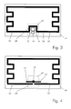
- FIG. 4 differs from Fig. 3 in the way of coupling.
- the antenna conductor 54 forms an open antenna loop. Instead of an inductive coupling, as in the FIGS. 1 to 3 However, a capacitive coupling via an electrical coupling field is present.
- a coupling element 60 consists of two lugs 17 which are connected to the chip 14 and which are opposite to interrupted sections of an antenna conductor 52 of an antenna module 50 and run parallel to them.
- a dashed box 62 which defines the coupling element 60 and represents an area in which by introducing a damping element, an attenuation of the coupling loop 16 and the coupling element 60 occurs.
- FIGS. 5a to 5c show a Detektierplättchen according to Fig. 1 with a damping element 64 in different positions over a field 62.
- the damping element 64 consists of an electrically conductive surface, which is aligned parallel to the support plane 20, 54.
- the damping element 64 is displaceable relative to the field 62 and parallel to the carrier plane 20, 54.
- Fig. 5a shows a low coverage and thus a low attenuation
- Fig. 5b shows a mean coverage and thus a medium attenuation
- Fig. 5c shows a strong cover and thus a strong damping.
- the damping element 64 may be a sticker that can be adhered to the respective marked location. This applies both to detectors removable from a guide or to a carrier holder, as well as to a windshield firmly connected detector plates in the form of a sticker.
- Fig. 6 shows a carrier plane of one of the preceding embodiments of a detection wafer with different position marks 66, 68, 70.
- On the position marks 66, 68, 70 are numbers indicating the degree of reduction in the maximum reading range at a corresponding position of the damping element 64.
- the position marks are determined by measuring the distances in the gradations of the markings and determining the positions of the damping element.
- Fig. 7 shows a support holder 72 for a support plane 20, 54 with a Detektierplättchen as it is conveniently used in a motor vehicle.
- a displaceable damping element 64 On the support holder 72 is a displaceable damping element 64.
- a latching nose 74 On the damping element 64, a latching nose 74 is arranged, which can snap relative to the carrier holder 72 in one of the locking grooves 76 in the carrier holder 72 depending on the position.
- the coupling loop 16 and the coupling element 60 is then automatically covered to the extent necessary and thus achieves the desired damping. Outside the carrier holder 72, the detector plate has the full range.
- Fig. 8 shows an additional card 78 with a damping element 64.
- This additional card 78 together with a carrier plane 20, 54 with a Detektierplättchen in a Carrier holder 72 introduced.
- an area of the head loop 16 or of the coupling element 60 is likewise covered and the desired damping achieved.
Landscapes
- Engineering & Computer Science (AREA)
- Physics & Mathematics (AREA)
- Microelectronics & Electronic Packaging (AREA)
- Computer Hardware Design (AREA)
- Theoretical Computer Science (AREA)
- General Physics & Mathematics (AREA)
- Computer Security & Cryptography (AREA)
- Computer Networks & Wireless Communication (AREA)
- Radar, Positioning & Navigation (AREA)
- Remote Sensing (AREA)
- Power Engineering (AREA)
- Electromagnetism (AREA)
- General Engineering & Computer Science (AREA)
- Details Of Aerials (AREA)
Description
- Die Erfindung betrifft ein Detektierplättchen nach dem Oberbegriff des Anspruchs 1.
- Als Detektierplättchen bezeichnet man einen Datenträger mit einem elektronischen Chip, der berührungslos von einem Lesegerät gelesen und gegebenenfalls auch beschrieben werden kann. Die für den Betrieb des Chips benötigte Energie erhält dieser berührungslos vom Lesegerät. Sowohl die Datenübertragung als auch die Energieübertragung erfolgt durch ein elektromagnetisches Feld.
- Detektierplättchen zur Identifizierung von Personen haben vorzugsweise die Größe einer Checkkarte. Bei Detektierplättchen mit einer Betriebsfrequenz im UHF-Bereich (865 - 868 MHz) und SHF-Bereich (2446 - 2454 MHz) sind dabei Dipolantennen der Abmessungen Lambda Halbe oder wenigstens mechanisch verkürzte, aber elektrisch verlängerte Dipolantennen realisierbar. In dieser Bauform kann eine Reichweite von mehreren Metern erzielt werden. Diese Reichweite ermöglicht auch eine Identifizierung von Personen in einem Kraftfahrzeug und dadurch indirekt auch die Zugangskontrolle des von der identifizierten Person benutzten Kraftfahrzeugs.
- Es hat sich gezeigt, dass die Reichweite zwischen ein und demselben Detektierplättchen und einem Lesegerät abhängig vom Typ des Kraftfahrzeugs sein kann. Dazu wurde herausgefunden, dass diese Erscheinung unter anderem auf einer Dämmungsschicht gegen Wärme und Licht in der Windschutzscheibe beruht, die gleichzeitig eine Dämpfung elektromagnetischer Wellen bewirkt. Zwar befindet sich in jeder mit einer Dämmungsschicht versehenen Windschutzscheibe ein für elektromagnetische Wellen durch lässiges Fenster, dennoch besteht die genannte Abhängigkeit der Lesereichweite vom Typ des Kraftfahrzeugs fort.
- Erwünscht wäre statt dessen eine einheitliche Lesereichweite bei unterschiedlichen Fahrzeugen. Um bei Fahrzeugen mit starker Dämpfung noch ein sicheres Lesen eines im Inneren eines Kraftfahrzeugs befindlichen Detektierplättchens zu ermöglichen, müsste die Empfangsempfindlichkeit des Lesegerätes auf eine starke Dämpfung bemessen und eingestellt werden. Bei Fahrzeugen mit einer sehr geringen Dämpfung würde dann aber eine sehr große Reichweite auftreten, was zu Störungen führen kann. Zum Beispiel könnte bei mehreren mit Zufahrtskontrollen ausgestatteten Fahrspuren nicht nur das der gewählten Fahrspur zugeordnete Lesegerät, sondern auch weitere parallel stehende Lesegeräte aktiviert werden, was aber unerwünscht wäre. Bei Fahrzeugen mit einer sehr geringen Dämpfung müsste dementsprechend die Lesereichweite durch geeignete Maßnahmen verringert werden.
- Aus der
EP 2 009 583 A2 ist ein Kartendatenträger mit einem Detektierplättchen bekannt, das ein Chipmodul und ein Antennenmodul umfasst. Das Chipmodul besteht aus einem Chip und einem mit dem Chip verbundenen Koppelelement. Das Antennenmodul umfasst einen Antennenleiter und das Koppelelement ist mit dem Antennenleiter berührungslos gekoppelt. - Ferner ist aus der
US 2010/0194542 A1 ein Detektierplättchen, insbesondere zur Gebührenerfassung, bekannt, das sich an der Windschutzscheibe eines Kraftfahrzeugs befindet. Dieses Detektierplättchen, das eine Antenne umfasst, soll mittels einer Vorrichtung in einen betriebsfähigen Zustand und einen betriebsunfähigen Zustand geschaltet werden können. Als Vorrichtung dient ein Metallelement, das zur Einstellung des betriebsunfähigen Zustands auf die Antenne gesetzt und zur Einstellung des betriebsfähigen Zustands von der Antenne entfernt wird. - Der Erfindung liegt die Aufgabe zugrunde, ein Detektierplättchen zu schaffen, dessen Lesereichweite unter Berücksichtigung der Dämpfung im Inneren eines Fahrzeugs auf eine einheitliche Reichweite eingestellt werden kann.
- Diese Aufgabe wird bei einem Detektierplättchen nach dem Oberbegriff des Anspruchs 1 durch die Merkmale dieses Anspruchs gelöst.
- Weiterbildungen und vorteilhafte Ausgestaltungen ergeben sich aus den Unteransprüchen.
- Der Realisierung der Erfindung liegen folgende Überlegungen zu Grunde. Eine Steuerung der Empfangsempfindlichkeit des Lesegerätes in Abhängigkeit von Kraftfahrzeugtypen würde eine eindeutige Erkennung des Kraftfahrzeugtyps voraussetzen. Dies wäre in der Praxis jedoch mit einem sehr hohen Aufwand verbunden. Eine Fertigung von Detektierplättchen mit unterschiedlicher Reichweite würde den Herstellungsaufwand vergrößern und damit das Detektierplättchen verteuern. Außerdem müsste bei einem Wechsel des Kraftfahrzeugs das Detektierplättchen der zu identifizierenden Person eventuell durch ein anderes mit anderer Reichweite ersetzt werden. Am günstigsten wäre es daher, bei einheitlichen, baugleichen Detektierplättchen deren Reichweite durch einfache zusätzliche Maßnahmen verändern zu können.
- Bei der Erfindung wird davon ausgegangen, dass alle Detektierplättchen einheitlich aufgebaut und durch optimale Anpassung zwischen einem Chip, einem Koppelelement und einem Antennenleiter für eine maximale Reichweite ausgelegt sind. Gleichzeitig ist die Empfangsempfindlichkeit des Lesegerätes so eingestellt, dass die zur zuverlässigen Identifizierung einer Person erforderliche Reichweite auch dann noch erzielt wird, wenn das Detektierplättchen im Kraftfahrzeug eines Typs mitgeführt wird, dass unter getesteten marktüblichen Kraftfahrzeugen die höchste Dämpfung elektromagnetischer Wellen bewirkt. Damit bei Kraftfahrzeugen mit geringerem Dämpfungsmaß die Reichweite nicht unerwünscht ansteigt, wird das Detektierplättchen künstlich gedämpft und so die Reichweite wieder auf das gewünschte Maß verringert. Zur Dämpfung dient ein Dämpfungselement, das mechanisch in die Nähe eines Koppelelements zwischen dem Chip und dem Antennenleiter gebracht wird. Die Kopplung erfolgt berührungslos über ein Koppelfeld. In dieses Koppelfeld ragt das Dämpfungselement hinein und dämpft ausschließlich das Koppelfeld. Hingegen wird das elektromagnetische Feld des Antennenleiters nicht gedämpft. Dabei kann durch einen unterschiedlichen Abstand oder eine unterschiedliche Abdeckung ein unterschiedliches Dämpfungsmaß erzielt werden.
- Das Koppelelement, der Antennenleiter und das Dämpfungselement sind einheitlich plan ausgerichtet. Eine reproduzierbare Einstellung der Dämpfung in Abhängigkeit eines bestimmten Abstandes zwischen Dämpfungselement und Koppelelement bzw. Antennenleiter oder in Abhängigkeit einer bestimmten Abdeckung des Koppelelements bzw. Antennenleiters durch das Dämpfungselement ist so gewährleistet.
- Durch eine Verschiebung des Dämpfungselements in derselben Dimension, in der auch das Koppelelement und der Antennenleiter ausgeprägt sind, wird eine feinfühlige und lineare Veränderung der Dämpfung in Abhängigkeit der Verschiebung des Dämpfungselements erzielt.
- Das die berührungslose Kopplung herstellende Koppelfeld ist ein magnetisches, induktiv erzeugtes, oder elektrisches, kapazitiv erzeugtes, oder elektromagnetisches Koppelfeld.
- Das Dämpfungselement kann auf der Trägerebene gelagert sein.
- Dadurch wird zwangsläufig eine mechanische Kopplung zwischen dem Dämpfungselement und dem auf der Trägerebene befindlichen Koppelelement und Antennenleiter bewirkt. Die Einstellung des Dämpfungsmaßes und die Handhabung des Detektierplättchens werden so erleichtert.
- Das Dämpfungselement kann auf einem Trägerhalter gelagert sein.
- Zunächst ist die Verwendung eines Trägerhalters in einem Kraftfahrzeug zweckmäßig, da auf diese Weise die richtige Positionierung des Detektierplättchens in Bezug auf ein für elektromagnetische Wellen durchlässiges Fenster in der Windschutzscheibe gewährleistet ist. Die Anordnung des Dämpfungselements auf dem Trägerhalter bewirkt, dass bei Einschieben des auf der Trägerebene angeordneten Detektierplättchens automatisch eine voreingestellte Dämpfung wirksam wird, ohne dass an dem Detektierplättchen selbst oder an dessen Trägerebene irgendwelche mechanische Veränderungen vorgenommen werden müssen.
- Das Dämpfungselement kann auf einer Zusatzkarte angeordnet sein, die in den Trägerhalter einschiebbar ist.
- Dies ermöglicht durch Wahl unterschiedlicher Zusatzkarten eine andere Art der Einstellung der Dämpfung mittels des Trägeralters.
- Auf der Trägerebene und/oder dem Trägerhalter und/oder der Zusatzkarte können Positionsmarken angeordnet sein, die unterschiedlichen Dämpfungsmaßen entsprechen.
- Diese aufgrund von Vorversuchen ermittelten Positionsmarken ermöglichen eine gezielte Einstellung des erforderlichen Dämpfungsmaßes für die gewünschte Lesereichweite des Detektierplättchens durch den Benutzer.
- Das Dämpfungselement und/oder der Trägerhalter können wenigstens eine federbelastete Rastnase aufweisen, die in Dämpfungspositionen in eine der Rastnuten der Trägerebene und/oder der Zusatzkarte einrastet.
- Durch die Rastnase und Rastnuten ist gewährleistet, dass die Position des Dämpfungselements gegenüber der Trägerebene nach einer manuellen Einstellung eingehalten wird nicht durch Lageveränderungen oder Erschütterungen verändert wird.
- Das Detektierplättchen kann als Aufkleber ausgeführt sein, der seine Resonanzfrequenz erst erreicht, wenn er auf die Windschutzscheibe aufgeklebt wird. Im Unterschied zu den zuvor beschriebenen Varianten verbleibt das Detektierplättchen nach der Montage im Kraftfahrzeug. Auf der Rückseite des Detektierplättchens zur Fahrzeuginnenseite hin wird dann an einer Markierung das Dämpfungselement ebenfalls durch Aufkleben angebracht. Mithilfe des aufgeklebten Dämpfungselements können wie zuvor beschrieben verschiedene Dämpfungsstufen durch die Position des aufgeklebten Dämpfungselements an den Markierungslinien eingestellt werden.
- Nachfolgend wird die Erfindung anhand von Ausführungsbeispielen erläutert, die in der Zeichnung dargestellt sind.
- In der Zeichnung zeigen:
- Fig. 1 - 4
- Detektierplättchen mit unterschiedlichen Antennen- und Koppelvarianten,
- Fig. 5a - c
- ein Detektierplättchen mit einem Dämpfungselement in unterschiedlichen Positionen,
- Fig. 6
- eine Trägerebene eines Detektierplättchens mit unterschiedlichen Positionsmarken,
- Fig. 7
- einen Trägerhalter mit einem Dämpfungselement und
- Fig. 8
- eine Zusatzkarte mit einem Dämpfungselement.
- Die in den
Figuren 1 - 4 dargestellten Detektierplättchen umfassen unterschiedliche Antennen- und Koppelvarianten. Das Detektierplättchen nachFig. 1 zeigt ein Chipmodul 10 und ein Antennenmodul 12. Das Chipmodul 10 besteht aus einem Chip 14 und einer mit dem Chip 14 verbundenen Koppelschleife 16. Das Antennenmodul 12 besteht aus einem mit der Koppelschleife 16 induktiv gekoppelten Antennenleiter 18. Das Chipmodul 10 aus dem Chip 14 und der Koppelschleife 16 sowie das Antennenmodul 12 mit dem Antennenleiter 18 befindet sich auf einer Trägerebene 20, die hier eine Kunststofffolie ist. Der Antennenleiter 18 ist ein isolierter Draht, der durch Verlegetechnik mittels Druck und Wärme auf der Trägerebene 20 mechanisch befestigt ist. - Der Antennenleiter 18 ist nach Art einer Schleife in der Form eines Rechteckes strukturiert. An einem dem Chipmodul 10 benachbarten Schenkel 22 des Antennenleiters 18 ist eine Schlaufe 24 ausgebildet, die für eine enge Kopplung der Antennenschleife mit der Koppelschleife 16 des Chipmoduls 10 sorgt. Zwei sich gegenüberliegende, dem Schenkel 22 rechtwinklig anschließende Schenkeln 26, 28 des Antennenleiters 18 sind mäanderförmig gestaltet. Die Mäanderform sorgt für eine elektrische Verlängerung einer mechanisch verkürzten Antenne. An einem dem Schenkel 22 und dem Chipmodul 10 gegenüberliegenden Schenkel 30 der Antennenschleife sind Endbereiche 32, 34 des Antennenleiters 18 überlappend parallel mit geringem Abstand zueinander positioniert, aber nicht elektrisch verbunden sind.
- Das in
Fig. 2 dargestellte Detektierplättchen unterscheidet sich von dem inFig. 1 gezeigten durch die Ausgestaltung des Antennenmoduls 36. Das Antennenmodul 36 besteht aus einem Antennenleiter 38, der durch Verlegetechnik auf einer aus einer Kunststofffolie bestehenden Trägerebene 20 angeordnet und befestigt ist. Der Antennenleiter 38 umfasst mehrere Windungen, deren Enden 42, 44 zu einem Chip 46 für den HF-Bereich geführt und mit Anschlüssen des Chips 46 verschweißt sind. - Die Windungen der durch den Antennenleiter 38 gebildeten Schleife haben ebenfalls eine Rechteckstruktur. An der dem Chip 46 gegenüberliegenden Seite verlaufen Windungsbereiche als Schlaufe 48. Analog zu
Fig. 1 ist das Chipmodul 10 so auf der Trägerebene 20 positioniert und befestigt, dass die Koppelschleife 16 durch die Schlaufe 48 umschlossen wird. Die mehreren Windungen des Antennenleiters 38 verhalten sich durch kapazitiven Schluss für das Chipmodul 10 im UHF-Bereich wie eine Einwindungsantenne analog zu der Darstellung nachFig. 1 . - Bei der Darstellung nach
Fig. 3 besteht ein Antennenmodul 50 aus einer in Ätztechnik hergestellten Leiterbahn als Antennenleiter 52 auf einer aus einer Leiterplatine bestehenden Trägerebene 54. Der Antennenleiter 52 bildet eine geschlossene Antennenschleife. An einem dem Chipmodul 10 benachbarten Schenkel 56 des Antennenleiters 52 ist eine Schlaufe 58 ausgebildet, die für eine enge Kopplung der Antennenschleife mit der Koppelschleife 16 des Chipmoduls 10 sorgt. Die Kopplung erfolgt induktiv über ein magnetisches Koppelfeld. - Die Darstellung nach
Fig. 4 unterscheidet sich vonFig. 3 in der Art der Kopplung. Der Antennenleiter 54 bildet eine offene Antennenschleife. Statt einer induktiven Kopplung, wie bei denFiguren 1 bis 3 , ist jedoch eine kapazitive Kopplung über ein elektrisches Koppelfeld vorhanden. Ein Koppelelement 60 besteht aus zwei mit dem Chip 14 verbundenen Fähnchen 17, die unterbrochenen Abschnitten eines Antennenleiter 52 eines Antennenmoduls 50 gegenüberstehen und parallel zu diesen verlaufen. - Allen Darstellungen nach den
Figuren 1 bis 4 gemeinsam ist ein gestrichelt gezeichnetes Feld 62, das das Koppelelement 60 umgrenzt und einen Bereich darstellt, in dem durch Einführen eines Dämpfungselements eine Dämpfung der Koppelschleife 16 bzw. des Koppelelements 60 eintritt. - Die
Figuren 5a bis 5c zeigen ein Detektierplättchen gemäßFig. 1 mit einem Dämpfungselement 64 in unterschiedlichen Positionen über einem Feld 62. Das Dämpfungselement 64 besteht aus einer elektrisch leitfähigen Fläche, die parallel zur Trägerebene 20, 54 ausgerichtet ist. Das Dämpfungselement 64 ist relativ zum Feld 62 und parallel zur Trägerebene 20, 54 verschiebbar. Durch eine unterschiedlich breite Abdeckung des Feldes 62 mit der darin befindlichen Koppelschleife 16 bzw. dem darin befindlichen Koppelelement 60 wird die Anpassung zwischen dem Chip 14 und dem Antennenleiter 18, 38, 52 verändert. Diese Anpassung verschlechtert sich mit zunehmender Abdeckung des Feldes 62, wodurch das Detektierplättchen gedämpft wird und die Leserreichweite vermindert wird. - In den
Figuren 5a bis 5c sind drei verschiedene Dämpfungspositionen dargestellt.Fig. 5a zeigt eine geringe Abdeckung und damit eine geringe Dämpfung,Fig. 5b zeigt eine mittlere Abdeckung und damit eine mittlere Dämpfung undFig. 5c zeigt eine starke Abdeckung und damit eine starke Dämpfung. Ohne Dämpfungselement 64 besteht keine Dämpfung. Das Dämpfungselement 64 kann dabei ein Aufkleber sein, der an der jeweils markierten Stelle aufgeklebt werden kann. Dies trifft sowohl für aus einer Führung oder einem Trägerhalter entfernbare Detektierplättchen zu, wie auch mit einer Windschutzscheibe fest verbundenen Detektierplättchen in Form eines Aufklebers. -
Fig. 6 zeigt eine Trägerebene einer der vorangehenden Ausführungen eines Detektierplättchens mit unterschiedlichen Positionsmarken 66, 68, 70. An den Positionsmarken 66, 68, 70 befinden sich Zahlenangaben, die das Maß der Verringerung der maximalen Lesereichweite bei entsprechender Stellung des Dämpfungselements 64 angeben. In der Praxis werden die Positionsmarken dadurch festgelegt, dass Reichweitenmessungen in den Abstufungen der Markierungen vorgenommen werden und die Stellungen des Dämpfungselements ermittelt werden. -
Fig. 7 zeigt einen Trägerhalter 72 für eine Trägerebene 20, 54 mit einem Detektierplättchen, wie er zweckmäßig in einem Kraftfahrzeug eingesetzt wird. Auf dem Trägerhalter 72 befindet sich ein verschiebbares Dämpfungselement 64. An dem Dämpfungselement 64 ist eine Rastnase 74 angeordnet, die je nach Position relativ zum Trägerhalter 72 in eine der Rastnuten 76 im Trägerhalter 72 ein rasten kann. Bei Einführen einer Trägerebene 20, 54 mit einem Detektierplättchen in einen Trägerhalter 72 wird die Koppelschleife 16 bzw. das Koppelelement 60 dann automatisch im erforderlichen Maße abgedeckt und damit die gewünschte Dämpfung erzielt. Außerhalb des Trägerhalters 72 hat das Detektierplättchen die volle Reichweite. -
Fig. 8 zeigt eine Zusatzkarte 78 mit einem Dämpfungselement 64. Diese Zusatzkarte 78 wird zusammen mit einer Trägerebene 20, 54 mit einem Detektierplättchen in einen Trägerhalter 72 eingeführt. Dabei wird dann ebenfalls ein Bereich der Kopfschleife 16 bzw. des Koppelelements 60 abgedeckt und die gewünschte Dämpfung erzielt. Es sind drei Zusatzkarten 78 verfügbar, bei der das Dämpfungselement 64 jeweils an unterschiedlichen Positionen angeordnet ist. Entsprechende Zahlenangaben zeigen das Maß der Reichweitenverminderung bei einer vorgegebenen Position des Dämpfungselements 64 an.
Claims (9)
- Detektierplättchen, umfassend ein Chipmodul (10) aus einem Chip (14) und einem mit dem Chip (14) verbundenen Koppelelement (16, 60) und umfassend ein Antennenmodul (12, 36, 50) aus einem Antennenleiter (18, 38, 52), wobei das Koppelelement (16, 60) und der Antennenleiter (18, 38, 52) berührungslos gekoppelt und auf einer Trägerebene (20, 54) angeordnet sind und umfassend ein verstellbares Dämpfungselement (64), welches als elektrisch leitfähige Fläche parallel zur Trägerebene (20, 54) ausgerichtet ist und das Koppelelement (16, 60) in Dämpfungspositionen teilweise abdeckt und somit das die berührungslose Kopplung herstellende Koppelfeld (62) dämpft, dadurch gekennzeichnet, dass das Dämpfungselement (64) parallel zur Trägerebene (20, 54) in derselben Dimension, in der auch das Koppelelement (16, 60) und der Antennenleiter (18, 38, 52) angeordnet sind, verschiebbar ist, und durch eine Verschiebung des Dämpfungselements (64) eine kontrollierte und mehrstufige Veränderung der Dämpfung möglich ist.
- Detektierplättchen nach Anspruch 1, dadurch gekennzeichnet, dass das die berührungslose Kopplung herstellende Koppelfeld (62) ein magnetisches, induktiv erzeugtes, oder elektrisches, kapazitiv erzeugtes, oder elektromagnetisches Koppelfeld (62) ist.
- Detektierplättchen nach Anspruch 1 oder 2, dadurch gekennzeichnet, dass das Dämpfungselement (64) auf der Trägerebene (20, 54) gelagert ist.
- Detektierplättchen nach Anspruch 1 oder 2, dadurch gekennzeichnet, dass das Dämpfungselement (64) auf einem Trägerhalter (72) gelagert ist.
- Detektierplättchen nach Anspruch 1 oder 2, dadurch gekennzeichnet, dass das Dämpfungselement (64) auf einer Zusatzkarte (78) angeordnet ist, die in einen Trägerhalter (72) einschiebbar ist.
- Detektierplättchen nach einem der Ansprüche 3 bis 5, dadurch gekennzeichnet, dass auf der Trägerebene (20, 54) und/oder dem Trägerhalter (72) und/oder der Zusatzkarte (78) Positionsmarken (66, 68, 70) angeordnet sind, die unterschiedlichen Dämpfungsmaßen entsprechen.
- Detektierplättchen nach Anspruch 6, dadurch gekennzeichnet, dass das Dämpfungselement (64) an einer der Positionsmarken (66, 68, 70) angeklebt ist.
- Detektierplättchen nach einem der Ansprüche 3 bis 6, dadurch gekennzeichnet, dass das Dämpfungselement (64) und/oder der Trägerhalter (72) und/oder die Zusatzkarte (78) wenigstens eine federbelastete Rastnase (74) aufweisen, die in Dämpfungspositionen in eine der Rastnuten (76) der Trägerebene (20, 54) einrastet.
- Detektierplättchen nach einem der Ansprüche 1 bis 8, dadurch gekennzeichnet, dass das Detektierplättchen fest mit einer Windschutzscheibe verbunden oder in einem Trägerhalter (72) angeordnet ist.
Applications Claiming Priority (1)
| Application Number | Priority Date | Filing Date | Title |
|---|---|---|---|
| DE202011002173U DE202011002173U1 (de) | 2011-02-01 | 2011-02-01 | Detektierplättchen |
Publications (2)
| Publication Number | Publication Date |
|---|---|
| EP2482469A1 EP2482469A1 (de) | 2012-08-01 |
| EP2482469B1 true EP2482469B1 (de) | 2016-06-29 |
Family
ID=44312767
Family Applications (1)
| Application Number | Title | Priority Date | Filing Date |
|---|---|---|---|
| EP12000301.7A Active EP2482469B1 (de) | 2011-02-01 | 2012-01-19 | Detektierplättchen mit anpassbarer Sende- und Empfangsreichweite durch Positionieren eines verstellbaren Dämpfungselements. |
Country Status (3)
| Country | Link |
|---|---|
| US (1) | US8763915B2 (de) |
| EP (1) | EP2482469B1 (de) |
| DE (1) | DE202011002173U1 (de) |
Families Citing this family (3)
| Publication number | Priority date | Publication date | Assignee | Title |
|---|---|---|---|---|
| JP6485555B2 (ja) * | 2015-12-02 | 2019-03-20 | 株式会社村田製作所 | 水分検出用rfidタグ付き衛生用品 |
| US10373045B2 (en) | 2016-12-01 | 2019-08-06 | Avery Dennison Retail Information Services, Llc | Coupling of RFID straps to antennae using a combination of magnetic and electric fields |
| JP2020005170A (ja) * | 2018-06-29 | 2020-01-09 | 共同印刷株式会社 | 無線装置及び通信方法 |
Family Cites Families (44)
| Publication number | Priority date | Publication date | Assignee | Title |
|---|---|---|---|---|
| US6466131B1 (en) * | 1996-07-30 | 2002-10-15 | Micron Technology, Inc. | Radio frequency data communications device with adjustable receiver sensitivity and method |
| US6208235B1 (en) * | 1997-03-24 | 2001-03-27 | Checkpoint Systems, Inc. | Apparatus for magnetically decoupling an RFID tag |
| DE19731035B4 (de) | 1997-07-18 | 2004-09-02 | Anatoli Stobbe | Verfahren zur Datenübertragung zwischen einem Schreib-Lesegerät und einem Transponder |
| CN1179295C (zh) * | 1997-11-14 | 2004-12-08 | 凸版印刷株式会社 | 复合ic模块及复合ic卡 |
| US6121544A (en) * | 1998-01-15 | 2000-09-19 | Petsinger; Julie Ann | Electromagnetic shield to prevent surreptitious access to contactless smartcards |
| US6127938A (en) * | 1999-02-12 | 2000-10-03 | Privacy Shield L.L.C. | Adjustable shield for vehicle mounted toll collection identifier |
| EP1030266B1 (de) * | 1999-02-19 | 2009-05-06 | Nippon Telegraph and Telephone Corporation | Kontaktlose Chipkarte und System hierfür |
| JP2001167173A (ja) * | 1999-12-08 | 2001-06-22 | Sony Corp | 情報流通システム及び情報の管理方法 |
| JP2001167242A (ja) * | 1999-12-10 | 2001-06-22 | Sony Corp | エンボス加工可能なicカード、その製造方法及びその情報読取確認システム |
| US7106196B2 (en) | 2001-07-12 | 2006-09-12 | Intermec Ip Corp | Method and apparatus for configuring the read-range of an RFID label or tag |
| US6830193B2 (en) * | 2001-11-29 | 2004-12-14 | Matsushita Electric Industrial Co., Ltd. | Non-contact IC card |
| JP2004227046A (ja) * | 2003-01-20 | 2004-08-12 | Hitachi Ltd | 携帯情報機器 |
| ATE530998T1 (de) * | 2003-07-07 | 2011-11-15 | Avery Dennison Corp | Rfid-einrichtung mit änderbaren charakteristika |
| JP2005033413A (ja) | 2003-07-10 | 2005-02-03 | Matsushita Electric Ind Co Ltd | ループアンテナ及び非接触icカード読取/書込装置 |
| DE102004041397B3 (de) | 2004-08-26 | 2005-12-08 | Siemens Ag | Aufbewahrungsmittel für kontaktlose Chip-Karten zum Schutz vor unberechtigtem Auslesen |
| US20060044769A1 (en) * | 2004-09-01 | 2006-03-02 | Forster Ian J | RFID device with magnetic coupling |
| US7158033B2 (en) * | 2004-09-01 | 2007-01-02 | Avery Dennison Corporation | RFID device with combined reactive coupler |
| US7253734B2 (en) | 2004-09-22 | 2007-08-07 | International Business Machines Corporation | System and method for altering or disabling RFID tags |
| JP4289338B2 (ja) * | 2005-09-29 | 2009-07-01 | 沖電気工業株式会社 | Rfidタグ通信システム、rfidタグ及び誘導アンテナ装置 |
| JP4075919B2 (ja) * | 2005-09-29 | 2008-04-16 | オムロン株式会社 | アンテナユニットおよび非接触icタグ |
| US7777626B2 (en) * | 2005-10-13 | 2010-08-17 | BAE Systems Information and Electronic Systems, Integration, Inc. | RFID tag incorporating at least two integrated circuits |
| US7808384B2 (en) * | 2006-07-14 | 2010-10-05 | Eyes Open Corporation | Information carrier arrangement, washable textile goods and electronic ear tag for living beings |
| US7731094B2 (en) * | 2006-07-17 | 2010-06-08 | Mastercard International, Inc. | Method and apparatus for personalizing contactless card with switch |
| US7578431B2 (en) * | 2006-09-06 | 2009-08-25 | Mastercard International, Inc. | Proximity payment card with printed indication of switch location |
| US8322624B2 (en) * | 2007-04-10 | 2012-12-04 | Feinics Amatech Teoranta | Smart card with switchable matching antenna |
| US7791453B2 (en) | 2006-11-21 | 2010-09-07 | International Business Machines Corporation | System and method for varying response amplitude of radio transponders |
| US8193911B2 (en) * | 2006-12-20 | 2012-06-05 | International Business Machines Corporation | Controlling radio frequency identification tag signal range |
| DE102006062308A1 (de) | 2006-12-27 | 2008-07-17 | ASTRA Gesellschaft für Asset Management mbH & Co. KG | Passives Detektierplättchen |
| DE102007017864A1 (de) * | 2007-04-13 | 2008-10-16 | ASTRA Gesellschaft für Asset Management mbH & Co. KG | Verfahren und Vorrichtung zum Schutz gegen Fernauslesen von Warenkennzeichnungsdaten |
| US7817045B2 (en) | 2007-05-30 | 2010-10-19 | Onderko John C | Handling system for exception RFID labels |
| DE102007029083B4 (de) * | 2007-06-21 | 2019-05-16 | ASTRA Gesellschaft für Asset Management mbH & Co. KG | Kartendatenträger mit Detektierplättchen |
| ATE520167T1 (de) * | 2007-10-03 | 2011-08-15 | Assa Abloy Ab | Kopplungsvorrichtung für einen transponder und chipkarte mit derartiger vorrichtung |
| EP2073152A1 (de) * | 2007-12-17 | 2009-06-24 | Gemplus | Warnsystem zum Signalisieren der Präsenz einer Funkkommunikation und Herstellungsverfahren |
| FR2928475B1 (fr) * | 2008-03-05 | 2010-05-07 | Commissariat Energie Atomique | Dispositif de communication sans contact. |
| US8228199B2 (en) * | 2008-03-27 | 2012-07-24 | Amtech Systems, LLC | RFID tag with integrated disabling and method of use |
| US8289165B2 (en) * | 2008-06-11 | 2012-10-16 | Avery Dennison Corporation | RFID device with conductive loop shield |
| EP2307909B1 (de) | 2008-07-30 | 2013-01-16 | Nxp B.V. | System zum lesen von transponderübermittelten informationen |
| GB0902952D0 (en) | 2009-02-23 | 2009-04-08 | Qinetiq Ltd | Radiation attenuation |
| US8474726B2 (en) * | 2010-08-12 | 2013-07-02 | Feinics Amatech Teoranta | RFID antenna modules and increasing coupling |
| US8717146B2 (en) * | 2010-06-30 | 2014-05-06 | General Electric Company | Methods and systems for integrated interrogation of RFID sensors |
| FR2963139B1 (fr) * | 2010-07-20 | 2012-09-14 | Oberthur Technologies | Dispositif a microcircuit comprenant des moyens d'amplification du gain d'une antenne |
| US8490880B2 (en) * | 2010-12-28 | 2013-07-23 | Mastercard International Incorporated | Proximity payment device with active switch |
| MX337373B (es) * | 2011-05-06 | 2016-02-29 | Neology Inc | Etiqueta interruptor de rfid. |
| US8763914B2 (en) * | 2012-01-17 | 2014-07-01 | On Track Innovations Ltd. | Decoupled contactless bi-directional systems and methods |
-
2011
- 2011-02-01 DE DE202011002173U patent/DE202011002173U1/de not_active Expired - Lifetime
-
2012
- 2012-01-19 EP EP12000301.7A patent/EP2482469B1/de active Active
- 2012-02-01 US US13/363,677 patent/US8763915B2/en active Active
Also Published As
| Publication number | Publication date |
|---|---|
| DE202011002173U1 (de) | 2011-06-01 |
| US20130026237A1 (en) | 2013-01-31 |
| US8763915B2 (en) | 2014-07-01 |
| EP2482469A1 (de) | 2012-08-01 |
Similar Documents
| Publication | Publication Date | Title |
|---|---|---|
| DE69635792T2 (de) | Antenne für Lese-/Schreibgerät | |
| WO2007147593A1 (de) | Transponder mit elektronischem speicherchip und magnetischer ringantenne | |
| DE102011056323A1 (de) | Booster-Antennenstruktur für eine Chipkarte | |
| DE102006057369A1 (de) | RFID-Etikett, sowie dessen Verwendung und ein damit gekennzeichnetes Objekt | |
| EP0826190A1 (de) | Kontaktlose chipkarte | |
| EP2600276B1 (de) | Vorrichtung mit einem RFID-Reader | |
| DE60014708T2 (de) | Antenne für radiofrequenzen für ein objektabfragegerät mit einer radiofrequenzantenne und ein damit verbundener elektrischer schaltkreis | |
| EP1435067B8 (de) | Einrichtung zum abschirmen eines transponders, verfahren zum herstellen einer entsprechenden abschirmung sowie transponder mit abschirmung | |
| EP1939793B1 (de) | Passives RF-Detektierplättchen | |
| DE102006055744A1 (de) | Antenne für einen rückstreubasierten RFID-Transponder | |
| EP2482469A1 (de) | Detektierplättchen mit anpassbarer Sende- und Empfangsreichweite durch Positionieren eines verstellbaren Dämpfungselements. | |
| DE102006007423A1 (de) | Vorrichtung und Verfahren zum Testen der Lesezuverlässigkeit von Smart Labels | |
| DE102008049371A1 (de) | Einrichtung mit einem RFID-Transponder in einem elektrisch leitfähigen Gegenstand und Herstellungsverfahren hierfür | |
| EP2586098B1 (de) | Detektierplättchen | |
| EP3070636B1 (de) | Lesefeldindikator zur prüfung des lesefeldes eines rfid-lesegerätes | |
| DE102007058277A1 (de) | Fahrzeuginsassen-Schutzvorrichtung | |
| WO2007131879A1 (de) | Testvorrichtung mit hf-/uhf-dualbandantenne zum testen von rfid-transpondern in einem fertigungsgerät | |
| DE102012101443A1 (de) | Planare Antennenanordnung | |
| DE212009000026U1 (de) | Verbindungssensor zur Identifikation einer Anschlussstelle in einer Schalttafel | |
| DE102013112599A1 (de) | RFID-Antennenanordnung mit wenigstens einer RFID-Antenne sowie Verfahren zur Bestimmung eines Abstandes von wenigstens zwei Leiterschleifen einer RFID-Antenne einer RFID-Antennenanordnung | |
| EP3455640B1 (de) | Antennenmesskammer | |
| EP1843281A1 (de) | Datenträger-/Sendevorrichtung und Verfahren zur Herstellung einer Datenträger-/Sendevorrichtung | |
| DE102015102288B4 (de) | Chipkarten-Leseanordnung | |
| EP2036006B1 (de) | Chipkarte und verfahren zur herstellung einer chipkarte | |
| DE102010052399B4 (de) | Portabler Datenträger mit Kontaktelement |
Legal Events
| Date | Code | Title | Description |
|---|---|---|---|
| PUAI | Public reference made under article 153(3) epc to a published international application that has entered the european phase |
Free format text: ORIGINAL CODE: 0009012 |
|
| AK | Designated contracting states |
Kind code of ref document: A1 Designated state(s): AL AT BE BG CH CY CZ DE DK EE ES FI FR GB GR HR HU IE IS IT LI LT LU LV MC MK MT NL NO PL PT RO RS SE SI SK SM TR |
|
| AX | Request for extension of the european patent |
Extension state: BA ME |
|
| 17P | Request for examination filed |
Effective date: 20121130 |
|
| 17Q | First examination report despatched |
Effective date: 20150515 |
|
| REG | Reference to a national code |
Ref country code: DE Ref legal event code: R079 Ref document number: 502012007480 Country of ref document: DE Free format text: PREVIOUS MAIN CLASS: H04B0005000000 Ipc: H01Q0007000000 |
|
| GRAP | Despatch of communication of intention to grant a patent |
Free format text: ORIGINAL CODE: EPIDOSNIGR1 |
|
| INTG | Intention to grant announced |
Effective date: 20160415 |
|
| RIC1 | Information provided on ipc code assigned before grant |
Ipc: G06K 19/077 20060101ALI20160401BHEP Ipc: H01Q 23/00 20060101ALI20160401BHEP Ipc: H01Q 1/32 20060101ALI20160401BHEP Ipc: H01Q 1/22 20060101ALI20160401BHEP Ipc: G06K 19/073 20060101ALI20160401BHEP Ipc: H01Q 7/00 20060101AFI20160401BHEP |
|
| GRAS | Grant fee paid |
Free format text: ORIGINAL CODE: EPIDOSNIGR3 |
|
| GRAA | (expected) grant |
Free format text: ORIGINAL CODE: 0009210 |
|
| AK | Designated contracting states |
Kind code of ref document: B1 Designated state(s): AL AT BE BG CH CY CZ DE DK EE ES FI FR GB GR HR HU IE IS IT LI LT LU LV MC MK MT NL NO PL PT RO RS SE SI SK SM TR |
|
| REG | Reference to a national code |
Ref country code: GB Ref legal event code: FG4D Free format text: NOT ENGLISH |
|
| REG | Reference to a national code |
Ref country code: CH Ref legal event code: EP |
|
| REG | Reference to a national code |
Ref country code: AT Ref legal event code: REF Ref document number: 809752 Country of ref document: AT Kind code of ref document: T Effective date: 20160715 |
|
| REG | Reference to a national code |
Ref country code: IE Ref legal event code: FG4D Free format text: LANGUAGE OF EP DOCUMENT: GERMAN |
|
| REG | Reference to a national code |
Ref country code: DE Ref legal event code: R096 Ref document number: 502012007480 Country of ref document: DE |
|
| REG | Reference to a national code |
Ref country code: LT Ref legal event code: MG4D |
|
| PG25 | Lapsed in a contracting state [announced via postgrant information from national office to epo] |
Ref country code: FI Free format text: LAPSE BECAUSE OF FAILURE TO SUBMIT A TRANSLATION OF THE DESCRIPTION OR TO PAY THE FEE WITHIN THE PRESCRIBED TIME-LIMIT Effective date: 20160629 Ref country code: LT Free format text: LAPSE BECAUSE OF FAILURE TO SUBMIT A TRANSLATION OF THE DESCRIPTION OR TO PAY THE FEE WITHIN THE PRESCRIBED TIME-LIMIT Effective date: 20160629 Ref country code: NO Free format text: LAPSE BECAUSE OF FAILURE TO SUBMIT A TRANSLATION OF THE DESCRIPTION OR TO PAY THE FEE WITHIN THE PRESCRIBED TIME-LIMIT Effective date: 20160929 |
|
| REG | Reference to a national code |
Ref country code: NL Ref legal event code: MP Effective date: 20160629 |
|
| PG25 | Lapsed in a contracting state [announced via postgrant information from national office to epo] |
Ref country code: HR Free format text: LAPSE BECAUSE OF FAILURE TO SUBMIT A TRANSLATION OF THE DESCRIPTION OR TO PAY THE FEE WITHIN THE PRESCRIBED TIME-LIMIT Effective date: 20160629 Ref country code: LV Free format text: LAPSE BECAUSE OF FAILURE TO SUBMIT A TRANSLATION OF THE DESCRIPTION OR TO PAY THE FEE WITHIN THE PRESCRIBED TIME-LIMIT Effective date: 20160629 Ref country code: NL Free format text: LAPSE BECAUSE OF FAILURE TO SUBMIT A TRANSLATION OF THE DESCRIPTION OR TO PAY THE FEE WITHIN THE PRESCRIBED TIME-LIMIT Effective date: 20160629 Ref country code: RS Free format text: LAPSE BECAUSE OF FAILURE TO SUBMIT A TRANSLATION OF THE DESCRIPTION OR TO PAY THE FEE WITHIN THE PRESCRIBED TIME-LIMIT Effective date: 20160629 Ref country code: SE Free format text: LAPSE BECAUSE OF FAILURE TO SUBMIT A TRANSLATION OF THE DESCRIPTION OR TO PAY THE FEE WITHIN THE PRESCRIBED TIME-LIMIT Effective date: 20160629 Ref country code: GR Free format text: LAPSE BECAUSE OF FAILURE TO SUBMIT A TRANSLATION OF THE DESCRIPTION OR TO PAY THE FEE WITHIN THE PRESCRIBED TIME-LIMIT Effective date: 20160930 |
|
| REG | Reference to a national code |
Ref country code: FR Ref legal event code: PLFP Year of fee payment: 6 |
|
| PG25 | Lapsed in a contracting state [announced via postgrant information from national office to epo] |
Ref country code: CZ Free format text: LAPSE BECAUSE OF FAILURE TO SUBMIT A TRANSLATION OF THE DESCRIPTION OR TO PAY THE FEE WITHIN THE PRESCRIBED TIME-LIMIT Effective date: 20160629 Ref country code: IT Free format text: LAPSE BECAUSE OF FAILURE TO SUBMIT A TRANSLATION OF THE DESCRIPTION OR TO PAY THE FEE WITHIN THE PRESCRIBED TIME-LIMIT Effective date: 20160629 Ref country code: IS Free format text: LAPSE BECAUSE OF FAILURE TO SUBMIT A TRANSLATION OF THE DESCRIPTION OR TO PAY THE FEE WITHIN THE PRESCRIBED TIME-LIMIT Effective date: 20161029 Ref country code: RO Free format text: LAPSE BECAUSE OF FAILURE TO SUBMIT A TRANSLATION OF THE DESCRIPTION OR TO PAY THE FEE WITHIN THE PRESCRIBED TIME-LIMIT Effective date: 20160629 Ref country code: SK Free format text: LAPSE BECAUSE OF FAILURE TO SUBMIT A TRANSLATION OF THE DESCRIPTION OR TO PAY THE FEE WITHIN THE PRESCRIBED TIME-LIMIT Effective date: 20160629 Ref country code: EE Free format text: LAPSE BECAUSE OF FAILURE TO SUBMIT A TRANSLATION OF THE DESCRIPTION OR TO PAY THE FEE WITHIN THE PRESCRIBED TIME-LIMIT Effective date: 20160629 |
|
| PG25 | Lapsed in a contracting state [announced via postgrant information from national office to epo] |
Ref country code: PT Free format text: LAPSE BECAUSE OF FAILURE TO SUBMIT A TRANSLATION OF THE DESCRIPTION OR TO PAY THE FEE WITHIN THE PRESCRIBED TIME-LIMIT Effective date: 20161031 Ref country code: ES Free format text: LAPSE BECAUSE OF FAILURE TO SUBMIT A TRANSLATION OF THE DESCRIPTION OR TO PAY THE FEE WITHIN THE PRESCRIBED TIME-LIMIT Effective date: 20160629 Ref country code: PL Free format text: LAPSE BECAUSE OF FAILURE TO SUBMIT A TRANSLATION OF THE DESCRIPTION OR TO PAY THE FEE WITHIN THE PRESCRIBED TIME-LIMIT Effective date: 20160629 Ref country code: SM Free format text: LAPSE BECAUSE OF FAILURE TO SUBMIT A TRANSLATION OF THE DESCRIPTION OR TO PAY THE FEE WITHIN THE PRESCRIBED TIME-LIMIT Effective date: 20160629 |
|
| REG | Reference to a national code |
Ref country code: DE Ref legal event code: R097 Ref document number: 502012007480 Country of ref document: DE |
|
| PLBE | No opposition filed within time limit |
Free format text: ORIGINAL CODE: 0009261 |
|
| STAA | Information on the status of an ep patent application or granted ep patent |
Free format text: STATUS: NO OPPOSITION FILED WITHIN TIME LIMIT |
|
| PG25 | Lapsed in a contracting state [announced via postgrant information from national office to epo] |
Ref country code: DK Free format text: LAPSE BECAUSE OF FAILURE TO SUBMIT A TRANSLATION OF THE DESCRIPTION OR TO PAY THE FEE WITHIN THE PRESCRIBED TIME-LIMIT Effective date: 20160629 Ref country code: BE Free format text: LAPSE BECAUSE OF NON-PAYMENT OF DUE FEES Effective date: 20170131 |
|
| 26N | No opposition filed |
Effective date: 20170330 |
|
| PG25 | Lapsed in a contracting state [announced via postgrant information from national office to epo] |
Ref country code: BG Free format text: LAPSE BECAUSE OF FAILURE TO SUBMIT A TRANSLATION OF THE DESCRIPTION OR TO PAY THE FEE WITHIN THE PRESCRIBED TIME-LIMIT Effective date: 20160929 Ref country code: SI Free format text: LAPSE BECAUSE OF FAILURE TO SUBMIT A TRANSLATION OF THE DESCRIPTION OR TO PAY THE FEE WITHIN THE PRESCRIBED TIME-LIMIT Effective date: 20160629 |
|
| REG | Reference to a national code |
Ref country code: CH Ref legal event code: PL |
|
| PG25 | Lapsed in a contracting state [announced via postgrant information from national office to epo] |
Ref country code: MC Free format text: LAPSE BECAUSE OF FAILURE TO SUBMIT A TRANSLATION OF THE DESCRIPTION OR TO PAY THE FEE WITHIN THE PRESCRIBED TIME-LIMIT Effective date: 20160629 |
|
| PG25 | Lapsed in a contracting state [announced via postgrant information from national office to epo] |
Ref country code: LI Free format text: LAPSE BECAUSE OF NON-PAYMENT OF DUE FEES Effective date: 20170131 Ref country code: CH Free format text: LAPSE BECAUSE OF NON-PAYMENT OF DUE FEES Effective date: 20170131 |
|
| REG | Reference to a national code |
Ref country code: IE Ref legal event code: MM4A |
|
| PG25 | Lapsed in a contracting state [announced via postgrant information from national office to epo] |
Ref country code: LU Free format text: LAPSE BECAUSE OF NON-PAYMENT OF DUE FEES Effective date: 20170119 |
|
| REG | Reference to a national code |
Ref country code: FR Ref legal event code: PLFP Year of fee payment: 7 |
|
| REG | Reference to a national code |
Ref country code: BE Ref legal event code: MM Effective date: 20170131 |
|
| PG25 | Lapsed in a contracting state [announced via postgrant information from national office to epo] |
Ref country code: IE Free format text: LAPSE BECAUSE OF NON-PAYMENT OF DUE FEES Effective date: 20170119 |
|
| REG | Reference to a national code |
Ref country code: AT Ref legal event code: MM01 Ref document number: 809752 Country of ref document: AT Kind code of ref document: T Effective date: 20170119 |
|
| PG25 | Lapsed in a contracting state [announced via postgrant information from national office to epo] |
Ref country code: AT Free format text: LAPSE BECAUSE OF NON-PAYMENT OF DUE FEES Effective date: 20170119 |
|
| PG25 | Lapsed in a contracting state [announced via postgrant information from national office to epo] |
Ref country code: MT Free format text: LAPSE BECAUSE OF FAILURE TO SUBMIT A TRANSLATION OF THE DESCRIPTION OR TO PAY THE FEE WITHIN THE PRESCRIBED TIME-LIMIT Effective date: 20160629 |
|
| PG25 | Lapsed in a contracting state [announced via postgrant information from national office to epo] |
Ref country code: AL Free format text: LAPSE BECAUSE OF FAILURE TO SUBMIT A TRANSLATION OF THE DESCRIPTION OR TO PAY THE FEE WITHIN THE PRESCRIBED TIME-LIMIT Effective date: 20160629 |
|
| PG25 | Lapsed in a contracting state [announced via postgrant information from national office to epo] |
Ref country code: HU Free format text: LAPSE BECAUSE OF FAILURE TO SUBMIT A TRANSLATION OF THE DESCRIPTION OR TO PAY THE FEE WITHIN THE PRESCRIBED TIME-LIMIT; INVALID AB INITIO Effective date: 20120119 |
|
| PG25 | Lapsed in a contracting state [announced via postgrant information from national office to epo] |
Ref country code: CY Free format text: LAPSE BECAUSE OF NON-PAYMENT OF DUE FEES Effective date: 20160629 |
|
| PG25 | Lapsed in a contracting state [announced via postgrant information from national office to epo] |
Ref country code: MK Free format text: LAPSE BECAUSE OF FAILURE TO SUBMIT A TRANSLATION OF THE DESCRIPTION OR TO PAY THE FEE WITHIN THE PRESCRIBED TIME-LIMIT Effective date: 20160629 |
|
| PG25 | Lapsed in a contracting state [announced via postgrant information from national office to epo] |
Ref country code: TR Free format text: LAPSE BECAUSE OF FAILURE TO SUBMIT A TRANSLATION OF THE DESCRIPTION OR TO PAY THE FEE WITHIN THE PRESCRIBED TIME-LIMIT Effective date: 20160629 |
|
| P01 | Opt-out of the competence of the unified patent court (upc) registered |
Effective date: 20230530 |
|
| PGFP | Annual fee paid to national office [announced via postgrant information from national office to epo] |
Ref country code: GB Payment date: 20260122 Year of fee payment: 15 |
|
| PGFP | Annual fee paid to national office [announced via postgrant information from national office to epo] |
Ref country code: DE Payment date: 20260114 Year of fee payment: 15 |
|
| PGFP | Annual fee paid to national office [announced via postgrant information from national office to epo] |
Ref country code: FR Payment date: 20260128 Year of fee payment: 15 |