EP2482020A2 - Heat exchanger - Google Patents
Heat exchanger Download PDFInfo
- Publication number
- EP2482020A2 EP2482020A2 EP11009291A EP11009291A EP2482020A2 EP 2482020 A2 EP2482020 A2 EP 2482020A2 EP 11009291 A EP11009291 A EP 11009291A EP 11009291 A EP11009291 A EP 11009291A EP 2482020 A2 EP2482020 A2 EP 2482020A2
- Authority
- EP
- European Patent Office
- Prior art keywords
- tube
- tubes
- inlet
- heating medium
- cooling medium
- Prior art date
- Legal status (The legal status is an assumption and is not a legal conclusion. Google has not performed a legal analysis and makes no representation as to the accuracy of the status listed.)
- Granted
Links
- 238000010438 heat treatment Methods 0.000 claims abstract description 89
- 239000002826 coolant Substances 0.000 claims description 58
- 239000007789 gas Substances 0.000 claims description 54
- 230000015572 biosynthetic process Effects 0.000 claims description 39
- 238000003786 synthesis reaction Methods 0.000 claims description 39
- 239000002918 waste heat Substances 0.000 claims description 21
- XLYOFNOQVPJJNP-UHFFFAOYSA-N water Substances O XLYOFNOQVPJJNP-UHFFFAOYSA-N 0.000 claims description 21
- 238000000034 method Methods 0.000 claims description 16
- 239000012530 fluid Substances 0.000 claims description 9
- 230000007935 neutral effect Effects 0.000 abstract 1
- QGZKDVFQNNGYKY-UHFFFAOYSA-N Ammonia Chemical compound N QGZKDVFQNNGYKY-UHFFFAOYSA-N 0.000 description 20
- 229910021529 ammonia Inorganic materials 0.000 description 10
- 239000000463 material Substances 0.000 description 9
- UFHFLCQGNIYNRP-UHFFFAOYSA-N Hydrogen Chemical compound [H][H] UFHFLCQGNIYNRP-UHFFFAOYSA-N 0.000 description 8
- 239000001257 hydrogen Substances 0.000 description 8
- 229910052739 hydrogen Inorganic materials 0.000 description 8
- 238000009835 boiling Methods 0.000 description 7
- 230000007797 corrosion Effects 0.000 description 5
- 238000005260 corrosion Methods 0.000 description 5
- IJGRMHOSHXDMSA-UHFFFAOYSA-N Atomic nitrogen Chemical compound N#N IJGRMHOSHXDMSA-UHFFFAOYSA-N 0.000 description 4
- 238000005121 nitriding Methods 0.000 description 4
- 238000009413 insulation Methods 0.000 description 3
- 239000000203 mixture Substances 0.000 description 3
- 229910000851 Alloy steel Inorganic materials 0.000 description 2
- 229910000831 Steel Inorganic materials 0.000 description 2
- 229910045601 alloy Inorganic materials 0.000 description 2
- 239000000956 alloy Substances 0.000 description 2
- 238000005253 cladding Methods 0.000 description 2
- 238000001816 cooling Methods 0.000 description 2
- 238000004519 manufacturing process Methods 0.000 description 2
- 239000002184 metal Substances 0.000 description 2
- 229910052751 metal Inorganic materials 0.000 description 2
- 229910052757 nitrogen Inorganic materials 0.000 description 2
- 238000000926 separation method Methods 0.000 description 2
- 239000010959 steel Substances 0.000 description 2
- 238000005275 alloying Methods 0.000 description 1
- 239000003054 catalyst Substances 0.000 description 1
- 239000012809 cooling fluid Substances 0.000 description 1
- 230000006866 deterioration Effects 0.000 description 1
- 238000005265 energy consumption Methods 0.000 description 1
- 238000009776 industrial production Methods 0.000 description 1
- 229910001092 metal group alloy Inorganic materials 0.000 description 1
- 230000000149 penetrating effect Effects 0.000 description 1
- 239000010935 stainless steel Substances 0.000 description 1
- 229910001220 stainless steel Inorganic materials 0.000 description 1
Images

Classifications
-
- F—MECHANICAL ENGINEERING; LIGHTING; HEATING; WEAPONS; BLASTING
- F28—HEAT EXCHANGE IN GENERAL
- F28D—HEAT-EXCHANGE APPARATUS, NOT PROVIDED FOR IN ANOTHER SUBCLASS, IN WHICH THE HEAT-EXCHANGE MEDIA DO NOT COME INTO DIRECT CONTACT
- F28D15/00—Heat-exchange apparatus with the intermediate heat-transfer medium in closed tubes passing into or through the conduit walls ; Heat-exchange apparatus employing intermediate heat-transfer medium or bodies
-
- F—MECHANICAL ENGINEERING; LIGHTING; HEATING; WEAPONS; BLASTING
- F28—HEAT EXCHANGE IN GENERAL
- F28F—DETAILS OF HEAT-EXCHANGE AND HEAT-TRANSFER APPARATUS, OF GENERAL APPLICATION
- F28F19/00—Preventing the formation of deposits or corrosion, e.g. by using filters or scrapers
- F28F19/002—Preventing the formation of deposits or corrosion, e.g. by using filters or scrapers by using inserts or attachments
-
- F—MECHANICAL ENGINEERING; LIGHTING; HEATING; WEAPONS; BLASTING
- F02—COMBUSTION ENGINES; HOT-GAS OR COMBUSTION-PRODUCT ENGINE PLANTS
- F02G—HOT GAS OR COMBUSTION-PRODUCT POSITIVE-DISPLACEMENT ENGINE PLANTS; USE OF WASTE HEAT OF COMBUSTION ENGINES; NOT OTHERWISE PROVIDED FOR
- F02G5/00—Profiting from waste heat of combustion engines, not otherwise provided for
- F02G5/02—Profiting from waste heat of exhaust gases
-
- F—MECHANICAL ENGINEERING; LIGHTING; HEATING; WEAPONS; BLASTING
- F25—REFRIGERATION OR COOLING; COMBINED HEATING AND REFRIGERATION SYSTEMS; HEAT PUMP SYSTEMS; MANUFACTURE OR STORAGE OF ICE; LIQUEFACTION SOLIDIFICATION OF GASES
- F25B—REFRIGERATION MACHINES, PLANTS OR SYSTEMS; COMBINED HEATING AND REFRIGERATION SYSTEMS; HEAT PUMP SYSTEMS
- F25B27/00—Machines, plants or systems, using particular sources of energy
- F25B27/02—Machines, plants or systems, using particular sources of energy using waste heat, e.g. from internal-combustion engines
-
- F—MECHANICAL ENGINEERING; LIGHTING; HEATING; WEAPONS; BLASTING
- F28—HEAT EXCHANGE IN GENERAL
- F28D—HEAT-EXCHANGE APPARATUS, NOT PROVIDED FOR IN ANOTHER SUBCLASS, IN WHICH THE HEAT-EXCHANGE MEDIA DO NOT COME INTO DIRECT CONTACT
- F28D21/00—Heat-exchange apparatus not covered by any of the groups F28D1/00 - F28D20/00
- F28D2021/0019—Other heat exchangers for particular applications; Heat exchange systems not otherwise provided for
- F28D2021/0075—Other heat exchangers for particular applications; Heat exchange systems not otherwise provided for for syngas or cracked gas cooling systems
-
- F—MECHANICAL ENGINEERING; LIGHTING; HEATING; WEAPONS; BLASTING
- F28—HEAT EXCHANGE IN GENERAL
- F28D—HEAT-EXCHANGE APPARATUS, NOT PROVIDED FOR IN ANOTHER SUBCLASS, IN WHICH THE HEAT-EXCHANGE MEDIA DO NOT COME INTO DIRECT CONTACT
- F28D7/00—Heat-exchange apparatus having stationary tubular conduit assemblies for both heat-exchange media, the media being in contact with different sides of a conduit wall
- F28D7/06—Heat-exchange apparatus having stationary tubular conduit assemblies for both heat-exchange media, the media being in contact with different sides of a conduit wall the conduits having a single U-bend
-
- F—MECHANICAL ENGINEERING; LIGHTING; HEATING; WEAPONS; BLASTING
- F28—HEAT EXCHANGE IN GENERAL
- F28F—DETAILS OF HEAT-EXCHANGE AND HEAT-TRANSFER APPARATUS, OF GENERAL APPLICATION
- F28F13/00—Arrangements for modifying heat-transfer, e.g. increasing, decreasing
-
- F—MECHANICAL ENGINEERING; LIGHTING; HEATING; WEAPONS; BLASTING
- F28—HEAT EXCHANGE IN GENERAL
- F28F—DETAILS OF HEAT-EXCHANGE AND HEAT-TRANSFER APPARATUS, OF GENERAL APPLICATION
- F28F2270/00—Thermal insulation; Thermal decoupling
-
- Y—GENERAL TAGGING OF NEW TECHNOLOGICAL DEVELOPMENTS; GENERAL TAGGING OF CROSS-SECTIONAL TECHNOLOGIES SPANNING OVER SEVERAL SECTIONS OF THE IPC; TECHNICAL SUBJECTS COVERED BY FORMER USPC CROSS-REFERENCE ART COLLECTIONS [XRACs] AND DIGESTS
- Y02—TECHNOLOGIES OR APPLICATIONS FOR MITIGATION OR ADAPTATION AGAINST CLIMATE CHANGE
- Y02P—CLIMATE CHANGE MITIGATION TECHNOLOGIES IN THE PRODUCTION OR PROCESSING OF GOODS
- Y02P20/00—Technologies relating to chemical industry
- Y02P20/10—Process efficiency
- Y02P20/129—Energy recovery, e.g. by cogeneration, H2recovery or pressure recovery turbines
Definitions
- the present invention relates to heat exchange in a u-tube heat exchanger designed to operate in critical process conditions such as high temperatures, large temperature differences, high pressure differences and aggressive mediums. More particularly, the invention relates to a u-tube waste heat boiler and more particularly to a synthesis gas waste heat boiler with water or steam as cooling medium.
- ammonia synthesis is performed in a reactor at high pressure and elevated temperature, when nitrogen and hydrogen is flowing through a bed with an appropriate catalyst.
- Such a reactor is called an ammonia converter.
- the heat produced by the exothermic process in the converter is often recovered by steam production in a synthesis gas waste heat boiler.
- the synthesis gas waste heat boiler is a heat exchanger in which the hot gas from the ammonia converter is cooled by indirect heat transfer to boiling water.
- the synthesis gas waste heat boiler is operating at challenging conditions which in many ways require a special design of the boiler. The most severe conditions are reflated to inlet gas tube to tube sheet joins.
- a heat exchanger such as a synthesis gas waste heat boiler is subject to a number of special conditions, which are difficult to account for by combination in one design.
- the ammonia synthesis gas will typically be at a pressure of 120 - 220 bar.
- the boiling water will typically be at low (5 - 15 bar), medium (30 - 50 bar) or high pressure (90 - 130 bar). Separation walls between synthesis gas and boiling water must be designed for the highest pressure difference of the two fluids. In shell and tube heat exchangers this will normally result in a very thick tube sheets usually with a thickness of 300 - 450 mm.
- the ammonia synthesis gas can be between 380°C and 500°C at the inlet to the boiler and between 200°C and 380°C at the outlet.
- the boiling water can be between 150°C and 330°C, depending on the steam pressure.
- Synthesis gas waste heat boilers are often designed as u-tube exchangers with a very thick tube sheet.
- the thick tube sheet will obtain a metal temperature which is close to the gas temperature of the sheet penetrating tubes.
- this will in known art imply that the inlet tube area will be hot where as the outlet tube area will be cold. High thermal induced stresses are therefore a risk, if the temperature difference between inlet and outlet gas is too high.
- a temperature difference of 200°C to 300°C could be acceptable. It has however in know art shown difficult or impossible to design a u-tube waste heat boiler for such a big temperature difference.
- Nitriding is a materials attack caused by the ammonia content of the synthesis gas.
- the severity of nitriding depends on the metal alloy and the metal temperature. Low alloy steels are attacked unacceptably at 380°C. Stainless steel can be used to 450°C or higher and Iconell will not be severely attacked even at 500°C.
- the inlet-tube area of the tube sheet in a U-tube boiler will often be hotter than 420°C.
- the materials, in contact with the synthesis gas must therefore be high alloy.
- a surface protection by cladding or lining will be required on the gas side of the tube sheet and through the inlet-hole surface.
- Hydrogen attack will cause embrittlement in materials when exposed to hydrogen containing gasses.
- the important parameters are the hydrogen partial pressure, the temperature and the alloying elements of the steel. 2% Cr and 1% Mo steel alloy will typically be required by industrial synthesis gas composition, pressure and temperature.
- the typical synthesis gas waste heat boiler is a U-tube heat exchanger with synthesis gas on the tube side and water/steam on the shell side.
- the tube sheet is very thick.
- the inlet side of the tube sheet is protected by Inconell cladding. If the tubes are welded to the gas side of the tube sheet, the tubes must be lined on the inner surface with Inconell all the way through the tube sheet. If the tubes are welded to the waterside of the tube sheet, the inlet holes of the tube sheet must be protected by an Inconell lining.
- Synthesis gas waste heat boilers often fail due to cracks caused by one or a combination of the described mechanical and/or corrosion phenomena. The most severe conditions among these are concentrated around the inlet tube holes. That is due to the high temperature, the temperature difference between inlet and outlet tubes, stress corrosion, hydrogen build up between materials of different composition, nitriding and hydrogen attack.
- Another aspect of the Synthesis Gas boiler is the pressure drop of the synthesis gas through the exchanger, which have to be kept low due to considerations of power/energy consumption of the synthesis gas compressor.
- a u-tube heat exchanger where a baffle is provided adjacent to the outlet side of the tube sheet of the multiple tube pass heat exchanger. A portion of the cold input fluid is passed between the baffle and the tube sheet, rather than through the tubes, so that the tube sheet is maintained at a substantially uniform and cold temperature. Ferrules pass the heated outlet gas portions from the tubes to the outlet chamber of the channel. The heat exchange efficiency is however lowered due to the portion of input fluid which by-passes the heat exchange tubes.
- the heating fluid is on the shell side of the exchanger, which is contrary to present invention where the cooling fluid is on shell side.
- a solution to the above problems is disclosed by a fire tube heat exchanger with a plurality of heat exchanging tubes, wherein the heat exchanging tubes are in form of a double tube with an outer tube closed at one end and an open ended inner tube spaced apart from the outer tube, adapted to exchange heat between a hot gas on tube side of the outer tube and a fluid on shell side of the tube.
- this solution has however a considerable pressure drop on tube side compared to an U-tube exchanger, which renders the solution more expensive due to expenses in relation to increased heat exchange surface for a given pressure drop.
- An object of this invention is to avoid the drawbacks of the known art heat exchangers in particular known waste heat boilers by providing a u-tube heat exchanger with a fair heat transfer, material deterioration resistance and low pressure drop.
- the tube sheet (101) is on one side connected to the cooling medium side pressure shell (106) (e.g. water/steam) and on the other side connected to the heating medium side pressure shell (110) and forms the separation between the cooling medium chamber (107) and the heating medium chamber (111) (e.g. synthesis gas).
- the tube sheet is perforated with a number of tube sheet holes (102).
- the heat exchange u-tubes (103) are welded to the tube sheet (101) at both ends of the u-tubes in the tube sheet holes (102).
- the heat exchange u-tubes (103) extend into the cooling medium chamber (107).
- An inlet tube plate (105) is placed inside the heating medium chamber (111).
- the inlet tube plate (105) is perforated with holes corresponding to the holes in the tube sheet (101).
- Inlet tubes (104) with an outer diameter smaller than the inner diameter of the heat exchange u-tubes (103) are fixed to the holes of the inlet tube plate (105) and extend into the inside of the heat exchange u-tubes (103).
- the inlet tube plate (105) is connected to the heating medium nozzle (114) by means of plates and shells forming a gas tight heating medium inlet chamber (112).
- the inlet tubes (104) are covered with an inlet tube insulation layer (116).
- a cooling media as e.g. boiling feed water from a steam drum is flowing into the cooling medium chamber (107) through the cooling medium inlet nozzle (108) .
- the heat exchange u-tubes (103) are supplying heat for boiling in the cooling medium chamber (107).
- a mixture of water and steam is leaving the cooling medium chamber (107) through the cooling medium outlet nozzles (109).
- a heating medium as e.g. hot synthesis gas from an ammonia converter enters into the heating medium inlet chamber (111) through the heating medium inlet nozzle (114). The synthesis gas then flows through the holes of the inlet tube plate (105), through the inlet tubes (104) into the heat exchange u-tubes (103).
- each heat exchange u-tube a first part of the synthesis gas flow is changing flow direction, returning in the u-tubes in the annulus, outside of the inlet tubes (104) and inside the heat exchange u-tubes (103), back to the heating medium outlet chamber (113).
- a second part of the synthesis gas flow in each heat exchange u-tube flows further on to the u-bend of the u-tube and flows to the heating medium outlet chamber (113).
- the synthesis gas then leaves the heat exchanger through the heating medium outlet nozzle (115).
- the characteristic benefit of the heat exchanger according to the invention is that the thick tube sheet (101) will only come in contact with the cooled outlet synthesis gas.
- the problems experienced with synthesis gas waste heat boilers as described above related to the hot inlet gas and the temperature difference between tubes in the thick tube sheet is thereby minimized.
- the inlet tube plate (105) of the invention is thin because it is a non pressure part and it can be made of austenitic high alloy steel because it is not in contact with the water.
- the heat exchanger according to the invention has a reduced pressure drop as compared to blind tube heat exchangers as the gas stream is split in two when leaving the inlet tubes.
- the pressure drops and heat transfer coefficients of the first and the second gas streams flowing through a first and a second part and outlet of the u-tubes can be equilibrated in such a way that the synthesis gas temperature will be similar at both the u-tubes outlet ends. This may in one embodiment be done by reducing the diameter of the second end of the u-tubes as seen in Fig. 2 .
Landscapes
- Engineering & Computer Science (AREA)
- Mechanical Engineering (AREA)
- General Engineering & Computer Science (AREA)
- Physics & Mathematics (AREA)
- Thermal Sciences (AREA)
- Chemical & Material Sciences (AREA)
- Combustion & Propulsion (AREA)
- Heat-Exchange Devices With Radiators And Conduit Assemblies (AREA)
- Separation By Low-Temperature Treatments (AREA)
- Power Steering Mechanism (AREA)
- Compression-Type Refrigeration Machines With Reversible Cycles (AREA)
Abstract
Description
- The present invention relates to heat exchange in a u-tube heat exchanger designed to operate in critical process conditions such as high temperatures, large temperature differences, high pressure differences and aggressive mediums. More particularly, the invention relates to a u-tube waste heat boiler and more particularly to a synthesis gas waste heat boiler with water or steam as cooling medium.
- In the following the present invention will be explained in relation to a waste heat boiler with synthesis gas as the heating medium and water or steam as the cooling medium. It is to be understood that the heat exchanger according to the present invention also applies to waste heat boilers for other heating and cooling mediums or even to other areas of heat exchanging with challenging operating conditions where due care is to be taken against material damage without unacceptable high pressure losses in the heat exchanger.
- Industrial production of ammonia is based on the ammonia synthesis process by which hydrogen and nitrogen are reacted to ammonia in an exothermic process. Ammonia synthesis is performed in a reactor at high pressure and elevated temperature, when nitrogen and hydrogen is flowing through a bed with an appropriate catalyst. Such a reactor is called an ammonia converter. The heat produced by the exothermic process in the converter is often recovered by steam production in a synthesis gas waste heat boiler. The synthesis gas waste heat boiler is a heat exchanger in which the hot gas from the ammonia converter is cooled by indirect heat transfer to boiling water.
- The synthesis gas waste heat boiler is operating at challenging conditions which in many ways require a special design of the boiler. The most severe conditions are reflated to inlet gas tube to tube sheet joins.
- In the heat exchanger according to the invention, there are no inlet gas tube to tube sheet joints. Further, the tube sheet as well as the tube sheet joints is only exposed to the heating medium after it has been cooled. Therefore, most of the causes for boiler failure are avoided by the design according to the present invention.
- A heat exchanger such as a synthesis gas waste heat boiler is subject to a number of special conditions, which are difficult to account for by combination in one design.
- These conditions are related to the pressure, temperature, nitriding, hydrogen attack and stress corrosion.
- The ammonia synthesis gas will typically be at a pressure of 120 - 220 bar. The boiling water will typically be at low (5 - 15 bar), medium (30 - 50 bar) or high pressure (90 - 130 bar). Separation walls between synthesis gas and boiling water must be designed for the highest pressure difference of the two fluids. In shell and tube heat exchangers this will normally result in a very thick tube sheets usually with a thickness of 300 - 450 mm.
- The ammonia synthesis gas can be between 380°C and 500°C at the inlet to the boiler and between 200°C and 380°C at the outlet. The boiling water can be between 150°C and 330°C, depending on the steam pressure.
- Synthesis gas waste heat boilers are often designed as u-tube exchangers with a very thick tube sheet. The thick tube sheet will obtain a metal temperature which is close to the gas temperature of the sheet penetrating tubes. In case of u-tubes, this will in known art imply that the inlet tube area will be hot where as the outlet tube area will be cold. High thermal induced stresses are therefore a risk, if the temperature difference between inlet and outlet gas is too high. In case of low and medium pressure steam production is it desirable if a temperature difference of 200°C to 300°C could be acceptable. It has however in know art shown difficult or impossible to design a u-tube waste heat boiler for such a big temperature difference.
- Nitriding is a materials attack caused by the ammonia content of the synthesis gas. The severity of nitriding depends on the metal alloy and the metal temperature. Low alloy steels are attacked unacceptably at 380°C. Stainless steel can be used to 450°C or higher and Iconell will not be severely attacked even at 500°C. The inlet-tube area of the tube sheet in a U-tube boiler will often be hotter than 420°C. The materials, in contact with the synthesis gas must therefore be high alloy. A surface protection by cladding or lining will be required on the gas side of the tube sheet and through the inlet-hole surface.
- Hydrogen attack will cause embrittlement in materials when exposed to hydrogen containing gasses. The important parameters are the hydrogen partial pressure, the temperature and the alloying elements of the steel. 2% Cr and 1% Mo steel alloy will typically be required by industrial synthesis gas composition, pressure and temperature.
- Stress corrosion is a risk for the materials in connection with the water. This kind of corrosion is however not critical by ferritic materials, whereas austenitic materials are sensitive to this kind of attack.
- The typical synthesis gas waste heat boiler is a U-tube heat exchanger with synthesis gas on the tube side and water/steam on the shell side. The tube sheet is very thick. The inlet side of the tube sheet is protected by Inconell cladding. If the tubes are welded to the gas side of the tube sheet, the tubes must be lined on the inner surface with Inconell all the way through the tube sheet. If the tubes are welded to the waterside of the tube sheet, the inlet holes of the tube sheet must be protected by an Inconell lining.
- Synthesis gas waste heat boilers often fail due to cracks caused by one or a combination of the described mechanical and/or corrosion phenomena. The most severe conditions among these are concentrated around the inlet tube holes. That is due to the high temperature, the temperature difference between inlet and outlet tubes, stress corrosion, hydrogen build up between materials of different composition, nitriding and hydrogen attack. Another aspect of the Synthesis Gas boiler is the pressure drop of the synthesis gas through the exchanger, which have to be kept low due to considerations of power/energy consumption of the synthesis gas compressor.
- In
US 3568764 a u-tube heat exchanger is disclosed where a baffle is provided adjacent to the outlet side of the tube sheet of the multiple tube pass heat exchanger. A portion of the cold input fluid is passed between the baffle and the tube sheet, rather than through the tubes, so that the tube sheet is maintained at a substantially uniform and cold temperature. Ferrules pass the heated outlet gas portions from the tubes to the outlet chamber of the channel. The heat exchange efficiency is however lowered due to the portion of input fluid which by-passes the heat exchange tubes. The heating fluid is on the shell side of the exchanger, which is contrary to present invention where the cooling fluid is on shell side. - In
EP 0860673 a solution to the above problems is disclosed by a fire tube heat exchanger with a plurality of heat exchanging tubes, wherein the heat exchanging tubes are in form of a double tube with an outer tube closed at one end and an open ended inner tube spaced apart from the outer tube, adapted to exchange heat between a hot gas on tube side of the outer tube and a fluid on shell side of the tube. Though solving the above mentioned problems, this solution has however a considerable pressure drop on tube side compared to an U-tube exchanger, which renders the solution more expensive due to expenses in relation to increased heat exchange surface for a given pressure drop. - An object of this invention is to avoid the drawbacks of the known art heat exchangers in particular known waste heat boilers by providing a u-tube heat exchanger with a fair heat transfer, material deterioration resistance and low pressure drop.
- This is achieved by a heat exchanger according to the features of the present invention.
-
- 1. A u-tube heat exchanger for heat exchanging a heating medium with a cooling medium, the heat exchanger comprising
- ● a cooling medium chamber with an inlet and an outlet
- ● a heating medium inlet chamber with an inlet
- ● a heating medium outlet chamber with an outlet
- ● a tube sheet with a plurality of tube sheet holes, the tube sheet separates the cooling medium chamber on a first side from the heating medium outlet chamber on the second side
- ● a plurality of heat exchange u-tubes having a first and a second end
- ● a plurality of inlet tubes having an inlet and an outlet end, each inlet tube corresponds to one of the u-tubes
- ● an inlet tube plate arranged so that it separates the heating medium inlet chamber from the heating medium outlet chamber, the inlet tube plate has a plurality of inlet tube plate holes
said plurality of heat exchange u-tubes are arranged in the tube sheet with said first and second end connected to the circumference of a tube sheet hole each, the u-tubes extend within the cooling medium chamber in contact with the cooling medium on the shell side of the u-tubes, and said plurality of inlet tubes are arranged in the inlet tube plate with the inlet end connected to the circumference of an inlet tube plate hole each, wherein the outlet end of each of the inlet tubes is arranged partly within the first end of a corresponding heat exchange u-tube, the outside diameter of each inlet tube is smaller than the inside diameter of the corresponding heat exchange u-tubes first end in at least the part of each u-tube wherein the corresponding inlet tube is arranged within, the only fluid connection between the heating medium inlez chamber and the tube sheet and the inside of the u-tubes are via the fluid passage of the inlet tubes, whereby both the first and the second end of the u-tubes as well as the tube sheet are in contact with only the cooled heating medium on the tube side of the u-tubes and the tube sheet.
- 2. A u-tube heat exchanger according to feature 1, wherein the cooling medium is water or steam, synthesis gas or process gas.
- 3. A u-tube heat exchanger according to any of the preceding features, wherein the heat exchanger is a waste heat boiler and the cooling medium is water or steam.
- 4. A u-tube heat exchanger according to any of the preceding features, wherein the heat exchanger is a synthesis gas waste heat boiler and the heating medium is synthesis gas.
- 5. A u-tube heat exchanger according to any of the preceding features, wherein the cooled heating medium exiting the first end of each of the plurality of u-tubes has a temperature substantially equal to the cooled heating medium exiting the second end of each of the plurality of u-tubes.
- 6. A u-tube heat exchanger according to any of the preceding features, wherein the temperature difference between the cooled heating medium exiting the first end of each of the plurality of u-tubes and the cooled heating medium exiting the second end of each of the plurality of u-tubes is in the range of 0°C - 50°C, preferably in the range of 0°C - 20°C.
- 7. A u-tube heat exchanger according to any of the preceding features, wherein at least the part of the plurality of inlet tubes arranged within a corresponding u-tube is thermally insulated.
- 8. A u-tube heat exchanger according to any of the preceding features, wherein there is an annulus between the part of each of the inlet tubes arranged within the first end of a corresponding heat exchange u-tube and the corresponding heat exchange u-tubes first end.
- 9. A u-tube heat exchanger according to any of the preceding features, wherein the plurality of inlet tubes are not in contact with the plurality of u-tubes.
- 10. A u-tube heat exchanger according to any of the preceding features wherein the diameter of the second end of each of the u-tubes is smaller than the diameter of the first end of said u-tube.
- 11. A process for heat exchanging a heating medium with a cooling medium in a u-tube heat exchanger according to feature 1, the process comprising the steps of
- a) providing a flow of the cooling medium via the cooling medium inlet into the cooling medium chamber, where the cooling medium contacts the shell side of the u-tubes, and out of the cooling medium chamber via the cooling medium outlet,
- b) providing a flow of the heating medium to the heating medium chamber via the heating medium inlet,
- c) providing the flow of the heating medium further through the holes of the inlet tube plate into the inlet tubes inlet ends, further through the inlet tubes and out of the inlet tubes outlet ends and into each of the corresponding u-tubes in a distance from said u-tubes first end,
- d) splitting the heating medium flow in each of the u-tubes in a first part flow which flows through a first part of each u-tube in the annulus between the inlet tube and the u-tube before the first part flow exits each u-tube via the first end and a second part flow which flows through a second part of each u-tube and exits each u-tube via the second end, both the first and the second part flow is in indirect heat-exchange with the cooling medium via the u-tubes walls and is cooled by the cooling medium while it flows through the u-tubes
- e) collecting all the cooled heating medium flows in the heating medium outlet chamber where the cooled heating medium is in contact with the tube sheets second side and further providing a flow of the cooled heating medium out of the heating medium outlet chamber via the heating medium outlet.
- 12. A process for heat exchanging a heating medium with a cooling medium according to feature 11, wherein the cooling medium is water or steam.
- 13. A process for heat exchanging a heating medium with a cooling medium according to feature 11 or 12, wherein the cooling medium inlet temperature is in the range of 100°C - 350°C, preferably in the range of 250°C - 325°C, the cooling medium outlet temperature in the range of 100°C 350°C, preferably in the range of 250°C - 325°C, the heating medium inlet temperature is in the range of 300°C - 50C°C, preferably in the range of 390°C - 450°C, and the heating medium outlet temperature in the range of 120°C - 390°C, preferably in the range of 300°C - 370°C.
- 14. A process for heat exchanging a heating medium with a cooling medium according to any of the features 11 - 13, wherein the temperature difference between each of the first part cooled heating medium flows and the second part cooled heating medium flows is in the range of 0°C - 50°C, preferably in the range of 0°C - 20°C when exiting the first and the second end of each of the u-tubes into the heating medium outlet chamber.
- 15. Use of a heat exchanger according to any of the features 1 - 10 for heat exchanging water or steam with synthesis gas.
- The present invention will be discussed in more detail with reference to the specific embodiments in the drawings which relate to a waste heat boiler heat exchanger:
-
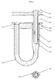
Fig. 1 is a cross section view of an embodiment of a waste heat boiler according to the invention, and -
Fig. 2 is a cross section view of a u-tube detail in an embodiment of a waste heat boiler according to the invention. -
- 101)
- Tube sheet
- 102)
- Tube sheet holes
- 103)
- Heat exchange u-tubes
- 104)
- Inlet tubes
- 105)
- Inlet tube plate
- 106)
- cooling medium side pressure shell
- 107)
- cooling medium chamber
- 108)
- cooling medium inlet nozzle
- 109)
- cooling medium outlet nozzle
- 110)
- Heating medium side pressure shell
- 111)
- Heating medium chamber
- 112)
- Heating medium inlet chamber
- 113)
- Heating medium outlet chamber
- 114)
- Heating medium inlet nozzle
- 115)
- Heating medium outlet nozzle
- 116)
- Inlet tube insulation
- The tube sheet (101) is on one side connected to the cooling medium side pressure shell (106) (e.g. water/steam) and on the other side connected to the heating medium side pressure shell (110) and forms the separation between the cooling medium chamber (107) and the heating medium chamber (111) (e.g. synthesis gas). The tube sheet is perforated with a number of tube sheet holes (102). The heat exchange u-tubes (103) are welded to the tube sheet (101) at both ends of the u-tubes in the tube sheet holes (102). The heat exchange u-tubes (103) extend into the cooling medium chamber (107). An inlet tube plate (105) is placed inside the heating medium chamber (111). The inlet tube plate (105) is perforated with holes corresponding to the holes in the tube sheet (101). Inlet tubes (104) with an outer diameter smaller than the inner diameter of the heat exchange u-tubes (103) are fixed to the holes of the inlet tube plate (105) and extend into the inside of the heat exchange u-tubes (103). The inlet tube plate (105) is connected to the heating medium nozzle (114) by means of plates and shells forming a gas tight heating medium inlet chamber (112). The inlet tubes (104) are covered with an inlet tube insulation layer (116).
- A cooling media as e.g. boiling feed water from a steam drum is flowing into the cooling medium chamber (107) through the cooling medium inlet nozzle (108) . The heat exchange u-tubes (103) are supplying heat for boiling in the cooling medium chamber (107). A mixture of water and steam is leaving the cooling medium chamber (107) through the cooling medium outlet nozzles (109). A heating medium as e.g. hot synthesis gas from an ammonia converter enters into the heating medium inlet chamber (111) through the heating medium inlet nozzle (114). The synthesis gas then flows through the holes of the inlet tube plate (105), through the inlet tubes (104) into the heat exchange u-tubes (103). In each heat exchange u-tube a first part of the synthesis gas flow is changing flow direction, returning in the u-tubes in the annulus, outside of the inlet tubes (104) and inside the heat exchange u-tubes (103), back to the heating medium outlet chamber (113). A second part of the synthesis gas flow in each heat exchange u-tube flows further on to the u-bend of the u-tube and flows to the heating medium outlet chamber (113). The synthesis gas then leaves the heat exchanger through the heating medium outlet nozzle (115).
- When the synthesis gas is flowing in the annulus between the inlet tube (104) and the heat exchange u-tube (103) it is cooled while it is transferring its heat by indirect heat transfer to the boiling water. Heat transfer between the inlet gas, flowing inside the inlet tubes (104) and the gas flowing in the annulus is avoided by means of the inlet tube insulation layer (116).
- The characteristic benefit of the heat exchanger according to the invention is that the thick tube sheet (101) will only come in contact with the cooled outlet synthesis gas. The problems experienced with synthesis gas waste heat boilers as described above related to the hot inlet gas and the temperature difference between tubes in the thick tube sheet is thereby minimized. The inlet tube plate (105) of the invention is thin because it is a non pressure part and it can be made of austenitic high alloy steel because it is not in contact with the water. The heat exchanger according to the invention has a reduced pressure drop as compared to blind tube heat exchangers as the gas stream is split in two when leaving the inlet tubes. The pressure drops and heat transfer coefficients of the first and the second gas streams flowing through a first and a second part and outlet of the u-tubes can be equilibrated in such a way that the synthesis gas temperature will be similar at both the u-tubes outlet ends. This may in one embodiment be done by reducing the diameter of the second end of the u-tubes as seen in
Fig. 2 .
Claims (15)
- A u-tube heat exchanger for heat exchanging a heating medium with a cooling medium, the heat exchanger comprising● a cooling medium chamber with an inlet and an outlet● a heating medium inlet chamber with an inlet● a heating medium outlet chamber with an outlet● a tube sheet with a plurality of tube sheet holes, the tube sheet separates the cooling medium chamber on a first side from the heating medium outlet chamber on the second side● a plurality of heat exchange u-tubes having a first and a second end● a plurality of inlet tubes having an inlet and an outlet end, each inlet tube corresponds to one of the u-tubes● an inlet tube plate arranged so that it separates the heating medium inlet chamber from the heating medium outlet chamber, the inlet tube plate has a plurality of inlet tube plate holessaid plurality of heat exchange u-tubes are arranged in the tube sheet with said first and second end connected to the circumference of a tube sheet hole each, the u-tubes extend within the cooling medium chamber in contact with the cooling medium on the shell side of the u-tubes, and said plurality of inlet tubes are arranged in the inlet tube plate with the inlet end connected to the circumference of an inlet tube plate hole each, wherein the outlet end of each of the inlet tubes is arranged partly within the first end of a corresponding heat exchange u-tube, the outside diameter of each inlet tube is smaller than the inside diameter of the corresponding heat exchange u-tubes first end in at least the part of each u-tube wherein the corresponding inlet tube is arranged within, the only fluid connection between the heating medium inlet chamber and the tube sheet and the inside of the u-tubes are via the fluid passage of the inlet tubes, whereby both the first and the second end of the u-tubes as well as the tube sheet are in contact with only the cooled heating medium on the tube side of the u-tubes and the tube sheet.
- A u-tube heat exchanger according to claim 1, wherein the cooling medium is water or steam, synthesis gas or process gas.
- A u-tube heat exchanger according to any of the preceding claims, wherein the heat exchanger is a waste heat boiler and the cooling medium is water or steam.
- A u-tube heat exchanger according to any of the preceding claims, wherein the heat exchanger is a synthesis gas waste heat boiler and the heating medium is synthesis gas.
- A u-tube heat exchanger according to any of the preceding claims, wherein the cooled heating medium exiting the first end of each of the plurality of u-tubes has a temperature substantially equal to the cooled heating medium exiting the second end of each of the plurality of u-tubes.
- A u-tube heat exchanger according to any of the preceding claims, wherein the temperature difference between the cooled heating medium exiting the first end of each of the plurality of u-tubes and the cooled heating medium exiting the second end of each of the plurality of u-tubes is in the range of 0°C - 50°C, preferably in the range of 0°C - 20°C.
- A u-tube heat exchanger according to any of the preceding claims, wherein at least the part of the plurality of inlet tubes arranged within a corresponding u-tube is thermally insulated.
- A u-tube heat exchanger according to any of the preceding claims, wherein there is an annulus between the part of each of the inlet tubes arranged within the first end of a corresponding heat exchange u-tube and the corresponding heat exchange u-tubes first end.
- A u-tube heat exchanger according to any of the preceding claims, wherein the plurality of inlet tubes are not in contact with the plurality of u-tubes.
- A u-tube heat exchanger according to any of the preceding claims wherein the diameter of the second end of each of the u-tubes is smaller than the diameter of the first end of said u-tube.
- A process for heat exchanging a heating medium with a cooling medium in a u-tube heat exchanger according to claim 1, the process comprising the steps ofa) providing a flow of the cooling medium via the cooling medium inlet into the cooling medium chamber, where the cooling medium contacts the shell side of the u-tubes, and out of the cooling medium chamber via the cooling medium outlet,b) providing a flow of the heating medium to the heating medium chamber via the heating medium inlet,c) providing the flow of the heating medium further through the holes of the inlet tube plate into the inlet tubes inlet ends, further through the inlet tubes and out of the inlet tubes outlet ends and into each of the corresponding u-tubes in a distance from said u-tubes first end,d) splitting the heating medium flow in each of the u-tubes in a first part flow which flows through a first part of each u-tube in the annulus between the inlet tube and the u-tube before the first part flow exits each u-tube via the first end and a second part flow which flows through a second part of each u-tube and exits each u-tube via the second end, both the first and the second part flow is in indirect heat-exchange with the cooling medium via the u-tubes walls and is cooled by the cooling medium while it flows through the u-tubese) collecting all the cooled heating medium flows in the heating medium outlet chamber where the cooled heating medium is in contact with the tube sheets second side and further providing a flow of the cooled heating medium out of the heating medium outlet chamber via the heating medium outlet.
- A process for heat exchanging a heating medium with a cooling medium according to claim 11, wherein the cooling medium is water or steam.
- A process for heat exchanging a heating medium with a cooling medium according to claim 11 or 12, wherein the cooling medium inlet temperature is in the range of 100°C - 350°C, preferably in the range of 250°C - 325°C, the cooling medium outlet temperature in the range of 100°C - 350°C, preferably in the range of 250°C - 325°C, the heating medium inlet temperature is in the range of 300°C - 500°C, preferably in the range of 390°C - 450°C, and the heating medium outlet temperature in the range of 120°C - 390°C, preferably in the range of 300°C - 370°C.
- A process for heat exchanging a heating medium with a cooling medium according to any of the claims 11 - 13, wherein the temperature difference between each of the first part cooled heating medium flows and the second part cooled heating medium flows is in the range of 0°C - 50°C, preferably in the range of 0°C - 20°C when exiting the first and the second end of each of the u-tubes into the heating medium outlet chamber.
- Use of a heat exchanger according to any of the claims 1 - 10 for heat exchanging water or steam with synthesis gas.
Priority Applications (1)
| Application Number | Priority Date | Filing Date | Title |
|---|---|---|---|
| PL11009291.3T PL2482020T5 (en) | 2011-01-31 | 2011-11-23 | Heat exchanger |
Applications Claiming Priority (1)
| Application Number | Priority Date | Filing Date | Title |
|---|---|---|---|
| DKPA201100061 | 2011-01-31 |
Publications (4)
| Publication Number | Publication Date |
|---|---|
| EP2482020A2 true EP2482020A2 (en) | 2012-08-01 |
| EP2482020A3 EP2482020A3 (en) | 2015-05-06 |
| EP2482020B1 EP2482020B1 (en) | 2019-09-04 |
| EP2482020B2 EP2482020B2 (en) | 2022-12-21 |
Family
ID=45217128
Family Applications (1)
| Application Number | Title | Priority Date | Filing Date |
|---|---|---|---|
| EP11009291.3A Active EP2482020B2 (en) | 2011-01-31 | 2011-11-23 | Heat exchanger |
Country Status (9)
| Country | Link |
|---|---|
| US (1) | US10767942B2 (en) |
| EP (1) | EP2482020B2 (en) |
| KR (1) | KR20120088523A (en) |
| CN (1) | CN102620580B (en) |
| AU (1) | AU2012200455B2 (en) |
| CA (1) | CA2759343C (en) |
| ES (1) | ES2748856T5 (en) |
| PL (1) | PL2482020T5 (en) |
| RU (1) | RU2599889C2 (en) |
Cited By (3)
| Publication number | Priority date | Publication date | Assignee | Title |
|---|---|---|---|---|
| EP3406999A1 (en) | 2017-05-26 | 2018-11-28 | ALFA LAVAL OLMI S.p.A. | Shell-and-tube heat exchanger |
| CN110186297A (en) * | 2019-07-02 | 2019-08-30 | 江苏晨力环保科技有限公司 | Acidproof heat exchanger |
| RU2700990C1 (en) * | 2018-12-04 | 2019-09-24 | Александр Геннадьевич Шершевский | Multistage shell-and-tube heat exchanger |
Families Citing this family (7)
| Publication number | Priority date | Publication date | Assignee | Title |
|---|---|---|---|---|
| CN105674775B (en) * | 2016-03-16 | 2017-10-20 | 福建邵化化工有限公司 | A kind of ammonia cooler cooling system for ammonia enterprise decarburization raw material air cooling |
| CN106006042A (en) * | 2016-06-30 | 2016-10-12 | 安徽泽加业粉体工程有限公司 | Pneumatic conveyor |
| CN106679467B (en) * | 2017-02-28 | 2019-04-05 | 郑州大学 | Shell-and-tube heat exchanger with external bobbin carriage |
| CN106855367B (en) * | 2017-02-28 | 2024-01-26 | 郑州大学 | Shell-and-tube heat exchanger with distributed inlets and outlets |
| CN110057210A (en) * | 2019-05-13 | 2019-07-26 | 燕河能源技术(北京)股份有限公司 | A kind of sewage source heat exchanger |
| CN110274512B (en) * | 2019-07-15 | 2024-05-03 | 北京凯瑞英科技有限公司 | Reactor system and process for precisely controlling thermal reaction temperature |
| DE102019120096A1 (en) * | 2019-07-25 | 2021-01-28 | Kelvion Machine Cooling Systems Gmbh | Shell and tube heat exchanger |
Citations (2)
| Publication number | Priority date | Publication date | Assignee | Title |
|---|---|---|---|---|
| US3568764A (en) | 1969-09-05 | 1971-03-09 | Daniel J Newman | Heat exchanger |
| EP0860673A2 (en) | 1997-02-21 | 1998-08-26 | Haldor Topsoe A/S | Synthesis gas waste heat boiler |
Family Cites Families (15)
| Publication number | Priority date | Publication date | Assignee | Title |
|---|---|---|---|---|
| US1918966A (en) | 1930-06-20 | 1933-07-18 | Gen Chemical Corp | Apparatus for treating gas |
| GB380548A (en) * | 1931-07-20 | 1932-09-22 | William Yorath Lewis | Improvements in heat-transfer apparatus applicable to water-tube boilers |
| US2502675A (en) * | 1946-12-23 | 1950-04-04 | Modine Mfg Co | Cleanable type heat exchanger |
| GB1148982A (en) * | 1966-07-05 | 1969-04-16 | Parsons C A & Co Ltd | Improvements in and relating to tubular heat exchangers |
| DE2804187C2 (en) | 1978-02-01 | 1980-04-03 | L. & C. Steinmueller Gmbh, 5270 Gummersbach | Heat exchanger with hanging U-tubes embedded in a plate for cooling process gases under high pressure and high temperature |
| JPS5677692A (en) * | 1979-11-27 | 1981-06-26 | Toyo Eng Corp | Heat exchanger |
| DE3022480A1 (en) * | 1980-06-14 | 1982-01-07 | Uhde Gmbh, 4600 Dortmund | DEVICE FOR EXCHANGING HEAT BETWEEN AN NH (DOWN ARROW) 3 (DOWN ARROW) CONVERTER LEAVING CYCLE GAS AND WATER |
| DE3049409C2 (en) † | 1980-12-23 | 1983-12-01 | Borsig Gmbh, 1000 Berlin | Equipment for steam generation in ammonia synthesis plants |
| US5436028A (en) | 1992-07-27 | 1995-07-25 | Motorola, Inc. | Method and apparatus for selectively applying solder paste to multiple types of printed circuit boards |
| CA2178524C (en) * | 1996-06-07 | 2007-07-03 | Howard John Lawrence | Boiler protection tube assembly |
| AU4090600A (en) * | 1999-06-30 | 2001-01-04 | Rohm And Haas Company | High performance heat exchangers |
| EP1600209B1 (en) * | 2004-05-29 | 2024-08-21 | Topsoe A/S | Heat exchange reactor |
| EP1724544A1 (en) | 2005-05-19 | 2006-11-22 | Balcke-Dürr GmbH | Method of heat exchanging and heat exchanger |
| DE102005057674B4 (en) | 2005-12-01 | 2008-05-08 | Alstom Technology Ltd. | waste heat boiler |
| WO2008003486A1 (en) | 2006-07-06 | 2008-01-10 | Behr Gmbh & Co. Kg | Exhaust gas cooler, in particular for a motor vehicle |
-
2011
- 2011-11-23 EP EP11009291.3A patent/EP2482020B2/en active Active
- 2011-11-23 PL PL11009291.3T patent/PL2482020T5/en unknown
- 2011-11-23 ES ES11009291T patent/ES2748856T5/en active Active
- 2011-11-24 CA CA2759343A patent/CA2759343C/en active Active
- 2011-12-01 US US13/309,123 patent/US10767942B2/en active Active
- 2011-12-23 KR KR1020110140974A patent/KR20120088523A/en not_active Application Discontinuation
-
2012
- 2012-01-27 AU AU2012200455A patent/AU2012200455B2/en active Active
- 2012-01-30 RU RU2012102917/06A patent/RU2599889C2/en active
- 2012-01-31 CN CN201210021465.6A patent/CN102620580B/en active Active
Patent Citations (2)
| Publication number | Priority date | Publication date | Assignee | Title |
|---|---|---|---|---|
| US3568764A (en) | 1969-09-05 | 1971-03-09 | Daniel J Newman | Heat exchanger |
| EP0860673A2 (en) | 1997-02-21 | 1998-08-26 | Haldor Topsoe A/S | Synthesis gas waste heat boiler |
Cited By (5)
| Publication number | Priority date | Publication date | Assignee | Title |
|---|---|---|---|---|
| EP3406999A1 (en) | 2017-05-26 | 2018-11-28 | ALFA LAVAL OLMI S.p.A. | Shell-and-tube heat exchanger |
| WO2018215160A1 (en) | 2017-05-26 | 2018-11-29 | Alfa Laval Olmi S.P.A | Shell-and-tube heat exchanger |
| US11054196B2 (en) | 2017-05-26 | 2021-07-06 | Alfa Laval Olmi S.P.A. | Shell-and-tube heat exchanger |
| RU2700990C1 (en) * | 2018-12-04 | 2019-09-24 | Александр Геннадьевич Шершевский | Multistage shell-and-tube heat exchanger |
| CN110186297A (en) * | 2019-07-02 | 2019-08-30 | 江苏晨力环保科技有限公司 | Acidproof heat exchanger |
Also Published As
| Publication number | Publication date |
|---|---|
| CA2759343A1 (en) | 2012-07-31 |
| RU2599889C2 (en) | 2016-10-20 |
| EP2482020B1 (en) | 2019-09-04 |
| US10767942B2 (en) | 2020-09-08 |
| US20120193082A1 (en) | 2012-08-02 |
| EP2482020B2 (en) | 2022-12-21 |
| AU2012200455B2 (en) | 2014-01-16 |
| CA2759343C (en) | 2019-02-12 |
| ES2748856T5 (en) | 2023-03-14 |
| AU2012200455A1 (en) | 2012-08-16 |
| ES2748856T3 (en) | 2020-03-18 |
| RU2012102917A (en) | 2013-08-10 |
| CN102620580A (en) | 2012-08-01 |
| CN102620580B (en) | 2016-12-14 |
| EP2482020A3 (en) | 2015-05-06 |
| KR20120088523A (en) | 2012-08-08 |
| PL2482020T5 (en) | 2023-03-27 |
| PL2482020T3 (en) | 2020-02-28 |
Similar Documents
| Publication | Publication Date | Title |
|---|---|---|
| EP2482020B1 (en) | Heat exchanger | |
| US10422529B2 (en) | Oxygen heat exchanger | |
| CA2510916C (en) | Heat exchange process and reactor | |
| EP2622297B1 (en) | Waste heat boiler | |
| JPS6042843B2 (en) | Waste heat boiler | |
| GB2588728A (en) | Ribbed tubeless heat exchanger for fliud heating systems including a rib component and methods of manufacture thereof | |
| EP3262363B1 (en) | Waste heat boiler system and method for cooling a process gas | |
| EP0860673A2 (en) | Synthesis gas waste heat boiler | |
| US9415364B2 (en) | Facility and reactor for directly synthesizing hydrochloric acid from hydrogen and chlorine with heat recovery | |
| Nandakumar et al. | Steam generators for future fast breeder reactors | |
| EP3143353B1 (en) | Heat exchange device for cooling synthetic gas and method of assembly thereof | |
| JP2018162917A (en) | Method for operating gas preheating device | |
| CN104620039B (en) | Method and apparatus for heated natural gas | |
| EP4390289A1 (en) | Heat exchanger with fluids in inverted counter-current configuration and operating method thereof | |
| KR20240127361A (en) | Tube sheet protection for process gas waste heat boiler | |
| Patel et al. | Review On Reliable Material For Heat Exchanger | |
| PEREZ | Hot Gas Heat Exchanger: A Better Design Improves Your Bottom Line |
Legal Events
| Date | Code | Title | Description |
|---|---|---|---|
| PUAI | Public reference made under article 153(3) epc to a published international application that has entered the european phase |
Free format text: ORIGINAL CODE: 0009012 |
|
| AK | Designated contracting states |
Kind code of ref document: A2 Designated state(s): AL AT BE BG CH CY CZ DE DK EE ES FI FR GB GR HR HU IE IS IT LI LT LU LV MC MK MT NL NO PL PT RO RS SE SI SK SM TR |
|
| AX | Request for extension of the european patent |
Extension state: BA ME |
|
| PUAL | Search report despatched |
Free format text: ORIGINAL CODE: 0009013 |
|
| AK | Designated contracting states |
Kind code of ref document: A3 Designated state(s): AL AT BE BG CH CY CZ DE DK EE ES FI FR GB GR HR HU IE IS IT LI LT LU LV MC MK MT NL NO PL PT RO RS SE SI SK SM TR |
|
| AX | Request for extension of the european patent |
Extension state: BA ME |
|
| RIC1 | Information provided on ipc code assigned before grant |
Ipc: F28D 7/06 20060101AFI20150331BHEP Ipc: F28D 21/00 20060101ALN20150331BHEP Ipc: F28F 19/00 20060101ALI20150331BHEP |
|
| 17P | Request for examination filed |
Effective date: 20150722 |
|
| RBV | Designated contracting states (corrected) |
Designated state(s): AL AT BE BG CH CY CZ DE DK EE ES FI FR GB GR HR HU IE IS IT LI LT LU LV MC MK MT NL NO PL PT RO RS SE SI SK SM TR |
|
| RAP1 | Party data changed (applicant data changed or rights of an application transferred) |
Owner name: HALDOR TOPSOEE A/S |
|
| STAA | Information on the status of an ep patent application or granted ep patent |
Free format text: STATUS: EXAMINATION IS IN PROGRESS |
|
| 17Q | First examination report despatched |
Effective date: 20170831 |
|
| GRAP | Despatch of communication of intention to grant a patent |
Free format text: ORIGINAL CODE: EPIDOSNIGR1 |
|
| STAA | Information on the status of an ep patent application or granted ep patent |
Free format text: STATUS: GRANT OF PATENT IS INTENDED |
|
| RIC1 | Information provided on ipc code assigned before grant |
Ipc: F28D 7/06 20060101AFI20190328BHEP Ipc: F28F 19/00 20060101ALI20190328BHEP Ipc: F28D 21/00 20060101ALN20190328BHEP |
|
| INTG | Intention to grant announced |
Effective date: 20190417 |
|
| GRAS | Grant fee paid |
Free format text: ORIGINAL CODE: EPIDOSNIGR3 |
|
| GRAA | (expected) grant |
Free format text: ORIGINAL CODE: 0009210 |
|
| STAA | Information on the status of an ep patent application or granted ep patent |
Free format text: STATUS: THE PATENT HAS BEEN GRANTED |
|
| AK | Designated contracting states |
Kind code of ref document: B1 Designated state(s): AL AT BE BG CH CY CZ DE DK EE ES FI FR GB GR HR HU IE IS IT LI LT LU LV MC MK MT NL NO PL PT RO RS SE SI SK SM TR |
|
| REG | Reference to a national code |
Ref country code: GB Ref legal event code: FG4D |
|
| REG | Reference to a national code |
Ref country code: CH Ref legal event code: EP |
|
| REG | Reference to a national code |
Ref country code: AT Ref legal event code: REF Ref document number: 1175962 Country of ref document: AT Kind code of ref document: T Effective date: 20190915 |
|
| REG | Reference to a national code |
Ref country code: DE Ref legal event code: R096 Ref document number: 602011061738 Country of ref document: DE |
|
| REG | Reference to a national code |
Ref country code: IE Ref legal event code: FG4D |
|
| REG | Reference to a national code |
Ref country code: NL Ref legal event code: FP |
|
| REG | Reference to a national code |
Ref country code: RO Ref legal event code: EPE |
|
| REG | Reference to a national code |
Ref country code: SE Ref legal event code: TRGR |
|
| REG | Reference to a national code |
Ref country code: NO Ref legal event code: T2 Effective date: 20190904 |
|
| REG | Reference to a national code |
Ref country code: LT Ref legal event code: MG4D |
|
| PG25 | Lapsed in a contracting state [announced via postgrant information from national office to epo] |
Ref country code: BG Free format text: LAPSE BECAUSE OF FAILURE TO SUBMIT A TRANSLATION OF THE DESCRIPTION OR TO PAY THE FEE WITHIN THE PRESCRIBED TIME-LIMIT Effective date: 20191204 Ref country code: HR Free format text: LAPSE BECAUSE OF FAILURE TO SUBMIT A TRANSLATION OF THE DESCRIPTION OR TO PAY THE FEE WITHIN THE PRESCRIBED TIME-LIMIT Effective date: 20190904 Ref country code: LT Free format text: LAPSE BECAUSE OF FAILURE TO SUBMIT A TRANSLATION OF THE DESCRIPTION OR TO PAY THE FEE WITHIN THE PRESCRIBED TIME-LIMIT Effective date: 20190904 Ref country code: FI Free format text: LAPSE BECAUSE OF FAILURE TO SUBMIT A TRANSLATION OF THE DESCRIPTION OR TO PAY THE FEE WITHIN THE PRESCRIBED TIME-LIMIT Effective date: 20190904 |
|
| REG | Reference to a national code |
Ref country code: SK Ref legal event code: T3 Ref document number: E 32728 Country of ref document: SK |
|
| PG25 | Lapsed in a contracting state [announced via postgrant information from national office to epo] |
Ref country code: AL Free format text: LAPSE BECAUSE OF FAILURE TO SUBMIT A TRANSLATION OF THE DESCRIPTION OR TO PAY THE FEE WITHIN THE PRESCRIBED TIME-LIMIT Effective date: 20190904 Ref country code: GR Free format text: LAPSE BECAUSE OF FAILURE TO SUBMIT A TRANSLATION OF THE DESCRIPTION OR TO PAY THE FEE WITHIN THE PRESCRIBED TIME-LIMIT Effective date: 20191205 Ref country code: RS Free format text: LAPSE BECAUSE OF FAILURE TO SUBMIT A TRANSLATION OF THE DESCRIPTION OR TO PAY THE FEE WITHIN THE PRESCRIBED TIME-LIMIT Effective date: 20190904 Ref country code: LV Free format text: LAPSE BECAUSE OF FAILURE TO SUBMIT A TRANSLATION OF THE DESCRIPTION OR TO PAY THE FEE WITHIN THE PRESCRIBED TIME-LIMIT Effective date: 20190904 |
|
| REG | Reference to a national code |
Ref country code: ES Ref legal event code: FG2A Ref document number: 2748856 Country of ref document: ES Kind code of ref document: T3 Effective date: 20200318 |
|
| PG25 | Lapsed in a contracting state [announced via postgrant information from national office to epo] |
Ref country code: EE Free format text: LAPSE BECAUSE OF FAILURE TO SUBMIT A TRANSLATION OF THE DESCRIPTION OR TO PAY THE FEE WITHIN THE PRESCRIBED TIME-LIMIT Effective date: 20190904 Ref country code: PT Free format text: LAPSE BECAUSE OF FAILURE TO SUBMIT A TRANSLATION OF THE DESCRIPTION OR TO PAY THE FEE WITHIN THE PRESCRIBED TIME-LIMIT Effective date: 20200106 |
|
| PG25 | Lapsed in a contracting state [announced via postgrant information from national office to epo] |
Ref country code: CZ Free format text: LAPSE BECAUSE OF FAILURE TO SUBMIT A TRANSLATION OF THE DESCRIPTION OR TO PAY THE FEE WITHIN THE PRESCRIBED TIME-LIMIT Effective date: 20190904 Ref country code: IS Free format text: LAPSE BECAUSE OF FAILURE TO SUBMIT A TRANSLATION OF THE DESCRIPTION OR TO PAY THE FEE WITHIN THE PRESCRIBED TIME-LIMIT Effective date: 20200224 Ref country code: SM Free format text: LAPSE BECAUSE OF FAILURE TO SUBMIT A TRANSLATION OF THE DESCRIPTION OR TO PAY THE FEE WITHIN THE PRESCRIBED TIME-LIMIT Effective date: 20190904 |
|
| REG | Reference to a national code |
Ref country code: DE Ref legal event code: R026 Ref document number: 602011061738 Country of ref document: DE |
|
| PLBI | Opposition filed |
Free format text: ORIGINAL CODE: 0009260 |
|
| PLAX | Notice of opposition and request to file observation + time limit sent |
Free format text: ORIGINAL CODE: EPIDOSNOBS2 |
|
| 26 | Opposition filed |
Opponent name: CASALE SA Effective date: 20200604 |
|
| PG2D | Information on lapse in contracting state deleted |
Ref country code: IS |
|
| PG25 | Lapsed in a contracting state [announced via postgrant information from national office to epo] |
Ref country code: DK Free format text: LAPSE BECAUSE OF FAILURE TO SUBMIT A TRANSLATION OF THE DESCRIPTION OR TO PAY THE FEE WITHIN THE PRESCRIBED TIME-LIMIT Effective date: 20190904 Ref country code: MC Free format text: LAPSE BECAUSE OF FAILURE TO SUBMIT A TRANSLATION OF THE DESCRIPTION OR TO PAY THE FEE WITHIN THE PRESCRIBED TIME-LIMIT Effective date: 20190904 Ref country code: LU Free format text: LAPSE BECAUSE OF NON-PAYMENT OF DUE FEES Effective date: 20191123 Ref country code: IS Free format text: LAPSE BECAUSE OF FAILURE TO SUBMIT A TRANSLATION OF THE DESCRIPTION OR TO PAY THE FEE WITHIN THE PRESCRIBED TIME-LIMIT Effective date: 20200105 |
|
| REG | Reference to a national code |
Ref country code: BE Ref legal event code: MM Effective date: 20191130 |
|
| PG25 | Lapsed in a contracting state [announced via postgrant information from national office to epo] |
Ref country code: SI Free format text: LAPSE BECAUSE OF FAILURE TO SUBMIT A TRANSLATION OF THE DESCRIPTION OR TO PAY THE FEE WITHIN THE PRESCRIBED TIME-LIMIT Effective date: 20190904 |
|
| PLBB | Reply of patent proprietor to notice(s) of opposition received |
Free format text: ORIGINAL CODE: EPIDOSNOBS3 |
|
| PG25 | Lapsed in a contracting state [announced via postgrant information from national office to epo] |
Ref country code: IE Free format text: LAPSE BECAUSE OF NON-PAYMENT OF DUE FEES Effective date: 20191123 Ref country code: FR Free format text: LAPSE BECAUSE OF NON-PAYMENT OF DUE FEES Effective date: 20191130 |
|
| PG25 | Lapsed in a contracting state [announced via postgrant information from national office to epo] |
Ref country code: BE Free format text: LAPSE BECAUSE OF NON-PAYMENT OF DUE FEES Effective date: 20191130 |
|
| PG25 | Lapsed in a contracting state [announced via postgrant information from national office to epo] |
Ref country code: CY Free format text: LAPSE BECAUSE OF FAILURE TO SUBMIT A TRANSLATION OF THE DESCRIPTION OR TO PAY THE FEE WITHIN THE PRESCRIBED TIME-LIMIT Effective date: 20190904 |
|
| PG25 | Lapsed in a contracting state [announced via postgrant information from national office to epo] |
Ref country code: MT Free format text: LAPSE BECAUSE OF FAILURE TO SUBMIT A TRANSLATION OF THE DESCRIPTION OR TO PAY THE FEE WITHIN THE PRESCRIBED TIME-LIMIT Effective date: 20190904 Ref country code: HU Free format text: LAPSE BECAUSE OF FAILURE TO SUBMIT A TRANSLATION OF THE DESCRIPTION OR TO PAY THE FEE WITHIN THE PRESCRIBED TIME-LIMIT; INVALID AB INITIO Effective date: 20111123 |
|
| REG | Reference to a national code |
Ref country code: AT Ref legal event code: UEP Ref document number: 1175962 Country of ref document: AT Kind code of ref document: T Effective date: 20190904 |
|
| PG25 | Lapsed in a contracting state [announced via postgrant information from national office to epo] |
Ref country code: TR Free format text: LAPSE BECAUSE OF FAILURE TO SUBMIT A TRANSLATION OF THE DESCRIPTION OR TO PAY THE FEE WITHIN THE PRESCRIBED TIME-LIMIT Effective date: 20190904 |
|
| APBM | Appeal reference recorded |
Free format text: ORIGINAL CODE: EPIDOSNREFNO |
|
| APBP | Date of receipt of notice of appeal recorded |
Free format text: ORIGINAL CODE: EPIDOSNNOA2O |
|
| APAH | Appeal reference modified |
Free format text: ORIGINAL CODE: EPIDOSCREFNO |
|
| PG25 | Lapsed in a contracting state [announced via postgrant information from national office to epo] |
Ref country code: MK Free format text: LAPSE BECAUSE OF FAILURE TO SUBMIT A TRANSLATION OF THE DESCRIPTION OR TO PAY THE FEE WITHIN THE PRESCRIBED TIME-LIMIT Effective date: 20190904 |
|
| APBU | Appeal procedure closed |
Free format text: ORIGINAL CODE: EPIDOSNNOA9O |
|
| PUAH | Patent maintained in amended form |
Free format text: ORIGINAL CODE: 0009272 |
|
| STAA | Information on the status of an ep patent application or granted ep patent |
Free format text: STATUS: PATENT MAINTAINED AS AMENDED |
|
| 27A | Patent maintained in amended form |
Effective date: 20221221 |
|
| AK | Designated contracting states |
Kind code of ref document: B2 Designated state(s): AL AT BE BG CH CY CZ DE DK EE ES FI FR GB GR HR HU IE IS IT LI LT LU LV MC MK MT NL NO PL PT RO RS SE SI SK SM TR |
|
| REG | Reference to a national code |
Ref country code: DE Ref legal event code: R102 Ref document number: 602011061738 Country of ref document: DE |
|
| PGFP | Annual fee paid to national office [announced via postgrant information from national office to epo] |
Ref country code: RO Payment date: 20221114 Year of fee payment: 12 |
|
| REG | Reference to a national code |
Ref country code: NO Ref legal event code: TB2 |
|
| REG | Reference to a national code |
Ref country code: SE Ref legal event code: RPEO |
|
| REG | Reference to a national code |
Ref country code: NL Ref legal event code: FP |
|
| REG | Reference to a national code |
Ref country code: ES Ref legal event code: DC2A Ref document number: 2748856 Country of ref document: ES Kind code of ref document: T5 Effective date: 20230314 |
|
| REG | Reference to a national code |
Ref country code: SK Ref legal event code: T5 Ref document number: E 32728 Country of ref document: SK |
|
| P01 | Opt-out of the competence of the unified patent court (upc) registered |
Effective date: 20230602 |
|
| PGFP | Annual fee paid to national office [announced via postgrant information from national office to epo] |
Ref country code: NL Payment date: 20231124 Year of fee payment: 13 |
|
| PGFP | Annual fee paid to national office [announced via postgrant information from national office to epo] |
Ref country code: SK Payment date: 20231113 Year of fee payment: 13 |
|
| PGFP | Annual fee paid to national office [announced via postgrant information from national office to epo] |
Ref country code: GB Payment date: 20231121 Year of fee payment: 13 |
|
| PGFP | Annual fee paid to national office [announced via postgrant information from national office to epo] |
Ref country code: ES Payment date: 20231218 Year of fee payment: 13 |
|
| PGFP | Annual fee paid to national office [announced via postgrant information from national office to epo] |
Ref country code: SE Payment date: 20231123 Year of fee payment: 13 Ref country code: NO Payment date: 20231120 Year of fee payment: 13 Ref country code: IT Payment date: 20231124 Year of fee payment: 13 Ref country code: DE Payment date: 20231127 Year of fee payment: 13 Ref country code: CH Payment date: 20231201 Year of fee payment: 13 Ref country code: AT Payment date: 20231117 Year of fee payment: 13 |
|
| PGFP | Annual fee paid to national office [announced via postgrant information from national office to epo] |
Ref country code: PL Payment date: 20231110 Year of fee payment: 13 |
|
| REG | Reference to a national code |
Ref country code: AT Ref legal event code: UEP Ref document number: 1175962 Country of ref document: AT Kind code of ref document: T Effective date: 20221221 |
|
| PG25 | Lapsed in a contracting state [announced via postgrant information from national office to epo] |
Ref country code: RO Free format text: LAPSE BECAUSE OF NON-PAYMENT OF DUE FEES Effective date: 20231123 |