EP2482003B1 - Refrigeration cycle device - Google Patents
Refrigeration cycle device Download PDFInfo
- Publication number
- EP2482003B1 EP2482003B1 EP09849772.0A EP09849772A EP2482003B1 EP 2482003 B1 EP2482003 B1 EP 2482003B1 EP 09849772 A EP09849772 A EP 09849772A EP 2482003 B1 EP2482003 B1 EP 2482003B1
- Authority
- EP
- European Patent Office
- Prior art keywords
- refrigerant
- compressor
- expander
- pressure
- piping
- Prior art date
- Legal status (The legal status is an assumption and is not a legal conclusion. Google has not performed a legal analysis and makes no representation as to the accuracy of the status listed.)
- Active
Links
- 238000005057 refrigeration Methods 0.000 title claims description 35
- 239000003507 refrigerant Substances 0.000 claims description 324
- 238000011144 upstream manufacturing Methods 0.000 claims description 7
- CURLTUGMZLYLDI-UHFFFAOYSA-N Carbon dioxide Chemical group O=C=O CURLTUGMZLYLDI-UHFFFAOYSA-N 0.000 claims description 6
- 229910002092 carbon dioxide Inorganic materials 0.000 claims description 3
- 239000001569 carbon dioxide Substances 0.000 claims description 3
- 238000004378 air conditioning Methods 0.000 description 86
- 238000001816 cooling Methods 0.000 description 41
- 238000010438 heat treatment Methods 0.000 description 29
- 238000010586 diagram Methods 0.000 description 27
- 238000000034 method Methods 0.000 description 25
- 230000008569 process Effects 0.000 description 23
- 239000007788 liquid Substances 0.000 description 19
- 230000007423 decrease Effects 0.000 description 12
- 230000002093 peripheral effect Effects 0.000 description 10
- 238000007906 compression Methods 0.000 description 8
- 230000006835 compression Effects 0.000 description 7
- 238000004781 supercooling Methods 0.000 description 6
- 230000008859 change Effects 0.000 description 4
- 230000000875 corresponding effect Effects 0.000 description 4
- 230000006837 decompression Effects 0.000 description 4
- 230000003247 decreasing effect Effects 0.000 description 3
- 239000012530 fluid Substances 0.000 description 3
- 230000000694 effects Effects 0.000 description 2
- 230000001771 impaired effect Effects 0.000 description 2
- 230000002265 prevention Effects 0.000 description 2
- CBENFWSGALASAD-UHFFFAOYSA-N Ozone Chemical compound [O-][O+]=O CBENFWSGALASAD-UHFFFAOYSA-N 0.000 description 1
- 230000002411 adverse Effects 0.000 description 1
- 239000012267 brine Substances 0.000 description 1
- KYKAJFCTULSVSH-UHFFFAOYSA-N chloro(fluoro)methane Chemical compound F[C]Cl KYKAJFCTULSVSH-UHFFFAOYSA-N 0.000 description 1
- 230000002596 correlated effect Effects 0.000 description 1
- 230000000368 destabilizing effect Effects 0.000 description 1
- 238000001514 detection method Methods 0.000 description 1
- 238000006073 displacement reaction Methods 0.000 description 1
- 238000003780 insertion Methods 0.000 description 1
- 230000037431 insertion Effects 0.000 description 1
- 239000010687 lubricating oil Substances 0.000 description 1
- 230000007246 mechanism Effects 0.000 description 1
- 239000000203 mixture Substances 0.000 description 1
- 239000003921 oil Substances 0.000 description 1
- 238000003825 pressing Methods 0.000 description 1
- 230000000630 rising effect Effects 0.000 description 1
- HPALAKNZSZLMCH-UHFFFAOYSA-M sodium;chloride;hydrate Chemical compound O.[Na+].[Cl-] HPALAKNZSZLMCH-UHFFFAOYSA-M 0.000 description 1
- 239000000243 solution Substances 0.000 description 1
- 238000010792 warming Methods 0.000 description 1
- XLYOFNOQVPJJNP-UHFFFAOYSA-N water Substances O XLYOFNOQVPJJNP-UHFFFAOYSA-N 0.000 description 1
Images


Classifications
-
- F—MECHANICAL ENGINEERING; LIGHTING; HEATING; WEAPONS; BLASTING
- F25—REFRIGERATION OR COOLING; COMBINED HEATING AND REFRIGERATION SYSTEMS; HEAT PUMP SYSTEMS; MANUFACTURE OR STORAGE OF ICE; LIQUEFACTION SOLIDIFICATION OF GASES
- F25B—REFRIGERATION MACHINES, PLANTS OR SYSTEMS; COMBINED HEATING AND REFRIGERATION SYSTEMS; HEAT PUMP SYSTEMS
- F25B1/00—Compression machines, plants or systems with non-reversible cycle
- F25B1/10—Compression machines, plants or systems with non-reversible cycle with multi-stage compression
-
- F—MECHANICAL ENGINEERING; LIGHTING; HEATING; WEAPONS; BLASTING
- F25—REFRIGERATION OR COOLING; COMBINED HEATING AND REFRIGERATION SYSTEMS; HEAT PUMP SYSTEMS; MANUFACTURE OR STORAGE OF ICE; LIQUEFACTION SOLIDIFICATION OF GASES
- F25B—REFRIGERATION MACHINES, PLANTS OR SYSTEMS; COMBINED HEATING AND REFRIGERATION SYSTEMS; HEAT PUMP SYSTEMS
- F25B11/00—Compression machines, plants or systems, using turbines, e.g. gas turbines
- F25B11/02—Compression machines, plants or systems, using turbines, e.g. gas turbines as expanders
-
- F—MECHANICAL ENGINEERING; LIGHTING; HEATING; WEAPONS; BLASTING
- F25—REFRIGERATION OR COOLING; COMBINED HEATING AND REFRIGERATION SYSTEMS; HEAT PUMP SYSTEMS; MANUFACTURE OR STORAGE OF ICE; LIQUEFACTION SOLIDIFICATION OF GASES
- F25B—REFRIGERATION MACHINES, PLANTS OR SYSTEMS; COMBINED HEATING AND REFRIGERATION SYSTEMS; HEAT PUMP SYSTEMS
- F25B13/00—Compression machines, plants or systems, with reversible cycle
-
- F—MECHANICAL ENGINEERING; LIGHTING; HEATING; WEAPONS; BLASTING
- F25—REFRIGERATION OR COOLING; COMBINED HEATING AND REFRIGERATION SYSTEMS; HEAT PUMP SYSTEMS; MANUFACTURE OR STORAGE OF ICE; LIQUEFACTION SOLIDIFICATION OF GASES
- F25B—REFRIGERATION MACHINES, PLANTS OR SYSTEMS; COMBINED HEATING AND REFRIGERATION SYSTEMS; HEAT PUMP SYSTEMS
- F25B2309/00—Gas cycle refrigeration machines
- F25B2309/06—Compression machines, plants or systems characterised by the refrigerant being carbon dioxide
- F25B2309/061—Compression machines, plants or systems characterised by the refrigerant being carbon dioxide with cycle highest pressure above the supercritical pressure
-
- F—MECHANICAL ENGINEERING; LIGHTING; HEATING; WEAPONS; BLASTING
- F25—REFRIGERATION OR COOLING; COMBINED HEATING AND REFRIGERATION SYSTEMS; HEAT PUMP SYSTEMS; MANUFACTURE OR STORAGE OF ICE; LIQUEFACTION SOLIDIFICATION OF GASES
- F25B—REFRIGERATION MACHINES, PLANTS OR SYSTEMS; COMBINED HEATING AND REFRIGERATION SYSTEMS; HEAT PUMP SYSTEMS
- F25B2313/00—Compression machines, plants or systems with reversible cycle not otherwise provided for
- F25B2313/027—Compression machines, plants or systems with reversible cycle not otherwise provided for characterised by the reversing means
- F25B2313/02742—Compression machines, plants or systems with reversible cycle not otherwise provided for characterised by the reversing means using two four-way valves
-
- F—MECHANICAL ENGINEERING; LIGHTING; HEATING; WEAPONS; BLASTING
- F25—REFRIGERATION OR COOLING; COMBINED HEATING AND REFRIGERATION SYSTEMS; HEAT PUMP SYSTEMS; MANUFACTURE OR STORAGE OF ICE; LIQUEFACTION SOLIDIFICATION OF GASES
- F25B—REFRIGERATION MACHINES, PLANTS OR SYSTEMS; COMBINED HEATING AND REFRIGERATION SYSTEMS; HEAT PUMP SYSTEMS
- F25B2400/00—General features or devices for refrigeration machines, plants or systems, combined heating and refrigeration systems or heat-pump systems, i.e. not limited to a particular subgroup of F25B
- F25B2400/04—Refrigeration circuit bypassing means
- F25B2400/0409—Refrigeration circuit bypassing means for the evaporator
-
- F—MECHANICAL ENGINEERING; LIGHTING; HEATING; WEAPONS; BLASTING
- F25—REFRIGERATION OR COOLING; COMBINED HEATING AND REFRIGERATION SYSTEMS; HEAT PUMP SYSTEMS; MANUFACTURE OR STORAGE OF ICE; LIQUEFACTION SOLIDIFICATION OF GASES
- F25B—REFRIGERATION MACHINES, PLANTS OR SYSTEMS; COMBINED HEATING AND REFRIGERATION SYSTEMS; HEAT PUMP SYSTEMS
- F25B2400/00—General features or devices for refrigeration machines, plants or systems, combined heating and refrigeration systems or heat-pump systems, i.e. not limited to a particular subgroup of F25B
- F25B2400/14—Power generation using energy from the expansion of the refrigerant
-
- F—MECHANICAL ENGINEERING; LIGHTING; HEATING; WEAPONS; BLASTING
- F25—REFRIGERATION OR COOLING; COMBINED HEATING AND REFRIGERATION SYSTEMS; HEAT PUMP SYSTEMS; MANUFACTURE OR STORAGE OF ICE; LIQUEFACTION SOLIDIFICATION OF GASES
- F25B—REFRIGERATION MACHINES, PLANTS OR SYSTEMS; COMBINED HEATING AND REFRIGERATION SYSTEMS; HEAT PUMP SYSTEMS
- F25B2400/00—General features or devices for refrigeration machines, plants or systems, combined heating and refrigeration systems or heat-pump systems, i.e. not limited to a particular subgroup of F25B
- F25B2400/16—Receivers
-
- F—MECHANICAL ENGINEERING; LIGHTING; HEATING; WEAPONS; BLASTING
- F25—REFRIGERATION OR COOLING; COMBINED HEATING AND REFRIGERATION SYSTEMS; HEAT PUMP SYSTEMS; MANUFACTURE OR STORAGE OF ICE; LIQUEFACTION SOLIDIFICATION OF GASES
- F25B—REFRIGERATION MACHINES, PLANTS OR SYSTEMS; COMBINED HEATING AND REFRIGERATION SYSTEMS; HEAT PUMP SYSTEMS
- F25B2500/00—Problems to be solved
- F25B2500/26—Problems to be solved characterised by the startup of the refrigeration cycle
-
- F—MECHANICAL ENGINEERING; LIGHTING; HEATING; WEAPONS; BLASTING
- F25—REFRIGERATION OR COOLING; COMBINED HEATING AND REFRIGERATION SYSTEMS; HEAT PUMP SYSTEMS; MANUFACTURE OR STORAGE OF ICE; LIQUEFACTION SOLIDIFICATION OF GASES
- F25B—REFRIGERATION MACHINES, PLANTS OR SYSTEMS; COMBINED HEATING AND REFRIGERATION SYSTEMS; HEAT PUMP SYSTEMS
- F25B2600/00—Control issues
- F25B2600/25—Control of valves
- F25B2600/2501—Bypass valves
-
- F—MECHANICAL ENGINEERING; LIGHTING; HEATING; WEAPONS; BLASTING
- F25—REFRIGERATION OR COOLING; COMBINED HEATING AND REFRIGERATION SYSTEMS; HEAT PUMP SYSTEMS; MANUFACTURE OR STORAGE OF ICE; LIQUEFACTION SOLIDIFICATION OF GASES
- F25B—REFRIGERATION MACHINES, PLANTS OR SYSTEMS; COMBINED HEATING AND REFRIGERATION SYSTEMS; HEAT PUMP SYSTEMS
- F25B2700/00—Sensing or detecting of parameters; Sensors therefor
- F25B2700/19—Pressures
- F25B2700/191—Pressures near an expansion valve
-
- F—MECHANICAL ENGINEERING; LIGHTING; HEATING; WEAPONS; BLASTING
- F25—REFRIGERATION OR COOLING; COMBINED HEATING AND REFRIGERATION SYSTEMS; HEAT PUMP SYSTEMS; MANUFACTURE OR STORAGE OF ICE; LIQUEFACTION SOLIDIFICATION OF GASES
- F25B—REFRIGERATION MACHINES, PLANTS OR SYSTEMS; COMBINED HEATING AND REFRIGERATION SYSTEMS; HEAT PUMP SYSTEMS
- F25B43/00—Arrangements for separating or purifying gases or liquids; Arrangements for vaporising the residuum of liquid refrigerant, e.g. by heat
- F25B43/006—Accumulators
Definitions
- the present invention relates to a refrigeration cycle apparatus using a refrigerant, such as a fluid that is brought into a supercritical state, and particularly, to a refrigeration cycle apparatus equipped with an expander that recovers the fluid energy as power during its expansion process.
- a refrigerant such as a fluid that is brought into a supercritical state
- a refrigeration cycle apparatus equipped with an expander that recovers the fluid energy as power during its expansion process for example, there is a refrigeration cycle apparatus equipped with a first compressor that is driven by an electric motor to compress refrigerant, a radiator that rejects the heat of the refrigerant compressed by the first compressor, an expander that decompresses the refrigerant that has passed through the radiator, an evaporator in which the refrigerant decompressed by the expander evaporates, and a second compressor that is driven by the expansion power recovered in the expander and has a discharge side connected to a suction side of the first compressor (for example, refer to Patent Literature 1).
- a refrigeration cycle apparatus equipped with a first compressor, a radiator that rejects the heat of refrigerant compressed by the first compressor, an expander that decompresses the refrigerant that has passed through the radiator, an evaporator in which the refrigerant decompressed by the expander evaporates, and a supercharger (a second compressor) that raises the pressure of the refrigerant evaporated in the evaporator and supplies the refrigerant to the first compressor (for example, refer to Patent Literature 2).
- a supercooling heat exchanger that supercools the refrigerant that flows out of the expander is provided on the discharge side of the expander, and in the supercooling heat exchanger, among a mainstream portion and a substream portion through which the refrigerant passes, one end of the substream portion is connected to a bypass piping bypassed from a piping that connects the expander and the mainstream portion via a supercooling expansion valve, and the other end of the substream portion is connected to a suction side of the first compressor.
- the efficiency of a refrigeration cycle can be improved by supercooling the refrigerant that flows out of the expander with the supercooling heat exchanger.
- a bypass path is provided to bypass the refrigerant to a suction side of the first compressor from a discharge side of the expander, and an opening/closing valve is provided in the bypass path.
- the invention has been made to solve the above problem, and an object thereof is to provide a refrigeration cycle apparatus that can stably recover power with an expander.
- a refrigeration cycle apparatus includes: a refrigeration cycle formed by sequentially connecting with pipes a first compressor that compresses a refrigerant, a radiator that rejects the heat of the refrigerant compressed by the first compressor, an expander that expands the refrigerant that has passed through the radiator and recovers power from the refrigerant, and an evaporator that evaporates the refrigerant expanded by the expander; a first bypass piping having one end connected to a discharge piping of the expander and the other end connected to a piping between the first compressor and the evaporator; physical quantity detecting means that detects a physical quantity of the refrigerant to be sucked into the expander; a first bypass valve provided in the first bypass piping to control the flow rate of the refrigerant; and control means that controls an opening degree of the first bypass valve, in which the control means determines an appropriate discharge pressure of the expander on the basis of the physical quantity detected by the physical quantity detecting means and opens the first bypass valve when an
- the first bypass valve is opened to bypass the refrigerant from the discharge piping of the expander to the suction side of the first compressor.
- the discharge pressure of the expander can be made low. This can prevent the expander from overexpanding and can stabilize the rotation of the expander.
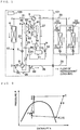
- Fig. 1 is a refrigerant circuit diagram during a cooling operation of an air-conditioning apparatus equipped with a refrigeration cycle apparatus according to Embodiment 1 of the invention.
- Fig. 2 is a refrigerant circuit diagram during the cooling operation of the air-conditioning apparatus of Fig. 1 .
- the air-conditioning apparatus of Fig. 1 is equipped with a refrigeration cycle apparatus that is formed by sequentially connecting by means of piping a first compressor 1 that is driven by an electric motor to compress a refrigerant, a second compressor 2, an outdoor heat exchanger 4, an expander 8 that expands the refrigerant that passes therethrough and recovers power from the refrigerant, and an indoor heat exchanger 32.
- the second compressor 2 and the expander 8 are coupled together with a drive shaft 52, and the second compressor 2 is driven via the drive shaft 52 by the power recovered by the expander 8.
- the outdoor heat exchanger 4 becomes a radiator in which an internal refrigerant rejects heat during a cooling operation, and becomes an evaporator in which the internal refrigerant evaporates during a heating operation. Additionally, the indoor heat exchanger 32 becomes an evaporator in which the internal refrigerant evaporates during a cooling operation, and becomes a radiator in which the internal refrigerant rejects heat during a heating operation.
- this air-conditioning apparatus is equipped with a bypass piping 24 that bypasses the refrigerant to an inlet piping 27 of an accumulator 11 from a discharge piping 23 of the expander 8, and a bypass valve 10 that adjusts the flow rate of the refrigerant that flows through the bypass piping 24.
- carbon dioxide is used as the refrigerant, and as compared to conventional chlorofluorocarbon refrigerants, this carbon dioxide has zero ozone depletion potential and a low global warming potential.
- the first compressor 1, the second compressor 2, a first four-way valve 3 that is a refrigerant flow switching device, the outdoor heat exchanger 4, a second four-way valve 6 that is a refrigerant flow switching device, a pre-expansion valve 7, the expander 8, a bypass valve 5, the bypass valve 10, and the accumulator 11 are accommodated in an outdoor unit 101.
- An expansion valve 31a and an indoor heat exchanger 32a are accommodated in an indoor unit 102a, and an expansion valve 31b and an indoor heat exchanger 32b are accommodated in an indoor unit 102b.
- a control device 103 that controls the overall control of the air-conditioning apparatus is also accommodated in the outdoor unit 101.
- the number of the indoor units 102 (indoor heat exchangers 32) is set to two in Embodiment 1, the number of the indoor units 102 is arbitrary.
- the outdoor unit 101 and the indoor units 102a and 102b are connected together by a liquid pipe 28 and a gas pipe 29.
- the first compressor 1 is driven by an electric motor (not shown) to compress and discharge the sucked-in refrigerant.
- the second compressor 2 and the expander 8 are accommodated in a container 51.
- the second compressor 2 is connected to the expander 8 via the drive shaft 52, and power generated in the expander 8 is recovered by the drive shaft 52 and is transferred to the second compressor 2.
- the second compressor 2 sucks in the refrigerant discharged from the first compressor 1, and further compresses the refrigerant.
- the first four-way valve 3 is provided in a refrigerant channel between the outdoor heat exchanger 4, the second compressor 2, the indoor heat exchanger 32, and the accumulator 11. Additionally, the second four-way valve 6 is provided in a refrigerant channel between the outdoor heat exchanger 4, the expander 8, and the indoor heat exchanger 32. The first four-way valve 3 and the second four-way valve 6 are switched corresponding to the cooling or heating operation mode, on the basis of an instruction from the control device 103, and switch the refrigerant path.
- the refrigerant flows sequentially from the second compressor 2 to the outdoor heat exchanger 4, the expander 8, the indoor heat exchanger 32, the accumulator 11, and the first compressor 1, and returns to the second compressor 2.
- the refrigerant flows sequentially from the second compressor 2 to the indoor heat exchanger 32, the expander 8, the outdoor heat exchanger 4, the accumulator 11, and the first compressor 1, and returns to the second compressor 2.
- the flow direction of the refrigerant that passes through the expander 8 and the second compressor 2 are made to be the same irrespective of the cooling operation and the heating operation by the first four-way valve 3 and second four-way valve 6.
- the outdoor heat exchanger 4 has, for example, a heat transfer tube through which the refrigerant flows and fins (not shown) for increasing the heat transfer area between the refrigerant that flows through the heat transfer tube and outdoor air, and exchanges heat between the refrigerant and air (outdoor air).
- the outdoor heat exchanger functions as an evaporator during a heating operation, and evaporates the refrigerant and gasifies it.
- the outdoor heat exchanger functions as a condenser or a gas cooler (hereinafter referred to as a condenser) during a cooling operation.
- the outdoor heat exchanger does not gasify or liquefy the refrigerant completely, but brings the refrigerant into a two-phase mixture (gas-liquid two-phase refrigerant) state of liquid and gas.
- the accumulator 11 functions to reserve excess refrigerant in a refrigeration cycle or to prevent the first compressor 1 being damaged by return of liquid refrigerant to the first compressor 1 in large quantities.
- a refrigerant channel 22 between the second four-way valve 6 and an inlet of the expander 8 is provided with the pre-expansion valve 7 that adjusts the flow rate of the refrigerant that passes through the expander 8.
- a refrigerant channel 23 between an outlet of the expander 8 and the second four-way valve 6 is provided with a check valve 9 that arranges the direction in which the refrigerant flows to be one direction.
- a refrigerant channel between the outdoor heat exchanger 4 and the indoor heat exchanger 32 is provided with a bypass piping 25 that bypasses the second four-way valve 6, the pre-expansion valve 7, the expander 8, and the check valve 9, and the bypass valve 5 that adjusts the flow rate of the refrigerant that passes through the bypass piping 25.
- the flow rate of the refrigerant that passes through the expander can be adjusted to control the pressure on a high-pressure side, and maintain a refrigeration cycle in a highly efficient state. It should be noted that the pressure on the high-pressure side may be controlled by other methods, without being limited to the adjustment of the pre-expansion valve 7 and the bypass valve 5.
- bypass piping 24 that bypasses the expansion valve 31 and the indoor heat exchanger 32, and the bypass valve 10 that adjusts the flow rate of the refrigerant that passes through the bypass piping 24 are provided between the refrigerant outlet of the expander 8 and the refrigerant inlet of the accumulator 11.
- a refrigerant outlet of the second compressor 2 is provided with a pressure sensor 81 that detects the pressure of the refrigerant that has come out of the second compressor 2
- the refrigerant outlet of the expander 8 is provided with a pressure sensor 82 that detects the pressure of the refrigerant that has come out of the expander 8
- the refrigerant channel between the second four-way valve 6 and expansion valve 31 is provided with a pressure sensor 83 that detects the pressure of the refrigerant that flows into the expansion valve 31 or the pressure of the refrigerant that has come out of the expansion valve 31
- a refrigerant inlet of the first compressor 1 is provided with a pressure sensor 84 that detects the pressure of the refrigerant that flows into the first compressor 1
- the refrigerant inlet of the expander 8 is provided with a pressure sensor 85 that detects the pressure of the refrigerant that flows into the expander 8.
- the positions of the pressure sensors 81, 82, 83, 84, and 85 are not limited to the above as long as they are positioned to where the pressure of the refrigerant that has come out of the second compressor 2, the pressure of the refrigerant that has come out of the expander 8, the pressure of the refrigerant that flows into the expansion valve 31 or the pressure of the refrigerant that has come out of the expansion valve 31, the pressure of the refrigerant that flows into the first compressor 1, and the pressure of the refrigerant that flows into the expander 8 can be respectively detected.
- the pressure sensors 81, 82, 83, 84, and 85 may be temperature sensors that estimate the temperature of the refrigerant.
- the refrigerant inlet of the expander 8 is provided with a temperature sensor 91 that detects the temperature of the refrigerant that flows into the expander 8 and the a piping between the outdoor heat exchanger 4, and the second four-way valve 6 and the bypass valve 5 is provided with a temperature sensor 92 that detects the temperature of the refrigerant that has come out of the outdoor heat exchanger 4 or the refrigerant that flows into the outdoor heat exchanger 4.
- the position of the temperature sensors 91 and 92 are not limited to the above as long as they are positioned to where the temperature of the refrigerant that flows into the expander 8, and the temperature of the refrigerant that flows into the outdoor heat exchanger 4 or the refrigerant that has come out of the outdoor heat exchanger 4 can be respectively detected.
- the indoor heat exchanger 32 has, for example, a heat transfer tube through which the refrigerant flows and fins (not shown) for increasing the heat transfer area between the refrigerant that flows through the heat transfer tube and outdoor air, and exchanges heat between the refrigerant and air (outdoor air).
- the indoor heat exchanger functions as an evaporator during a cooling operation, and evaporates the refrigerant and gasifies it.
- the indoor heat exchanger functions as a condenser or a gas cooler (hereinafter referred to as a condenser) during a heating operation.
- the expansion valve 31a is connected to the indoor heat exchanger 32a, and the expansion valve 31 b is connected to the indoor heat exchanger 32b.
- the expansion valves 31a and 31b control the flow rates of refrigerants that flow into the indoor heat exchangers 32a and 32b. When the refrigerant is not sufficiently decompressed by the expander 8, the expansion valves 31a and 31b adjust the high-low pressure.
- a low-pressure refrigerant sucked into the first compressor 1 is compressed and becomes high in temperature and medium in pressure (from State A to State B).
- the refrigerant discharged from the first compressor 1 is sucked into the second compressor 2, and is further compressed so as to become high in temperature and high in pressure (from State B to State C).
- the refrigerant discharged from the second compressor 2 passes through the first four-way valve 3, and flows into the outdoor heat exchanger 4.
- the refrigerant that has radiated heat and transferred heat to the outdoor air in the outdoor heat exchanger 4 becomes low in temperature and high in pressure (from State C to State D).
- the refrigerant that has come out of the outdoor heat exchanger 4 branches into a path directed to the second four-way valve 6 and a path directed to the bypass valve 5.
- the refrigerant that has passed through the second four-way valve 6 passes through the pre-expansion valve 7 (from State D to State E), is sucked into and decompressed to Low Pressure by the expander 8, and becomes low in dryness (from State E to State F).
- the refrigerant discharged from the expander 8 passes through the check valve 9 and the second four-way valve 6, the refrigerant flows toward the bypass valve 5 and merges with the refrigerant that has passed through the bypass piping 25 (from State F to State G), comes out of the outdoor unit 101, and passes through the liquid pipe 28, flows into the indoor units 102a and 102b, and flows into the expansion valves 31a and 31b.
- the refrigerant is further decompressed in the expansion valves 31a and 31b (from State G to State I).
- the refrigerant that has come out of the expansion valves 31a and 31b removes heat from the indoor air and evaporates in the indoor heat exchangers 32a and 32b, and becomes high in dryness while still low in pressure(from State I to State J).
- the heat of the indoor air is transferred to the outdoor air, and the interior of a room is cooled.
- a low-pressure refrigerant sucked into the first compressor 1 is compressed, and becomes high in temperature and medium in pressure (from State A to State B).
- the refrigerant discharged from the first compressor 1 is sucked into the second compressor 2, and is further compressed so as to become high in temperature and high in pressure (from State B to State J).
- the refrigerant discharged from the second compressor 2 passes through the first four-way valve 3, and comes out of the outdoor unit 101.
- the refrigerant that has come out of the outdoor unit 101 passes through the gas pipe 29, flows into the indoor units 102a and 102b, and flows into the indoor heat exchangers 32a and 2b.
- the refrigerant that has rejected heat and transferred heat to indoor air in the indoor heat exchangers 32a and 32b becomes low in temperature and high in pressure (from State J to State I).
- the refrigerant that has come out of the indoor heat exchangers 32a and 32b is decompressed in the expansion valves 31a and 31b (from State I to State G).
- the refrigerant that has come out of the expansion valves 31a and 31b comes out of the indoor units 102a and 102b, passes through the liquid pipe 28, flows into the outdoor unit 101, and branches into the path directed to the second four-way valve 6 and the path directed to the bypass valve 5.
- the refrigerant that has passed through the second four-way valve 6 passes through the pre-expansion valve 7 (from State G to State E), flows into and is decompressed to Low Pressure by the expander 8, and becomes low in dryness (from State E to State F).
- power is generated with the decompression of the refrigerant, is recovered by the drive shaft 52, is transferred to the second compressor 2, and is used to compress the refrigerant with the second compressor 2.
- the refrigerant removes heat from the outdoor air and evaporates, and becomes high in dryness while still low in pressure (from State D to State C).
- the refrigerant that has come out of the outdoor heat exchanger 4 passes through the first four-way valve 3, flows into the accumulator 11, and is again sucked into the first compressor 1.
- the heat of the outdoor air is transferred to the indoor air, and the interior of a room is heated.
- a scroll expander 8 and a second scroll compressor 2 as examples of the second compressor 2 and the expander 8 will be described.
- the second compressor 2 and the expander 8 may be other positive displacement types without being limited to the scroll type.
- Fig. 5 is a cross-sectional view of the scroll expander 8 integral with the second compressor 2.
- the expander 8 that expands the refrigerant and recovers power is composed of spiral teeth 67 of a fixed scroll 59 of the expander, and spiral teeth 65 on the bottom face of an orbiting scroll 57.
- the second compressor 2 that compresses the refrigerant by the power recovered in the expander 8 is composed of spiral teeth 66 of a fixed scroll 58 of the compressor, and spiral teeth 64 on the top face of the orbiting scroll 57.
- spiral teeth 65 of the expander 8 and the spiral teeth 64 of the second compressor 2 are integrally formed back to back on two faces of a common base plate in the orbiting scroll 57, compression can take place on one side and expansion can take place on the other side, when the orbiting scroll 57 is driven.
- a high-temperature and medium-pressure refrigerant discharged from the first compressor 1 is sucked into a suction pipe 53 of the second compressor 2, and is introduced into the outer peripheral side of the second compressor 2 formed by the spiral teeth 66 of the fixed scroll 58 of the compressor, and the spiral teeth 64 of the orbiting scroll 57. Then, by the orbiting of the orbiting scroll 57, the refrigerant is gradually moved to the inner peripheral side in the second compressor 2 and is compressed to high temperature and High Pressure. The compressed refrigerant is discharged from a discharge pipe 54 of the second compressor 2.
- a high-pressure refrigerant cooled in the outdoor heat exchanger 4 or the indoor heat exchanger 32 is sucked into a suction pipe 55 of the expander 8, and is introduced into the inner peripheral side of the expander 8 formed by the spiral teeth 67 of the fixed scroll of the expander and the spiral teeth 65 of the orbiting scroll 57. Then, by the orbiting of the orbiting scroll 57, the refrigerant is gradually moved to the outer peripheral side in the expander 8 and is expanded into Low Pressure.
- the expanded refrigerant is discharged from a discharge pipe 56 of the expander 8.
- the expansion power of the refrigerant in the expander 8 is recovered via the drive shaft 52, is transferred to the second compressor 2, and is used as compression power.
- the afore-mentioned mechanism constituted by the second compressor 2 and the expander 8 is accommodated in the container 51.
- FIG. 6 schematically shows distribution of the thrust loads of the second compressor 2 and the expander 8 that act on the second compressor 2 side and the expander side at design points of the second compressor 2.
- the thrust load that acts on the second compressor 2 side is force that presses the orbiting scroll 57 towards the fixed scroll 59 of the expander 8.
- the thrust load that acts on the expander 8 side is force that presses the orbiting scroll 57 towards the fixed scroll 58 of the second compressor 2.
- the discharge pressure of the second compressor 2 will be denoted as High Pressure
- the suction pressure of the second compressor 2 will be denoted as Medium Pressure
- the discharge pressure of the expander 8 will be denoted as Low Pressure.
- the reference pressure of the pressing force will be the Low Pressure.
- a thrust load that acts on the second compressor 2 by the refrigerant compressed by the second compressor 2 will be obtained.
- the area in which the orbiting scroll 57 receives the load from the refrigerant compressed in the second compressor 2 is defined as Sc [mm 2 ].
- the thrust load Fthc [N] of the second compressor 2 may be obtained by Formula (1).
- Fthc PH + PM ⁇ 2 PL / 2 ⁇ Sc
- the thrust load that acts on the expander 8 by the refrigerant that expands in the expander 8 will be obtained.
- the area in which the orbiting scroll 57 receives the load from the refrigerant that expands in the expander 8 is defined as Se [mm 2 ]. Since the outer peripheral side of the expander 8 is the same Low Pressure as the reference pressure, supposing 1/2 of High Pressure PH-Low Pressure PL [MPa], which is a difference between the pressure on the inner peripheral side and the reference pressure, acts on the area Se, the thrust load Fthe [N] of the expander 8 may be obtained by Formula (2).
- Fthe PH ⁇ PL / 2 ⁇ Se
- the balance of the flow rates between the expander 8 and the second compressor 2 may be disrupted, and the rotation of the second compressor 2 and the expander 8 may become unstable.
- the transitional decrease of the rotational frequency of the second compressor 2 and the expander 8 act as resistance against circulation of the refrigerant and the High Pressure will rise.
- Fig. 8 is a P-v diagram during an appropriate expansion process in which the outlet of the expander 8 is brought into a state F
- Fig. 9 is a P-v diagram during an overexpansion process in which the outlet of the expander 8 is brought into a state F2.
- the refrigerant is sucked in the state of pressure PH and volume Vei and is separated, by the spiral teeth 67 of the fixed scroll of the expander and the spiral teeth 65 of the orbiting scroll 57, and the separated refrigerant is decompressed while volume V increases.
- Po is a state in which the pressure is the lowest inside the expander. Po is the pressure obtained by the suction pressure PH of the expander 8 and the expansion volume ratio Vi/Vo of the expander 8, supposing that adiabatic expansion occurs inside the expander 8.
- the refrigerant separated by the spiral teeth 67 of the fixed scroll 59 of the expander and the spiral teeth 65 of the orbiting scroll 57, passes through the discharge pipe 56 of the expander 8, and is opened to Low Pressure PL.
- the pressure Po at which expansion ends and the Low Pressure PL are almost equal.
- the discharge pressure PL2 of the expander 8 is higher than Po2 (appropriate discharge pressure) at which the pressure becomes the lowest during the expansion process of the expander 8.
- Po2 appropriate discharge pressure
- the discharge pressure PL2 of the expander 8 being higher than the appropriate discharge pressure Po2 is referred to as overexpansion.
- the operation of appropriately reducing the discharge pressure of the expander 8 may be performed such that the discharge pressure of the expander 8 does not become higher than the appropriate discharge pressure.
- Fig. 10 schematically shows the distribution of thrust loads of the second compressor 2 and the expander 8 that act on the second compressor 2 side and the expander 8 side, when the High Pressure is PH2, the Medium Pressure is PM2, and the Low Pressure is PL2.
- a thrust load Fthc2 [N] that acts on the second compressor 2 side of the orbiting scroll 57 may be obtained by Formula (5), in the same way as Formula (1).
- Fthc 2 PH 2 + PM 2 ⁇ 2 PL 2 / 2 ⁇ Sc
- the pressure of the outer periphery of the orbiting scroll 57 on the expander 8 side is the pressure Po2 at which expansion ends, which is lower than the Low Pressure PL2. That is, since force in an opposite direction to the inner peripheral side acts on the outer peripheral side of the orbiting scroll 57, a thrust load Fthe2 that acts on the spiral teeth 65 of the orbiting scroll 57 is expressed by Inequality (6), which is smaller than that obtained by Formula (2).
- the discharge pressure of the expander 8 is reduced by the following method, preventing overexpansion during the expansion process in the expander 8.
- the bypass piping 24 that bypasses the refrigerant from the discharge piping 23 of the expander 8 to the inlet piping 27 of the accumulator 11 is provided, and the bypass valve 10 that adjusts the bypass amount of the refrigerant to the bypass piping 24 is provided.
- the discharge pressure of the expander 8 can be reduced, and further, overexpantion can be prevented during the expansion process in the expander 8.
- the check valve 9 is provided further downstream than a connection port of the bypass piping 24 in the discharge piping 23 of the expander 8. As is clear from Fig. 2 , between the state F of the refrigerant on the inlet side of the check valve 9 and the state G of the refrigerant on the outlet side, the state G is higher in pressure. Although the refrigerant flows to a lower pressure side from a higher pressure side, this is prevented by the check valve 9. That is, the check valve 9 prevents the refrigerant that has passed through the bypass piping 25 from flowing from Point G to Point F in Fig. 1 , from passing through the bypass piping 24, and from flowing into the accumulator 11.
- the discharge pressure of the expander 8 can be made low even if the air-conditioning apparatus is operating in a state in which the discharge pressure of the expander 8 becomes high.
- Fig. 11 is a flowchart showing the operation of preventing the expander from overexpanding, in the air-conditioning apparatus according to Embodiment 1.
- the pressure P detected by a certain pressure sensor may be, using the symbol of the pressure sensor, designated as P(symbol) (for example, P(83) in the case of the pressure sensor 83).
- the air-conditioning apparatus periodically checks the operation of the expander 8 during regular control, such as a usual cooling operation and heating operation, and operates to prevent the expander 8 from overexpanding. That is, the control device 103 determines whether or not a predetermined time period has elapsed during regular control (Step S101). After the predetermined time period has elapsed, the value of the pressure P(82) detected by the pressure sensor 82 is determined whether it is higher than the discharge pressure (appropriate discharge pressure) Po of the expander 8 when undergoing appropriate expansion (Step S102).
- This appropriate discharge pressure Po is determined from the present suction pressure and suction temperature of the expander 8, and the relational data, which is stored in advance in the control device 103, between the suction temperature and the appropriate discharge pressure Po of each suction pressure of the expander 8.
- Step S104 the control device 103 increases an opening degree L10 of the bypass valve 10 provided in the bypass piping 24 by a preset amount ⁇ L, thereby increasing the flow rate of the refrigerant that flows to the bypass piping 24 (Step S103).
- the discharge pressure P(82) of the expander 8 can be lowered.
- a control device 102 ends the operation preventing overexpansion by closing the bypass valve 10 when it is determined in Step S103 that P(82) has become lower than Po.
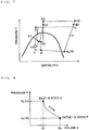
- Fig. 12 shows the relationship between the suction pressure and the appropriate discharge pressure when the suction pressure is 10 MPa, 9 MPa, and 8 MPa.
- a specific suction volume is determined from the suction pressure and suction temperature of the expander 8. Additionally, since the relationship between the suction volume Vi and discharge volume Vo of the expander 8 is constant, a specific volume when an expansion process is completed is determined from the specific suction volume of the expander 8.
- the appropriate discharge pressure Po can be approximately calculated from the specific volume.
- the appropriate discharge pressure Po according to the suction pressure and suction temperature of the expander 8 can be approximately estimated from the pressure detected by the pressure sensor 85, which is the suction pressure of the expander 8, the temperature detected by the temperature sensor 91, which is the suction temperature, and the relationship diagram shown in Fig. 12 , which is stored in advance by the control device 103.
- the refrigerant that has come out of the outdoor heat exchanger 4 branches into a path directed to the second four-way valve 6 and a path directed to the bypass valve 5.
- the refrigerant that has passed through the second four-way valve 6 passes through the pre-expansion valve 7 (from State D3 to State E3), is sucked into and decompressed to Low Pressure by the expander 8, and becomes low in dryness (from State E3 to State F3).
- the refrigerant discharged from the expander 8 flows into the bypass piping 24 from the discharge piping 23 of the expander 8. Then, the refrigerant is further decompressed by the bypass valve 10 (from State F3 to State M).
- the refrigerant (from State D3 to State G3) that has passed through the bypass valve 5 and been decompressed comes out of the outdoor unit 101, passes through the liquid pipe 28, flows into the indoor units 102a and 102b, and flows into the expansion valves 31a and 31b.
- State G3 of the refrigerant after passing through the bypass valve 5 and State F3 of the refrigerant after passing through the expander 8 are compared, the refrigerant pressure in State G3 is higher.
- the refrigerant flows into the lower pressure side from the higher pressure side, since the check valve 9 is provided here as described above, the refrigerant does not flow to a channel between Point G and Point F of Fig. 1 , and all the refrigerant that has passed the bypass valve 5 flows to channels directed to the indoor units 102a and 102b side.
- the refrigerant is further decompressed (from State G3 to State 13).
- the refrigerant that has come out of the expansion valves 31a and 31b removes heat from the indoor air and evaporates in the indoor heat exchangers 32a and 32b, and becomes high in dryness while still in a low-pressure state (from State I3 to State J).
- the refrigerant that has come out of the accumulator 11 is again sucked into the first compressor 1.
- the bypass valve 10 when the bypass valve 10 is opened to flow the refrigerant discharged from the expander 8 into the accumulator 11, the suction pressure of the first compressor 1 may rise.
- the opening degree of the pre-expansion valve 7 when opening the bypass valve 10, the opening degree of the pre-expansion valve 7 may be made small to make the suction pressure of the expander 8 low. Additionally, since the refrigerant that flows through the expander 8 decreases when the opening degree of the pre-expansion valve 7 is made small, the bypass valve 5 may be opened in this case.
- the check valve 9 is provided further downstream than a connection port of the bypass piping 24 in the discharge piping 23 of the expander 8, the refrigerant that flows through the bypass piping 25 can be prevented from passing through the bypass piping 24 and flowing into the accumulator 11.
- Fig. 14 is a P-v diagram showing an expansion process when the suction pressure of the expander is low.
- the refrigerant discharged from the expander 8 is a low-temperature and low-pressure gas-liquid two-phase refrigerant. If the first compressor 1 directly sucks in this refrigerant, the first compressor 1 performs liquid compression. As a result, the reliability of the compressor is impaired.
- the refrigerant that flows through the bypass piping 24 is connected to the inlet piping 27 of the accumulator 11. Therefore, the gas-liquid two-phase refrigerant can be reserved in the accumulator 11 even if the gas-liquid two-phase refrigerant flows to the bypass piping 24. Therefore, the first compressor 1 can be prevented from performing liquid compression.
- Embodiment 1 even if, due to the operating state of the air-conditioning apparatus, the expansion process of the expander 8 transitionally becomes overexpanded during the expansion process of the expander 8 increasing the thrust loads that act on the second compressor 2 and the expander 8, and the driving force of the second compressor 2 further decreases destabilizing the rotation of the second compressor 2 and the expander 8, by opening the bypass valve 10, the discharge pressure of the expander 8 can be reliably lowered and prevent overexpansion. Therefore, the rotation of the second compressor 2 and the expander 8 can be stabilized without the need of stopping the operation of the air-conditioning apparatus.
- the operation of preventing overexpansion is performed.
- the operation of preventing overexpansion is also effective during a heating operation, since the discharge pressure of the expander 8 may become high, for example, when the pressure loss of the outdoor heat exchanger 4 is large during the heating operation.
- the saturation pressure of the refrigerant can be calculated from the temperature detected by the temperature sensor 92, and can be adopted as the discharge pressure of the bypass valve 5.
- the termination condition may be when the discharge pressure of the bypass valve 5 becomes lower than Po.
- the control of preventing overexpansion begins when the pressure P(82) detected by the pressure sensor 82 becomes higher than the appropriate discharge pressure Po of the expander 8.
- the pressure at which the control starts may be set slightly higher than the appropriate discharge pressure Po of the expander 8. This is because a little overexpansion of the expander 8 will not have immediate, adverse influence on the air-conditioning apparatus.
- the air-conditioning apparatus can avoid frequent control of preventing overexpansion when there is some fluctuation in the pressure P(82).
- the termination condition by which the control of preventing overexpansion is terminated is set to when the pressure P(83) detected by the pressure sensor 83 becomes lower than the appropriate discharge pressure Po of the expander 8 during a cooling operation, for example, the pressure at which the control is terminated may be slightly lower than the appropriate discharge pressure Po of the expander 8.
- the termination condition by which the control of preventing overexpansion is terminated is set to when the discharge pressure of the bypass valve 5, which is a pressure calculated from the temperature detected by the temperature sensor 92, becomes lower than the appropriate discharge pressure Po of the expander 8.
- the actual pressure at which the control is terminated may be slightly lower than the appropriate discharge pressure Po of the expander 8.
- the air-conditioning apparatus opens the bypass valve 10 and prevents the expander 8 from overexpanding when the discharge pressure of the expander 8 is higher than the appropriate discharge pressure, the thrust loads of the second compressor 2 and the expander 8 can be made small. Additionally, since the thrust loads of the second compressor 2 and the expander 8 can be made small, and thereby, the driving force of the second compressor 2 is easily obtained, the rotational frequency of the expander 8 can be stabilized.
- the air-conditioning apparatus determines the start of the operation of preventing the overexpansion of the expander 8 (increasing the opening degree of the bypass valve 10 by a predetermined amount ⁇ L) on the basis of the discharge pressure of the expander 8, other physical quantities of the refrigerant correlated with the discharge pressure of the expander 8 may be adopted.
- the pressure P(81) detected by the pressure sensor 81 may be adopted as a determination factor.
- the rotational frequency of the second compressor 2 and the expander 8 may be detected directly, and this rotational frequency may be adopted as a determination factor.
- the second compressor 2 is provided in the refrigerant path between the first compressor 1 and the first four-way valve 3, and power is transferred to the second compressor 2 via the drive shaft 52 from the expander 8.
- the second compressor 2 can use the power generated when the expander decompresses the refrigerant, and the efficiency of the air-conditioning apparatus can be improved.
- the orbiting scroll 57 is arranged between the pair of fixed scrolls 58 and 59, and the orbiting scroll 57 is orbitably supported by the drive shaft 52. Also, since the expander 8 is constituted by the fixed scroll 59 of the expander and the orbiting scroll 57 to expand the refrigerant, and the second compressor 2 is constituted by the fixed scroll 58 of the compressor and the orbiting scroll 57 to compress the refrigerant, a small and highly-efficient air-conditioning apparatus can be built.
- the outdoor heat exchanger 4 and the indoor heat exchangers 32a and 32b are heat exchangers that perform heat exchange with air
- heat exchangers that perform heat exchange with other heat media, such as water or brine may be adopted.
- the second compressor 2 is provided on the downstream side of the first compressor 1.
- the second compressor 2 may be provided on the upstream side of the first compressor 1.
- switching of the refrigerant path corresponding to the operation mode such as cooling or heating is performed by the first four-way valve 3 and second four-way valve 6.
- switching of the refrigerant channel may be performed by configuring a two-way valve, a three-way valve, or a check valve, for example.
- the second compressor 2 that operates only by the rotational power transferred from the expander 8 has been described, the invention is of course not limited to this.
- the second compressor 2 that operates by the rotational power from an electric motor along with the rotational power transferred from the expander 8 may be adopted.
- the power recovered by the expander 8 may be transferred to a generator.
- Embodiment 1 prevents the expander 8 from overexpanding during operation.
- Embodiment 2 prevents an expander 8 from overexpanding during the start of an air-conditioning apparatus.
- Fig. 15 is a flowchart showing an operation according to Embodiment 2 of the invention, preventing the expander 8 from overexpanding. Additionally, Fig. 16 is a graph showing changes in High Pressure and expander discharge pressure during the start of the air-conditioning apparatus. In Fig. 16 , a broken line indicates the operation in which no prevention of the expander 8 from overexpanding is performed. In Fig. 16 , a solid line indicates the operation in which prevention of the expander 8 from overexpanding is performed, that is, when the control shown in Fig. 15 is performed. Now, Fig. 16 will be briefly described before describing the flowchart in Fig. 15 . Fig 16 shows that a High Pressure PH and expander discharge pressure of the air-conditioning apparatus are equal before the start of a first compressor 1, and the High Pressure PH gradually rises and the expander discharge pressure gradually drops when the first compressor 1 is started.
- Step S201 If an operation command is issued to the air-conditioning apparatus (Step S201), a control device 103 determines whether the air-conditioning apparatus will perform a cooling operation or a heating operation (Step S202). The heating operation (Step S204) is omitted here. If it is determined in Step S202 that the cooling operation will be performed (Step S203), a first four-way valve 3, a second four-way valve 6, and the like are set into a cooling circuit (Step S205). Thereafter, an opening degree of a bypass valve 10 is set to L10 (Step S206). That is, when the first compressor 1 is started, the bypass valve 10 is opened to communicate the discharge side of the expander 8 to the suction side of the first compressor 1. The control device 103 may determine and set the L10 from the frequency when the first compressor 1 starts, for example, so that the pressure loss in the bypass valve 10 does not become so large.
- the control device 103 starts the first compressor 1 (Step S207). At this time, since the bypass valve 10 is already opened, the refrigerant discharged from the expander 8 flows from a bypass piping 24 into the first compressor 1 via an accumulator 11. The control device 103 determines whether or not a predetermined time period has elapsed after the starting of the first compressor 1 (Step S208). Immediately after the start of the air-conditioning apparatus, since the temperature and the pressure of the refrigerant transitionally change, the predetermined time period may be as short as about 10 seconds to about 30 seconds.
- Step S209 the control device 103 determines whether or not the pressure P(82), detected by a pressure sensor 82, which is the discharge pressure of the expander 8, is lower than an appropriate discharge pressure Po of the expander 8 (Step S209).
- This appropriate discharge pressure Po is determined from the present suction pressure and suction temperature of the expander 8, and a relational data, which is stored in advance in the control device 103, between the suction temperature and the appropriate discharge pressure Po of each suction pressure of the expander 8.
- the discharge pressure of the expander 8 during the start of the air-conditioning apparatus as shown in Fig. 16 , is higher than the appropriate discharge pressure.
- Step 209 and Step S208 are repeated, and whenever the predetermined time period elapses, determination of Step S209 is performed.
- Step S210 the control device 103 reduces the opening degree L10 of the bypass valve 10 by a preset degree ⁇ L2 (Step S210), and repeats Step S208 to Step S210 until the opening degree of the bypass valve 10 reaches a minimum opening degree L10min (S211). That is, the control device 103 gradually closes the bypass valve 10 until the opening degree of the bypass valve 10 becomes the minimum opening degree L10min. Then, when the opening degree of the bypass valve 10 reaches the minimum opening degree L10min, the control device 103 shifts to regular control (Step S212).
- the overexpansion preventing operation after the control device has shifted to the regular control is the same as that of Embodiment 1.
- the expander discharge pressure can be made low earlier compared to when the refrigerant discharged from the expander 8 is passed through a liquid pipe 28 and a gas pipe 29 and is returned to the first compressor 1 (that is, when the operation of preventing the expander 8 from overexpanding is not performed).
- a second compressor 2 and the expander 8 can rotate during the start of the air-conditioning apparatus. This can prevent High Pressure from rising during poor rotation of the second compressor 2 and the expander 8 during the start of the air-conditioning apparatus.
- shift to regular control can be made without stopping the air-conditioning apparatus due to the poor rotation of the second compressor 2 and the expander 8.
- a place where the refrigerant has Low Pressure in the air-conditioning apparatus during a cooling operation is from the discharge side of the expander 8 to the suction side of the first compressor 1.
- the air-conditioning apparatus is a multi-air-conditioning apparatus for a building or the like, having a large number of indoor units 102 and having liquid pipes 28 and gas pipes 29 longer than 50 m.
- Embodiment 2 may be preferably used in such cases.
- the ratio of the flow rate of the refrigerant that flows through the bypass piping 24 and the flow rate of the refrigerant that flows through an indoor heat exchanger 32 can be adjusted by adjusting not only the opening degree of the bypass valve 10 but also the opening degrees of a pre-expansion valve 7 and a bypass valve 5.
- Embodiment 2 is also effective during the heating operation.
- Embodiments 1 and 2 the second compressor 2 directly sucks in the refrigerant discharged from the first compressor 1.
- the refrigerant discharged from a first compressor 1 is cooled in an intercooler 4a, and then sucked into a second compressor 2.
- Embodiment 3 is the same as Embodiment 1 and 2 in the control shown in Figs. 11 and 15 , in which the operation of preventing the expander 8 from overexpanding are performed.
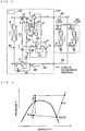
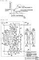
- Fig. 17 is a refrigerant circuit diagram during a cooling operation of an air-conditioning apparatus according to Embodiment 3.
- a refrigerant heat exchanger 14 is provided to exchange heat between the refrigerant (the refrigerant that passes through a first bypass valve 10 and returns to the first compressor 1) that is bypassed to an inlet piping of an accumulator 11 from a discharge piping 23 of an expander 8 and the refrigerant (the refrigerant that is bypassed from a main radiator 4b to an indoor heat exchanger 102 that functions as an evaporator) that has passed through a bypass valve 5.
- the refrigerant heat exchanger 14 has a channel through which the refrigerant that has passed through the bypass valve 5 passes, and another channel through which the refrigerant passes after passing through the bypass valve 10 of a bypass piping 24 that bypasses from the discharge piping 23 of the expander 8 to the inlet piping of the accumulator 11.
- An inflow port of the channel is connected to the bypass valve 5 and a second four-way valve 6, and an outflow port of the channel is connected to expansion valves 31a and 31b.
- An inflow port of the other channel is connected to the bypass valve 10, and an outflow port of the other channel is connected to the accumulator 11.
- bypass piping 46 having one end connected to a suction piping 21 of the second compressor 2, and the other end connected to the inlet piping of the accumulator 11 is provided, and a bypass valve 15 is provided in the bypass piping 46.
- the bypass valve 15 is opened during the operation of preventing the expander 8 from overexpanding.
- the outdoor heat exchanger 4 is divided into two heat exchangers 4a and 4b.
- the heat exchanger 4a functions as an intercooler
- the heat exchanger 4b functions as a main radiator.
- both the heat exchangers 4a and 4b function as evaporators.
- opening/closing valves 12a, 12b, 13a, 13b, and 13c are provided.
- the opening/closing valves 12a and 12b are opened, and the opening/closing valves 13a, 13b, and 13c are closed.
- the refrigerant discharged from the first compressor 1 flows into the second compressor 2 after passing through the intercooler 4a.
- the refrigerant is first cooled.
- the refrigerant discharged from the second compressor 2 flows into the expander 8 after passing through the main radiator 4b.
- the opening/closing valves 12a and 12b is closed, and the opening/closing valves 13a, 13b, and 13c are opened. Thereby, the refrigerant discharged from the first compressor 1 is sucked into the second compressor 2. Additionally, the refrigerant that has flowed into the outdoor heat exchanger 4 is directed to the first compressor 1 after flowing in parallel with each of the heat exchanger 4a and the heat exchanger 4b.
- the heat exchanger 4a and the heat exchanger 4b function as evaporators during a heating operation as described above.
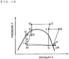
- Embodiment 3 the operation during a cooling operation of the air-conditioning apparatus according to Embodiment 3 will be described referring to the refrigerant circuit diagram of Fig. 17 and the P-h diagram of Fig. 18 .
- Embodiment 1 the operation of the air-conditioning apparatus in a state where the bypass valve 10 is opened as the operation of preventing the expander 8 from overexpanding will be described.
- Embodiment 3 is the same as Embodiment 1 in that the refrigerant does not flow to the channel between Point F and Point G in Fig. 17 due to a check valve 9 when the bypass valve 10 is opened.
- a gas refrigerant sucked into the first compressor 1 is compressed and is discharged as a medium-pressure and high-temperature supercritical (or gas) refrigerant (from State A to State B).
- the refrigerant that has come out of the first compressor 1 flows to the intercooler 4a through a piping 43. While the medium-pressure and high-temperature refrigerant is passing through the inside of the intercooler 4a, the refrigerant is cooled by the heat exchange with outdoor air and flows out as a medium-pressure and medium-temperature supercritical (or gas) refrigerant (from State B to State L), and is sucked into the second compressor 2 through a piping 42, and the suction piping 21 of the second compressor 2.
- a medium-pressure and medium-temperature supercritical (or gas) refrigerant from State B to State L
- the refrigerant sucked into the second compressor 2 is further compressed and is discharged as a high-pressure and high-temperature supercritical (or gas) refrigerant (from State L to State C).
- the refrigerant that has come out of the second compressor 2 flows to the main radiator 4b through a first four-way valve 3. While the high-pressure and high-temperature refrigerant passes through the inside of the main radiator 4b, the refrigerant is cooled by exchanging heat with the outdoor air, and flows out as a high-pressure and low-temperature supercritical (or liquid) refrigerant (from State C to State D).
- the refrigerant that has come out of the main radiator 4b branches into a path directed to the second four-way valve 6 and a path directed to the bypass valve 5.
- the refrigerant that has passed through the second four-way valve 6 passes through a pre-expansion valve 7 (from State D to State E), is sucked into and decompressed to Low Pressure by the expander 8, and becomes low in dryness (from State E to State F).
- power is generated with the decompression of the refrigerant, and this power is recovered by a drive shaft 52, is transferred to the second compressor 2, and is used for compression of the refrigerant by the second compressor 2.
- the refrigerant discharged from the expander 8 flows into the bypass piping 24 from the discharge piping 23 of the expander 8, is decompressed in the bypass valve 10 (from State F to State M), and flows into the refrigerant heat exchanger 14 from the inflow port of the other channel of the refrigerant heat exchanger 14.
- the refrigerant that has flowed out of the outdoor heat exchanger 4 and flowed into a bypass piping 25 is decompressed by the bypass valve 5 (from State F to State G), and flows into the refrigerant heat exchanger 14 from the inflow port of the one channel of the refrigerant heat exchanger 14.
- the refrigerant in a state M flowing into the channel "on the other side” has a lower pressure and a lower temperature than the refrigerant in a state G flowing into the channel "on one side”.
- the refrigerant "on the other side” that has flowed into the refrigerant heat exchanger 14 through the bypass valve 10 is heated by exchanging heat with the refrigerant "on one side", and becomes higher in dryness (from State M to State N).
- the refrigerant "on one side” that has flowed into the refrigerant heat exchanger 14 through the bypass valve 5 is cooled by exchanging heat with the refrigerant "on the other side", and becomes low in dryness (from State G to State H).
- the refrigerant "on one side" that has come out of the refrigerant heat exchanger 14 comes out of the outdoor unit 101, passes through the liquid pipe 28, flows into indoor units 102a and 102b, and flows into the expansion valves 31a and 31b. In the expansion valves 31a and 31b, the refrigerant is further decompressed (from State H to a state I).
- the refrigerant that has come out of the expansion valves 31a and 31b removes heat from the indoor air and evaporates in indoor heat exchangers 32a and 32b, and becomes high in dryness in a low-pressure state (from State I to State J).
- the refrigerant that has come out of the indoor heat exchangers 32a and 32b comes out of the indoor units 102a and 102b, passes through the gas pipe 29, flows into the outdoor unit 101, and passes through the first four-way valve 3. Then, the refrigerant "on the other side” that has come out of the refrigerant heat exchanger 14 and the refrigerant that has passed through the bypass valve 15 merge, and flow into the accumulator 11, and are again sucked into the first compressor 1.
- the bypass valve 10 is opened during the operation of preventing the expander 8 from overexpanding.
- the bypass valve 15 is also opened so as to flow the refrigerant to the bypass piping 46.
- the discharge pressure of the second compressor 2 can be adjusted by opening the bypass valve 15. For this reason, when the flow rate of the refrigerant that passes through the expander 8 decreases and the rotational frequency of the expander 8 and the second compressor 2 decrease, the bypass valve 15 can be opened to prevent the discharge pressure of the second compressor 2 from becoming too high.
- the opening degree of the bypass valve 15 is adjusted, for example, on the basis of the pressure P(81), detected by the pressure sensor 81, which is the discharge pressure of the second compressor 2.
- the medium-pressure and high-temperature refrigerant discharged from the first compressor 1 is first cooled in the intercooler 4a, and is then further compressed in the second compressor 2. For this reason, compared to when a medium-pressure refrigerant is compressed to High Pressure in the second compressor 2 without being cooled, the power required for a certain compression ratio is smaller in the compression process of the second compressor 2. If the power recovered in the expander 8 is the same, since the amount of a pressure rise in the second compressor 2 can be increased, the amount of pressure rise of the first compressor 1 becomes small. That is, the electric power consumed in the first compressor 1 can be reduced, and the air-conditioning apparatus can further be energy efficient.
- heat can be rejected with improved heat transfer capacity because the intercooler 4a and the main radiator 4b are connected in series during a cooling operation, and pressure loss can be reduced because the intercooler and the main radiator are connected in parallel during a heating operation.
- the bypass valve 5 and the bypass valve 15 are adjusted during the start of the air-conditioning apparatus. For this reason, even when the refrigerant flow rates of the second compressor 2 and the expander 8 do not match each other and rotation becomes unstable during the start of the air-conditioning apparatus, the refrigerants that flow through the second compressor 2 and expander 8 may be bypassed appropriately during the start.
- the refrigerant that flows through the bypass piping 24, and refrigerants that flow into the indoor heat exchangers 32a and 32b exchange heat in the refrigerant heat exchanger 14. For this reason, refrigerating effect can be increased in the indoor heat exchangers 32a and 32b. Moreover, since the degree of dryness of the refrigerant that flows through the bypass piping 24 can be further increased, the amount of a liquid refrigerant that flows into the accumulator 11 can be made smaller.
- the refrigerant that flows into the outdoor heat exchanger 4 during a heating operation is cooled by the refrigerant heat exchanger 14 before the refrigerant flows into the outdoor heat exchanger 4, the degree of dryness of the refrigerant that flows into the outdoor heat exchanger 4 can be made smaller. For this reason, the pressure loss of the refrigerant in the outdoor heat exchanger 4 can be made smaller, or the distribution capacity of the refrigerant in the outdoor heat exchanger 4 can be further improved.
- the opening degree of the bypass valve 15 is adjusted and accordingly the discharge pressure of the second compressor 2 is adjusted. For this reason, when the flow rate of the refrigerant that passes through the expander 8 decreases and the rotational frequency of the expander 8 and second compressor 2 decrease, the discharge pressure of the second compressor 2 can be prevented from becoming too high.
- the bypass valve 15 and the bypass piping 46 may be provided in the refrigerant circuit of Embodiment 1 shown in Fig. 1 in which the same advantages are also obtained.
- the air-conditioning apparatus may be configured to perform intercooling even during a heating operation.
- the air-conditioning apparatus may be configured to bypass the refrigerant discharged from the first compressor 1.
- the second compressor 2 is provided on the downstream side of the first compressor 1.
- the second compressor 2 may be provided on the upstream side of the first compressor 1.
Description
- The present invention relates to a refrigeration cycle apparatus using a refrigerant, such as a fluid that is brought into a supercritical state, and particularly, to a refrigeration cycle apparatus equipped with an expander that recovers the fluid energy as power during its expansion process.
- In the related art, as a refrigeration cycle apparatus equipped with an expander that recovers the fluid energy as power during its expansion process, for example, there is a refrigeration cycle apparatus equipped with a first compressor that is driven by an electric motor to compress refrigerant, a radiator that rejects the heat of the refrigerant compressed by the first compressor, an expander that decompresses the refrigerant that has passed through the radiator, an evaporator in which the refrigerant decompressed by the expander evaporates, and a second compressor that is driven by the expansion power recovered in the expander and has a discharge side connected to a suction side of the first compressor (for example, refer to Patent Literature 1).
- Additionally, there is a refrigeration cycle apparatus equipped with a first compressor, a radiator that rejects the heat of refrigerant compressed by the first compressor, an expander that decompresses the refrigerant that has passed through the radiator, an evaporator in which the refrigerant decompressed by the expander evaporates, and a supercharger (a second compressor) that raises the pressure of the refrigerant evaporated in the evaporator and supplies the refrigerant to the first compressor (for example, refer to Patent Literature 2).
-
- Patent Literature 1:
JP-2006-125790A Fig. 4 , Abstract) - Patent Literature 2:
JP-2009-79850A Fig. 2 , Abstract) - In the refrigeration cycle apparatus of the related art described in the
above Patent Literature 1, a supercooling heat exchanger that supercools the refrigerant that flows out of the expander is provided on the discharge side of the expander, and in the supercooling heat exchanger, among a mainstream portion and a substream portion through which the refrigerant passes, one end of the substream portion is connected to a bypass piping bypassed from a piping that connects the expander and the mainstream portion via a supercooling expansion valve, and the other end of the substream portion is connected to a suction side of the first compressor. The efficiency of a refrigeration cycle can be improved by supercooling the refrigerant that flows out of the expander with the supercooling heat exchanger. However, when the supercooling expansion valve is opened in this bypass circuit, the pressure on the discharge side of the expander cannot be made low, and when the refrigerant bypassing an outdoor heat exchanger or an indoor heat exchanger functioning as a radiator or an evaporator increases, the discharge pressure of the expander may rise instead. - Additionally, in the refrigeration cycle apparatus of the related art described in the
above Patent Literature 2, a bypass path is provided to bypass the refrigerant to a suction side of the first compressor from a discharge side of the expander, and an opening/closing valve is provided in the bypass path. When the first compressor starts, the refrigerant in the refrigerant circuit from an outlet of the expander to a suction port of the second compressor is supplied to the compressor not through the second compressor but through the bypass path. Thereby, shortage of supply of the refrigerant to the compressor at the time of start is prevented and the pressure differential between the suction side and discharge side of the expander is increased, thereby solving poor starting of the expander. However, since the opening/closing valve is closed with the detection of the start of the second compressor, after the second compressor has been started, the rotation of the second compressor and the expander are disadvantageously unstable until the discharge pressure of the expander reaches an appropriate expansion pressure. - The invention has been made to solve the above problem, and an object thereof is to provide a refrigeration cycle apparatus that can stably recover power with an expander.
- A refrigeration cycle apparatus according to the invention is defined in
claim 1. It includes: a refrigeration cycle formed by sequentially connecting with pipes a first compressor that compresses a refrigerant, a radiator that rejects the heat of the refrigerant compressed by the first compressor, an expander that expands the refrigerant that has passed through the radiator and recovers power from the refrigerant, and an evaporator that evaporates the refrigerant expanded by the expander; a first bypass piping having one end connected to a discharge piping of the expander and the other end connected to a piping between the first compressor and the evaporator; physical quantity detecting means that detects a physical quantity of the refrigerant to be sucked into the expander; a first bypass valve provided in the first bypass piping to control the flow rate of the refrigerant; and control means that controls an opening degree of the first bypass valve, in which the control means determines an appropriate discharge pressure of the expander on the basis of the physical quantity detected by the physical quantity detecting means and opens the first bypass valve when an pressure at which the expander discharges the refrigerant is higher than the determined appropriate discharge pressure. - According to the refrigeration cycle apparatus relating to the invention, when the discharge pressure of the expander is higher than the appropriate discharge pressure due to the operating state of the refrigeration cycle apparatus, the first bypass valve is opened to bypass the refrigerant from the discharge piping of the expander to the suction side of the first compressor. Thus, the discharge pressure of the expander can be made low. This can prevent the expander from overexpanding and can stabilize the rotation of the expander.
-
-
Fig. 1 is a refrigerant circuit diagram during a cooling operation of an air-conditioning apparatus equipped with a refrigeration cycle apparatus according toEmbodiment 1 of the invention. -
Fig. 2 is a P-h diagram showing the cooling operation of the air-conditioning apparatus according toEmbodiment 1 of the invention ofFig. 1 . -
Fig. 3 is a refrigerant circuit diagram during a heating operation of the air-conditioning apparatus according toEmbodiment 1 of the invention. -
Fig. 4 is a P-h diagram showing the heating operation of the air-conditioning apparatus according toEmbodiment 1 of the invention. -
Fig. 5 is a cross-sectional view of a scroll expander integral with a second compressor of the air-conditioning apparatus according toEmbodiment 1 of the invention. -
Fig. 6 is a view schematically showing the distribution of a thrust load that acts on second compressor side and the distribution of a thrust load that acts on expander side at design points of the second compressor and the expander of the air-conditioning apparatus according toEmbodiment 1 of the invention. -
Fig. 7 is a P-h diagram showing a cooling operation when the expander of the air-conditioning apparatus according toEmbodiment 1 of the invention overexpands. -
Fig. 8 is a P-v diagram when the expander of the air-conditioning apparatus according toEmbodiment 1 of the invention undergoes an appropriate expansion process. -
Fig. 9 is a P-v diagram when the expander of the air-conditioning apparatus according toEmbodiment 1 of the invention undergoes an overexpansion process. -
Fig. 10 is a view schematically showing the distribution of a thrust load that acts on the second compressor side and the distribution of a thrust load that acts on the expander side, when the expander of the air-conditioning apparatus according toEmbodiment 1 of the invention undergoes the overexpansion process. -
Fig. 11 is a flowchart showing the operation of preventing the expander of the air-conditioning apparatus according toEmbodiment 1 of the invention from overexpanding. -
Fig. 12 is a view showing an example of the relationship of an appropriate discharge pressure Po to the suction pressure and suction temperature of the expander according toEmbodiment 1 of the invention. -
Fig. 13 is a P-h diagram showing an example of the operating state during a cooling operation when the operation of preventing the expander according toEmbodiment 1 of the invention from overexpanding is performed. -
Fig. 14 is a P-v diagram showing an expansion process when the suction pressure of the expander according toEmbodiment 1 of the invention becomes low. -
Fig. 15 is a flowchart showing the operation of preventing an expander of an air-conditioning apparatus equipped with a refrigeration cycle apparatus according toEmbodiment 2 of the invention from overexpanding. -
Fig. 16 is a view showing changes in High Pressure and expander discharge pressure when the air-conditioning apparatus according toEmbodiment 2 of the invention starts. -
Fig. 17 is a refrigerant circuit diagram during a cooling operation of an air-conditioning apparatus equipped with a refrigeration cycle apparatus according toEmbodiment 3 of the invention. -
Fig. 18 is a P-h diagram showing the cooling operation of the air-conditioning apparatus according toEmbodiment 3 of the invention. -
Fig. 1 is a refrigerant circuit diagram during a cooling operation of an air-conditioning apparatus equipped with a refrigeration cycle apparatus according toEmbodiment 1 of the invention.Fig. 2 is a refrigerant circuit diagram during the cooling operation of the air-conditioning apparatus ofFig. 1 . - The air-conditioning apparatus of
Fig. 1 is equipped with a refrigeration cycle apparatus that is formed by sequentially connecting by means of piping afirst compressor 1 that is driven by an electric motor to compress a refrigerant, asecond compressor 2, an outdoor heat exchanger 4, anexpander 8 that expands the refrigerant that passes therethrough and recovers power from the refrigerant, and anindoor heat exchanger 32. Thesecond compressor 2 and theexpander 8 are coupled together with adrive shaft 52, and thesecond compressor 2 is driven via thedrive shaft 52 by the power recovered by theexpander 8. - The outdoor heat exchanger 4 becomes a radiator in which an internal refrigerant rejects heat during a cooling operation, and becomes an evaporator in which the internal refrigerant evaporates during a heating operation. Additionally, the
indoor heat exchanger 32 becomes an evaporator in which the internal refrigerant evaporates during a cooling operation, and becomes a radiator in which the internal refrigerant rejects heat during a heating operation. - Additionally, this air-conditioning apparatus is equipped with a
bypass piping 24 that bypasses the refrigerant to aninlet piping 27 of anaccumulator 11 from adischarge piping 23 of theexpander 8, and abypass valve 10 that adjusts the flow rate of the refrigerant that flows through thebypass piping 24. - Additionally, in this air-conditioning apparatus, carbon dioxide is used as the refrigerant, and as compared to conventional chlorofluorocarbon refrigerants, this carbon dioxide has zero ozone depletion potential and a low global warming potential.
- In
Embodiment 1, thefirst compressor 1, thesecond compressor 2, a first four-way valve 3 that is a refrigerant flow switching device, the outdoor heat exchanger 4, a second four-way valve 6 that is a refrigerant flow switching device, apre-expansion valve 7, theexpander 8, abypass valve 5, thebypass valve 10, and theaccumulator 11 are accommodated in anoutdoor unit 101. Anexpansion valve 31a and anindoor heat exchanger 32a are accommodated in anindoor unit 102a, and anexpansion valve 31b and anindoor heat exchanger 32b are accommodated in anindoor unit 102b. Acontrol device 103 that controls the overall control of the air-conditioning apparatus is also accommodated in theoutdoor unit 101. In addition, although the number of the indoor units 102 (indoor heat exchangers 32) is set to two in Embodiment 1, the number of theindoor units 102 is arbitrary. Additionally, theoutdoor unit 101 and theindoor units liquid pipe 28 and agas pipe 29. - The
first compressor 1 is driven by an electric motor (not shown) to compress and discharge the sucked-in refrigerant. Thesecond compressor 2 and theexpander 8 are accommodated in acontainer 51. Thesecond compressor 2 is connected to theexpander 8 via thedrive shaft 52, and power generated in theexpander 8 is recovered by thedrive shaft 52 and is transferred to thesecond compressor 2. Hence, thesecond compressor 2 sucks in the refrigerant discharged from thefirst compressor 1, and further compresses the refrigerant. - The first four-
way valve 3 is provided in a refrigerant channel between the outdoor heat exchanger 4, thesecond compressor 2, theindoor heat exchanger 32, and theaccumulator 11. Additionally, the second four-way valve 6 is provided in a refrigerant channel between the outdoor heat exchanger 4, theexpander 8, and theindoor heat exchanger 32. The first four-way valve 3 and the second four-way valve 6 are switched corresponding to the cooling or heating operation mode, on the basis of an instruction from thecontrol device 103, and switch the refrigerant path. - During a cooling operation, the refrigerant flows sequentially from the
second compressor 2 to the outdoor heat exchanger 4, theexpander 8, theindoor heat exchanger 32, theaccumulator 11, and thefirst compressor 1, and returns to thesecond compressor 2. - During a heating operation, the refrigerant flows sequentially from the
second compressor 2 to theindoor heat exchanger 32, theexpander 8, the outdoor heat exchanger 4, theaccumulator 11, and thefirst compressor 1, and returns to thesecond compressor 2. - The flow direction of the refrigerant that passes through the
expander 8 and thesecond compressor 2 are made to be the same irrespective of the cooling operation and the heating operation by the first four-way valve 3 and second four-way valve 6. - The outdoor heat exchanger 4 has, for example, a heat transfer tube through which the refrigerant flows and fins (not shown) for increasing the heat transfer area between the refrigerant that flows through the heat transfer tube and outdoor air, and exchanges heat between the refrigerant and air (outdoor air). For example, the outdoor heat exchanger functions as an evaporator during a heating operation, and evaporates the refrigerant and gasifies it. On the other hand, the outdoor heat exchanger functions as a condenser or a gas cooler (hereinafter referred to as a condenser) during a cooling operation. Depending on circumstances, the outdoor heat exchanger does not gasify or liquefy the refrigerant completely, but brings the refrigerant into a two-phase mixture (gas-liquid two-phase refrigerant) state of liquid and gas. The
accumulator 11 functions to reserve excess refrigerant in a refrigeration cycle or to prevent thefirst compressor 1 being damaged by return of liquid refrigerant to thefirst compressor 1 in large quantities. - A
refrigerant channel 22 between the second four-way valve 6 and an inlet of theexpander 8 is provided with thepre-expansion valve 7 that adjusts the flow rate of the refrigerant that passes through theexpander 8. Arefrigerant channel 23 between an outlet of theexpander 8 and the second four-way valve 6 is provided with a check valve 9 that arranges the direction in which the refrigerant flows to be one direction. A refrigerant channel between the outdoor heat exchanger 4 and theindoor heat exchanger 32 is provided with a bypass piping 25 that bypasses the second four-way valve 6, thepre-expansion valve 7, theexpander 8, and the check valve 9, and thebypass valve 5 that adjusts the flow rate of the refrigerant that passes through thebypass piping 25. By adjusting thepre-expansion valve 7 and thebypass valve 5, the flow rate of the refrigerant that passes through the expander can be adjusted to control the pressure on a high-pressure side, and maintain a refrigeration cycle in a highly efficient state. It should be noted that the pressure on the high-pressure side may be controlled by other methods, without being limited to the adjustment of thepre-expansion valve 7 and thebypass valve 5. - The bypass piping 24 that bypasses the
expansion valve 31 and theindoor heat exchanger 32, and thebypass valve 10 that adjusts the flow rate of the refrigerant that passes through the bypass piping 24 are provided between the refrigerant outlet of theexpander 8 and the refrigerant inlet of theaccumulator 11. - A refrigerant outlet of the
second compressor 2 is provided with apressure sensor 81 that detects the pressure of the refrigerant that has come out of thesecond compressor 2, the refrigerant outlet of theexpander 8 is provided with apressure sensor 82 that detects the pressure of the refrigerant that has come out of theexpander 8, the refrigerant channel between the second four-way valve 6 andexpansion valve 31 is provided with apressure sensor 83 that detects the pressure of the refrigerant that flows into theexpansion valve 31 or the pressure of the refrigerant that has come out of theexpansion valve 31, a refrigerant inlet of thefirst compressor 1 is provided with apressure sensor 84 that detects the pressure of the refrigerant that flows into thefirst compressor 1, and the refrigerant inlet of theexpander 8 is provided with apressure sensor 85 that detects the pressure of the refrigerant that flows into theexpander 8. - In addition, the positions of the
pressure sensors second compressor 2, the pressure of the refrigerant that has come out of theexpander 8, the pressure of the refrigerant that flows into theexpansion valve 31 or the pressure of the refrigerant that has come out of theexpansion valve 31, the pressure of the refrigerant that flows into thefirst compressor 1, and the pressure of the refrigerant that flows into theexpander 8 can be respectively detected. Additionally, as long as pressure can be estimated, thepressure sensors - The refrigerant inlet of the
expander 8 is provided with atemperature sensor 91 that detects the temperature of the refrigerant that flows into theexpander 8 and the a piping between the outdoor heat exchanger 4, and the second four-way valve 6 and thebypass valve 5 is provided with atemperature sensor 92 that detects the temperature of the refrigerant that has come out of the outdoor heat exchanger 4 or the refrigerant that flows into the outdoor heat exchanger 4. It should be noted that the position of thetemperature sensors expander 8, and the temperature of the refrigerant that flows into the outdoor heat exchanger 4 or the refrigerant that has come out of the outdoor heat exchanger 4 can be respectively detected. - The
indoor heat exchanger 32 has, for example, a heat transfer tube through which the refrigerant flows and fins (not shown) for increasing the heat transfer area between the refrigerant that flows through the heat transfer tube and outdoor air, and exchanges heat between the refrigerant and air (outdoor air). For example, the indoor heat exchanger functions as an evaporator during a cooling operation, and evaporates the refrigerant and gasifies it. On the other hand, the indoor heat exchanger functions as a condenser or a gas cooler (hereinafter referred to as a condenser) during a heating operation. - The
expansion valve 31a is connected to theindoor heat exchanger 32a, and theexpansion valve 31 b is connected to theindoor heat exchanger 32b. Theexpansion valves indoor heat exchangers expander 8, theexpansion valves - Next, the operation during a cooling operation of the air-conditioning apparatus according to
Embodiment 1 will be described referring to the refrigerant circuit diagram ofFig. 1 and the P-h diagram ofFig. 2 . Note that symbols A to K ofFigs. 1 and 2 correspond to each other. In addition, in the drawings described later, the respective symbols in refrigerant circuits and corresponding P-h diagrams shall also correspond to the above. Now, high/low pressures in the refrigeration cycle or the like are not based on the relationship with a reference pressure; the high/low pressures shall be an expression of relative pressures resulting from the compression by thefirst compressor 1 and thesecond compressor 2, the decompression by thebypass valve 5 or theexpander 8, or the like. Additionally, the same shall also be true for high /low temperatures. Furthermore, here, thebypass valve 10 shall be closed, and the refrigerant shall not flow through thebypass piping 24. - During a cooling operation, first, a low-pressure refrigerant sucked into the
first compressor 1 is compressed and becomes high in temperature and medium in pressure (from State A to State B). - The refrigerant discharged from the
first compressor 1 is sucked into thesecond compressor 2, and is further compressed so as to become high in temperature and high in pressure (from State B to State C). - The refrigerant discharged from the
second compressor 2 passes through the first four-way valve 3, and flows into the outdoor heat exchanger 4. - The refrigerant that has radiated heat and transferred heat to the outdoor air in the outdoor heat exchanger 4 becomes low in temperature and high in pressure (from State C to State D).
- The refrigerant that has come out of the outdoor heat exchanger 4 branches into a path directed to the second four-
way valve 6 and a path directed to thebypass valve 5. - The refrigerant that has passed through the second four-
way valve 6 passes through the pre-expansion valve 7 (from State D to State E), is sucked into and decompressed to Low Pressure by theexpander 8, and becomes low in dryness (from State E to State F). - At this time, in the
expander 8, power is generated with the decompression of the refrigerant, is recovered by thedrive shaft 52, is transferred to thesecond compressor 2, and is used to compress the refrigerant with thesecond compressor 2. - After the refrigerant discharged from the
expander 8 passes through the check valve 9 and the second four-way valve 6, the refrigerant flows toward thebypass valve 5 and merges with the refrigerant that has passed through the bypass piping 25 (from State F to State G), comes out of theoutdoor unit 101, and passes through theliquid pipe 28, flows into theindoor units expansion valves - The refrigerant is further decompressed in the
expansion valves - The refrigerant that has come out of the
expansion valves indoor heat exchangers - Thereby, the indoor air is cooled.
- A refrigerant that has come out of the
indoor heat exchangers indoor units gas pipe 29, flows into theoutdoor unit 101, passes through the first four-way valve 3, flows into theaccumulator 11, and is again sucked into thefirst compressor 1. - By repeating the above-described operation, the heat of the indoor air is transferred to the outdoor air, and the interior of a room is cooled.
- Next, the operation during a heating operation of the air-conditioning apparatus according to
Embodiment 1 will be described referring to the refrigerant circuit diagram ofFig. 3 and a P-h diagram ofFig. 4 . Note that, here, thebypass valve 10 shall be closed, and the refrigerant shall not flow through thebypass piping 24. - During a heating operation, first, a low-pressure refrigerant sucked into the
first compressor 1 is compressed, and becomes high in temperature and medium in pressure (from State A to State B). - The refrigerant discharged from the
first compressor 1 is sucked into thesecond compressor 2, and is further compressed so as to become high in temperature and high in pressure (from State B to State J). - The refrigerant discharged from the
second compressor 2 passes through the first four-way valve 3, and comes out of theoutdoor unit 101. - The refrigerant that has come out of the
outdoor unit 101 passes through thegas pipe 29, flows into theindoor units indoor heat exchangers 32a and 2b. The refrigerant that has rejected heat and transferred heat to indoor air in theindoor heat exchangers - The refrigerant that has come out of the
indoor heat exchangers expansion valves - The refrigerant that has come out of the
expansion valves indoor units liquid pipe 28, flows into theoutdoor unit 101, and branches into the path directed to the second four-way valve 6 and the path directed to thebypass valve 5. - The refrigerant that has passed through the second four-
way valve 6 passes through the pre-expansion valve 7 (from State G to State E), flows into and is decompressed to Low Pressure by theexpander 8, and becomes low in dryness (from State E to State F). At this time, in theexpander 8, power is generated with the decompression of the refrigerant, is recovered by thedrive shaft 52, is transferred to thesecond compressor 2, and is used to compress the refrigerant with thesecond compressor 2. - After the refrigerant that has come out of the
expander 8 passes through the check valve 9 and the second four-way valve 6, the refrigerant flows toward thebypass valve 5 and merges with the refrigerant that has passed through the bypass piping 25 (from State F to State D), and flows into the outdoor heat exchanger 4. - In the outdoor heat exchanger 4, the refrigerant removes heat from the outdoor air and evaporates, and becomes high in dryness while still low in pressure (from State D to State C).
- The refrigerant that has come out of the outdoor heat exchanger 4 passes through the first four-
way valve 3, flows into theaccumulator 11, and is again sucked into thefirst compressor 1. - By repeating the above-described operation, the heat of the outdoor air is transferred to the indoor air, and the interior of a room is heated.
- Next, the structure and operation of a
scroll expander 8 and asecond scroll compressor 2 as examples of thesecond compressor 2 and theexpander 8 will be described. Note that thesecond compressor 2 and theexpander 8 may be other positive displacement types without being limited to the scroll type. -
Fig. 5 is a cross-sectional view of thescroll expander 8 integral with thesecond compressor 2. Theexpander 8 that expands the refrigerant and recovers power is composed ofspiral teeth 67 of a fixedscroll 59 of the expander, andspiral teeth 65 on the bottom face of anorbiting scroll 57. Additionally, thesecond compressor 2 that compresses the refrigerant by the power recovered in theexpander 8 is composed ofspiral teeth 66 of a fixedscroll 58 of the compressor, andspiral teeth 64 on the top face of the orbitingscroll 57. That is, since thespiral teeth 65 of theexpander 8 and thespiral teeth 64 of thesecond compressor 2 are integrally formed back to back on two faces of a common base plate in theorbiting scroll 57, compression can take place on one side and expansion can take place on the other side, when the orbitingscroll 57 is driven. - A high-temperature and medium-pressure refrigerant discharged from the
first compressor 1 is sucked into asuction pipe 53 of thesecond compressor 2, and is introduced into the outer peripheral side of thesecond compressor 2 formed by thespiral teeth 66 of the fixedscroll 58 of the compressor, and thespiral teeth 64 of the orbitingscroll 57. Then, by the orbiting of the orbitingscroll 57, the refrigerant is gradually moved to the inner peripheral side in thesecond compressor 2 and is compressed to high temperature and High Pressure. The compressed refrigerant is discharged from adischarge pipe 54 of thesecond compressor 2. - On the other hand, a high-pressure refrigerant cooled in the outdoor heat exchanger 4 or the
indoor heat exchanger 32 is sucked into asuction pipe 55 of theexpander 8, and is introduced into the inner peripheral side of theexpander 8 formed by thespiral teeth 67 of the fixed scroll of the expander and thespiral teeth 65 of the orbitingscroll 57. Then, by the orbiting of the orbitingscroll 57, the refrigerant is gradually moved to the outer peripheral side in theexpander 8 and is expanded into Low Pressure. The expanded refrigerant is discharged from adischarge pipe 56 of theexpander 8. The expansion power of the refrigerant in theexpander 8 is recovered via thedrive shaft 52, is transferred to thesecond compressor 2, and is used as compression power. - The afore-mentioned mechanism constituted by the
second compressor 2 and theexpander 8 is accommodated in thecontainer 51. - Now, a thrust load (axial load) that acts on the
orbiting scroll 57 will be described.Fig. 6 schematically shows distribution of the thrust loads of thesecond compressor 2 and theexpander 8 that act on thesecond compressor 2 side and the expander side at design points of thesecond compressor 2. The thrust load that acts on thesecond compressor 2 side is force that presses the orbitingscroll 57 towards the fixedscroll 59 of theexpander 8. The thrust load that acts on theexpander 8 side is force that presses the orbitingscroll 57 towards the fixedscroll 58 of thesecond compressor 2. - Additionally, as shown in the scroll internal pressure distribution, the discharge pressure of the
second compressor 2 will be denoted as High Pressure, the suction pressure of thesecond compressor 2 will be denoted as Medium Pressure, and the discharge pressure of theexpander 8 will be denoted as Low Pressure. Now, the reference pressure of the pressing force will be the Low Pressure. - First, a thrust load that acts on the
second compressor 2 by the refrigerant compressed by thesecond compressor 2 will be obtained. The area in which theorbiting scroll 57 receives the load from the refrigerant compressed in thesecond compressor 2 is defined as Sc [mm2]. Supposing the mean value of Medium Pressure PM-Low Pressure PL [MPa], which is a difference between the pressure on the outer peripheral side of thesecond compressor 2 and the reference pressure, and High Pressure PH-Low Pressure PL [MPa], which is a difference between the pressure on the inner peripheral side and the reference pressure, acts on the area Sc, the thrust load Fthc [N] of thesecond compressor 2 may be obtained by Formula (1).
- Next, the thrust load that acts on the
expander 8 by the refrigerant that expands in theexpander 8 will be obtained. The area in which theorbiting scroll 57 receives the load from the refrigerant that expands in theexpander 8 is defined as Se [mm2]. Since the outer peripheral side of theexpander 8 is the same Low Pressure as the reference pressure, supposing 1/2 of High Pressure PH-Low Pressure PL [MPa], which is a difference between the pressure on the inner peripheral side and the reference pressure, acts on the area Se, the thrust load Fthe [N] of theexpander 8 may be obtained by Formula (2).
- Supposing the direction of the thrust load Fthc that is going to press the orbiting
scroll 57 towards the fixedscroll 59 of theexpander 8 is positive, Fthe and Fthc become loads in opposite directions, and the thrust load Fth that acts on theorbiting scroll 57 may be Formula (3).
- When the thrust load Fth is excessively large,
teeth tips 72 of thespiral teeth 65 of the orbitingscroll 57 are pressed against the fixedscroll 59 of the expander and the friction between the orbitingscroll 57 and the fixedscroll 59 of the expander becomes large. As a result, the power to be recovered in theexpander 8 will be lost as friction loss. - When the mean values of the pressure distribution are compared with Formulas (1) and (2), it is clear that the following formula is satisfied.

Fig. 6 , Fth is made small such that theteeth tips 72 of thespiral teeth 65 of the orbitingscroll 57 are moderately pressed against the fixedscroll 59 of the expander, thereby making the friction between the orbitingscroll 57 and the fixedscroll 59 of the expander small. - During the operation of the air-conditioning apparatus, when the number of operating
indoor units 102 changes and the load transitionally fluctuates, the balance of the flow rates between theexpander 8 and thesecond compressor 2 may be disrupted, and the rotation of thesecond compressor 2 and theexpander 8 may become unstable. For example, as in the above-described case, the transitional decrease of the rotational frequency of thesecond compressor 2 and theexpander 8 act as resistance against circulation of the refrigerant and the High Pressure will rise. - Now, an operating state during a cooling operation of the air-conditioning apparatus when the High Pressure of the air-conditioning apparatus has risen transitionally is shown in a P-h diagram of
Fig. 7 . The discharge pressure (state C2) of thesecond compressor 2 and the discharge pressure (state D2) of the outdoor heat exchanger 4 rise. - Now, changes of pressure and volume during the expansion process of the
expander 8 will be described.Fig. 8 is a P-v diagram during an appropriate expansion process in which the outlet of theexpander 8 is brought into a state F, andFig. 9 is a P-v diagram during an overexpansion process in which the outlet of theexpander 8 is brought into a state F2. In the appropriate expansion process ofFig. 8 , the refrigerant is sucked in the state of pressure PH and volume Vei and is separated, by thespiral teeth 67 of the fixed scroll of the expander and thespiral teeth 65 of the orbitingscroll 57, and the separated refrigerant is decompressed while volume V increases. Then, when the volume V, separated by thespiral teeth 67 of the fixed scroll of the expander and thespiral teeth 65 of the orbitingscroll 57, becomes Vo that is its maximum volume, the expansion is completed, the pressure becomes Po. Po is a state in which the pressure is the lowest inside the expander. Po is the pressure obtained by the suction pressure PH of theexpander 8 and the expansion volume ratio Vi/Vo of theexpander 8, supposing that adiabatic expansion occurs inside theexpander 8. After the volume V becomes Vo, the refrigerant, separated by thespiral teeth 67 of the fixedscroll 59 of the expander and thespiral teeth 65 of the orbitingscroll 57, passes through thedischarge pipe 56 of theexpander 8, and is opened to Low Pressure PL. In the design points of the expander, the pressure Po at which expansion ends and the Low Pressure PL are almost equal. - On the other hand, during the overexpansion process in
Fig. 9 , the discharge pressure PL2 of theexpander 8 is higher than Po2 (appropriate discharge pressure) at which the pressure becomes the lowest during the expansion process of theexpander 8. During the overexpansion process ofFig. 9 , when the refrigerant, separated by thespiral teeth 67 of the fixedscroll 59 of the expander and thespiral teeth 65 of the orbitingscroll 57, is opened to thedischarge pipe 56 of theexpander 8 from Po2 at which the pressure becomes the lowest, the pressure rises up to the Low Pressure PL2. As mentioned above, the discharge pressure PL2 of theexpander 8 being higher than the appropriate discharge pressure Po2 is referred to as overexpansion. In order to prevent the overexpansion, the operation of appropriately reducing the discharge pressure of theexpander 8 may be performed such that the discharge pressure of theexpander 8 does not become higher than the appropriate discharge pressure. -
Fig. 10 schematically shows the distribution of thrust loads of thesecond compressor 2 and theexpander 8 that act on thesecond compressor 2 side and theexpander 8 side, when the High Pressure is PH2, the Medium Pressure is PM2, and the Low Pressure is PL2. At this time, a thrust load Fthc2 [N] that acts on thesecond compressor 2 side of the orbitingscroll 57 may be obtained by Formula (5), in the same way as Formula (1).
- However, the pressure of the outer periphery of the orbiting
scroll 57 on theexpander 8 side is the pressure Po2 at which expansion ends, which is lower than the Low Pressure PL2. That is, since force in an opposite direction to the inner peripheral side acts on the outer peripheral side of the orbitingscroll 57, a thrust load Fthe2 that acts on thespiral teeth 65 of the orbitingscroll 57 is expressed by Inequality (6), which is smaller than that obtained by Formula (2).
- Hence, even if the thrust load Fth is designed so as to be small by Formula (3), when an overexpansion process occurs on the
expander 8 side as shown inFigs. 9 and 10 , Fthc2 becomes larger than Fthe2 from the design point. As a result, the force with which theorbiting scroll 57 is pressed against the fixedscroll 59 of the expander increases. - When the force with which the
orbiting scroll 57 is pressed against the fixedscroll 59 of the expander increases, the friction between the orbitingscroll 57 and the fixedscroll 59 of the expander increases, which acts as resistance while the orbitingscroll 57 is orbiting, and accordingly expansion energy will be lost as friction loss. Additionally, if the friction becomes excessively large, the rotational frequency will decrease. - When the expansion process of the
expander 8 becomes an overexpansion process, since the refrigerant is compressed from the pressure Po2, at which expansion ends, until the refrigerant is opened to the Low Pressure PL2, the recovered power in theexpander 8 decreases correspondingly, and the driving force of thesecond compressor 2 decreases. Then, the rotational frequency of thesecond compressor 2 and theexpander 8 further decreases. - As described above, if the rotational frequency of the
second compressor 2 and theexpander 8 is decreased, thesecond compressor 2 andexpander 8 will act as resistance when the refrigerant circulates. Therefore, this causes a problem in that the High Pressure PH of the air-conditioning apparatus rises excessively. - Thus, in the air-conditioning apparatus according to
Embodiment 1, which is a refrigeration cycle apparatus, the discharge pressure of theexpander 8 is reduced by the following method, preventing overexpansion during the expansion process in theexpander 8. Specifically, the bypass piping 24 that bypasses the refrigerant from the discharge piping 23 of theexpander 8 to the inlet piping 27 of theaccumulator 11 is provided, and thebypass valve 10 that adjusts the bypass amount of the refrigerant to the bypass piping 24 is provided. As above, by connecting the discharge side of theexpander 8 to the suction side of thefirst compressor 1 that has the lowest pressure within the refrigeration cycle, the discharge pressure of theexpander 8 can be reduced, and further, overexpantion can be prevented during the expansion process in theexpander 8. - Moreover, the check valve 9 is provided further downstream than a connection port of the bypass piping 24 in the discharge piping 23 of the
expander 8. As is clear fromFig. 2 , between the state F of the refrigerant on the inlet side of the check valve 9 and the state G of the refrigerant on the outlet side, the state G is higher in pressure. Although the refrigerant flows to a lower pressure side from a higher pressure side, this is prevented by the check valve 9. That is, the check valve 9 prevents the refrigerant that has passed through the bypass piping 25 from flowing from Point G to Point F inFig. 1 , from passing through the bypass piping 24, and from flowing into theaccumulator 11. - By virtue of the above-described configuration, the discharge pressure of the
expander 8 can be made low even if the air-conditioning apparatus is operating in a state in which the discharge pressure of theexpander 8 becomes high. - Next, the operation of preventing the
expander 8 from overexpanding in the air-conditioning apparatus according toEmbodiment 1 will be described.Fig. 11 is a flowchart showing the operation of preventing the expander from overexpanding, in the air-conditioning apparatus according toEmbodiment 1. It should be noted that, in the following, the pressure P detected by a certain pressure sensor may be, using the symbol of the pressure sensor, designated as P(symbol) (for example, P(83) in the case of the pressure sensor 83). - The air-conditioning apparatus periodically checks the operation of the
expander 8 during regular control, such as a usual cooling operation and heating operation, and operates to prevent theexpander 8 from overexpanding. That is, thecontrol device 103 determines whether or not a predetermined time period has elapsed during regular control (Step S101). After the predetermined time period has elapsed, the value of the pressure P(82) detected by thepressure sensor 82 is determined whether it is higher than the discharge pressure (appropriate discharge pressure) Po of theexpander 8 when undergoing appropriate expansion (Step S102). This appropriate discharge pressure Po, as described above, is determined from the present suction pressure and suction temperature of theexpander 8, and the relational data, which is stored in advance in thecontrol device 103, between the suction temperature and the appropriate discharge pressure Po of each suction pressure of theexpander 8. - The
control device 103 proceeds to Step S104 when it is determined in Step S102 that P(82) is higher than Po. In Step S104, thecontrol device 103 increases an opening degree L10 of thebypass valve 10 provided in the bypass piping 24 by a preset amount ΔL, thereby increasing the flow rate of the refrigerant that flows to the bypass piping 24 (Step S103). As above, by opening thebypass valve 10 and communicating the discharge side of theexpander 8 and the suction side of theaccumulator 11 that is the lowest in pressure in the refrigeration cycle, passing the refrigerant discharged from theexpander 8 to the bypass piping 24 side, decompressing the refrigerant with thebypass valve 10, and then sucking the refrigerant into theaccumulator 11, the discharge pressure P(82) of theexpander 8 can be lowered. - Then, a
control device 102 ends the operation preventing overexpansion by closing thebypass valve 10 when it is determined in Step S103 that P(82) has become lower than Po. - Now, an example of the relationship between the suction temperature and the appropriate discharge pressure Po of each suction pressure of the
expander 8 is shown inFig. 12. Fig. 12 shows the relationship between the suction pressure and the appropriate discharge pressure when the suction pressure is 10 MPa, 9 MPa, and 8 MPa. A specific suction volume is determined from the suction pressure and suction temperature of theexpander 8. Additionally, since the relationship between the suction volume Vi and discharge volume Vo of theexpander 8 is constant, a specific volume when an expansion process is completed is determined from the specific suction volume of theexpander 8. The appropriate discharge pressure Po can be approximately calculated from the specific volume. Hence, the appropriate discharge pressure Po according to the suction pressure and suction temperature of theexpander 8 can be approximately estimated from the pressure detected by thepressure sensor 85, which is the suction pressure of theexpander 8, the temperature detected by thetemperature sensor 91, which is the suction temperature, and the relationship diagram shown inFig. 12 , which is stored in advance by thecontrol device 103. - Now, the operating state of the air-conditioning apparatus during a cooling operation when the aforementioned control of the flowchart in
Fig 11 for preventing theexpander 8 from overexpanding is performed will be described using a P-h diagram ofFig. 13 . - The refrigerant that has come out of the outdoor heat exchanger 4 branches into a path directed to the second four-
way valve 6 and a path directed to thebypass valve 5. - The refrigerant that has passed through the second four-
way valve 6 passes through the pre-expansion valve 7 (from State D3 to State E3), is sucked into and decompressed to Low Pressure by theexpander 8, and becomes low in dryness (from State E3 to State F3). - The refrigerant discharged from the
expander 8 flows into the bypass piping 24 from the discharge piping 23 of theexpander 8. Then, the refrigerant is further decompressed by the bypass valve 10 (from State F3 to State M). - On the other hand, the refrigerant (from State D3 to State G3) that has passed through the
bypass valve 5 and been decompressed comes out of theoutdoor unit 101, passes through theliquid pipe 28, flows into theindoor units expansion valves bypass valve 5 and State F3 of the refrigerant after passing through theexpander 8 are compared, the refrigerant pressure in State G3 is higher. Hence, although the refrigerant flows into the lower pressure side from the higher pressure side, since the check valve 9 is provided here as described above, the refrigerant does not flow to a channel between Point G and Point F ofFig. 1 , and all the refrigerant that has passed thebypass valve 5 flows to channels directed to theindoor units - In the
expansion valves - The refrigerant that has come out of the
expansion valves indoor heat exchangers - The refrigerant that has come out of the
indoor heat exchangers indoor units gas pipe 29, flows into theoutdoor unit 101, passes through the first four-way valve 3, merges with the refrigerant that has passed through thebypass valve 10, and flows into the accumulator 11 (State K). - The refrigerant that has come out of the
accumulator 11 is again sucked into thefirst compressor 1. - At this time, when the
bypass valve 10 is opened to flow the refrigerant discharged from theexpander 8 into theaccumulator 11, the suction pressure of thefirst compressor 1 may rise. In this case, when opening thebypass valve 10, the opening degree of thepre-expansion valve 7 may be made small to make the suction pressure of theexpander 8 low. Additionally, since the refrigerant that flows through theexpander 8 decreases when the opening degree of thepre-expansion valve 7 is made small, thebypass valve 5 may be opened in this case. - Additionally, since the check valve 9 is provided further downstream than a connection port of the bypass piping 24 in the discharge piping 23 of the
expander 8, the refrigerant that flows through the bypass piping 25 can be prevented from passing through the bypass piping 24 and flowing into theaccumulator 11. -
Fig. 14 is a P-v diagram showing an expansion process when the suction pressure of the expander is low. - As shown in
Fig. 14 , by decreasing the opening degree of thepre-expansion valve 7, the suction pressure Pi3 of theexpander 8 becomes lower than the suction pressure Pi2 of an inlet Point E2. Thereby, the degree of pressure change and volume change during the expansion process becomes small, and so, compared to when the suction pressure of theexpander 8 is high (Pi2), the difference between the suction pressure Pi of theexpander 8 and the appropriate discharge pressure Po becomes small. Thus, it will be easier to bring the discharge pressure PL3 of theexpander 8 close to the appropriate discharge pressure Po. - Additionally, the refrigerant discharged from the
expander 8 is a low-temperature and low-pressure gas-liquid two-phase refrigerant. If thefirst compressor 1 directly sucks in this refrigerant, thefirst compressor 1 performs liquid compression. As a result, the reliability of the compressor is impaired. Thus, in the air-conditioning apparatus according to the present embodiment, the refrigerant that flows through the bypass piping 24 is connected to the inlet piping 27 of theaccumulator 11. Therefore, the gas-liquid two-phase refrigerant can be reserved in theaccumulator 11 even if the gas-liquid two-phase refrigerant flows to thebypass piping 24. Therefore, thefirst compressor 1 can be prevented from performing liquid compression. - Additionally, according to
Embodiment 1, even if, due to the operating state of the air-conditioning apparatus, the expansion process of theexpander 8 transitionally becomes overexpanded during the expansion process of theexpander 8 increasing the thrust loads that act on thesecond compressor 2 and theexpander 8, and the driving force of thesecond compressor 2 further decreases destabilizing the rotation of thesecond compressor 2 and theexpander 8, by opening thebypass valve 10, the discharge pressure of theexpander 8 can be reliably lowered and prevent overexpansion. Therefore, the rotation of thesecond compressor 2 and theexpander 8 can be stabilized without the need of stopping the operation of the air-conditioning apparatus. - In the air-conditioning apparatus according to
Embodiment 1, since thebypass valve 10 is opened only when the discharge pressure of theexpander 8 is higher than the appropriate discharge pressure during regular control, the refrigerant discharged from theexpander 8 does not flow into theaccumulator 11 ineffectively. - As described above, when the discharge pressure of the
expander 8 becomes high during the cooling operation, the operation of preventing overexpansion is performed. The operation of preventing overexpansion is also effective during a heating operation, since the discharge pressure of theexpander 8 may become high, for example, when the pressure loss of the outdoor heat exchanger 4 is large during the heating operation. In the case of the heating operation, the saturation pressure of the refrigerant can be calculated from the temperature detected by thetemperature sensor 92, and can be adopted as the discharge pressure of thebypass valve 5. Further, the termination condition may be when the discharge pressure of thebypass valve 5 becomes lower than Po. - Additionally, according to
Embodiment 1, as shown inFig. 11 , the control of preventing overexpansion begins when the pressure P(82) detected by thepressure sensor 82 becomes higher than the appropriate discharge pressure Po of theexpander 8. However, the pressure at which the control starts may be set slightly higher than the appropriate discharge pressure Po of theexpander 8. This is because a little overexpansion of theexpander 8 will not have immediate, adverse influence on the air-conditioning apparatus. By setting the pressure to start the control slightly higher than the appropriate discharge pressure Po of theexpander 8, the air-conditioning apparatus can avoid frequent control of preventing overexpansion when there is some fluctuation in the pressure P(82). - Additionally, although the termination condition by which the control of preventing overexpansion is terminated is set to when the pressure P(83) detected by the
pressure sensor 83 becomes lower than the appropriate discharge pressure Po of theexpander 8 during a cooling operation, for example, the pressure at which the control is terminated may be slightly lower than the appropriate discharge pressure Po of theexpander 8. When during a heating operation, the termination condition by which the control of preventing overexpansion is terminated is set to when the discharge pressure of thebypass valve 5, which is a pressure calculated from the temperature detected by thetemperature sensor 92, becomes lower than the appropriate discharge pressure Po of theexpander 8. Also in this case, the actual pressure at which the control is terminated may be slightly lower than the appropriate discharge pressure Po of theexpander 8. As described above, by setting slight margins to the pressure at which the control of preventing overexpansion is started, and the pressure at which the control of preventing overexpansion is terminated, the control of preventing overexpansion can be prevented from being repeated frequently. - As described above, since the air-conditioning apparatus according to
Embodiment 1 opens thebypass valve 10 and prevents theexpander 8 from overexpanding when the discharge pressure of theexpander 8 is higher than the appropriate discharge pressure, the thrust loads of thesecond compressor 2 and theexpander 8 can be made small. Additionally, since the thrust loads of thesecond compressor 2 and theexpander 8 can be made small, and thereby, the driving force of thesecond compressor 2 is easily obtained, the rotational frequency of theexpander 8 can be stabilized. - Although the air-conditioning apparatus according to
Embodiment 1 determines the start of the operation of preventing the overexpansion of the expander 8 (increasing the opening degree of thebypass valve 10 by a predetermined amount ΔL) on the basis of the discharge pressure of theexpander 8, other physical quantities of the refrigerant correlated with the discharge pressure of theexpander 8 may be adopted. For example, since the discharge pressure of thesecond compressor 2 rises when the rotational frequency of thesecond compressor 2 and theexpander 8 decrease, the pressure P(81) detected by thepressure sensor 81 may be adopted as a determination factor. Additionally the rotational frequency of thesecond compressor 2 and theexpander 8 may be detected directly, and this rotational frequency may be adopted as a determination factor. - Additionally, in the air-conditioning apparatus according to
Embodiment 1, thesecond compressor 2 is provided in the refrigerant path between thefirst compressor 1 and the first four-way valve 3, and power is transferred to thesecond compressor 2 via thedrive shaft 52 from theexpander 8. As above, thesecond compressor 2 can use the power generated when the expander decompresses the refrigerant, and the efficiency of the air-conditioning apparatus can be improved. - Additionally, in the air-conditioning apparatus according to
Embodiment 1, the orbitingscroll 57 is arranged between the pair of fixedscrolls scroll 57 is orbitably supported by thedrive shaft 52. Also, since theexpander 8 is constituted by the fixedscroll 59 of the expander and the orbitingscroll 57 to expand the refrigerant, and thesecond compressor 2 is constituted by the fixedscroll 58 of the compressor and the orbitingscroll 57 to compress the refrigerant, a small and highly-efficient air-conditioning apparatus can be built. - Additionally, although in the air-conditioning apparatus according to
Embodiment 1, the outdoor heat exchanger 4 and theindoor heat exchangers - Additionally, in the air-conditioning apparatus according to
Embodiment 1, thesecond compressor 2 is provided on the downstream side of thefirst compressor 1. However, thesecond compressor 2 may be provided on the upstream side of thefirst compressor 1. - Additionally, in the air-conditioning apparatus according to
Embodiment 1, switching of the refrigerant path corresponding to the operation mode such as cooling or heating is performed by the first four-way valve 3 and second four-way valve 6. However, switching of the refrigerant channel may be performed by configuring a two-way valve, a three-way valve, or a check valve, for example. - Additionally, although the
second compressor 2 that operates only by the rotational power transferred from theexpander 8 has been described, the invention is of course not limited to this. For example, thesecond compressor 2 that operates by the rotational power from an electric motor along with the rotational power transferred from theexpander 8 may be adopted. Moreover, the power recovered by theexpander 8 may be transferred to a generator. - The
above Embodiment 1 prevents theexpander 8 from overexpanding during operation.Embodiment 2 prevents anexpander 8 from overexpanding during the start of an air-conditioning apparatus. -
Fig. 15 is a flowchart showing an operation according toEmbodiment 2 of the invention, preventing theexpander 8 from overexpanding. Additionally,Fig. 16 is a graph showing changes in High Pressure and expander discharge pressure during the start of the air-conditioning apparatus. InFig. 16 , a broken line indicates the operation in which no prevention of theexpander 8 from overexpanding is performed. InFig. 16 , a solid line indicates the operation in which prevention of theexpander 8 from overexpanding is performed, that is, when the control shown inFig. 15 is performed. Now,Fig. 16 will be briefly described before describing the flowchart inFig. 15 .Fig 16 shows that a High Pressure PH and expander discharge pressure of the air-conditioning apparatus are equal before the start of afirst compressor 1, and the High Pressure PH gradually rises and the expander discharge pressure gradually drops when thefirst compressor 1 is started. - Hereinafter, the operation of preventing the
expander 8 from overexpanding during the start of the air-conditioning apparatus will be described referring to the flowchart inFigs. 15 and16 . - If an operation command is issued to the air-conditioning apparatus (Step S201), a
control device 103 determines whether the air-conditioning apparatus will perform a cooling operation or a heating operation (Step S202). The heating operation (Step S204) is omitted here. If it is determined in Step S202 that the cooling operation will be performed (Step S203), a first four-way valve 3, a second four-way valve 6, and the like are set into a cooling circuit (Step S205). Thereafter, an opening degree of abypass valve 10 is set to L10 (Step S206). That is, when thefirst compressor 1 is started, thebypass valve 10 is opened to communicate the discharge side of theexpander 8 to the suction side of thefirst compressor 1. Thecontrol device 103 may determine and set the L10 from the frequency when thefirst compressor 1 starts, for example, so that the pressure loss in thebypass valve 10 does not become so large. - Then, the
control device 103 starts the first compressor 1 (Step S207). At this time, since thebypass valve 10 is already opened, the refrigerant discharged from theexpander 8 flows from a bypass piping 24 into thefirst compressor 1 via anaccumulator 11. Thecontrol device 103 determines whether or not a predetermined time period has elapsed after the starting of the first compressor 1 (Step S208). Immediately after the start of the air-conditioning apparatus, since the temperature and the pressure of the refrigerant transitionally change, the predetermined time period may be as short as about 10 seconds to about 30 seconds. - After the elapse of the predetermined time period, the
control device 103 determines whether or not the pressure P(82), detected by apressure sensor 82, which is the discharge pressure of theexpander 8, is lower than an appropriate discharge pressure Po of the expander 8 (Step S209). This appropriate discharge pressure Po, as described above, is determined from the present suction pressure and suction temperature of theexpander 8, and a relational data, which is stored in advance in thecontrol device 103, between the suction temperature and the appropriate discharge pressure Po of each suction pressure of theexpander 8. At this time, the discharge pressure of theexpander 8 during the start of the air-conditioning apparatus, as shown inFig. 16 , is higher than the appropriate discharge pressure. Hence, during the start of the air-conditioning apparatus,Step 209 and Step S208 are repeated, and whenever the predetermined time period elapses, determination of Step S209 is performed. - By starting the
first compressor 1, the discharge pressure of theexpander 8 gradually drops, as shown inFig. 16 . Then, when the discharge pressure P(82) of theexpander 8 becomes lower than Po, thecontrol device 103 reduces the opening degree L10 of thebypass valve 10 by a preset degree ΔL2 (Step S210), and repeats Step S208 to Step S210 until the opening degree of thebypass valve 10 reaches a minimum opening degree L10min (S211). That is, thecontrol device 103 gradually closes thebypass valve 10 until the opening degree of thebypass valve 10 becomes the minimum opening degree L10min. Then, when the opening degree of thebypass valve 10 reaches the minimum opening degree L10min, thecontrol device 103 shifts to regular control (Step S212). The overexpansion preventing operation after the control device has shifted to the regular control is the same as that ofEmbodiment 1. - Now, comparison will be made, referring to
Fig. 16 on changes in the refrigerant pressure during the start of the air-conditioning apparatus, between when the operation of preventing theexpander 8 from overexpanding is not performed and when the operation of preventing theexpander 8 from overexpanding is performed. As shown inFig. 16 , when the operation of preventing theexpander 8 from overexpanding is performed, the expander discharge pressure can be made low earlier. That is, since thebypass valve 10 is opened to communicate the discharge side of theexpander 8 to the suction side of thefirst compressor 1 during the start of the air-conditioning apparatus, the expander discharge pressure can be made low earlier compared to when the refrigerant discharged from theexpander 8 is passed through aliquid pipe 28 and agas pipe 29 and is returned to the first compressor 1 (that is, when the operation of preventing theexpander 8 from overexpanding is not performed). Hence, it will be easier for asecond compressor 2 and theexpander 8 to rotate during the start of the air-conditioning apparatus. This can prevent High Pressure from rising during poor rotation of thesecond compressor 2 and theexpander 8 during the start of the air-conditioning apparatus. Additionally, shift to regular control can be made without stopping the air-conditioning apparatus due to the poor rotation of thesecond compressor 2 and theexpander 8. - Meanwhile, a place where the refrigerant has Low Pressure in the air-conditioning apparatus during a cooling operation is from the discharge side of the
expander 8 to the suction side of thefirst compressor 1. However, it may take some time until the pressure on the Low Pressure side will drop after the start of thefirst compressor 1. For example, corresponding to the above are such cases when the air-conditioning apparatus is a multi-air-conditioning apparatus for a building or the like, having a large number ofindoor units 102 and havingliquid pipes 28 andgas pipes 29 longer than 50 m.Embodiment 2 may be preferably used in such cases. - Additionally, when the operation of preventing the
expander 8 from overexpanding is performed, the ratio of the flow rate of the refrigerant that flows through the bypass piping 24 and the flow rate of the refrigerant that flows through anindoor heat exchanger 32 can be adjusted by adjusting not only the opening degree of thebypass valve 10 but also the opening degrees of apre-expansion valve 7 and abypass valve 5. - Additionally, although advantages during the cooling operation have been described above, since an outdoor heat exchanger 4 with a large volume has Low Pressure during a heating operation, and since the pressure on the Low Pressure side does not easily drop,
Embodiment 2 is also effective during the heating operation. - Additionally, in the air-conditioning apparatus according to
Embodiment 2, after thefirst compressor 1 has been started, since the opening degree of thebypass valve 10 is decreased to the minimum degree keeping the refrigerant from flowing when the discharge pressure of theexpander 8 drops to the appropriate discharge pressure Po, the cooling capacity is not impaired during the cooling operation while the refrigerant bypasses theindoor heat exchanger 32. Additionally, during the heating operation, liquid refrigerant is not permitted to flow into theaccumulator 11 excessively. - In the above Embodiments 1 and 2, the
second compressor 2 directly sucks in the refrigerant discharged from thefirst compressor 1. InEmbodiment 3, the refrigerant discharged from afirst compressor 1 is cooled in anintercooler 4a, and then sucked into asecond compressor 2. Additionally,Embodiment 3 is the same asEmbodiment Figs. 11 and15 , in which the operation of preventing theexpander 8 from overexpanding are performed. -
Fig. 17 is a refrigerant circuit diagram during a cooling operation of an air-conditioning apparatus according toEmbodiment 3. Arefrigerant heat exchanger 14 is provided to exchange heat between the refrigerant (the refrigerant that passes through afirst bypass valve 10 and returns to the first compressor 1) that is bypassed to an inlet piping of anaccumulator 11 from a discharge piping 23 of anexpander 8 and the refrigerant (the refrigerant that is bypassed from amain radiator 4b to anindoor heat exchanger 102 that functions as an evaporator) that has passed through abypass valve 5. - The
refrigerant heat exchanger 14 has a channel through which the refrigerant that has passed through thebypass valve 5 passes, and another channel through which the refrigerant passes after passing through thebypass valve 10 of a bypass piping 24 that bypasses from the discharge piping 23 of theexpander 8 to the inlet piping of theaccumulator 11. An inflow port of the channel is connected to thebypass valve 5 and a second four-way valve 6, and an outflow port of the channel is connected toexpansion valves bypass valve 10, and an outflow port of the other channel is connected to theaccumulator 11. - Moreover, a bypass piping 46 having one end connected to a suction piping 21 of the
second compressor 2, and the other end connected to the inlet piping of theaccumulator 11 is provided, and abypass valve 15 is provided in thebypass piping 46. Thebypass valve 15 is opened during the operation of preventing theexpander 8 from overexpanding. - The outdoor heat exchanger 4 is divided into two
heat exchangers heat exchanger 4a functions as an intercooler, and theheat exchanger 4b functions as a main radiator. Additionally, when the air-conditioning apparatus performs a heating operation, both theheat exchangers closing valves - During a cooling operation, the opening/
closing valves closing valves 13a, 13b, and 13c are closed. Thereby, the refrigerant discharged from thefirst compressor 1 flows into thesecond compressor 2 after passing through theintercooler 4a. As above, before thesecond compressor 2 sucks in the refrigerant discharged from thefirst compressor 1, the refrigerant is first cooled. Then, the refrigerant discharged from thesecond compressor 2 flows into theexpander 8 after passing through themain radiator 4b. By passing the refrigerant discharged from thesecond compressor 2 through themain radiator 4b in this way, the refrigerant discharged from thesecond compressor 2 is cooled. - During a heating operation, the opening/
closing valves closing valves 13a, 13b, and 13c are opened. Thereby, the refrigerant discharged from thefirst compressor 1 is sucked into thesecond compressor 2. Additionally, the refrigerant that has flowed into the outdoor heat exchanger 4 is directed to thefirst compressor 1 after flowing in parallel with each of theheat exchanger 4a and theheat exchanger 4b. Theheat exchanger 4a and theheat exchanger 4b function as evaporators during a heating operation as described above. - Next, the operation during a cooling operation of the air-conditioning apparatus according to
Embodiment 3 will be described referring to the refrigerant circuit diagram ofFig. 17 and the P-h diagram ofFig. 18 . As described inEmbodiment 1, the operation of the air-conditioning apparatus in a state where thebypass valve 10 is opened as the operation of preventing theexpander 8 from overexpanding will be described. In addition,Embodiment 3 is the same asEmbodiment 1 in that the refrigerant does not flow to the channel between Point F and Point G inFig. 17 due to a check valve 9 when thebypass valve 10 is opened. - A gas refrigerant sucked into the
first compressor 1 is compressed and is discharged as a medium-pressure and high-temperature supercritical (or gas) refrigerant (from State A to State B). - The refrigerant that has come out of the
first compressor 1 flows to theintercooler 4a through apiping 43. While the medium-pressure and high-temperature refrigerant is passing through the inside of theintercooler 4a, the refrigerant is cooled by the heat exchange with outdoor air and flows out as a medium-pressure and medium-temperature supercritical (or gas) refrigerant (from State B to State L), and is sucked into thesecond compressor 2 through a piping 42, and the suction piping 21 of thesecond compressor 2. - At this time, a portion of the refrigerant cooled in the
intercooler 4a flows through the bypass piping 46, and expands in the bypass valve 15 (from State L to State O). - The refrigerant sucked into the
second compressor 2 is further compressed and is discharged as a high-pressure and high-temperature supercritical (or gas) refrigerant (from State L to State C). The refrigerant that has come out of thesecond compressor 2 flows to themain radiator 4b through a first four-way valve 3. While the high-pressure and high-temperature refrigerant passes through the inside of themain radiator 4b, the refrigerant is cooled by exchanging heat with the outdoor air, and flows out as a high-pressure and low-temperature supercritical (or liquid) refrigerant (from State C to State D). - The refrigerant that has come out of the
main radiator 4b branches into a path directed to the second four-way valve 6 and a path directed to thebypass valve 5. The refrigerant that has passed through the second four-way valve 6 passes through a pre-expansion valve 7 (from State D to State E), is sucked into and decompressed to Low Pressure by theexpander 8, and becomes low in dryness (from State E to State F). At this time, in theexpander 8, power is generated with the decompression of the refrigerant, and this power is recovered by adrive shaft 52, is transferred to thesecond compressor 2, and is used for compression of the refrigerant by thesecond compressor 2. - The refrigerant discharged from the
expander 8 flows into the bypass piping 24 from the discharge piping 23 of theexpander 8, is decompressed in the bypass valve 10 (from State F to State M), and flows into therefrigerant heat exchanger 14 from the inflow port of the other channel of therefrigerant heat exchanger 14. On the other hand, the refrigerant that has flowed out of the outdoor heat exchanger 4 and flowed into a bypass piping 25 is decompressed by the bypass valve 5 (from State F to State G), and flows into therefrigerant heat exchanger 14 from the inflow port of the one channel of therefrigerant heat exchanger 14. - Now, when comparing the refrigerant states of the refrigerants flowing into the channel "on one side" and the channel "on the other side" of the
refrigerant heat exchanger 14, the refrigerant in a state M flowing into the channel "on the other side" has a lower pressure and a lower temperature than the refrigerant in a state G flowing into the channel "on one side". Hence, the refrigerant "on the other side" that has flowed into therefrigerant heat exchanger 14 through thebypass valve 10 is heated by exchanging heat with the refrigerant "on one side", and becomes higher in dryness (from State M to State N). On the other hand, the refrigerant "on one side" that has flowed into therefrigerant heat exchanger 14 through thebypass valve 5 is cooled by exchanging heat with the refrigerant "on the other side", and becomes low in dryness (from State G to State H). - The refrigerant "on one side" that has come out of the
refrigerant heat exchanger 14 comes out of theoutdoor unit 101, passes through theliquid pipe 28, flows intoindoor units expansion valves expansion valves - The refrigerant that has come out of the
expansion valves indoor heat exchangers - Thereby, the indoor air is cooled.
- The refrigerant that has come out of the
indoor heat exchangers indoor units gas pipe 29, flows into theoutdoor unit 101, and passes through the first four-way valve 3. Then, the refrigerant "on the other side" that has come out of therefrigerant heat exchanger 14 and the refrigerant that has passed through thebypass valve 15 merge, and flow into theaccumulator 11, and are again sucked into thefirst compressor 1. - In the air-conditioning apparatus of
Embodiment 3, similarly toEmbodiment 1, thebypass valve 10 is opened during the operation of preventing theexpander 8 from overexpanding. At this time, thebypass valve 15 is also opened so as to flow the refrigerant to thebypass piping 46. The discharge pressure of thesecond compressor 2 can be adjusted by opening thebypass valve 15. For this reason, when the flow rate of the refrigerant that passes through theexpander 8 decreases and the rotational frequency of theexpander 8 and thesecond compressor 2 decrease, thebypass valve 15 can be opened to prevent the discharge pressure of thesecond compressor 2 from becoming too high. The opening degree of thebypass valve 15 is adjusted, for example, on the basis of the pressure P(81), detected by thepressure sensor 81, which is the discharge pressure of thesecond compressor 2. - According to the air-conditioning apparatus of
Embodiment 3, during the cooling operation, the medium-pressure and high-temperature refrigerant discharged from thefirst compressor 1 is first cooled in theintercooler 4a, and is then further compressed in thesecond compressor 2. For this reason, compared to when a medium-pressure refrigerant is compressed to High Pressure in thesecond compressor 2 without being cooled, the power required for a certain compression ratio is smaller in the compression process of thesecond compressor 2. If the power recovered in theexpander 8 is the same, since the amount of a pressure rise in thesecond compressor 2 can be increased, the amount of pressure rise of thefirst compressor 1 becomes small. That is, the electric power consumed in thefirst compressor 1 can be reduced, and the air-conditioning apparatus can further be energy efficient. - Additionally, according to the air-conditioning apparatus of
Embodiment 3, heat can be rejected with improved heat transfer capacity because theintercooler 4a and themain radiator 4b are connected in series during a cooling operation, and pressure loss can be reduced because the intercooler and the main radiator are connected in parallel during a heating operation. - Additionally, according to the air-conditioning apparatus of
Embodiment 3, thebypass valve 5 and thebypass valve 15 are adjusted during the start of the air-conditioning apparatus. For this reason, even when the refrigerant flow rates of thesecond compressor 2 and theexpander 8 do not match each other and rotation becomes unstable during the start of the air-conditioning apparatus, the refrigerants that flow through thesecond compressor 2 andexpander 8 may be bypassed appropriately during the start. - Additionally, according to the air-conditioning apparatus of
Embodiment 3, during the operation of preventing theexpander 8 from overexpanding in the cooling operation, the refrigerant that flows through the bypass piping 24, and refrigerants that flow into theindoor heat exchangers refrigerant heat exchanger 14. For this reason, refrigerating effect can be increased in theindoor heat exchangers accumulator 11 can be made smaller. - Additionally, since the refrigerant that flows into the outdoor heat exchanger 4 during a heating operation is cooled by the
refrigerant heat exchanger 14 before the refrigerant flows into the outdoor heat exchanger 4, the degree of dryness of the refrigerant that flows into the outdoor heat exchanger 4 can be made smaller. For this reason, the pressure loss of the refrigerant in the outdoor heat exchanger 4 can be made smaller, or the distribution capacity of the refrigerant in the outdoor heat exchanger 4 can be further improved. - Additionally, according to the air-conditioning apparatus of
Embodiment 3, since therefrigerant heat exchanger 14 flows the refrigerants as countercurrents during the cooling operation, heat can be exchanged such that the enthalpy of the refrigerants that flow into theindoor heat exchangers - Additionally, according to the air-conditioning apparatus of
Embodiment 3, during the operation of preventing theexpander 8 from overexpanding, the opening degree of thebypass valve 15 is adjusted and accordingly the discharge pressure of thesecond compressor 2 is adjusted. For this reason, when the flow rate of the refrigerant that passes through theexpander 8 decreases and the rotational frequency of theexpander 8 andsecond compressor 2 decrease, the discharge pressure of thesecond compressor 2 can be prevented from becoming too high. In addition, thebypass valve 15 and the bypass piping 46 may be provided in the refrigerant circuit ofEmbodiment 1 shown inFig. 1 in which the same advantages are also obtained. - Additionally, although the air-conditioning apparatus according to
Embodiment 3 is configured to cool the medium-pressure and high-temperature refrigerant discharged from thefirst compressor 1 only during the cooling operation, the air-conditioning apparatus may be configured to perform intercooling even during a heating operation. - Additionally, although the air-conditioning apparatus according to
Embodiment 3 is configured to connect the bypass piping 46 to the suction piping 21 of thesecond compressor 2 and to bypass the refrigerant that has come out of theintercooler 4a into theaccumulator 11, the air-conditioning apparatus may be configured to bypass the refrigerant discharged from thefirst compressor 1. - Additionally, in the air-conditioning apparatus according to
Embodiment 3, thesecond compressor 2 is provided on the downstream side of thefirst compressor 1. However, thesecond compressor 2 may be provided on the upstream side of thefirst compressor 1. - Additionally, in each of the
above embodiments 1 to 3, an example in which the power recovered by theexpander 8 is used as the power of thesecond compressor 2 is illustrated. However, where power is used is not necessarily limited to thesecond compressor 2. For example, the above power may be used as the power for thefirst compressor 1 or the power for a generator used to drive the refrigerant cycle. - 1: first compressor, 2: second compressor, 3: first four-way valve, 4: outdoor heat exchanger, 5: bypass valve, 6: second four-way valve, 7: pre-expansion valve, 8: expander, 9: check valve, 10: bypass valve, 11: accumulator, 12a, 12b: opening/closing valve, 13a, 13b, 13c: opening/closing valve, 14: refrigerant heat exchanger, 15: bypass valve, 21: suction piping of second compressor 2, 22: suction piping of expander 8, 23: discharge piping of expander 8, 24: bypass piping, 25: bypass piping, 26: refrigerant piping, 27: inlet piping of accumulator 11, 28: liquid pipe, 29: gas pipe, 31a, 31b: expansion valve, 32a, 32b: indoor heat exchanger, 41, 42, 43, 44, 45: refrigerant piping, 46: bypass piping, 51: container, 52: drive shaft, 53: suction pipe of second compressor 2, 54: discharge pipe of second compressor 2, 55: suction pipe of expander 8, 56: discharge pipe of expander 8, 57: orbiting scroll, 58: fixed scroll of the compressor, 59: fixed scroll of the expander, 60: oldhams ring, 61: slider, 62: shaft insertion hole, 63: driving bearing, 64: spiral teeth on top face of orbiting scroll 57, 65: spiral teeth on bottom face of orbiting scroll 57, 66: spiral teeth of fixed scroll 58 of the compressor, 67: spiral teeth of fixed scroll 59 of the expander, 68: oil pump, 69: lubricating oil, 70: balancer, 71: teeth tips of spiral teeth 64, 72: teeth tips of spiral teeth 65, 81, 82, 83, 84, 85: pressure sensor, 91, 92: temperature sensor, 101: outdoor unit, 102a, 102b: indoor unit, 103: control device
Claims (8)
- A refrigeration cycle apparatus comprising:a refrigeration cycle formed by sequentially connecting with pipes a compressor that compresses a refrigerant, a radiator that rejects the heat of the refrigerant compressed by the compressor, an expander (8) that expands the refrigerant that has passed through the radiator and recovers power from the refrigerant, and an evaporator that evaporates the refrigerant expanded by the expander (8);a first bypass piping (24) having one end connected to a discharge piping (23) of the expander (8) and the other end connected to a piping between the compressor (1) and the evaporator;physical quantity detecting means that detects a physical quantity of the refrigerant to be sucked into the expander (8);a first bypass valve (10) provided in the first bypass piping (24) to control the flow rate of the refrigerant; andcontrol means (103) that controls an opening degree of the first bypass valve (10),wherein the control means (103) determines an appropriate discharge pressure of the expander (8) on the basis of the physical quantity detected by the physical quantity detecting means and opens the first bypass valve (10) when a pressure at which the expander (8) discharges the refrigerant is higher than the determined appropriate discharge pressure.
- The refrigeration cycle apparatus of Claim 1, the compressor comprising a first compressor (1) and a second compressor (2),
the refrigeration cycle apparatus wherein
the second compressor (2) is coupled with the expander (8) with a drive shaft (52), and is driven via the drive shaft (52) by the power recovered by the expander (8), and
the first bypass piping (24) further connects to a suction piping of one of the first compressor (1) and the second compressor (2), the one being provided upstream of the other. - The refrigeration cycle apparatus of Claim 2,
wherein the discharge piping (23) of the expander (8) is provided with a check valve that arranges the flow of the refrigerant in one direction. - The refrigeration cycle apparatus of Claim 2 or 3, further comprising:a second bypass piping (25) that bypasses a portion of the refrigerant that has passed through the radiator to an inlet side of the evaporator being provided between the radiator and the evaporator, the second bypass piping (25) including a second bypass valve; anda refrigerant heat exchanger (14) exchanging heat between the refrigerant directed towards the evaporator via the second bypass valve and the refrigerant directed towards the compressor, which is provided upstream of the other, via the first bypass valve (10).
- The refrigeration cycle apparatus of any one of Claims 2 to 4, further comprising a third bypass piping (46) having one end connected to a discharge piping of one of the first compressor (1) and the second compressor (2) which is provided upstream of the other, and the other end connected to the suction piping of the compressor, which is provided upstream of the other,
wherein the third bypass piping (46) is provided with a third bypass valve that adjusts the flow rate of the refrigerant. - The refrigeration cycle apparatus of any one of Claims 2 to 5,
wherein the control means (103) opens the first bypass valve (10) before starting one of the first compressor (1) and the second compressor (2) which is provided upstream of the other. - The refrigeration cycle apparatus of Claim 2, the radiator further comprising;
an intercooler that cools the refrigerant discharged from either the first compressor (1) or the second compressor (2) before the refrigerant is sucked into the other of the first compressor (1) or the second compressor (2); and
a main radiator that cools the refrigerant discharged from the other of the first compressor (1) and the second compressor (2). - The refrigeration cycle apparatus of any one of Claims 1 to 7,
wherein the refrigerant is carbon dioxide.
Applications Claiming Priority (1)
| Application Number | Priority Date | Filing Date | Title |
|---|---|---|---|
| PCT/JP2009/066484 WO2011036741A1 (en) | 2009-09-24 | 2009-09-24 | Refrigeration cycle device |
Publications (3)
| Publication Number | Publication Date |
|---|---|
| EP2482003A1 EP2482003A1 (en) | 2012-08-01 |
| EP2482003A4 EP2482003A4 (en) | 2018-03-28 |
| EP2482003B1 true EP2482003B1 (en) | 2020-04-15 |
Family
ID=43795512
Family Applications (1)
| Application Number | Title | Priority Date | Filing Date |
|---|---|---|---|
| EP09849772.0A Active EP2482003B1 (en) | 2009-09-24 | 2009-09-24 | Refrigeration cycle device |
Country Status (6)
| Country | Link |
|---|---|
| US (1) | US9353975B2 (en) |
| EP (1) | EP2482003B1 (en) |
| JP (1) | JP5599403B2 (en) |
| CN (1) | CN102510985B (en) |
| ES (1) | ES2790900T3 (en) |
| WO (1) | WO2011036741A1 (en) |
Families Citing this family (16)
| Publication number | Priority date | Publication date | Assignee | Title |
|---|---|---|---|---|
| JP5923739B2 (en) * | 2011-04-28 | 2016-05-25 | パナソニックIpマネジメント株式会社 | Refrigeration equipment |
| WO2012164609A1 (en) * | 2011-05-31 | 2012-12-06 | 三菱電機株式会社 | Scroll expander and refrigeration cycle device |
| JP6024341B2 (en) * | 2012-09-27 | 2016-11-16 | ダイキン工業株式会社 | Refrigeration equipment |
| EP3040642B1 (en) * | 2013-08-28 | 2021-06-02 | Mitsubishi Electric Corporation | Air conditioner |
| JP6138364B2 (en) * | 2014-05-30 | 2017-05-31 | 三菱電機株式会社 | Air conditioner |
| JP6248878B2 (en) * | 2014-09-18 | 2017-12-20 | 株式会社富士通ゼネラル | Air conditioner |
| FR3047551B1 (en) * | 2016-02-08 | 2018-01-26 | L'air Liquide, Societe Anonyme Pour L'etude Et L'exploitation Des Procedes Georges Claude | CRYOGENIC REFRIGERATION DEVICE |
| JP6801547B2 (en) * | 2017-03-24 | 2020-12-16 | 株式会社Ihi | Binary power generation system |
| US11624531B2 (en) | 2018-06-22 | 2023-04-11 | Carrier Corporation | Oil control system and method for HVAC system |
| US11187437B2 (en) | 2019-01-09 | 2021-11-30 | Heatcraft Refrigeration Products Llc | Cooling system |
| CN110762873A (en) * | 2019-11-28 | 2020-02-07 | 广东美的制冷设备有限公司 | Compressed air heat exchange system |
| CN111121155B (en) * | 2020-01-20 | 2021-06-08 | 青岛海信日立空调系统有限公司 | Multi-connected air conditioner |
| CN111121154B (en) * | 2020-01-20 | 2021-06-08 | 青岛海信日立空调系统有限公司 | Multi-connected air conditioner |
| JP7157353B1 (en) * | 2021-03-31 | 2022-10-20 | ダイキン工業株式会社 | refrigeration cycle equipment |
| CN113865133B (en) * | 2021-09-17 | 2022-08-23 | 珠海格力电器股份有限公司 | Air conditioning system and control method thereof |
| CN115164458B (en) * | 2022-07-26 | 2023-10-13 | 海信空调有限公司 | Air conditioner and oil blocking prevention control method thereof |
Family Cites Families (16)
| Publication number | Priority date | Publication date | Assignee | Title |
|---|---|---|---|---|
| US4058988A (en) * | 1976-01-29 | 1977-11-22 | Dunham-Bush, Inc. | Heat pump system with high efficiency reversible helical screw rotary compressor |
| CN1135341C (en) * | 1994-05-30 | 2004-01-21 | 三菱电机株式会社 | Refrigerating circulating system and refrigerating air conditioning device |
| GB2309748B (en) * | 1996-01-31 | 1999-08-04 | Univ City | Deriving mechanical power by expanding a liquid to its vapour |
| US6202431B1 (en) * | 1999-01-15 | 2001-03-20 | York International Corporation | Adaptive hot gas bypass control for centrifugal chillers |
| JP2003065615A (en) | 2001-08-23 | 2003-03-05 | Daikin Ind Ltd | Refrigerating machine |
| JP4321095B2 (en) * | 2003-04-09 | 2009-08-26 | 日立アプライアンス株式会社 | Refrigeration cycle equipment |
| JP3708536B1 (en) * | 2004-03-31 | 2005-10-19 | 松下電器産業株式会社 | Refrigeration cycle apparatus and control method thereof |
| US7600390B2 (en) * | 2004-10-21 | 2009-10-13 | Tecumseh Products Company | Method and apparatus for control of carbon dioxide gas cooler pressure by use of a two-stage compressor |
| JP4326004B2 (en) | 2004-11-01 | 2009-09-02 | 日立アプライアンス株式会社 | Air conditioner |
| JP2006242491A (en) * | 2005-03-04 | 2006-09-14 | Mitsubishi Electric Corp | Refrigerating cycle device |
| JP2008014602A (en) | 2006-07-10 | 2008-01-24 | Matsushita Electric Ind Co Ltd | Refrigeration cycle device |
| WO2008054380A2 (en) * | 2006-10-27 | 2008-05-08 | Carrier Corporation | Economized refrigeration cycle with expander |
| US8356489B2 (en) * | 2006-12-26 | 2013-01-22 | Carrier Corporation | Injection of refrigerant in system with expander |
| WO2008146709A1 (en) * | 2007-05-25 | 2008-12-04 | Mitsubishi Electric Corporation | Refrigeration cycle device |
| JP4976970B2 (en) | 2007-09-27 | 2012-07-18 | パナソニック株式会社 | Refrigeration cycle equipment |
| JP4827859B2 (en) * | 2008-01-08 | 2011-11-30 | 三菱電機株式会社 | Air conditioner and operation method thereof |
-
2009
- 2009-09-24 CN CN200980161601.8A patent/CN102510985B/en active Active
- 2009-09-24 JP JP2011532820A patent/JP5599403B2/en active Active
- 2009-09-24 EP EP09849772.0A patent/EP2482003B1/en active Active
- 2009-09-24 US US13/394,970 patent/US9353975B2/en active Active
- 2009-09-24 ES ES09849772T patent/ES2790900T3/en active Active
- 2009-09-24 WO PCT/JP2009/066484 patent/WO2011036741A1/en active Application Filing
Non-Patent Citations (1)
| Title |
|---|
| None * |
Also Published As
| Publication number | Publication date |
|---|---|
| US20120174610A1 (en) | 2012-07-12 |
| US9353975B2 (en) | 2016-05-31 |
| ES2790900T3 (en) | 2020-10-29 |
| EP2482003A1 (en) | 2012-08-01 |
| CN102510985A (en) | 2012-06-20 |
| JPWO2011036741A1 (en) | 2013-02-14 |
| JP5599403B2 (en) | 2014-10-01 |
| WO2011036741A1 (en) | 2011-03-31 |
| EP2482003A4 (en) | 2018-03-28 |
| CN102510985B (en) | 2014-08-06 |
Similar Documents
| Publication | Publication Date | Title |
|---|---|---|
| EP2482003B1 (en) | Refrigeration cycle device | |
| EP2565555B1 (en) | Refrigeration cycle apparatus | |
| EP2765369B1 (en) | Refrigeration cycle device | |
| US20070251256A1 (en) | Flash tank design and control for heat pumps | |
| EP1757879A2 (en) | Refrigerant cycle apparatus | |
| EP2623890A1 (en) | Turbo freezer device, control device therefor, and control method therefor | |
| EP2551612A2 (en) | Supercritical-cycle heat pump | |
| EP3163217A1 (en) | Refrigeration cycle device | |
| JP5502459B2 (en) | Refrigeration equipment | |
| JP5484889B2 (en) | Refrigeration equipment | |
| JP5484890B2 (en) | Refrigeration equipment | |
| JP5496645B2 (en) | Refrigeration equipment | |
| JP6341326B2 (en) | Refrigeration unit heat source unit | |
| JP4622193B2 (en) | Refrigeration equipment | |
| JP2011133206A (en) | Refrigerating apparatus | |
| JP2011133210A (en) | Refrigerating apparatus | |
| JP5502460B2 (en) | Refrigeration equipment | |
| JP3870951B2 (en) | Refrigeration cycle apparatus and control method thereof | |
| CN110476024B (en) | Refrigeration cycle device | |
| JP4964160B2 (en) | Refrigeration cycle equipment | |
| EP2527591A1 (en) | Positive displacement expander and refrigeration cycle device using the positive displacement expander | |
| JP2004150749A (en) | Refrigerating cycle device | |
| JP2011133208A (en) | Refrigerating apparatus | |
| JP2014159950A (en) | Freezer | |
| JP2005214442A (en) | Refrigerator |
Legal Events
| Date | Code | Title | Description |
|---|---|---|---|
| PUAI | Public reference made under article 153(3) epc to a published international application that has entered the european phase |
Free format text: ORIGINAL CODE: 0009012 |
|
| 17P | Request for examination filed |
Effective date: 20120316 |
|
| AK | Designated contracting states |
Kind code of ref document: A1 Designated state(s): AT BE BG CH CY CZ DE DK EE ES FI FR GB GR HR HU IE IS IT LI LT LU LV MC MK MT NL NO PL PT RO SE SI SK SM TR |
|
| DAX | Request for extension of the european patent (deleted) | ||
| RA4 | Supplementary search report drawn up and despatched (corrected) |
Effective date: 20180228 |
|
| RIC1 | Information provided on ipc code assigned before grant |
Ipc: F25B 1/10 20060101AFI20180222BHEP Ipc: F25B 1/00 20060101ALI20180222BHEP Ipc: F25B 11/02 20060101ALI20180222BHEP |
|
| GRAP | Despatch of communication of intention to grant a patent |
Free format text: ORIGINAL CODE: EPIDOSNIGR1 |
|
| STAA | Information on the status of an ep patent application or granted ep patent |
Free format text: STATUS: GRANT OF PATENT IS INTENDED |
|
| INTG | Intention to grant announced |
Effective date: 20191119 |
|
| GRAS | Grant fee paid |
Free format text: ORIGINAL CODE: EPIDOSNIGR3 |
|
| GRAA | (expected) grant |
Free format text: ORIGINAL CODE: 0009210 |
|
| STAA | Information on the status of an ep patent application or granted ep patent |
Free format text: STATUS: THE PATENT HAS BEEN GRANTED |
|
| AK | Designated contracting states |
Kind code of ref document: B1 Designated state(s): AT BE BG CH CY CZ DE DK EE ES FI FR GB GR HR HU IE IS IT LI LT LU LV MC MK MT NL NO PL PT RO SE SI SK SM TR |
|
| REG | Reference to a national code |
Ref country code: CH Ref legal event code: EP Ref country code: GB Ref legal event code: FG4D |
|
| REG | Reference to a national code |
Ref country code: DE Ref legal event code: R096 Ref document number: 602009061761 Country of ref document: DE |
|
| REG | Reference to a national code |
Ref country code: IE Ref legal event code: FG4D |
|
| REG | Reference to a national code |
Ref country code: AT Ref legal event code: REF Ref document number: 1257781 Country of ref document: AT Kind code of ref document: T Effective date: 20200515 |
|
| REG | Reference to a national code |
Ref country code: NL Ref legal event code: MP Effective date: 20200415 |
|
| REG | Reference to a national code |
Ref country code: LT Ref legal event code: MG4D |
|
| REG | Reference to a national code |
Ref country code: ES Ref legal event code: FG2A Ref document number: 2790900 Country of ref document: ES Kind code of ref document: T3 Effective date: 20201029 |
|
| PG25 | Lapsed in a contracting state [announced via postgrant information from national office to epo] |
Ref country code: IS Free format text: LAPSE BECAUSE OF FAILURE TO SUBMIT A TRANSLATION OF THE DESCRIPTION OR TO PAY THE FEE WITHIN THE PRESCRIBED TIME-LIMIT Effective date: 20200815 Ref country code: NO Free format text: LAPSE BECAUSE OF FAILURE TO SUBMIT A TRANSLATION OF THE DESCRIPTION OR TO PAY THE FEE WITHIN THE PRESCRIBED TIME-LIMIT Effective date: 20200715 Ref country code: GR Free format text: LAPSE BECAUSE OF FAILURE TO SUBMIT A TRANSLATION OF THE DESCRIPTION OR TO PAY THE FEE WITHIN THE PRESCRIBED TIME-LIMIT Effective date: 20200716 Ref country code: PT Free format text: LAPSE BECAUSE OF FAILURE TO SUBMIT A TRANSLATION OF THE DESCRIPTION OR TO PAY THE FEE WITHIN THE PRESCRIBED TIME-LIMIT Effective date: 20200817 Ref country code: NL Free format text: LAPSE BECAUSE OF FAILURE TO SUBMIT A TRANSLATION OF THE DESCRIPTION OR TO PAY THE FEE WITHIN THE PRESCRIBED TIME-LIMIT Effective date: 20200415 Ref country code: LT Free format text: LAPSE BECAUSE OF FAILURE TO SUBMIT A TRANSLATION OF THE DESCRIPTION OR TO PAY THE FEE WITHIN THE PRESCRIBED TIME-LIMIT Effective date: 20200415 Ref country code: SE Free format text: LAPSE BECAUSE OF FAILURE TO SUBMIT A TRANSLATION OF THE DESCRIPTION OR TO PAY THE FEE WITHIN THE PRESCRIBED TIME-LIMIT Effective date: 20200415 Ref country code: FI Free format text: LAPSE BECAUSE OF FAILURE TO SUBMIT A TRANSLATION OF THE DESCRIPTION OR TO PAY THE FEE WITHIN THE PRESCRIBED TIME-LIMIT Effective date: 20200415 |
|
| REG | Reference to a national code |
Ref country code: AT Ref legal event code: MK05 Ref document number: 1257781 Country of ref document: AT Kind code of ref document: T Effective date: 20200415 |
|
| PG25 | Lapsed in a contracting state [announced via postgrant information from national office to epo] |
Ref country code: HR Free format text: LAPSE BECAUSE OF FAILURE TO SUBMIT A TRANSLATION OF THE DESCRIPTION OR TO PAY THE FEE WITHIN THE PRESCRIBED TIME-LIMIT Effective date: 20200415 Ref country code: LV Free format text: LAPSE BECAUSE OF FAILURE TO SUBMIT A TRANSLATION OF THE DESCRIPTION OR TO PAY THE FEE WITHIN THE PRESCRIBED TIME-LIMIT Effective date: 20200415 Ref country code: BG Free format text: LAPSE BECAUSE OF FAILURE TO SUBMIT A TRANSLATION OF THE DESCRIPTION OR TO PAY THE FEE WITHIN THE PRESCRIBED TIME-LIMIT Effective date: 20200715 |
|
| REG | Reference to a national code |
Ref country code: DE Ref legal event code: R097 Ref document number: 602009061761 Country of ref document: DE |
|
| PG25 | Lapsed in a contracting state [announced via postgrant information from national office to epo] |
Ref country code: AT Free format text: LAPSE BECAUSE OF FAILURE TO SUBMIT A TRANSLATION OF THE DESCRIPTION OR TO PAY THE FEE WITHIN THE PRESCRIBED TIME-LIMIT Effective date: 20200415 Ref country code: CZ Free format text: LAPSE BECAUSE OF FAILURE TO SUBMIT A TRANSLATION OF THE DESCRIPTION OR TO PAY THE FEE WITHIN THE PRESCRIBED TIME-LIMIT Effective date: 20200415 Ref country code: RO Free format text: LAPSE BECAUSE OF FAILURE TO SUBMIT A TRANSLATION OF THE DESCRIPTION OR TO PAY THE FEE WITHIN THE PRESCRIBED TIME-LIMIT Effective date: 20200415 Ref country code: SM Free format text: LAPSE BECAUSE OF FAILURE TO SUBMIT A TRANSLATION OF THE DESCRIPTION OR TO PAY THE FEE WITHIN THE PRESCRIBED TIME-LIMIT Effective date: 20200415 Ref country code: EE Free format text: LAPSE BECAUSE OF FAILURE TO SUBMIT A TRANSLATION OF THE DESCRIPTION OR TO PAY THE FEE WITHIN THE PRESCRIBED TIME-LIMIT Effective date: 20200415 Ref country code: IT Free format text: LAPSE BECAUSE OF FAILURE TO SUBMIT A TRANSLATION OF THE DESCRIPTION OR TO PAY THE FEE WITHIN THE PRESCRIBED TIME-LIMIT Effective date: 20200415 Ref country code: DK Free format text: LAPSE BECAUSE OF FAILURE TO SUBMIT A TRANSLATION OF THE DESCRIPTION OR TO PAY THE FEE WITHIN THE PRESCRIBED TIME-LIMIT Effective date: 20200415 |
|
| PLBE | No opposition filed within time limit |
Free format text: ORIGINAL CODE: 0009261 |
|
| STAA | Information on the status of an ep patent application or granted ep patent |
Free format text: STATUS: NO OPPOSITION FILED WITHIN TIME LIMIT |
|
| PG25 | Lapsed in a contracting state [announced via postgrant information from national office to epo] |
Ref country code: SK Free format text: LAPSE BECAUSE OF FAILURE TO SUBMIT A TRANSLATION OF THE DESCRIPTION OR TO PAY THE FEE WITHIN THE PRESCRIBED TIME-LIMIT Effective date: 20200415 Ref country code: PL Free format text: LAPSE BECAUSE OF FAILURE TO SUBMIT A TRANSLATION OF THE DESCRIPTION OR TO PAY THE FEE WITHIN THE PRESCRIBED TIME-LIMIT Effective date: 20200415 |
|
| 26N | No opposition filed |
Effective date: 20210118 |
|
| PG25 | Lapsed in a contracting state [announced via postgrant information from national office to epo] |
Ref country code: MC Free format text: LAPSE BECAUSE OF FAILURE TO SUBMIT A TRANSLATION OF THE DESCRIPTION OR TO PAY THE FEE WITHIN THE PRESCRIBED TIME-LIMIT Effective date: 20200415 |
|
| REG | Reference to a national code |
Ref country code: CH Ref legal event code: PL |
|
| PG25 | Lapsed in a contracting state [announced via postgrant information from national office to epo] |
Ref country code: SI Free format text: LAPSE BECAUSE OF FAILURE TO SUBMIT A TRANSLATION OF THE DESCRIPTION OR TO PAY THE FEE WITHIN THE PRESCRIBED TIME-LIMIT Effective date: 20200415 |
|
| REG | Reference to a national code |
Ref country code: BE Ref legal event code: MM Effective date: 20200930 |
|
| PG25 | Lapsed in a contracting state [announced via postgrant information from national office to epo] |
Ref country code: LU Free format text: LAPSE BECAUSE OF NON-PAYMENT OF DUE FEES Effective date: 20200924 |
|
| PG25 | Lapsed in a contracting state [announced via postgrant information from national office to epo] |
Ref country code: FR Free format text: LAPSE BECAUSE OF NON-PAYMENT OF DUE FEES Effective date: 20200930 |
|
| PG25 | Lapsed in a contracting state [announced via postgrant information from national office to epo] |
Ref country code: BE Free format text: LAPSE BECAUSE OF NON-PAYMENT OF DUE FEES Effective date: 20200930 Ref country code: CH Free format text: LAPSE BECAUSE OF NON-PAYMENT OF DUE FEES Effective date: 20200930 Ref country code: LI Free format text: LAPSE BECAUSE OF NON-PAYMENT OF DUE FEES Effective date: 20200930 Ref country code: IE Free format text: LAPSE BECAUSE OF NON-PAYMENT OF DUE FEES Effective date: 20200924 |
|
| PG25 | Lapsed in a contracting state [announced via postgrant information from national office to epo] |
Ref country code: TR Free format text: LAPSE BECAUSE OF FAILURE TO SUBMIT A TRANSLATION OF THE DESCRIPTION OR TO PAY THE FEE WITHIN THE PRESCRIBED TIME-LIMIT Effective date: 20200415 Ref country code: MT Free format text: LAPSE BECAUSE OF FAILURE TO SUBMIT A TRANSLATION OF THE DESCRIPTION OR TO PAY THE FEE WITHIN THE PRESCRIBED TIME-LIMIT Effective date: 20200415 Ref country code: CY Free format text: LAPSE BECAUSE OF FAILURE TO SUBMIT A TRANSLATION OF THE DESCRIPTION OR TO PAY THE FEE WITHIN THE PRESCRIBED TIME-LIMIT Effective date: 20200415 |
|
| PG25 | Lapsed in a contracting state [announced via postgrant information from national office to epo] |
Ref country code: MK Free format text: LAPSE BECAUSE OF FAILURE TO SUBMIT A TRANSLATION OF THE DESCRIPTION OR TO PAY THE FEE WITHIN THE PRESCRIBED TIME-LIMIT Effective date: 20200415 |
|
| REG | Reference to a national code |
Ref country code: DE Ref legal event code: R084 Ref document number: 602009061761 Country of ref document: DE |
|
| REG | Reference to a national code |
Ref country code: GB Ref legal event code: 746 Effective date: 20230103 |
|
| P01 | Opt-out of the competence of the unified patent court (upc) registered |
Effective date: 20230512 |
|
| PGFP | Annual fee paid to national office [announced via postgrant information from national office to epo] |
Ref country code: GB Payment date: 20230803 Year of fee payment: 15 |
|
| PGFP | Annual fee paid to national office [announced via postgrant information from national office to epo] |
Ref country code: DE Payment date: 20230802 Year of fee payment: 15 |
|
| PGFP | Annual fee paid to national office [announced via postgrant information from national office to epo] |
Ref country code: ES Payment date: 20231003 Year of fee payment: 15 |
|
| REG | Reference to a national code |
Ref country code: ES Ref legal event code: GC2A Effective date: 20240410 |