EP2481925A2 - System und Verfahren zum Sammeln von Partikeln eines Windturbinenrotorblatts - Google Patents
System und Verfahren zum Sammeln von Partikeln eines Windturbinenrotorblatts Download PDFInfo
- Publication number
- EP2481925A2 EP2481925A2 EP12151439A EP12151439A EP2481925A2 EP 2481925 A2 EP2481925 A2 EP 2481925A2 EP 12151439 A EP12151439 A EP 12151439A EP 12151439 A EP12151439 A EP 12151439A EP 2481925 A2 EP2481925 A2 EP 2481925A2
- Authority
- EP
- European Patent Office
- Prior art keywords
- wind turbine
- container
- rotor blade
- opening
- rotor
- Prior art date
- Legal status (The legal status is an assumption and is not a legal conclusion. Google has not performed a legal analysis and makes no representation as to the accuracy of the status listed.)
- Withdrawn
Links
- 239000002245 particle Substances 0.000 title claims abstract description 90
- 238000000034 method Methods 0.000 title claims abstract description 23
- 229920000642 polymer Polymers 0.000 claims description 4
- 239000000463 material Substances 0.000 description 10
- 239000000835 fiber Substances 0.000 description 6
- 238000012546 transfer Methods 0.000 description 6
- 230000008878 coupling Effects 0.000 description 5
- 238000010168 coupling process Methods 0.000 description 5
- 238000005859 coupling reaction Methods 0.000 description 5
- 150000001875 compounds Chemical class 0.000 description 3
- 230000001419 dependent effect Effects 0.000 description 3
- 238000012423 maintenance Methods 0.000 description 3
- 239000013598 vector Substances 0.000 description 3
- 230000005611 electricity Effects 0.000 description 2
- -1 for instance Polymers 0.000 description 2
- 230000006870 function Effects 0.000 description 2
- 239000003365 glass fiber Substances 0.000 description 2
- 238000004519 manufacturing process Methods 0.000 description 2
- 238000012986 modification Methods 0.000 description 2
- 230000004048 modification Effects 0.000 description 2
- 238000012806 monitoring device Methods 0.000 description 2
- 230000008569 process Effects 0.000 description 2
- 239000011347 resin Substances 0.000 description 2
- 229920005989 resin Polymers 0.000 description 2
- 238000003860 storage Methods 0.000 description 2
- OKTJSMMVPCPJKN-UHFFFAOYSA-N Carbon Chemical compound [C] OKTJSMMVPCPJKN-UHFFFAOYSA-N 0.000 description 1
- 239000004698 Polyethylene Substances 0.000 description 1
- 229910000831 Steel Inorganic materials 0.000 description 1
- 238000004026 adhesive bonding Methods 0.000 description 1
- 229910052799 carbon Inorganic materials 0.000 description 1
- 230000008859 change Effects 0.000 description 1
- 230000009977 dual effect Effects 0.000 description 1
- 239000012530 fluid Substances 0.000 description 1
- 238000005304 joining Methods 0.000 description 1
- 238000010030 laminating Methods 0.000 description 1
- 230000007257 malfunction Effects 0.000 description 1
- 230000007246 mechanism Effects 0.000 description 1
- 230000007935 neutral effect Effects 0.000 description 1
- 230000002093 peripheral effect Effects 0.000 description 1
- 229920000728 polyester Polymers 0.000 description 1
- 229920000573 polyethylene Polymers 0.000 description 1
- 229920000139 polyethylene terephthalate Polymers 0.000 description 1
- 230000003068 static effect Effects 0.000 description 1
- 239000010959 steel Substances 0.000 description 1
Images




Classifications
-
- F—MECHANICAL ENGINEERING; LIGHTING; HEATING; WEAPONS; BLASTING
- F03—MACHINES OR ENGINES FOR LIQUIDS; WIND, SPRING, OR WEIGHT MOTORS; PRODUCING MECHANICAL POWER OR A REACTIVE PROPULSIVE THRUST, NOT OTHERWISE PROVIDED FOR
- F03D—WIND MOTORS
- F03D80/00—Details, components or accessories not provided for in groups F03D1/00 - F03D17/00
- F03D80/50—Maintenance or repair
- F03D80/55—Cleaning
-
- F—MECHANICAL ENGINEERING; LIGHTING; HEATING; WEAPONS; BLASTING
- F03—MACHINES OR ENGINES FOR LIQUIDS; WIND, SPRING, OR WEIGHT MOTORS; PRODUCING MECHANICAL POWER OR A REACTIVE PROPULSIVE THRUST, NOT OTHERWISE PROVIDED FOR
- F03D—WIND MOTORS
- F03D80/00—Details, components or accessories not provided for in groups F03D1/00 - F03D17/00
-
- F—MECHANICAL ENGINEERING; LIGHTING; HEATING; WEAPONS; BLASTING
- F05—INDEXING SCHEMES RELATING TO ENGINES OR PUMPS IN VARIOUS SUBCLASSES OF CLASSES F01-F04
- F05B—INDEXING SCHEME RELATING TO WIND, SPRING, WEIGHT, INERTIA OR LIKE MOTORS, TO MACHINES OR ENGINES FOR LIQUIDS COVERED BY SUBCLASSES F03B, F03D AND F03G
- F05B2240/00—Components
- F05B2240/20—Rotors
- F05B2240/30—Characteristics of rotor blades, i.e. of any element transforming dynamic fluid energy to or from rotational energy and being attached to a rotor
-
- Y—GENERAL TAGGING OF NEW TECHNOLOGICAL DEVELOPMENTS; GENERAL TAGGING OF CROSS-SECTIONAL TECHNOLOGIES SPANNING OVER SEVERAL SECTIONS OF THE IPC; TECHNICAL SUBJECTS COVERED BY FORMER USPC CROSS-REFERENCE ART COLLECTIONS [XRACs] AND DIGESTS
- Y02—TECHNOLOGIES OR APPLICATIONS FOR MITIGATION OR ADAPTATION AGAINST CLIMATE CHANGE
- Y02E—REDUCTION OF GREENHOUSE GAS [GHG] EMISSIONS, RELATED TO ENERGY GENERATION, TRANSMISSION OR DISTRIBUTION
- Y02E10/00—Energy generation through renewable energy sources
- Y02E10/70—Wind energy
- Y02E10/72—Wind turbines with rotation axis in wind direction
Definitions
- the subject matter described herein relates generally to methods and systems for the maintenance of wind turbines, and more particularly, to methods and systems for avoiding sounds from loose particles moving around freely in the interior of wind turbine rotor blades.
- At least some known wind turbines include a tower and a nacelle mounted on the tower.
- a rotor is rotatably mounted to the nacelle and is coupled to a generator by a shaft.
- a plurality of blades extend from the rotor. The blades are oriented such that wind passing over the blades turns the rotor and rotates the shaft, thereby driving the generator to generate electricity.
- the blades are generally hollow, their bodies include laminates including glass fibre and resin.
- laminates including glass fibre and resin.
- two halves are laminated together during the manufacturing process of a rotor blade. After the rotor blade is produced by joining the two halves, on the inside of the blade some fibers of the laminate may stick out of the inner surface or the like.
- fibers and particles may become loose. As a result, after some time a number of loose particles may build up in the interior of the blade. These particles have typical sizes from about 0.2 cm to 4 cm.
- a further disadvantage is that once a certain number of particles are moving inside the blade, the sound of the particles sliding along the interior of the blade is audible outside the turbine as a kind of noise. Though this is only audible during idle or standtstill of the turbine, as during operation there are many louder sound sources, it is still not desirable. For instance, persons not informed about the cause of the sound may tend to think that there is a malfunction in the turbine.
- a particle trap for collecting loose particles in a rotor blade includes a container having an enclosure and at least one opening, and a feed hopper, wherein the feed hopper is connected to the at least one opening of the container, and wherein the particle trap is adapted for collecting particles moving in a direction of an opening of the feed hopper.
- a wind turbine in another aspect, includes a tower, a nacelle, a rotor having at least one rotor blade, and at least one particle trap located inside the at least one rotor blade, wherein the particle trap includes at least one container having at least one opening.
- a method of collecting particles inside a wind turbine rotor blade includes providing a container inside the wind turbine rotor blade, having at least one opening; and turning the wind turbine rotor.
- the embodiments described herein may include a particle trap, a wind turbine system and a method that enable the collection of loose particles inside a rotor blade.
- the term “particle” is intended to representative of any element which does not have a structural connection to any part of the rotor blade, and which moves freely inside the blade. Particles are not limited to any kind of material, and not limited to a certain origin or source.
- the term “blade” is intended to be representative of any device that provides a reactive force when in motion relative to a surrounding fluid.
- the term “wind turbine” is intended to be representative of any device that generates rotational energy from wind energy, and more specifically, converts kinetic energy of wind into mechanical energy.
- the term “wind generator” is intended to be representative of any wind turbine that generates electrical power from rotational energy generated from wind energy, and more specifically, converts mechanical energy converted from kinetic energy of wind to electrical power.
- FIG. 1 is a perspective view of an exemplary wind turbine 10.
- wind turbine 10 is a horizontal-axis wind turbine.
- wind turbine 10 may be a vertical-axis wind turbine.
- wind turbine 10 includes a tower 12 that extends from a support system 14, a nacelle 16 mounted on tower 12, and a rotor 18 that is coupled to nacelle 16.
- Rotor 18 includes a rotatable hub 20 and at least one rotor blade 22 coupled to and extending outward from hub 20.
- rotor 18 has three rotor blades 22.
- rotor 18 includes more or less than three rotor blades 22.
- tower 12 is fabricated from tubular steel to define a cavity (not shown in Figure 1 ) between support system 14 and nacelle 16.
- tower 12 is any suitable type of tower having any suitable height.
- Rotor blades 22 are spaced about hub 20 to facilitate rotating rotor 18 to enable kinetic energy to be transferred from the wind into usable mechanical energy, and subsequently, electrical energy.
- Rotor blades 22 are mated to hub 20 by coupling a blade root portion 24 to hub 20 at a plurality of load transfer regions 26.
- Load transfer regions 26 have a hub load transfer region and a blade load transfer region (both not shown in Figure 1 ). Loads induced to rotor blades 22 are transferred to hub 20 via load transfer regions 26.
- rotor blades 22 have a length ranging from about 15 meters (m) to about 91 m.
- rotor blades 22 may have any suitable length that enables wind turbine 10 to function as described herein.
- other non-limiting examples of blade lengths include 10 m or less, 20 m, 37 m, or a length that is greater than 91 m.
- rotor 18 is rotated about an axis of rotation 30.
- rotor blades 22 are also subjected to various forces and moments. As such, rotor blades 22 may deflect and/or rotate from a neutral, or non-deflected, position to a deflected position.
- a pitch angle or blade pitch of rotor blades 22, i.e., an angle that determines a perspective of rotor blades 22 with respect to direction 28 of the wind, may be changed by a pitch adjustment system 32 to control the load and power generated by wind turbine 10 by adjusting an angular position of at least one rotor blade 22 relative to wind vectors.
- Pitch axes 34 for rotor blades 22 are shown.
- pitch adjustment system 32 may change a blade pitch of rotor blades 22 such that rotor blades 22 are moved to a feathered position, such that the perspective of at least one rotor blade 22 relative to wind vectors provides a minimal surface area of rotor blade 22 to be oriented towards the wind vectors, which facilitates reducing a rotational speed of rotor 18 and/or facilitates a stall of rotor 18.
- a blade pitch of each rotor blade 22 is controlled individually by a control system 36.
- the blade pitch for all rotor blades 22 may be controlled simultaneously by control system 36.
- a yaw direction of nacelle 16 may be controlled about a yaw axis 38 to position rotor blades 22 with respect to direction 28.
- control system 36 is shown as being centralized within nacelle 16, however, control system 36 may be a distributed system throughout wind turbine 10, on support system 14, within a wind farm, and/or at a remote control center.
- Control system 36 includes a processor 40 configured to perform the methods and/or steps described herein. Further, many of the other components described herein include a processor.
- processor is not limited to integrated circuits referred to in the art as a computer, but broadly refers to a controller, a microcontroller, a microcomputer, a programmable logic controller (PLC), an application specific integrated circuit, and other programmable circuits, and these terms are used interchangeably herein. It should be understood that a processor and/or a control system can also include memory, input channels, and/or output channels.
- memory may include, without limitation, a computer-readable medium, such as a random access memory (RAM), and a computer-readable non-volatile medium, such as flash memory.
- RAM random access memory
- flash memory Alternatively, a floppy disk, a compact disc-read only memory (CD-ROM), a magneto-optical disk (MOD), and/or a digital versatile disc (DVD) may also be used.
- input channels include, without limitation, sensors and/or computer peripherals associated with an operator interface, such as a mouse and a keyboard.
- output channels may include, without limitation, a control device, an operator interface monitor and/or a display.
- Processors described herein process information transmitted from a plurality of electrical and electronic devices that may include, without limitation, sensors, actuators, compressors, control systems, and/or monitoring devices. Such processors may be physically located in, for example, a control system, a sensor, a monitoring device, a desktop computer, a laptop computer, a programmable logic controller (PLC) cabinet, and/or a distributed control system (DCS) cabinet.
- RAM and storage devices store and transfer information and instructions to be executed by the processor(s).
- RAM and storage devices can also be used to store and provide temporary variables, static (i.e., non-changing) information and instructions, or other intermediate information to the processors during execution of instructions by the processor(s). Instructions that are executed may include, without limitation, wind turbine control system control commands. The execution of sequences of instructions is not limited to any specific combination of hardware circuitry and software instructions.
- FIG. 2 is an enlarged sectional view of a portion of wind turbine 10.
- wind turbine 10 includes nacelle 16 and hub 20 that is rotatably coupled to nacelle 16. More specifically, hub 20 is rotatably coupled to an electric generator 42 positioned within nacelle 16 by rotor shaft 44 (sometimes referred to as either a main shaft or a low speed shaft), a gearbox 46, a high speed shaft 48, and a coupling 50.
- rotor shaft 44 is disposed coaxial to longitudinal axis 116. Rotation of rotor shaft 44 rotatably drives gearbox 46 that subsequently drives high speed shaft 48.
- High speed shaft 48 rotatably drives generator 42 with coupling 50 and rotation of high speed shaft 48 facilitates production of electrical power by generator 42.
- Gearbox 46 and generator 42 are supported by a support 52 and a support 54.
- gearbox 46 utilizes a dual path geometry to drive high speed shaft 48.
- rotor shaft 44 is coupled directly to generator 42 with coupling 50.
- Nacelle 16 also includes a yaw drive mechanism 56 that may be used to rotate nacelle 16 and hub 20 on yaw axis 38 (shown in Figure 1 ) to control the perspective of rotor blades 22 with respect to direction 28 of the wind.
- Nacelle 16 also includes at least one meteorological mast 58 that includes a wind vane and anemometer (neither shown in Figure 2 ). Mast 58 provides information to control system 36 that may include wind direction and/or wind speed.
- nacelle 16 also includes a main forward support bearing 60 and a main aft support bearing 62.
- Forward support bearing 60 and aft support bearing 62 facilitate radial support and alignment of rotor shaft 44.
- Forward support bearing 60 is coupled to rotor shaft 44 near hub 20.
- Aft support bearing 62 is positioned on rotor shaft 44 near gearbox 46 and/or generator 42.
- nacelle 16 includes any number of support bearings that enable wind turbine 10 to function as disclosed herein.
- Rotor shaft 44, generator 42, gearbox 46, high speed shaft 48, coupling 50, and any associated fastening, support, and/or securing device including, but not limited to, support 52 and/or support 54, and forward support bearing 60 and aft support bearing 62, are sometimes referred to as a drive train 64.
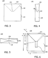
- Fig. 3 shows a side view of a particle trap 120 according to embodiments.
- the trap includes a container 130 having an opening 135.
- Formed into container 130 is a feed hopper 140, typically forming a part of the container.
- the container has the basic shape of a cuboid, wherein one side face of the cuboid is replaced by the larger opening 142 of feed hopper 140, whereas the smaller opening of the feed hopper is typically identical with the opening 135 of the container.
- Fig. 4 shows a cross-sectional side view of particle trap 120 of Fig. 3.
- Fig. 5 shows a top view of the particle trap 120 of Fig. 3 .
- the particle trap 120 includes cardboard or a polymer, for instance, polyethylene, PET, polyester, combinations thereof, or a similar material. Also fibre/resin materials are suitable, like glass fibre or carbon fibre compound. There are no particular restrictions on the material in terms of structural features, as long as the trap may be formed from it to be stable enough to carry its own weight in any direction while being mounted at one face, without being deformed.
- Fig. 6 is a perspective view of the particle trap 120 of Fig. 3 according to embodiments, with an additional tube section 136 connected to the opening 135.
- the tube section may further improve the trapping capabilities.
- typical dimensions of an embodiment of a particle trap are marked as a, b, c, and d. The dimensions are strongly dependent on the size of the wind turbine in which the trap is employed, and more specifically on the dimensions, shape and inner structure of the rotor blades.
- Exemplary ranges for wind turbines with a power output from 1.5 to 3 MW are: Dimensions a and b from 1 m to 3 m, more typically from 1.5 m to 2.5 m; dimension c from 0.15 m to 0.8 m, more typically from 0.2 m to 0.5 m.
- the area of opening 135 of the feed hopper may have a size from 0.005 m 2 up to 0.2 m 2 , more typically from 0.01 m 2 to 0.1 m 2 .
- the opening typically has a rectangular, square or round shape; also other forms of the opening 135 are possible.
- Dimension d is the distance between opening 135 and the larger opening 142 of the feed hopper. Dimension d may be from 0.5 m to 2.8 m, more typically from 1.2 m to 2 m.
- the particle trap is typically located inside a rotor blade 22 of a wind turbine 10, as shown in Fig. 7 .
- three traps 120 are located in a root portion 24 of a rotor blade 22 each.
- the larger openings 142 of the feed hoppers 140 are directed in a direction of the tip portions 160 of the rotor blades 22.
- the rotor blades 22 in Fig. 7 are shown in a position where the pitch angle has a maximum.
- the rotor blades are typically, but not necessarily, positioned differently, typically in a feathered position, which is laid out further below.
- particle traps 120 may be positioned at any position inside the rotor blade 22, and the opening 142 may be directed into a variety of directions, for instance, facing towards the tip region of the blade, towards the root portion, or in an oblique angle with respect to the longitudinal axis of the blade. If the trap is positioned close to a root portion, the accessibility for maintenance is optimal. In case of maintenance, the trap may be cleaned of particles by service personnel, e.g. using a type of vacuum cleaner. For this purpose, an extra opening may be provided in the container section.
- Fig. 8 is a cross sectional view through rotor blade 22.
- Fig. 9 shows another cross-sectional view of the rotor blade 22 and the trap 120.
- the larger opening 142 of the feed hopper 140 is typically replacing one of the side faces of the container 130.
- the feed hopper may be formed as a device separate from the container, and its smaller opening may be connected to an opening in a side face of container 130.
- the particle trap is mounted to one of the inner faces of the rotor blade 22. In the upper part of Fig. 9 , it is mounted to an inner face 137, and in the lower part of Fig. 9 it is mounted to an inner face 138. Both options may be applied, they may even be combined in one rotor blade.
- the container 130 of trap 120 which is basically a cuboid, can be mounted to an inner face 137, 138 of the blade 22 by any suitable method such as gluing, laminating, using screws, or other fixation methods known to the skilled person.
- the container 130 may be produced to have a certain curvature in order to be able to be seamlessly mounted to the inner face of blade 22.
- the trap may also be located at other positions inside the rotor blade, for instance at the inner faces close to or at the trailing edge or the leading edge. In these cases, the form of the container has to be adapted due to the limitations of available space in those regions of the blade.
- the material should provide enough flexibility, so that the particle trap may be slightly deformed during mounting, so that the face of the particle trap 130 contacting the inner face of the blade may be seamlessly connected such as shown in the upper part of Fig. 9 .
- the particle trap is formed from cardboard, for instance, a thickness of the material of 1 to 3 mm may provide for enough flexibility of the trap.
- the properties of the material, the dimensions of the trap and the curvature of the inner face of the blade should be taken into account, which is a standard task for a skilled person.
- the appropriate outer dimensions of the particle traps according to embodiments are strongly dependent on the dimensions of the wind turbine rotor blades in which they are applied. Suitable dimensions will be easily derived by the skilled person from the illustrations provided and this description. Further, depending on the individual use case, the form of the particle trap may have to be modified from the examples described, for instance when taking into account particular geometrical limitations by structural elements inside a rotor blade.
- Fig. 10 shows a wind turbine 10 according to embodiments, having two particle traps 120 located in each rotor blade 22.
- One trap is positioned in the root section 150 and one trap is located in the tip section 160 of each blade 22.
- the two detailed sectional views on the right of Fig. 10 show the trap 120 in the root section 24 (above) and the trap 120 in the tip section 160 (below).
- the larger openings 142 of the feed hoppers 140 are each directed to the respective other end section of the rotor blade 22.
- Figs. 11 to 13 show partial views (only one rotor blade for illustrational purposes) of a wind turbine rotor having a rotatable hub 20 and a rotor blade 22 mounted thereto.
- the rotor blade is shown in different rotational angles about the rotational axis of hub 20, illustrating the different positions of a rotor blade when the rotor of a wind turbine 10 according to embodiments is turned.
- the rotor blade is typically in a feathered position, which complies to the typical pitch angle during idle or standstill of the wind turbine.
- the feathered position of the blades is typically the most appropriate position for the trap to work as described.
- the wind turbine is, in this particular case, in idle mode and typically does not produce electricity.
- the rotor is turned at a slow rate by the wind, for instance at 0.1 to 1.5 rotations per minute, because the rotor blades in a feathered (idle) position do not exert a significant torque.
- the rotor moves significantly slower than during normal operation of the turbine and the blades are in a feathered position.
- other pitch angles of the blades may allow collection of particles with the traps 120 as well. For instance, if a trap is located close to a trailing edge in the rotor blade 22, particles may also be collected during normal operation of the wind turbine, i.e., when the rotor blades have a pitch angle significantly different from the pitch angle according to a feathered position.
- Fig. 11 the rotor blade is moving upwards.
- particles 200 moving around freely inside rotor blade 22 are sliding/moving through gravitational forces in a direction to the larger opening 142 of the feed hopper 140 of particle trap 120.
- two particles are already inside feed hopper 140, where they are guided by the faces of the feed hopper in a direction of the opening 135 of the container 130 of trap 120.
- Fig. 12 the rotor has proceeded further in its rotational movement, and the rotor blade 22 is almost vertical.
- the sectional view on the right shows how particles 200 are falling into container 130 of trap 120. Some particles have already passed opening 135, some have fallen down to the lowest face (with respect to a ground level) of the container 130.
- Fig. 13 shows a further advanced position of rotor blade 22 during the turning of the rotor. All particles 200 shown in previous Figs. 11 and 12 are collected in the container 130 of trap 120. As the rotor has advanced and the larger opening 142 of the feed hopper 140 is now facing left/downwards, the particles 200 have slided along inner faces of the container 130, whereby they did not pass the opening 135. As is obvious, when the rotor proceeds in turning from the position shown in Fig. 13 , the particles 200 will slide along the inner faces of container 130 of trap 120, but will not fall out through opening 135. Thus, they are trapped inside particle trap 120 and are no longer able to move around along the inside of rotor blade 22, where they could cause noise or even damage.
- the particle trap is designed for the trapping of particles during normal operation of the wind turbine, the above described process may be influenced by centripetal forces acting on the particles due to faster movement of the rotor.
- the above-described systems and methods facilitate to collect freely moving particles from the inside of wind turbine rotor blades. More specifically, they prevent freely moving particles from causing noise and/or damage.
Landscapes
- Engineering & Computer Science (AREA)
- Life Sciences & Earth Sciences (AREA)
- Sustainable Development (AREA)
- Sustainable Energy (AREA)
- Chemical & Material Sciences (AREA)
- Combustion & Propulsion (AREA)
- Mechanical Engineering (AREA)
- General Engineering & Computer Science (AREA)
- Wind Motors (AREA)
- Separating Particles In Gases By Inertia (AREA)
Applications Claiming Priority (1)
| Application Number | Priority Date | Filing Date | Title |
|---|---|---|---|
| US13/013,933 US8840367B2 (en) | 2011-01-26 | 2011-01-26 | System and method for collecting particles in a wind turbine rotor blade |
Publications (2)
| Publication Number | Publication Date |
|---|---|
| EP2481925A2 true EP2481925A2 (de) | 2012-08-01 |
| EP2481925A3 EP2481925A3 (de) | 2014-12-31 |
Family
ID=44560165
Family Applications (1)
| Application Number | Title | Priority Date | Filing Date |
|---|---|---|---|
| EP12151439.2A Withdrawn EP2481925A3 (de) | 2011-01-26 | 2012-01-17 | System und Verfahren zum Sammeln von Partikeln eines Windturbinenrotorblatts |
Country Status (4)
| Country | Link |
|---|---|
| US (1) | US8840367B2 (de) |
| EP (1) | EP2481925A3 (de) |
| CN (1) | CN102619701A (de) |
| IN (1) | IN2012DE00160A (de) |
Families Citing this family (2)
| Publication number | Priority date | Publication date | Assignee | Title |
|---|---|---|---|---|
| CN108194288B (zh) * | 2017-12-26 | 2019-12-20 | 北京金风科创风电设备有限公司 | 叶片收胶装置、叶片、风力发电机组及收胶方法 |
| US11298899B2 (en) * | 2019-06-24 | 2022-04-12 | Textron Innovations Inc. | System and method for repairing a composite structure |
Family Cites Families (10)
| Publication number | Priority date | Publication date | Assignee | Title |
|---|---|---|---|---|
| IL134693A0 (en) * | 2000-02-23 | 2001-04-30 | Kulicke & Soffa Investments | Attachment for a dicing saw |
| US6749670B2 (en) * | 2001-03-26 | 2004-06-15 | Shell Oil Company | Process for trapping particulate matter in hot gas and trap therefor |
| JP4298452B2 (ja) * | 2003-09-30 | 2009-07-22 | 大和ハウス工業株式会社 | 風車翼内の排水機構 |
| DK176019B1 (da) * | 2004-12-29 | 2005-12-12 | Lm Glasfiber As | Vinge til vindenergianlæg udstyret med opsamlingsmidler |
| EP1775463A1 (de) * | 2005-10-13 | 2007-04-18 | ECOTECNIA, s.coop. c.l. | Windturbinenblatt |
| US20090035148A1 (en) * | 2007-08-02 | 2009-02-05 | General Electric Company | Wind Turbine Blade Drainage |
| US8262363B2 (en) * | 2008-03-17 | 2012-09-11 | General Electric Company | Blade having a damping element and method of fabricating same |
| DE102009019453B3 (de) * | 2008-05-13 | 2010-09-30 | Suzlon Energy Gmbh | Schaltschrank für eine Windturbine |
| US20090297352A1 (en) * | 2008-05-30 | 2009-12-03 | Zulu-Revolutions, Inc. | Debris removal system and method for wind turbine blades |
| US8206107B2 (en) * | 2009-04-13 | 2012-06-26 | Frontier Wind, Llc | Variable length wind turbine blade having transition area elements |
-
2011
- 2011-01-26 US US13/013,933 patent/US8840367B2/en not_active Expired - Fee Related
-
2012
- 2012-01-17 EP EP12151439.2A patent/EP2481925A3/de not_active Withdrawn
- 2012-01-19 IN IN160DE2012 patent/IN2012DE00160A/en unknown
- 2012-01-20 CN CN2012100310992A patent/CN102619701A/zh active Pending
Non-Patent Citations (1)
| Title |
|---|
| None |
Also Published As
| Publication number | Publication date |
|---|---|
| IN2012DE00160A (de) | 2015-06-12 |
| US20110223019A1 (en) | 2011-09-15 |
| EP2481925A3 (de) | 2014-12-31 |
| CN102619701A (zh) | 2012-08-01 |
| US8840367B2 (en) | 2014-09-23 |
Similar Documents
| Publication | Publication Date | Title |
|---|---|---|
| DK2679805T3 (en) | Cone angle insert for wind turbine rotor | |
| DK2306002T3 (en) | Systems and methods for assembling a pitch control device for use in a wind turbine | |
| US8303250B2 (en) | Method and apparatus for increasing lift on wind turbine blade | |
| EP2559891A2 (de) | Windturbinenblatt und Schutzverfahren dafür | |
| EP2267298A2 (de) | Windturbineblatt mit drehbaren Finnen an der Spitze | |
| EP2466121A2 (de) | Windturbine, aerodynamische Anordnung für die Verwendung in einer Windturbine und Verfahren zur Anordnung davon | |
| EP2674614A2 (de) | Kegelwinkeleinsatz für einen Windturbinenrotor | |
| US20100329879A1 (en) | Wind turbine blades with mixer lobes | |
| US9109578B2 (en) | Root extender for a wind turbine rotor blade | |
| EP2108822A2 (de) | Winddeflektor für Windrad und Windrad, das diesen Deflektor integriert hat | |
| CN108678908B (zh) | 偏航塔筒段、塔筒及风力发电机组 | |
| EP2416006A2 (de) | Gieranordnung für eine Windturbine | |
| EP2497878A2 (de) | Flansch und Windenergiesystem | |
| KR101387669B1 (ko) | 풍력 에너지로부터 전력을 발생시키기 위한 풍력 발전 장치 | |
| US20110206510A1 (en) | Modular rotor blade and method for mounting a wind turbine | |
| CN101451491A (zh) | 多段式风力涡轮机转子叶片及结合该叶片的风力涡轮机 | |
| CN102555116A (zh) | 用于生产转子叶片的方法和装置 | |
| WO2016154757A1 (en) | Closed loop multiple airfoil wind turbine | |
| US20200095975A1 (en) | Cascaded wind turbine | |
| CA2892050C (en) | Wind turbine rotor and methods of assembling the same | |
| US8840367B2 (en) | System and method for collecting particles in a wind turbine rotor blade | |
| US20250179989A1 (en) | Wind turbine including pivotable blades and annular shroud | |
| WO2012069905A2 (en) | A wind turbine | |
| KR100906811B1 (ko) | 수직축형 풍력 발전 장치 | |
| KR200444966Y1 (ko) | 풍력 발전기 |
Legal Events
| Date | Code | Title | Description |
|---|---|---|---|
| PUAI | Public reference made under article 153(3) epc to a published international application that has entered the european phase |
Free format text: ORIGINAL CODE: 0009012 |
|
| AK | Designated contracting states |
Kind code of ref document: A2 Designated state(s): AL AT BE BG CH CY CZ DE DK EE ES FI FR GB GR HR HU IE IS IT LI LT LU LV MC MK MT NL NO PL PT RO RS SE SI SK SM TR |
|
| AX | Request for extension of the european patent |
Extension state: BA ME |
|
| PUAL | Search report despatched |
Free format text: ORIGINAL CODE: 0009013 |
|
| AK | Designated contracting states |
Kind code of ref document: A3 Designated state(s): AL AT BE BG CH CY CZ DE DK EE ES FI FR GB GR HR HU IE IS IT LI LT LU LV MC MK MT NL NO PL PT RO RS SE SI SK SM TR |
|
| AX | Request for extension of the european patent |
Extension state: BA ME |
|
| RIC1 | Information provided on ipc code assigned before grant |
Ipc: F03D 11/00 20060101AFI20141126BHEP |
|
| 17P | Request for examination filed |
Effective date: 20150630 |
|
| RBV | Designated contracting states (corrected) |
Designated state(s): AL AT BE BG CH CY CZ DE DK EE ES FI FR GB GR HR HU IE IS IT LI LT LU LV MC MK MT NL NO PL PT RO RS SE SI SK SM TR |
|
| STAA | Information on the status of an ep patent application or granted ep patent |
Free format text: STATUS: THE APPLICATION IS DEEMED TO BE WITHDRAWN |
|
| 18D | Application deemed to be withdrawn |
Effective date: 20170801 |
|
| P01 | Opt-out of the competence of the unified patent court (upc) registered |
Effective date: 20230522 |