EP2481663A2 - Mécanisme pliable de guidon pour véhicule motorisé pliable - Google Patents
Mécanisme pliable de guidon pour véhicule motorisé pliable Download PDFInfo
- Publication number
- EP2481663A2 EP2481663A2 EP12152685A EP12152685A EP2481663A2 EP 2481663 A2 EP2481663 A2 EP 2481663A2 EP 12152685 A EP12152685 A EP 12152685A EP 12152685 A EP12152685 A EP 12152685A EP 2481663 A2 EP2481663 A2 EP 2481663A2
- Authority
- EP
- European Patent Office
- Prior art keywords
- locking
- handlebar
- locking lever
- connecting member
- mounting base
- Prior art date
- Legal status (The legal status is an assumption and is not a legal conclusion. Google has not performed a legal analysis and makes no representation as to the accuracy of the status listed.)
- Withdrawn
Links
Images


Classifications
-
- B—PERFORMING OPERATIONS; TRANSPORTING
- B62—LAND VEHICLES FOR TRAVELLING OTHERWISE THAN ON RAILS
- B62K—CYCLES; CYCLE FRAMES; CYCLE STEERING DEVICES; RIDER-OPERATED TERMINAL CONTROLS SPECIALLY ADAPTED FOR CYCLES; CYCLE AXLE SUSPENSIONS; CYCLE SIDECARS, FORECARS, OR THE LIKE
- B62K15/00—Collapsible or foldable cycles
- B62K15/006—Collapsible or foldable cycles the frame being foldable
-
- B—PERFORMING OPERATIONS; TRANSPORTING
- B62—LAND VEHICLES FOR TRAVELLING OTHERWISE THAN ON RAILS
- B62K—CYCLES; CYCLE FRAMES; CYCLE STEERING DEVICES; RIDER-OPERATED TERMINAL CONTROLS SPECIALLY ADAPTED FOR CYCLES; CYCLE AXLE SUSPENSIONS; CYCLE SIDECARS, FORECARS, OR THE LIKE
- B62K19/00—Cycle frames
- B62K19/30—Frame parts shaped to receive other cycle parts or accessories
- B62K19/36—Frame parts shaped to receive other cycle parts or accessories for attaching saddle pillars, e.g. adjustable during ride
-
- B—PERFORMING OPERATIONS; TRANSPORTING
- B62—LAND VEHICLES FOR TRAVELLING OTHERWISE THAN ON RAILS
- B62K—CYCLES; CYCLE FRAMES; CYCLE STEERING DEVICES; RIDER-OPERATED TERMINAL CONTROLS SPECIALLY ADAPTED FOR CYCLES; CYCLE AXLE SUSPENSIONS; CYCLE SIDECARS, FORECARS, OR THE LIKE
- B62K21/00—Steering devices
- B62K21/12—Handlebars; Handlebar stems
-
- B—PERFORMING OPERATIONS; TRANSPORTING
- B62—LAND VEHICLES FOR TRAVELLING OTHERWISE THAN ON RAILS
- B62K—CYCLES; CYCLE FRAMES; CYCLE STEERING DEVICES; RIDER-OPERATED TERMINAL CONTROLS SPECIALLY ADAPTED FOR CYCLES; CYCLE AXLE SUSPENSIONS; CYCLE SIDECARS, FORECARS, OR THE LIKE
- B62K5/00—Cycles with handlebars, equipped with three or more main road wheels
- B62K5/003—Cycles with four or more wheels, specially adapted for disabled riders, e.g. personal mobility type vehicles with four wheels
- B62K5/007—Cycles with four or more wheels, specially adapted for disabled riders, e.g. personal mobility type vehicles with four wheels power-driven
-
- B—PERFORMING OPERATIONS; TRANSPORTING
- B62—LAND VEHICLES FOR TRAVELLING OTHERWISE THAN ON RAILS
- B62K—CYCLES; CYCLE FRAMES; CYCLE STEERING DEVICES; RIDER-OPERATED TERMINAL CONTROLS SPECIALLY ADAPTED FOR CYCLES; CYCLE AXLE SUSPENSIONS; CYCLE SIDECARS, FORECARS, OR THE LIKE
- B62K2204/00—Adaptations for driving cycles by electric motor
Definitions
- the present invention relates to a foldable motorized vehicle, and more particularly to a handlebar folding mechanism mounted on a foldable motorized vehicle for folding and locking of handlebar.
- a steering handle In a conventional handlebar of foldable motorized vehicle, multiple locking holes are needed in a steering handle, the steering handle is pivoted on a bicycle handle main body, the steering handle is positioned by passing a locking shaft pin through one of the locking holes, and during folding, the steering handle is rotated so that the locking shaft pin passes through different locking holes, thereby achieving an objective of folding and locking. During locking and unlocking, the locking shaft pin is required to enter into or withdraw from the locking holes repeatedly.
- the present invention is related to a handlebar folding mechanism for a foldable motorized vehicle.
- the handlebar folding mechanism includes: (a) a mounting base, (b) a first connecting member and a second connecting member, (c) a first locking lever and a second locking lever, (d) a steering axial rod, and (e) a first steering handlebar and a second steering handlebar.
- the mounting base has a first end, a second end, a front sidewall, a rear sidewall, a first pivoting hole, a second pivoting hole, a first locking hole, and a second locking hole.
- Each of the first connecting member and the second connecting member has a connection portion and a locking portion.
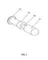
- the steering axial rod has a top end and bottom end.
- the bottom end of the steering axial rod is connected to a front wheel stem of the foldable motorized vehicle, and the top end of the steering axial rod is connected to the center of the mounting base.
- Each of the first steering handlebar and the second steering handlebar has an inside end and outside end.
- connection portion of the first connecting member is connected to the inside end of the first steering handlebar
- connection portion of the second connecting member is connected to the inside end of the second steering handlebar, respectively.
- the locking portion of the first connecting member is pivoted on the first pivoting hole of the mounting base
- the locking portion of the second connecting member is pivoted on the second pivoting hole of the mounting base, respectively.
- the first locking lever is retractably mounted in the first locking hole of the mounting base to control the rotation of the first connecting member
- the second locking lever is retractably mounted in the second locking hole of the mounting base to control the rotation of the second connecting member.
- a side surface of the locking portion of the first connecting member is recessed along a folding direction of the first steering handlebar to form an arc-shaped sliding portion with each of the sliding portion forming a side edge
- a side surface of the locking portion of the second connecting member is recessed along a folding direction of the second steering handlebar to form an arc-shaped sliding portion with each of the sliding portion forming a side edge.
- the sliding portion of the first connecting member protrudes along the folding direction of the first steering handlebar to form a protruding edge
- the sliding portion of the second connecting member protrudes along the folding direction of the second steering handlebar to form a protruding edge.
- the protruding edge of the first connecting member divides its sliding portion into two parts, both ends of the protruding edge form a locking slot with a side edge of a recessed part of the sliding portion, and the protruding edge of the second connecting member divides its sliding portion into two parts, both ends of the protruding edge form a locking slot with a side edge of a recessed part of the sliding portion.
- the each of the first locking lever and the second locking lever has (a) a front pressing portion, (b) a rear pressing portion, (c) a flange, and (d) a release slot.
- the first locking lever protrudes radially to form a front pressing portion at a front end of the first locking lever, wherein the front pressing portion pass through the first locking hole of the front sidewall of the mounting base in an elastically retractable manner
- the second locking lever protrudes radially to form a front pressing portion formed at a front end of the second locking lever, wherein the front pressing portion pass through the second locking hole of the front sidewall of the mounting base in an elastically retractable manner.
- the rear pressing portion of the first locking lever and the second locking lever are formed at a rear end of the locking levers, and the rear pressing portions presses against the rear sidewall of the mounting base.
- the flange corresponds to the locking slots of the first connection member and the second connection member.
- the release slot for the protruding edge to pass through is formed between the front pressing portion and the flange.
- the locking slot extends and runs through the side edge of the recessed part of the sliding portion.
- the angle between the two locking slots formed by the two ends of the protruding edge and the side edges of the recessed part of the sliding portion is about 90°.
- the protruding edge is arc-shaped.
- the handlebar folding mechanism further comprises a first spring, and a second spring.
- the first spring is sleeved on the first locking lever and presses between the flange of the first locking lever and the rear sidewall of the mounting base.
- the second spring is sleeved on the second locking lever and presses between the flange of the second locking lever and the rear sidewall of the mounting base.
- the release slot of the first locking lever moves backward towards the rear sidewall of the mounting base along one of the locking slots such that the protruding edge pass through the release slot of the first locking lever and the first handlebar can be rotated.
- the release slot of the second locking lever moves backward towards the rear sidewall of the mounting base along one of the locking slots such that the protruding edge pass through the release slot of the second locking lever and the second handlebar can be rotated.
- the present invention relates to a foldable motorized vehicle comprising the handlebar folding mechanism as disclosed above.
- FIG. 1 a perspective view of a foldable motorized vehicle is shown according one embodiment of the present invention.
- the foldable motorized vehicle has: (a) a foldable frame body 20, (b) a foldable seat mounting rack 10, (c) a seat 30, (d) a front wheel steering mechanism 40, and (e) handlebar folding mechanism 100 with two foldable handlebars 300A and 300B, and a steering axial rod 200.
- the seat, the frame body, and steering are all foldable so that the entire vehicle is foldable to save storage space.
- the handlebar folding mechanism 100 for a foldable motorized vehicle has: (a) a mounting base 1, (b) a first connecting member 2A and a second connecting member 2A, (c) a first locking lever 3A and a second locking lever 3B, (d) a steering axial rod 200, and (e) a first steering handlebar 300A and a second steering handlebar 300B.
- the mounting base 1 has a first end 1A, a second end 1B, a front sidewall 11, a rear sidewall 12, a first pivoting hole 13A, a second pivoting hole 13B, a first locking hole 14A, and a second locking hole of 14B.
- Each of the first connecting member 2A and the second connecting member 2B has a connection portion 21 and a locking portion 22.
- the steering axial rod 200 has a top end 200C and bottom end 200D. The bottom end 200D of the steering axial rod 200 is connected to a front wheel stem of the foldable motorized vehicle, and the top end 200C of the steering axial rod 200 is connected to the center of the mounting base 1.
- Each of the first steering handlebar 300A and the second steering handlebar 300B has an inside end 300C and outside end 300D.
- the connection portion 21 of the first connecting member 2A is connected to the inside end 300C of the first steering handlebar 300A and the connection portion 21 of the second connecting member 2A is connected to the inside end 300C of the second steering handlebar 300B, respectively.
- the locking portion 22 of the first connecting member 2A is pivoted on the first pivoting hole 13A of the mounting base 1, and the locking portion 22 of the second connecting member 2B is pivoted on the second pivoting hole 13B of the mounting base 1, respectively.
- the first locking lever 3A is retractably mounted in the first locking hole 14A of the mounting base 1 to control the rotation of the first connecting member 2A
- the second locking lever 3B is retractably mounted in the second locking hole 14B of the mounting base 1 to control the rotation of the second connecting member 2B.
- a side surface of the locking portion 22 of the first connecting member 2A is recessed along a folding direction of the first steering handlebar 300A to form an arc-shaped sliding portion 222 with each of the sliding portion forming a side edge 222a
- a side surface of the locking portion 22 of the second connecting member 2B is recessed along a folding direction of the second steering handlebar 300B to form an arc-shaped sliding portion 222 with each of the sliding portion forming a side edge 222a.
- the sliding portion 222 of the first connecting member 2A protrudes along the folding direction of the first steering handlebar 300A to form a protruding edge 221
- the sliding portion 222 of the second connecting member 2B protrudes along the folding direction of the second steering handlebar 300B to form a protruding edge 221.
- the protruding edge 221 of the first connecting member 2A divides its sliding portion 222 into two parts, both ends of the protruding edge 221 form a locking slot 221a with a side edge of a recessed part of the sliding portion 222, and the protruding edge 221 of the second connecting member 2B divides its sliding portion 222 into two parts, both ends of the protruding edge 221 form a locking slot 221a with a side edge of a recessed part of the sliding portion 222.
- the first locking lever 3A and the second locking lever 3B protrudes radially to form (a) a front pressing portion 31, (b) a rear pressing portion 32, (c) a flange 33, and (d) a release slot 34.
- the front pressing portion 31 is formed at the front end of the first locking lever 3A and the front end of the second locking lever 3B.
- the front pressing portion 31 pass through the first locking hole 14A and the second locking hole 14B of the front sidewall 11 I of the mounting base 1 in an elastically retractable manner.
- the rear pressing portion 32 is formed at the rear end of the first locking lever 3A and the second locking lever 3B.
- the rear pressing portion 32 presses against the rear sidewall 12 of the mounting base 1.
- the flange 33 corresponds to the locking slot 221a of the first connection member 2A and the locking slot 221a of the second connection member 2B.
- the release slot 34 for the protruding edge 221 to pass through is formed between the front pressing portion 31 and the flange 33.
- the handlebar folding mechanism 100 further includes a first spring 4A, and a second spring 4B.
- the first spring 4A is sleeved on the first locking lever 3A and presses between the flange 33 of the first locking lever 3A and the rear sidewall 12 of the mounting base 1
- the second spring 4B is sleeved on the second locking lever 3B and presses between the flange 33 of the second locking lever 3B and the rear sidewall 12 of the mounting base 1.
- the locking slot 221a extends and runs through the side edge 222a of the recessed part of the sliding portion 222.
- the angle between the two locking slots 221a formed by the two ends of the protruding edge 221 and the side edges 222a of the recessed part of the sliding portion 222 is about 90°.
- the protruding edge 221 is arc-shaped.
- the release slot 34 of the first locking lever 3A moves backward towards the rear sidewall 12 of the mounting base 1 along one of the locking slots 221a such that the protruding edge 221 pass through the release slot 34 of the first locking lever 3A and the first handlebar 300A can be rotated, thus the first handlebar 300A and the first connecting member 2A can be folded or unfolded.
- the release slot 34 of the second locking lever 3B moves backward towards the rear sidewall 12 of the mounting base 1 along one of the locking slots 221 a such that the protruding edge 221 pass through the release slot 34 of the second locking lever 3B and the second handlebar 300B can be rotated, thus the second handlebar 300B and the second connecting member 2B can be folded or unfolded.
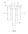
- FIG. 4 shows a side view of a handlebar folding mechanism when both handlebars are folded and locked.
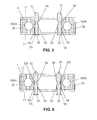
- FIG. 5 shows a sectional view of a handlebar folding mechanism when both handlebars are locked along an A-A direction in FIG. 4 .
- FIG. 6 shows a sectional view of a handlebar folding mechanism when both handlebars are unlocked along an A-A direction in FIG. 4 .
- FIG. 7 shows a perspective view of a handlebar folding mechanism when both handlebars are unfolded and locked according to one embodiment of the present invention.
- FIG. 8 shows a perspective view of a handlebar folding mechanism when both handlebars are folded and locked according to one embodiment of the present invention.
- a handlebar folding mechanism for a foldable motorized vehicle comprising: (a) a mounting base, (b) a first connecting member and a second connecting member, each having a connection portion and a locking portion, (c) a first locking lever and a second locking lever, (d) a steering axial rod and (e) a first steering handlebar and a second steering handlebar, each of the steering handlebar having an inside end and outside end, wherein the connection portions of the connecting members are connected to the inside end of the first steering handlebar, the locking portions of the connecting members are pivoted on the mounting base, the locking levers are retractably mounted in the mounting base to control the rotation of the connecting members.
Landscapes
- Engineering & Computer Science (AREA)
- Mechanical Engineering (AREA)
- Steering Devices For Bicycles And Motorcycles (AREA)
- Motorcycle And Bicycle Frame (AREA)
Applications Claiming Priority (3)
| Application Number | Priority Date | Filing Date | Title |
|---|---|---|---|
| CN2011200298578U CN202029936U (zh) | 2011-01-28 | 2011-01-28 | 安装支架 |
| CN201120029840 | 2011-01-28 | ||
| US13/357,310 US8381858B2 (en) | 2011-01-28 | 2012-01-24 | Handlebar folding mechanism and foldable motorized vehicle having same |
Publications (2)
| Publication Number | Publication Date |
|---|---|
| EP2481663A2 true EP2481663A2 (fr) | 2012-08-01 |
| EP2481663A3 EP2481663A3 (fr) | 2013-05-29 |
Family
ID=45497910
Family Applications (1)
| Application Number | Title | Priority Date | Filing Date |
|---|---|---|---|
| EP12152685.9A Withdrawn EP2481663A3 (fr) | 2011-01-28 | 2012-01-26 | Mécanisme pliable de guidon pour véhicule motorisé pliable |
Country Status (1)
| Country | Link |
|---|---|
| EP (1) | EP2481663A3 (fr) |
Cited By (2)
| Publication number | Priority date | Publication date | Assignee | Title |
|---|---|---|---|---|
| FR3013026A1 (fr) * | 2013-11-08 | 2015-05-15 | Antoine Cirier | Dispositif de transport urbain du type trottinette |
| IT202300007734A1 (it) | 2023-04-20 | 2024-10-20 | Unik Innovation Srl | Manubrio pieghevole per bicicli, monopattini e simili |
Families Citing this family (2)
| Publication number | Priority date | Publication date | Assignee | Title |
|---|---|---|---|---|
| CN106553730B (zh) * | 2015-09-28 | 2019-09-13 | 张芹 | 一种滑板车的折叠机构及包含该折叠机构的滑板车 |
| CN105752241A (zh) * | 2016-02-22 | 2016-07-13 | 王昆隆 | 变形传动代步车 |
Family Cites Families (9)
| Publication number | Priority date | Publication date | Assignee | Title |
|---|---|---|---|---|
| DE885964C (de) * | 1951-07-07 | 1953-08-10 | Ernst-Heinz Quidde | Lenker fuer Fahrraeder, Motorraeder u. dgl. |
| US4417745A (en) * | 1981-03-16 | 1983-11-29 | Shomo Robert D | Folding bicycle |
| US6301749B1 (en) * | 2000-04-11 | 2001-10-16 | Ching Chiuan Chen | Scooter having foldable hand grips |
| CN2419158Y (zh) * | 2000-05-01 | 2001-02-14 | 钲尚机械(深圳)有限公司 | 折叠车把 |
| BR8100960Y1 (pt) * | 2001-03-27 | 2010-08-10 | conjunto de otimização de espaço para guarda ou armazenamento de bicicletas. | |
| TWM270112U (en) * | 2005-01-03 | 2005-07-11 | J D Components Co Ltd | Foldable handlebar for vehicle |
| CN101293552B (zh) * | 2007-04-26 | 2011-05-11 | 梁德 | 折叠车把 |
| CN201099342Y (zh) * | 2007-09-14 | 2008-08-13 | 武济群 | 电动滑板车的驱动装置 |
| CN201099328Y (zh) * | 2007-09-14 | 2008-08-13 | 武济群 | 折叠车把 |
-
2012
- 2012-01-26 EP EP12152685.9A patent/EP2481663A3/fr not_active Withdrawn
Non-Patent Citations (1)
| Title |
|---|
| None |
Cited By (2)
| Publication number | Priority date | Publication date | Assignee | Title |
|---|---|---|---|---|
| FR3013026A1 (fr) * | 2013-11-08 | 2015-05-15 | Antoine Cirier | Dispositif de transport urbain du type trottinette |
| IT202300007734A1 (it) | 2023-04-20 | 2024-10-20 | Unik Innovation Srl | Manubrio pieghevole per bicicli, monopattini e simili |
Also Published As
| Publication number | Publication date |
|---|---|
| EP2481663A3 (fr) | 2013-05-29 |
Similar Documents
| Publication | Publication Date | Title |
|---|---|---|
| US8381858B2 (en) | Handlebar folding mechanism and foldable motorized vehicle having same | |
| EP3335970B1 (fr) | Véhicule de mobilité personnelle pliant | |
| CN107010149B (zh) | 带轮子的车辆 | |
| US8459679B2 (en) | Pivot mechanism for scooters, tricycles and the like | |
| US9580131B1 (en) | Foldable child's tricycle and folding method thereof | |
| US9227465B2 (en) | Bicycle wheel securing structure | |
| EP2612808B1 (fr) | Mécanisme de guidon pliable et véhicule pliable muni de celui-ci | |
| US9174661B2 (en) | Armrest folding device for a foldable stroller | |
| US9932082B2 (en) | Bicycle handlebar | |
| EP3507177B1 (fr) | Trottinette pliante anti-cliquetis | |
| JP2015224023A (ja) | 折り畳み式ベビーカー用のヒンジ組立体 | |
| EP2481663A2 (fr) | Mécanisme pliable de guidon pour véhicule motorisé pliable | |
| EP2524853B1 (fr) | Landau pour bébé | |
| EP3623272B1 (fr) | Mécanisme de pliage et trottinette | |
| JP6300745B2 (ja) | 折り畳み式車両 | |
| JP2009526679A (ja) | 子供用手押し車 | |
| CN102616326A (zh) | 手柄折叠机构 | |
| KR101537923B1 (ko) | 접이식 자전거 | |
| JP6001000B2 (ja) | 鞍乗型車両のステップ構造 | |
| JP5548747B2 (ja) | スライド部材のロック装置およびこのロック装置を備えた手押し車 | |
| CN106741449B (zh) | 一种旋转组件及折叠车 | |
| JP5613492B2 (ja) | ベビーカー用スタンド装置 | |
| CN204161420U (zh) | 折叠式推车 | |
| CN112776932B (zh) | 龙头组件及骑行车 | |
| CN211844750U (zh) | 折叠机构及可折叠车辆 |
Legal Events
| Date | Code | Title | Description |
|---|---|---|---|
| PUAI | Public reference made under article 153(3) epc to a published international application that has entered the european phase |
Free format text: ORIGINAL CODE: 0009012 |
|
| AK | Designated contracting states |
Kind code of ref document: A2 Designated state(s): AL AT BE BG CH CY CZ DE DK EE ES FI FR GB GR HR HU IE IS IT LI LT LU LV MC MK MT NL NO PL PT RO RS SE SI SK SM TR |
|
| AX | Request for extension of the european patent |
Extension state: BA ME |
|
| PUAL | Search report despatched |
Free format text: ORIGINAL CODE: 0009013 |
|
| AK | Designated contracting states |
Kind code of ref document: A3 Designated state(s): AL AT BE BG CH CY CZ DE DK EE ES FI FR GB GR HR HU IE IS IT LI LT LU LV MC MK MT NL NO PL PT RO RS SE SI SK SM TR |
|
| AX | Request for extension of the european patent |
Extension state: BA ME |
|
| RIC1 | Information provided on ipc code assigned before grant |
Ipc: B62K 21/12 20060101ALI20130425BHEP Ipc: B62K 15/00 20060101AFI20130425BHEP |
|
| 17P | Request for examination filed |
Effective date: 20131128 |
|
| RBV | Designated contracting states (corrected) |
Designated state(s): AL AT BE BG CH CY CZ DE DK EE ES FI FR GB GR HR HU IE IS IT LI LT LU LV MC MK MT NL NO PL PT RO RS SE SI SK SM TR |
|
| STAA | Information on the status of an ep patent application or granted ep patent |
Free format text: STATUS: THE APPLICATION HAS BEEN WITHDRAWN |
|
| 18W | Application withdrawn |
Effective date: 20140102 |