EP2481659B1 - Wheel automatic adjustment mechanism and foldable motorized vehicle having same - Google Patents
Wheel automatic adjustment mechanism and foldable motorized vehicle having same Download PDFInfo
- Publication number
- EP2481659B1 EP2481659B1 EP20120152670 EP12152670A EP2481659B1 EP 2481659 B1 EP2481659 B1 EP 2481659B1 EP 20120152670 EP20120152670 EP 20120152670 EP 12152670 A EP12152670 A EP 12152670A EP 2481659 B1 EP2481659 B1 EP 2481659B1
- Authority
- EP
- European Patent Office
- Prior art keywords
- front wheel
- adjustment mechanism
- supporting shaft
- connecting member
- shock absorber
- Prior art date
- Legal status (The legal status is an assumption and is not a legal conclusion. Google has not performed a legal analysis and makes no representation as to the accuracy of the status listed.)
- Active
Links
- 230000035939 shock Effects 0.000 claims description 26
- 239000006096 absorbing agent Substances 0.000 claims description 25
- 238000012986 modification Methods 0.000 description 4
- 230000004048 modification Effects 0.000 description 4
- 230000005484 gravity Effects 0.000 description 2
- 230000007812 deficiency Effects 0.000 description 1
- 230000001419 dependent effect Effects 0.000 description 1
- 238000005516 engineering process Methods 0.000 description 1
- 238000000034 method Methods 0.000 description 1
Images


Classifications
-
- B—PERFORMING OPERATIONS; TRANSPORTING
- B62—LAND VEHICLES FOR TRAVELLING OTHERWISE THAN ON RAILS
- B62K—CYCLES; CYCLE FRAMES; CYCLE STEERING DEVICES; RIDER-OPERATED TERMINAL CONTROLS SPECIALLY ADAPTED FOR CYCLES; CYCLE AXLE SUSPENSIONS; CYCLE SIDE-CARS, FORECARS, OR THE LIKE
- B62K5/00—Cycles with handlebars, equipped with three or more main road wheels
- B62K5/003—Cycles with four or more wheels, specially adapted for disabled riders, e.g. personal mobility type vehicles with four wheels
- B62K5/007—Cycles with four or more wheels, specially adapted for disabled riders, e.g. personal mobility type vehicles with four wheels power-driven
-
- B—PERFORMING OPERATIONS; TRANSPORTING
- B60—VEHICLES IN GENERAL
- B60G—VEHICLE SUSPENSION ARRANGEMENTS
- B60G11/00—Resilient suspensions characterised by arrangement, location or kind of springs
- B60G11/14—Resilient suspensions characterised by arrangement, location or kind of springs having helical, spiral or coil springs only
-
- B—PERFORMING OPERATIONS; TRANSPORTING
- B60—VEHICLES IN GENERAL
- B60G—VEHICLE SUSPENSION ARRANGEMENTS
- B60G9/00—Resilient suspensions of a rigid axle or axle housing for two or more wheels
- B60G9/02—Resilient suspensions of a rigid axle or axle housing for two or more wheels the axle or housing being pivotally mounted on the vehicle, e.g. the pivotal axis being parallel to the longitudinal axis of the vehicle
-
- B—PERFORMING OPERATIONS; TRANSPORTING
- B60—VEHICLES IN GENERAL
- B60G—VEHICLE SUSPENSION ARRANGEMENTS
- B60G2200/00—Indexing codes relating to suspension types
- B60G2200/30—Rigid axle suspensions
- B60G2200/32—Rigid axle suspensions pivoted
- B60G2200/322—Rigid axle suspensions pivoted with a single pivot point and a straight axle
-
- B—PERFORMING OPERATIONS; TRANSPORTING
- B60—VEHICLES IN GENERAL
- B60G—VEHICLE SUSPENSION ARRANGEMENTS
- B60G2204/00—Indexing codes related to suspensions per se or to auxiliary parts
- B60G2204/10—Mounting of suspension elements
- B60G2204/12—Mounting of springs or dampers
- B60G2204/124—Mounting of coil springs
-
- B—PERFORMING OPERATIONS; TRANSPORTING
- B60—VEHICLES IN GENERAL
- B60G—VEHICLE SUSPENSION ARRANGEMENTS
- B60G2300/00—Indexing codes relating to the type of vehicle
- B60G2300/22—Perambulators
-
- B—PERFORMING OPERATIONS; TRANSPORTING
- B62—LAND VEHICLES FOR TRAVELLING OTHERWISE THAN ON RAILS
- B62K—CYCLES; CYCLE FRAMES; CYCLE STEERING DEVICES; RIDER-OPERATED TERMINAL CONTROLS SPECIALLY ADAPTED FOR CYCLES; CYCLE AXLE SUSPENSIONS; CYCLE SIDE-CARS, FORECARS, OR THE LIKE
- B62K5/00—Cycles with handlebars, equipped with three or more main road wheels
- B62K2005/001—Suspension details for cycles with three or more main road wheels
Definitions
- the present invention relates to an adjustment mechanism, in particular, to an automatic wheel adjustment mechanism mounted between front wheels and a front wheel stem of an foldable motorized vehicle, for ensuring that both front wheels contact the ground while turning.
- four-wheel motorized vehicle are mostly disposed with an angle adjustment mechanism between a front wheel stem and a body rack.
- the angle adjustment mechanism can be used by a driver to adjust the angle freely, so that every driver can hold the handle mounted on the front wheel stem when sitting on a seat to control the handle, meeting requirements of different users, and being convenient in use.
- the two front wheels are generally fixedly connected to the front wheel stem directly, and when the front wheel stem is in a vertical state, the driver can normally control the driving direction of the two front wheels when rotating the front wheel stem to the left or the right.
- the front wheel stem assumes an inclined state with respect to that before the adjustment, so when the electric vehicle turns and the front wheel stem is rotated through the handle, the front wheel stem drives an axle of the two front wheels to swing, thus causing one of the two front wheels tilts with respect to the other one.
- the tilted front wheel cannot travel without leaving the ground, which has a great impact on the driving safety during turning, and the technology used in the current motorized vehicle is unable to solve the above problem.
- a scooter with two steerable front wheels and an automatic wheel adjustment mechanism according to the preamble of claim 1 is known from GB 2 367 541 A .
- the present invention provides an automatic wheel adjustment mechanism having a simple structure and capable of preventing the front wheels of a motorized vehicle from tilting to affect driving safety, as is defined in claim 1.
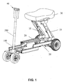
- FIG. 1 a perspective view of a foldable motorized vehicle is shown according one embodiment of the present invention.
- the foldable motorized vehicle has: (a) a foldable frame body 20, (b) a foldable seat mounting rack 10, (c) a seat 30, (d) a front wheel steering mechanism 100, and (e) handlebar folding mechanism 40 with two foldable handlebars, and a steering axial rod 200.
- the seat, the frame body, and steering are all foldable so that the entire vehicle is foldable to save storage space.
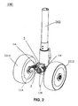
- FIG. 2 offers a closer and detailed view of the automatic wheel adjustment mechanism 100 of the foldable motorized vehicle according to one embodiment of the present invention.
- FIG. 3 an exploded perspective view of the automatic wheel adjustment mechanism is shown according to one embodiment of the present invention.
- the automatic wheel adjustment mechanism includes: (a) a front wheel supporting shaft 1, (b) a connecting member 2, and (c) a plurality of bearings 3.
- the front wheel supporting shaft 1 has a first end 1A , a second end 1 B, a bearing housing 11 positioned on the top center portion of the front wheel supporting shaft 1, a first connecting portion 12A positioned on a first end 1A of the front wheel supporting shaft 1, and a second connecting portion 12B positioned on a second end 1 B of the front wheel supporting shaft 1.
- the connecting member 2 has a ring shaped body 22 on a first end and a connecting shaft 21 on a second end.
- the connecting shaft 21 extends upwards to form a connecting portion 21 a.
- the plurality of the bearings 3 are mounted inside of the bearing housing 11 of the front wheel supporting shaft 1.
- the first front wheel 201A is mounted on the first end 1A of the front wheel supporting shaft 1
- the second front wheel 201 B is mounted on the second end 1 B of the front wheel supporting shaft 1.
- the lower end of the front wheel stem 202 is inserted into the ring shaped body 22 of the connecting member 2 and is fixed onto the ring shaped body 22 of the connecting member 2.
- the connecting shaft 21 of the connecting member 2 is perpendicular to the ring shaped body 22 of the connecting member 2 and protrudes forward from the connecting member 2, and mounted inside of the inner races of the plurality of the bearings 3.
- the automatic wheel adjustment mechanism 100 further includes a first shock absorber 4A and a second shock absorber 4B.
- Each of the first and second shock absorbers comprises a first end portion 41, a second end portion 42, and an elastic element 43.
- the elastic element 43 is disposed obliquely between the first end portion 41, and the second end portion 42 of the first and second shock absorbers.
- the first end portion 41 of the first shock absorber 4A is connected to the connecting portion 21 a of the connecting member 2.
- the second end portion 42 of the first shock absorber 4A is connected to the first connecting portion 12A of the front wheel supporting shaft 1.
- the first end portion 41 of the second shock absorber 4B is connected to the connecting portion 21 a of the connecting member 2.
- the second end portion 42 is connected to the second connecting portion 12B of the front wheel supporting shaft 1.
- the elastic element 43 of the first shock absorber 4A and the second shock absorber 4B are coil springs.
- the elastic element 43 of the first shock absorber 4A and the second shock absorber 4B are placed on two sides of the connecting shaft 21 of the connecting member 2, symmetrically, in a shape of two splayed legs.
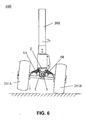
- the front wheel stem 202 is perpendicular to the front wheel supporting shaft 1, during turning, the front wheel stem 202 is rotated, so as to drive the connecting member 2 to rotate.
- the connecting member 2 drives the connecting shaft 21 to swing towards the turning direction, then the connecting shaft 21 drives the front wheel supporting shaft 1 to swing.
- the front wheel supporting shaft 1 rotates in parallel to the ground, the first front wheel 201 A and the second front wheel 210B roll and turn without leaving the ground.
- the connecting member 2 is inclined along with the front wheel stem 202, and therefore, after the connecting member 2 rotates to drive the connecting shaft 21 to swing, one end of the front wheel supporting shaft 1 tilts with respect to the other end. Then, the front wheel supporting shaft 1 is no longer parallel to the ground but has one end tilted, and one of the front wheels 201 is driven by the front wheel supporting shaft 1 to tilt.
- the connecting shaft 21 is pivoted on the front wheel supporting shaft 1 through the bearings 3, and therefore, the tilted end of the front wheel supporting shaft 1 descends along an axis of the connecting shaft 21 under the action of gravity of the front wheel 201.
- the tilted front wheel 201 also descends along with the front wheel supporting shaft 1, such that the front wheel supporting shaft 1 keeps in parallel to the ground, thus enabling the front wheels 201 to roll and turn without leaving the ground.
- the bearings 3 are mounted at the middle portion of the front wheel supporting shaft 1, the connecting member 2 is sleeved on and fixed to the front wheel stem 202, and the connecting shaft 21 is sleeved on and fixed to the bearings 3, so that when the front wheel stem 202 rotates to swing the connecting shaft 21, the front wheel supporting shaft 1 is further driven to swing, thereby realizing turning.
- the front wheel supporting shaft 1 After the front wheel supporting shaft 1 swings, the front wheel supporting shaft 1 rotates along the connecting shaft 21 under the action of gravity of the front wheel 201, so as to enable the first front wheel 201A and the second front wheel 201 B to travel without leaving the ground, thereby preventing the first front wheel 201 A and the second front wheel 201 B from tilting to affect driving safety.
- the present invention has a simple structure and is convenient in use.
- the first shock absorber 4A and the second shock absorber 4B are disposed to enable the automatic wheel adjustment mechanism 100 to reduce the shock incurred by the front wheels 201 to the front wheel stem 202 when adjusting the front wheels 201 during turning, thereby making the driving more comfortable.
- the angle adjustment method of the front wheel stem 202 involved in the automatic wheel adjustment mechanism 100 according to the present invention is well known by those of ordinary skill in the art, and is not illustrated in detail.
Description
- The present invention relates to an adjustment mechanism, in particular, to an automatic wheel adjustment mechanism mounted between front wheels and a front wheel stem of an foldable motorized vehicle, for ensuring that both front wheels contact the ground while turning.
- Currently, for better use experience of drivers of different ages and different physical conditions, four-wheel motorized vehicle are mostly disposed with an angle adjustment mechanism between a front wheel stem and a body rack. The angle adjustment mechanism can be used by a driver to adjust the angle freely, so that every driver can hold the handle mounted on the front wheel stem when sitting on a seat to control the handle, meeting requirements of different users, and being convenient in use.
- However, in the current four-wheel motorized vehicle, the two front wheels are generally fixedly connected to the front wheel stem directly, and when the front wheel stem is in a vertical state, the driver can normally control the driving direction of the two front wheels when rotating the front wheel stem to the left or the right. However, when the driver adjusts the front wheel stem to an angle through the angle adjustment mechanism, the front wheel stem assumes an inclined state with respect to that before the adjustment, so when the electric vehicle turns and the front wheel stem is rotated through the handle, the front wheel stem drives an axle of the two front wheels to swing, thus causing one of the two front wheels tilts with respect to the other one. The tilted front wheel cannot travel without leaving the ground, which has a great impact on the driving safety during turning, and the technology used in the current motorized vehicle is unable to solve the above problem.
- Therefore, a heretofore unaddressed need exists in the art to address the aforementioned deficiencies and inadequacies.
- A scooter with two steerable front wheels and an automatic wheel adjustment mechanism according to the preamble of
claim 1 is known fromGB 2 367 541 A - The present invention provides an automatic wheel adjustment mechanism having a simple structure and capable of preventing the front wheels of a motorized vehicle from tilting to affect driving safety, as is defined in
claim 1. - Preferred embodiments are defined in the dependent claims. Further, the invention provides according to claims 7 and 8 a foldable motorized vehicle having such an automatic wheel adjustment mechanism.
- These and other aspects of the present invention will become apparent from the following description of the preferred embodiment taken in conjunction with the following drawings, although variations and modifications therein may be affected without departing from the scope of the appended claims.
- Further features and benefits of the present invention will be apparent from a detailed description of preferred embodiments thereof taken in conjunction with the following drawings, wherein similar elements are referred to with similar reference numbers, and wherein:
-
FIG. 1 is an abbreviated perspective view of a foldable motorized vehicle according one embodiment of the present invention; -
FIG. 2 is an perspective view of an automatic wheel adjustment mechanism according to one embodiment of the present invention; -
FIG. 3 is an exploded perspective view of the automatic wheel adjustment mechanism according to one embodiment of the present invention; -
FIG. 4 is a perspective view of a connecting member in the automatic wheel adjustment mechanism according to one embodiment of the present invention; -
FIG. 5 is a perspective view of a shock absorber in the automatic wheel adjustment mechanism according to one embodiment of the present invention; -
FIG. 6 is a front illustration of the automatic wheel adjustment mechanism when the front wheels were turned according to one embodiment of the present invention; and -
FIG. 7 is a front view of the automatic wheel adjustment mechanism after the wheels automatically adjustment according to one embodiment of the present invention. - The present invention is more particularly described in the following examples that are intended as illustrative only since numerous modifications and variations therein will be apparent to those skilled in the art. Various embodiments of the invention are now described in detail. Referring to the drawings, like numbers indicate like components throughout the views.
- The terms used in this specification generally have their ordinary meanings in the art, within the context of the disclosure, and in the specific context where each term is used. Certain terms that are used to describe the disclosure are discussed below, or elsewhere in the specification, to provide additional guidance to the practitioner regarding the description of the disclosure. The use of examples anywhere in this specification, including examples of any terms discussed herein, is illustrative only, and in no way limits the scope and meaning of the disclosure or of any exemplified term. Likewise, the disclosure is not limited to various embodiments given in this specification.
- As used herein, "around", "about" or "approximately" shall generally mean within 20 percent, preferably within 10 percent, and more preferably within 5 percent of a given value or range. Numerical quantities given herein are approximate, meaning that the term "around", "about" or "approximately" can be inferred if not expressly stated.
- As used herein, the terms "comprising," "including," "having," "containing," "involving," and the like are to be understood to be open-ended, i.e., to mean including but not limited to.
- Embodiments of the present invention are described below with reference to the accompanying drawings, and in the accompanying drawings like reference numerals represent like elements.
- Referring now to
FIG. 1 , a perspective view of a foldable motorized vehicle is shown according one embodiment of the present invention. The foldable motorized vehicle has: (a) afoldable frame body 20, (b) a foldableseat mounting rack 10, (c) aseat 30, (d) a frontwheel steering mechanism 100, and (e)handlebar folding mechanism 40 with two foldable handlebars, and a steeringaxial rod 200. As it is shown inFIG. 1 , the seat, the frame body, and steering are all foldable so that the entire vehicle is foldable to save storage space. -
FIG. 2 offers a closer and detailed view of the automaticwheel adjustment mechanism 100 of the foldable motorized vehicle according to one embodiment of the present invention. Referring now toFIG. 3 , an exploded perspective view of the automatic wheel adjustment mechanism is shown according to one embodiment of the present invention. In one embodiment, the automatic wheel adjustment mechanism includes: (a) a frontwheel supporting shaft 1, (b) a connectingmember 2, and (c) a plurality ofbearings 3. The frontwheel supporting shaft 1 has afirst end 1A , asecond end 1 B, a bearinghousing 11 positioned on the top center portion of the frontwheel supporting shaft 1, a first connectingportion 12A positioned on afirst end 1A of the frontwheel supporting shaft 1, and a second connectingportion 12B positioned on asecond end 1 B of the frontwheel supporting shaft 1. - As shown in
FIG. 4 , in one embodiment, the connectingmember 2 has a ring shapedbody 22 on a first end and a connectingshaft 21 on a second end. The connectingshaft 21 extends upwards to form a connectingportion 21 a. The plurality of thebearings 3 are mounted inside of the bearinghousing 11 of the frontwheel supporting shaft 1. - The first
front wheel 201A is mounted on thefirst end 1A of the frontwheel supporting shaft 1, and the secondfront wheel 201 B is mounted on thesecond end 1 B of the frontwheel supporting shaft 1. - The lower end of the
front wheel stem 202 is inserted into the ringshaped body 22 of the connectingmember 2 and is fixed onto the ringshaped body 22 of the connectingmember 2. - The connecting
shaft 21 of the connectingmember 2 is perpendicular to the ringshaped body 22 of the connectingmember 2 and protrudes forward from the connectingmember 2, and mounted inside of the inner races of the plurality of thebearings 3. - Referring to
FIG. 5 , the automaticwheel adjustment mechanism 100 further includes afirst shock absorber 4A and a second shock absorber 4B. Each of the first and second shock absorbers comprises afirst end portion 41, asecond end portion 42, and anelastic element 43. Theelastic element 43 is disposed obliquely between thefirst end portion 41, and thesecond end portion 42 of the first and second shock absorbers. - The
first end portion 41 of thefirst shock absorber 4A is connected to the connectingportion 21 a of the connectingmember 2. Thesecond end portion 42 of thefirst shock absorber 4A is connected to the first connectingportion 12A of the frontwheel supporting shaft 1. Thefirst end portion 41 of thesecond shock absorber 4B is connected to the connectingportion 21 a of the connectingmember 2. Thesecond end portion 42 is connected to the second connectingportion 12B of the frontwheel supporting shaft 1. - The
elastic element 43 of the first shock absorber 4A and thesecond shock absorber 4B are coil springs. Theelastic element 43 of the first shock absorber 4A and thesecond shock absorber 4B are placed on two sides of the connectingshaft 21 of the connectingmember 2, symmetrically, in a shape of two splayed legs. - In view of the above and referring to
FIG. 6 andFIG. 7 , thefront wheel stem 202 is perpendicular to the frontwheel supporting shaft 1, during turning, thefront wheel stem 202 is rotated, so as to drive the connectingmember 2 to rotate. The connectingmember 2 drives the connectingshaft 21 to swing towards the turning direction, then the connectingshaft 21 drives the frontwheel supporting shaft 1 to swing. At this time, the frontwheel supporting shaft 1 rotates in parallel to the ground, the firstfront wheel 201 A and the second front wheel 210B roll and turn without leaving the ground. After thefront wheel stem 202 is adjusted to be inclined, during turning, thefront wheel stem 202 is rotated, so as to drive the connectingmember 2 to rotate, the connectingmember 2 is inclined along with thefront wheel stem 202, and therefore, after the connectingmember 2 rotates to drive the connectingshaft 21 to swing, one end of the frontwheel supporting shaft 1 tilts with respect to the other end. Then, the frontwheel supporting shaft 1 is no longer parallel to the ground but has one end tilted, and one of the front wheels 201 is driven by the frontwheel supporting shaft 1 to tilt. The connectingshaft 21 is pivoted on the frontwheel supporting shaft 1 through thebearings 3, and therefore, the tilted end of the frontwheel supporting shaft 1 descends along an axis of the connectingshaft 21 under the action of gravity of the front wheel 201. The tilted front wheel 201 also descends along with the frontwheel supporting shaft 1, such that the frontwheel supporting shaft 1 keeps in parallel to the ground, thus enabling the front wheels 201 to roll and turn without leaving the ground. - Compared with the prior art, in the present invention, the
bearings 3 are mounted at the middle portion of the frontwheel supporting shaft 1, the connectingmember 2 is sleeved on and fixed to thefront wheel stem 202, and the connectingshaft 21 is sleeved on and fixed to thebearings 3, so that when the front wheel stem 202 rotates to swing the connectingshaft 21, the frontwheel supporting shaft 1 is further driven to swing, thereby realizing turning. After the frontwheel supporting shaft 1 swings, the frontwheel supporting shaft 1 rotates along the connectingshaft 21 under the action of gravity of the front wheel 201, so as to enable the firstfront wheel 201A and the secondfront wheel 201 B to travel without leaving the ground, thereby preventing the firstfront wheel 201 A and the secondfront wheel 201 B from tilting to affect driving safety. The present invention has a simple structure and is convenient in use. In addition, thefirst shock absorber 4A and thesecond shock absorber 4B are disposed to enable the automaticwheel adjustment mechanism 100 to reduce the shock incurred by the front wheels 201 to the front wheel stem 202 when adjusting the front wheels 201 during turning, thereby making the driving more comfortable. - The angle adjustment method of the front wheel stem 202 involved in the automatic
wheel adjustment mechanism 100 according to the present invention is well known by those of ordinary skill in the art, and is not illustrated in detail. - The foregoing description of the exemplary embodiments of the invention has been presented only for the purposes of illustration and description and is not intended to be exhaustive or to limit the invention to the precise forms disclosed. Many modifications and variations are possible in light of the above teaching.
- The embodiments were chosen and described in order to explain the principles of the invention and their practical application so as to activate others skilled in the art to utilize the invention and various embodiments and with various modifications as are suited to the particular use contemplated. Alternative embodiments will become apparent to those skilled in the art to which the present invention pertains. Accordingly, the scope of the present invention is defined by the appended claims rather than the foregoing description and the exemplary embodiments described therein.
Claims (9)
- An automatic wheel adjustment mechanism mountable between a first front wheel (201 A) and a second front wheel (201 B) and a front wheel stem (202) of a foldable motorized vehicle, comprising:(a) a front wheel supporting shaft (1) having a first end (1A), a second end (1 B), a bearing housing (11) positioned on the top center portion of the front wheel supporting shaft, a first connecting portion (12A) positioned on a first end of the front wheel supporting shaft, and a second connecting portion (12B) positioned on a second end of the front wheel supporting shaft;(b) a connecting member (2) having a ring shaped body (22) on a first end and a connecting shaft (21) on a second end,
characterized in that the connecting shaft (21) protrudes forward from the ring shaped body (22) and has a connecting portion (21a) which extends upwards from the connecting shaft (21), and that the automatic wheel adjustment mechanism further comprises:(c) a plurality of bearings (3) mounted inside of the bearing housing (11),
wherein outer races of the plurality of the bearings (3) are fixed at the center portion of the front wheel supporting shaft (1) inside of the bearing housing (11), the ring shaped body (22) of the connecting member (2) is connectable to the lower end of the front wheel stem (20), the connecting shaft (21) of the connecting member passes through and fixedly connected to the inner races of the plurality of the bearings (3). - The automatic wheel adjustment mechanism according to claim 1, wherein the first front wheel (201A) is mounted on the first end (1A) of the front wheel supporting shaft (1), and the second front wheel (201 B) is mounted on the second end (1 B) of the front wheel supporting shaft (1).
- The automatic wheel adjustment mechanism according to claim 2, wherein the lower end of the front wheel stem (202) is inserted into the ring shaped body (22) of the connecting member (2) and is fixed onto the ring shaped body (22) of the connecting member (2).
- The automatic wheel adjustment mechanism according to claim 3, wherein the connecting shaft (21) of the connecting member (2) is perpendicular to the ring shaped body (22) of the connecting member (2) and is mounted inside of the inner races of the plurality of the bearings (3).
- The automatic wheel adjustment mechanism according to claim 4, wherein the automatic wheel adjustment mechanism further comprises a first shock absorber (4A) and a second shock absorber (4B), each of the first and second shock absorbers comprises a first end portion (41), a second end portion (42), and an elastic element (43), the elastic element is disposed obliquely between the first end portion (41) and the second end portion (42) of the first and second shock absorbers.
- The automatic wheel adjustment mechanism according to claim 5, wherein the first end portion (41) of the first shock absorber (4A) is connected to the connecting portion (21 a) of the connecting member (2), the second end portion (42) of the first shock absorber (4A) is connected to the first connecting portion (12A) of the front wheel supporting shaft (21), the first end portion (42) of the second shock absorber (4B) is connected to the connecting portion (21 a) of the connecting member (2), and the second end portion (42) is connected to the second connecting portion (12B) of the front wheel supporting shaft (21).
- The automatic wheel adjustment mechanism according to claim 6, wherein the elastic element (43) of the first shock absorber (4A) and the second shock absorber (4B) comprises a coil spring, and the elastic element (43) of the first shock absorber (4A) and the second shock absorber (4B) are placed on two sides of the connecting shaft (21) of the connecting member (2), symmetrically, in a shape of two splayed legs.
- A foldable motorized vehicle, comprising:a first front wheel (201 A);a second front wheel (201 B);a front wheel stem (202); andan automatic wheel adjustment mechanism according to claim 1 mounted between the first front wheel (201A) and the second front wheel (201 B) and the front wheel stem (202).
- The foldable motorized vehicle of claim 8, having the automatic wheel adjustment mechanism of one of claims 2 to 7.
Applications Claiming Priority (3)
| Application Number | Priority Date | Filing Date | Title |
|---|---|---|---|
| CN2011200298578U CN202029936U (en) | 2011-01-28 | 2011-01-28 | Mounting support |
| CN2011200298366U CN201989907U (en) | 2011-01-28 | 2011-01-28 | Automatic regulation mechanism for wheel |
| US13/357,247 US8511705B2 (en) | 2011-01-28 | 2012-01-24 | Wheel automatic adjustment mechanism and foldable motorized vehicle having same |
Publications (3)
| Publication Number | Publication Date |
|---|---|
| EP2481659A2 EP2481659A2 (en) | 2012-08-01 |
| EP2481659A3 EP2481659A3 (en) | 2013-10-09 |
| EP2481659B1 true EP2481659B1 (en) | 2015-03-11 |
Family
ID=45497908
Family Applications (1)
| Application Number | Title | Priority Date | Filing Date |
|---|---|---|---|
| EP20120152670 Active EP2481659B1 (en) | 2011-01-28 | 2012-01-26 | Wheel automatic adjustment mechanism and foldable motorized vehicle having same |
Country Status (1)
| Country | Link |
|---|---|
| EP (1) | EP2481659B1 (en) |
Families Citing this family (3)
| Publication number | Priority date | Publication date | Assignee | Title |
|---|---|---|---|---|
| CN104890780A (en) * | 2014-03-03 | 2015-09-09 | 李玉新 | Wheel chair type multifunctional electric vehicle with or without steering wheel |
| EP3403908A1 (en) * | 2017-05-18 | 2018-11-21 | KUIANDA Company Limited | Shock-absorbent anti-tilt structure of electric carrier |
| EP3403858A1 (en) * | 2017-05-18 | 2018-11-21 | KUIANDA Company Limited | Shock-absorbent structure of electric carrier |
Family Cites Families (9)
| Publication number | Priority date | Publication date | Assignee | Title |
|---|---|---|---|---|
| JPS55102714A (en) * | 1979-01-31 | 1980-08-06 | Suzuki Motor Co Ltd | Front two-wheel suspension system for four-wheel vehicle |
| US5630774A (en) * | 1992-07-27 | 1997-05-20 | Geschwender; Robert C. | Exercise technique and apparatus |
| US6299186B1 (en) * | 2000-04-28 | 2001-10-09 | Chuan-Fu Kao | Antishock structure of scooter |
| GB2367541A (en) * | 2000-10-05 | 2002-04-10 | Lai Huei Chen | Scooter with two steerable front wheels |
| US20020125709A1 (en) * | 2001-03-08 | 2002-09-12 | Wu Donald P.H. | Articulated front axle assembly for electric three-wheeled invalid power chair |
| US6565105B2 (en) * | 2001-10-09 | 2003-05-20 | Samuel Lin | Frame for an electric scooter |
| US7029016B2 (en) * | 2003-09-16 | 2006-04-18 | Sunpex Technology Co., Ltd. | Shock absorbing structure of turning mechanism of an electric cart equipped with twin front wheels |
| US7226081B2 (en) * | 2005-02-28 | 2007-06-05 | Far Great Plastics Industrial Co., Ltd. | Steering knuckle structure |
| US20100013183A1 (en) * | 2008-07-18 | 2010-01-21 | Rurong He | Three wheeled scooter |
-
2012
- 2012-01-26 EP EP20120152670 patent/EP2481659B1/en active Active
Also Published As
| Publication number | Publication date |
|---|---|
| EP2481659A2 (en) | 2012-08-01 |
| EP2481659A3 (en) | 2013-10-09 |
Similar Documents
| Publication | Publication Date | Title |
|---|---|---|
| US8104781B2 (en) | Wheeled tilting apparatus | |
| US8123240B2 (en) | Control system for leaning vehicle | |
| US20110233885A1 (en) | Lean-steering stabilization device for a vehicle having a leaning part and a non-leaning part | |
| JP2007061342A (en) | Electric six-wheeled chair | |
| EP2481659B1 (en) | Wheel automatic adjustment mechanism and foldable motorized vehicle having same | |
| CN206797565U (en) | Tilting positive three-wheeled motor vehicle can brake type leaning device | |
| CN104271434A (en) | Vehicle having positional control function | |
| US8511705B2 (en) | Wheel automatic adjustment mechanism and foldable motorized vehicle having same | |
| US9227685B2 (en) | Vehicle | |
| JP2016513595A (en) | Complete machine control for tilt control of vehicles with at least three wheels | |
| JP5279922B2 (en) | Suspension system for saddle-ride type vehicles | |
| US8973695B2 (en) | Vehicle wheeled device | |
| JP2012096703A (en) | Suspension apparatus | |
| US10899383B2 (en) | Control unit that adjusts a tilt angle of a tilting vehicle | |
| KR102299340B1 (en) | Driving mode changeable small mobility | |
| US20220331686A1 (en) | Skateboard suspension | |
| WO2014174140A1 (en) | Vehicle | |
| KR20140073134A (en) | Vehicle body stability control device | |
| NL1035799C2 (en) | Tiltable tricycle, has left outer tubular member and right tubular member respectively and pivotally connected to another left outer tubular member and another right tubular member by hinge | |
| JP2003112511A (en) | Front suspension device | |
| CN215245325U (en) | Electric tricycle steering device with high pressure bearing capacity | |
| WO2017161532A1 (en) | Electric self-balancing scooter | |
| KR20080010120A (en) | Turning stablity apparatus for vehicles | |
| GB2551222B (en) | Slot guided motorcycle | |
| CN111231597A (en) | Anti-roll bar device and wheel anti-roll system |
Legal Events
| Date | Code | Title | Description |
|---|---|---|---|
| PUAI | Public reference made under article 153(3) epc to a published international application that has entered the european phase |
Free format text: ORIGINAL CODE: 0009012 |
|
| AK | Designated contracting states |
Kind code of ref document: A2 Designated state(s): AL AT BE BG CH CY CZ DE DK EE ES FI FR GB GR HR HU IE IS IT LI LT LU LV MC MK MT NL NO PL PT RO RS SE SI SK SM TR |
|
| AX | Request for extension of the european patent |
Extension state: BA ME |
|
| PUAL | Search report despatched |
Free format text: ORIGINAL CODE: 0009013 |
|
| AK | Designated contracting states |
Kind code of ref document: A3 Designated state(s): AL AT BE BG CH CY CZ DE DK EE ES FI FR GB GR HR HU IE IS IT LI LT LU LV MC MK MT NL NO PL PT RO RS SE SI SK SM TR |
|
| AX | Request for extension of the european patent |
Extension state: BA ME |
|
| RIC1 | Information provided on ipc code assigned before grant |
Ipc: B62K 5/00 20130101AFI20130905BHEP Ipc: B62K 5/08 20060101ALI20130905BHEP |
|
| RAP1 | Party data changed (applicant data changed or rights of an application transferred) |
Owner name: DONGGUAN PRESTIGE SPORTING PRODUCTS CO., LTD. |
|
| 17P | Request for examination filed |
Effective date: 20140409 |
|
| RBV | Designated contracting states (corrected) |
Designated state(s): AL AT BE BG CH CY CZ DE DK EE ES FI FR GB GR HR HU IE IS IT LI LT LU LV MC MK MT NL NO PL PT RO RS SE SI SK SM TR |
|
| GRAP | Despatch of communication of intention to grant a patent |
Free format text: ORIGINAL CODE: EPIDOSNIGR1 |
|
| RIC1 | Information provided on ipc code assigned before grant |
Ipc: B62K 5/007 20130101ALI20140829BHEP Ipc: B62K 5/00 20130101AFI20140829BHEP Ipc: B60G 11/14 20060101ALI20140829BHEP Ipc: B62K 5/08 20060101ALI20140829BHEP Ipc: B60G 9/02 20060101ALI20140829BHEP |
|
| INTG | Intention to grant announced |
Effective date: 20140916 |
|
| GRAS | Grant fee paid |
Free format text: ORIGINAL CODE: EPIDOSNIGR3 |
|
| GRAA | (expected) grant |
Free format text: ORIGINAL CODE: 0009210 |
|
| AK | Designated contracting states |
Kind code of ref document: B1 Designated state(s): AL AT BE BG CH CY CZ DE DK EE ES FI FR GB GR HR HU IE IS IT LI LT LU LV MC MK MT NL NO PL PT RO RS SE SI SK SM TR |
|
| REG | Reference to a national code |
Ref country code: GB Ref legal event code: FG4D |
|
| REG | Reference to a national code |
Ref country code: CH Ref legal event code: EP |
|
| REG | Reference to a national code |
Ref country code: ES Ref legal event code: FG2A Ref document number: 2532930 Country of ref document: ES Kind code of ref document: T3 Effective date: 20150406 |
|
| REG | Reference to a national code |
Ref country code: IE Ref legal event code: FG4D |
|
| REG | Reference to a national code |
Ref country code: AT Ref legal event code: REF Ref document number: 715147 Country of ref document: AT Kind code of ref document: T Effective date: 20150415 |
|
| REG | Reference to a national code |
Ref country code: DE Ref legal event code: R096 Ref document number: 602012005760 Country of ref document: DE Effective date: 20150423 |
|
| REG | Reference to a national code |
Ref country code: NL Ref legal event code: T3 |
|
| PG25 | Lapsed in a contracting state [announced via postgrant information from national office to epo] |
Ref country code: LT Free format text: LAPSE BECAUSE OF FAILURE TO SUBMIT A TRANSLATION OF THE DESCRIPTION OR TO PAY THE FEE WITHIN THE PRESCRIBED TIME-LIMIT Effective date: 20150311 Ref country code: HR Free format text: LAPSE BECAUSE OF FAILURE TO SUBMIT A TRANSLATION OF THE DESCRIPTION OR TO PAY THE FEE WITHIN THE PRESCRIBED TIME-LIMIT Effective date: 20150311 Ref country code: NO Free format text: LAPSE BECAUSE OF FAILURE TO SUBMIT A TRANSLATION OF THE DESCRIPTION OR TO PAY THE FEE WITHIN THE PRESCRIBED TIME-LIMIT Effective date: 20150611 Ref country code: SE Free format text: LAPSE BECAUSE OF FAILURE TO SUBMIT A TRANSLATION OF THE DESCRIPTION OR TO PAY THE FEE WITHIN THE PRESCRIBED TIME-LIMIT Effective date: 20150311 Ref country code: FI Free format text: LAPSE BECAUSE OF FAILURE TO SUBMIT A TRANSLATION OF THE DESCRIPTION OR TO PAY THE FEE WITHIN THE PRESCRIBED TIME-LIMIT Effective date: 20150311 |
|
| REG | Reference to a national code |
Ref country code: AT Ref legal event code: MK05 Ref document number: 715147 Country of ref document: AT Kind code of ref document: T Effective date: 20150311 |
|
| REG | Reference to a national code |
Ref country code: LT Ref legal event code: MG4D |
|
| PG25 | Lapsed in a contracting state [announced via postgrant information from national office to epo] |
Ref country code: GR Free format text: LAPSE BECAUSE OF FAILURE TO SUBMIT A TRANSLATION OF THE DESCRIPTION OR TO PAY THE FEE WITHIN THE PRESCRIBED TIME-LIMIT Effective date: 20150612 Ref country code: LV Free format text: LAPSE BECAUSE OF FAILURE TO SUBMIT A TRANSLATION OF THE DESCRIPTION OR TO PAY THE FEE WITHIN THE PRESCRIBED TIME-LIMIT Effective date: 20150311 Ref country code: RS Free format text: LAPSE BECAUSE OF FAILURE TO SUBMIT A TRANSLATION OF THE DESCRIPTION OR TO PAY THE FEE WITHIN THE PRESCRIBED TIME-LIMIT Effective date: 20150311 |
|
| PG25 | Lapsed in a contracting state [announced via postgrant information from national office to epo] |
Ref country code: EE Free format text: LAPSE BECAUSE OF FAILURE TO SUBMIT A TRANSLATION OF THE DESCRIPTION OR TO PAY THE FEE WITHIN THE PRESCRIBED TIME-LIMIT Effective date: 20150311 Ref country code: CZ Free format text: LAPSE BECAUSE OF FAILURE TO SUBMIT A TRANSLATION OF THE DESCRIPTION OR TO PAY THE FEE WITHIN THE PRESCRIBED TIME-LIMIT Effective date: 20150311 Ref country code: SK Free format text: LAPSE BECAUSE OF FAILURE TO SUBMIT A TRANSLATION OF THE DESCRIPTION OR TO PAY THE FEE WITHIN THE PRESCRIBED TIME-LIMIT Effective date: 20150311 Ref country code: PT Free format text: LAPSE BECAUSE OF FAILURE TO SUBMIT A TRANSLATION OF THE DESCRIPTION OR TO PAY THE FEE WITHIN THE PRESCRIBED TIME-LIMIT Effective date: 20150713 Ref country code: RO Free format text: LAPSE BECAUSE OF FAILURE TO SUBMIT A TRANSLATION OF THE DESCRIPTION OR TO PAY THE FEE WITHIN THE PRESCRIBED TIME-LIMIT Effective date: 20150311 |
|
| PG25 | Lapsed in a contracting state [announced via postgrant information from national office to epo] |
Ref country code: PL Free format text: LAPSE BECAUSE OF FAILURE TO SUBMIT A TRANSLATION OF THE DESCRIPTION OR TO PAY THE FEE WITHIN THE PRESCRIBED TIME-LIMIT Effective date: 20150311 Ref country code: AT Free format text: LAPSE BECAUSE OF FAILURE TO SUBMIT A TRANSLATION OF THE DESCRIPTION OR TO PAY THE FEE WITHIN THE PRESCRIBED TIME-LIMIT Effective date: 20150311 Ref country code: IS Free format text: LAPSE BECAUSE OF FAILURE TO SUBMIT A TRANSLATION OF THE DESCRIPTION OR TO PAY THE FEE WITHIN THE PRESCRIBED TIME-LIMIT Effective date: 20150711 |
|
| REG | Reference to a national code |
Ref country code: DE Ref legal event code: R097 Ref document number: 602012005760 Country of ref document: DE |
|
| PLBE | No opposition filed within time limit |
Free format text: ORIGINAL CODE: 0009261 |
|
| STAA | Information on the status of an ep patent application or granted ep patent |
Free format text: STATUS: NO OPPOSITION FILED WITHIN TIME LIMIT |
|
| REG | Reference to a national code |
Ref country code: FR Ref legal event code: PLFP Year of fee payment: 5 |
|
| PG25 | Lapsed in a contracting state [announced via postgrant information from national office to epo] |
Ref country code: DK Free format text: LAPSE BECAUSE OF FAILURE TO SUBMIT A TRANSLATION OF THE DESCRIPTION OR TO PAY THE FEE WITHIN THE PRESCRIBED TIME-LIMIT Effective date: 20150311 |
|
| 26N | No opposition filed |
Effective date: 20151214 |
|
| PG25 | Lapsed in a contracting state [announced via postgrant information from national office to epo] |
Ref country code: SI Free format text: LAPSE BECAUSE OF FAILURE TO SUBMIT A TRANSLATION OF THE DESCRIPTION OR TO PAY THE FEE WITHIN THE PRESCRIBED TIME-LIMIT Effective date: 20150311 |
|
| PG25 | Lapsed in a contracting state [announced via postgrant information from national office to epo] |
Ref country code: BE Free format text: LAPSE BECAUSE OF NON-PAYMENT OF DUE FEES Effective date: 20160131 |
|
| PG25 | Lapsed in a contracting state [announced via postgrant information from national office to epo] |
Ref country code: LU Free format text: LAPSE BECAUSE OF FAILURE TO SUBMIT A TRANSLATION OF THE DESCRIPTION OR TO PAY THE FEE WITHIN THE PRESCRIBED TIME-LIMIT Effective date: 20160126 Ref country code: BE Free format text: LAPSE BECAUSE OF FAILURE TO SUBMIT A TRANSLATION OF THE DESCRIPTION OR TO PAY THE FEE WITHIN THE PRESCRIBED TIME-LIMIT Effective date: 20150311 |
|
| REG | Reference to a national code |
Ref country code: CH Ref legal event code: PL |
|
| PG25 | Lapsed in a contracting state [announced via postgrant information from national office to epo] |
Ref country code: MC Free format text: LAPSE BECAUSE OF FAILURE TO SUBMIT A TRANSLATION OF THE DESCRIPTION OR TO PAY THE FEE WITHIN THE PRESCRIBED TIME-LIMIT Effective date: 20150311 |
|
| PG25 | Lapsed in a contracting state [announced via postgrant information from national office to epo] |
Ref country code: LI Free format text: LAPSE BECAUSE OF NON-PAYMENT OF DUE FEES Effective date: 20160131 Ref country code: CH Free format text: LAPSE BECAUSE OF NON-PAYMENT OF DUE FEES Effective date: 20160131 |
|
| REG | Reference to a national code |
Ref country code: IE Ref legal event code: MM4A |
|
| REG | Reference to a national code |
Ref country code: FR Ref legal event code: PLFP Year of fee payment: 6 |
|
| PG25 | Lapsed in a contracting state [announced via postgrant information from national office to epo] |
Ref country code: IE Free format text: LAPSE BECAUSE OF NON-PAYMENT OF DUE FEES Effective date: 20160126 |
|
| PG25 | Lapsed in a contracting state [announced via postgrant information from national office to epo] |
Ref country code: MT Free format text: LAPSE BECAUSE OF FAILURE TO SUBMIT A TRANSLATION OF THE DESCRIPTION OR TO PAY THE FEE WITHIN THE PRESCRIBED TIME-LIMIT Effective date: 20150311 |
|
| REG | Reference to a national code |
Ref country code: FR Ref legal event code: PLFP Year of fee payment: 7 |
|
| PG25 | Lapsed in a contracting state [announced via postgrant information from national office to epo] |
Ref country code: CY Free format text: LAPSE BECAUSE OF FAILURE TO SUBMIT A TRANSLATION OF THE DESCRIPTION OR TO PAY THE FEE WITHIN THE PRESCRIBED TIME-LIMIT Effective date: 20150311 Ref country code: HU Free format text: LAPSE BECAUSE OF FAILURE TO SUBMIT A TRANSLATION OF THE DESCRIPTION OR TO PAY THE FEE WITHIN THE PRESCRIBED TIME-LIMIT; INVALID AB INITIO Effective date: 20120126 Ref country code: SM Free format text: LAPSE BECAUSE OF FAILURE TO SUBMIT A TRANSLATION OF THE DESCRIPTION OR TO PAY THE FEE WITHIN THE PRESCRIBED TIME-LIMIT Effective date: 20150311 |
|
| PG25 | Lapsed in a contracting state [announced via postgrant information from national office to epo] |
Ref country code: MT Free format text: LAPSE BECAUSE OF FAILURE TO SUBMIT A TRANSLATION OF THE DESCRIPTION OR TO PAY THE FEE WITHIN THE PRESCRIBED TIME-LIMIT Effective date: 20160131 Ref country code: MK Free format text: LAPSE BECAUSE OF FAILURE TO SUBMIT A TRANSLATION OF THE DESCRIPTION OR TO PAY THE FEE WITHIN THE PRESCRIBED TIME-LIMIT Effective date: 20150311 Ref country code: TR Free format text: LAPSE BECAUSE OF FAILURE TO SUBMIT A TRANSLATION OF THE DESCRIPTION OR TO PAY THE FEE WITHIN THE PRESCRIBED TIME-LIMIT Effective date: 20150311 |
|
| PG25 | Lapsed in a contracting state [announced via postgrant information from national office to epo] |
Ref country code: BG Free format text: LAPSE BECAUSE OF FAILURE TO SUBMIT A TRANSLATION OF THE DESCRIPTION OR TO PAY THE FEE WITHIN THE PRESCRIBED TIME-LIMIT Effective date: 20150311 |
|
| PG25 | Lapsed in a contracting state [announced via postgrant information from national office to epo] |
Ref country code: AL Free format text: LAPSE BECAUSE OF FAILURE TO SUBMIT A TRANSLATION OF THE DESCRIPTION OR TO PAY THE FEE WITHIN THE PRESCRIBED TIME-LIMIT Effective date: 20150311 |
|
| REG | Reference to a national code |
Ref country code: DE Ref legal event code: R081 Ref document number: 602012005760 Country of ref document: DE Owner name: GUANGDONG PRESTIGE TECHNOLOGY CO., LTD., DONGG, CN Free format text: FORMER OWNER: DUNGGUAN PRESTIGE SPORTING PRODUCTS CO., LTD., DONGGUAN, GUANGDONG, CN |
|
| PGFP | Annual fee paid to national office [announced via postgrant information from national office to epo] |
Ref country code: FR Payment date: 20230125 Year of fee payment: 12 Ref country code: ES Payment date: 20230201 Year of fee payment: 12 |
|
| PGFP | Annual fee paid to national office [announced via postgrant information from national office to epo] |
Ref country code: IT Payment date: 20230221 Year of fee payment: 12 Ref country code: GB Payment date: 20230127 Year of fee payment: 12 Ref country code: DE Payment date: 20230127 Year of fee payment: 12 |
|
| PGFP | Annual fee paid to national office [announced via postgrant information from national office to epo] |
Ref country code: NL Payment date: 20230126 Year of fee payment: 12 |
|
| P01 | Opt-out of the competence of the unified patent court (upc) registered |
Effective date: 20230612 |
|
| PGFP | Annual fee paid to national office [announced via postgrant information from national office to epo] |
Ref country code: NL Payment date: 20240126 Year of fee payment: 13 |
|
| PGFP | Annual fee paid to national office [announced via postgrant information from national office to epo] |
Ref country code: ES Payment date: 20240201 Year of fee payment: 13 |