EP2481520A2 - Pallet conveying device of horizontal machining center - Google Patents
Pallet conveying device of horizontal machining center Download PDFInfo
- Publication number
- EP2481520A2 EP2481520A2 EP10819043A EP10819043A EP2481520A2 EP 2481520 A2 EP2481520 A2 EP 2481520A2 EP 10819043 A EP10819043 A EP 10819043A EP 10819043 A EP10819043 A EP 10819043A EP 2481520 A2 EP2481520 A2 EP 2481520A2
- Authority
- EP
- European Patent Office
- Prior art keywords
- carrier
- pallet
- transferring
- pinion
- cam follower
- Prior art date
- Legal status (The legal status is an assumption and is not a legal conclusion. Google has not performed a legal analysis and makes no representation as to the accuracy of the status listed.)
- Granted
Links
Images



Classifications
-
- B—PERFORMING OPERATIONS; TRANSPORTING
- B23—MACHINE TOOLS; METAL-WORKING NOT OTHERWISE PROVIDED FOR
- B23Q—DETAILS, COMPONENTS, OR ACCESSORIES FOR MACHINE TOOLS, e.g. ARRANGEMENTS FOR COPYING OR CONTROLLING; MACHINE TOOLS IN GENERAL CHARACTERISED BY THE CONSTRUCTION OF PARTICULAR DETAILS OR COMPONENTS; COMBINATIONS OR ASSOCIATIONS OF METAL-WORKING MACHINES, NOT DIRECTED TO A PARTICULAR RESULT
- B23Q7/00—Arrangements for handling work specially combined with or arranged in, or specially adapted for use in connection with, machine tools, e.g. for conveying, loading, positioning, discharging, sorting
-
- B—PERFORMING OPERATIONS; TRANSPORTING
- B23—MACHINE TOOLS; METAL-WORKING NOT OTHERWISE PROVIDED FOR
- B23Q—DETAILS, COMPONENTS, OR ACCESSORIES FOR MACHINE TOOLS, e.g. ARRANGEMENTS FOR COPYING OR CONTROLLING; MACHINE TOOLS IN GENERAL CHARACTERISED BY THE CONSTRUCTION OF PARTICULAR DETAILS OR COMPONENTS; COMBINATIONS OR ASSOCIATIONS OF METAL-WORKING MACHINES, NOT DIRECTED TO A PARTICULAR RESULT
- B23Q7/00—Arrangements for handling work specially combined with or arranged in, or specially adapted for use in connection with, machine tools, e.g. for conveying, loading, positioning, discharging, sorting
- B23Q7/14—Arrangements for handling work specially combined with or arranged in, or specially adapted for use in connection with, machine tools, e.g. for conveying, loading, positioning, discharging, sorting co-ordinated in production lines
- B23Q7/1426—Arrangements for handling work specially combined with or arranged in, or specially adapted for use in connection with, machine tools, e.g. for conveying, loading, positioning, discharging, sorting co-ordinated in production lines with work holders not rigidly fixed to the transport devices
- B23Q7/1431—Work holder changers
-
- B—PERFORMING OPERATIONS; TRANSPORTING
- B23—MACHINE TOOLS; METAL-WORKING NOT OTHERWISE PROVIDED FOR
- B23Q—DETAILS, COMPONENTS, OR ACCESSORIES FOR MACHINE TOOLS, e.g. ARRANGEMENTS FOR COPYING OR CONTROLLING; MACHINE TOOLS IN GENERAL CHARACTERISED BY THE CONSTRUCTION OF PARTICULAR DETAILS OR COMPONENTS; COMBINATIONS OR ASSOCIATIONS OF METAL-WORKING MACHINES, NOT DIRECTED TO A PARTICULAR RESULT
- B23Q1/00—Members which are comprised in the general build-up of a form of machine, particularly relatively large fixed members
- B23Q1/25—Movable or adjustable work or tool supports
- B23Q1/26—Movable or adjustable work or tool supports characterised by constructional features relating to the co-operation of relatively movable members; Means for preventing relative movement of such members
- B23Q1/262—Movable or adjustable work or tool supports characterised by constructional features relating to the co-operation of relatively movable members; Means for preventing relative movement of such members with means to adjust the distance between the relatively slidable members
-
- B—PERFORMING OPERATIONS; TRANSPORTING
- B23—MACHINE TOOLS; METAL-WORKING NOT OTHERWISE PROVIDED FOR
- B23Q—DETAILS, COMPONENTS, OR ACCESSORIES FOR MACHINE TOOLS, e.g. ARRANGEMENTS FOR COPYING OR CONTROLLING; MACHINE TOOLS IN GENERAL CHARACTERISED BY THE CONSTRUCTION OF PARTICULAR DETAILS OR COMPONENTS; COMBINATIONS OR ASSOCIATIONS OF METAL-WORKING MACHINES, NOT DIRECTED TO A PARTICULAR RESULT
- B23Q7/00—Arrangements for handling work specially combined with or arranged in, or specially adapted for use in connection with, machine tools, e.g. for conveying, loading, positioning, discharging, sorting
- B23Q7/02—Arrangements for handling work specially combined with or arranged in, or specially adapted for use in connection with, machine tools, e.g. for conveying, loading, positioning, discharging, sorting by means of drums or rotating tables or discs
-
- B—PERFORMING OPERATIONS; TRANSPORTING
- B23—MACHINE TOOLS; METAL-WORKING NOT OTHERWISE PROVIDED FOR
- B23Q—DETAILS, COMPONENTS, OR ACCESSORIES FOR MACHINE TOOLS, e.g. ARRANGEMENTS FOR COPYING OR CONTROLLING; MACHINE TOOLS IN GENERAL CHARACTERISED BY THE CONSTRUCTION OF PARTICULAR DETAILS OR COMPONENTS; COMBINATIONS OR ASSOCIATIONS OF METAL-WORKING MACHINES, NOT DIRECTED TO A PARTICULAR RESULT
- B23Q7/00—Arrangements for handling work specially combined with or arranged in, or specially adapted for use in connection with, machine tools, e.g. for conveying, loading, positioning, discharging, sorting
- B23Q7/08—Arrangements for handling work specially combined with or arranged in, or specially adapted for use in connection with, machine tools, e.g. for conveying, loading, positioning, discharging, sorting by means of slides or chutes
-
- B—PERFORMING OPERATIONS; TRANSPORTING
- B23—MACHINE TOOLS; METAL-WORKING NOT OTHERWISE PROVIDED FOR
- B23Q—DETAILS, COMPONENTS, OR ACCESSORIES FOR MACHINE TOOLS, e.g. ARRANGEMENTS FOR COPYING OR CONTROLLING; MACHINE TOOLS IN GENERAL CHARACTERISED BY THE CONSTRUCTION OF PARTICULAR DETAILS OR COMPONENTS; COMBINATIONS OR ASSOCIATIONS OF METAL-WORKING MACHINES, NOT DIRECTED TO A PARTICULAR RESULT
- B23Q7/00—Arrangements for handling work specially combined with or arranged in, or specially adapted for use in connection with, machine tools, e.g. for conveying, loading, positioning, discharging, sorting
- B23Q7/14—Arrangements for handling work specially combined with or arranged in, or specially adapted for use in connection with, machine tools, e.g. for conveying, loading, positioning, discharging, sorting co-ordinated in production lines
-
- Y—GENERAL TAGGING OF NEW TECHNOLOGICAL DEVELOPMENTS; GENERAL TAGGING OF CROSS-SECTIONAL TECHNOLOGIES SPANNING OVER SEVERAL SECTIONS OF THE IPC; TECHNICAL SUBJECTS COVERED BY FORMER USPC CROSS-REFERENCE ART COLLECTIONS [XRACs] AND DIGESTS
- Y10—TECHNICAL SUBJECTS COVERED BY FORMER USPC
- Y10T—TECHNICAL SUBJECTS COVERED BY FORMER US CLASSIFICATION
- Y10T29/00—Metal working
- Y10T29/51—Plural diverse manufacturing apparatus including means for metal shaping or assembling
- Y10T29/5196—Multiple station with conveyor
Definitions
- the present invention relates to a multi pallet station of a horizontal type machine tool, and more particularly, to an apparatus capable of achieving a cost saving effect while significantly improving operational reliability as a structure of supporting a linear shaft of a pallet transferring apparatus (carrier) adopted in the horizontal type machine tool.
- a multi pallet station In recent years, in a horizontal type machine tool, a multi pallet station has been used to effectively receive a plurality of pallets and facilitate discharging of the plurality of pallets.
- a pallet transferring apparatus for moving forward and backward the pallet loading a workpiece is required, and in the related art, a ball screw and an LM guide are used to move forward/backward the pallet and a hydraulic cylinder is used to move up and down the pallet.
- rotational force generated from a servo motor 2 is converted into linear reciprocation transferring movement by a ball screw 3 and a horizontal LM guide 4 guides linear reciprocation movement of the carrier 1 in order to move forward/backward the carrier 1.
- the reason for using the ball screw 3 in moving forward/backward the carrier 1 is to ensure positional precision for accurately seating a pallet P at an accurate position in an equipment.
- Upward and downward movements of the carrier 1 are implemented by using a hydraulic cylinder 8 and a vertical LM guide 5.
- the hydraulic cylinder 8 is used.
- a roll cover 9 is attached to the horizontal LM guide 4 for supporting forward/backward movements of the carrier 1 for protection from a chip and a coolant.
- the pallet transferring apparatus in the related art has the following problems.
- the carrier 1 is fixed to the ball screw 3 and the carrier 1 has the same shape regardless of the size and the type (ex.: 400-grade HMC equipment to 800-grade HMC equipment) of the equipment. Therefore, when the equipment is upsized, an allowable load and a size of the workpiece also increase. When the equipment is upsized, capacities of the LM guides 4 and 5, the ball screw 3, and the hydraulic cylinder 8, that support the load during forward and backward movements and upward and downward movements, increase, and as a result, a main structure becomes bigger again.
- the roll cover 9 since an installation space of the roll cover 9 for protecting the LM guide 4 is small, the roll cover 9 is primarily used due to the constraint, but when the roll cover 9 is exposed to cutting oil with high toxicity for a long time, the roll cover 9 cannot have its own shape like a case in which roll cover 9 is wrinkled and the entirety of the roll cover 9 should be replaced frequently due to a limit in durability of an internal spring of the roll cover 9 taking charge of tightening and releasing.
- the present invention is contrived to solve the above-described problems in the related art and an object of the present invention is to provide a pallet transferring apparatus capable of minimizing a prime cost rise factor caused due to an increase in size of a pallet while maintaining positional precision of a ball screw and an LM guide which is a linear reciprocation moving means of a carrier of a pallet transferring apparatus for a horizontal type machine tool in the related art.
- Another object of the present invention is to provide a pallet transferring apparatus capable of ensuring the same positional precision when a carrier performs linear reciprocation movement as a more simple structure than the ball screw and the LM guide in the related art.
- yet another object of the present invention is to provide a cover means capable of increasing durability and apparatus reliability as compared with a roll cover in the related art.
- a pallet (P) transferring apparatus of a horizontal type machine tool adopts pinion/rack and cam follower structures instead of a ball screw and an LM guide in the related art in order to horizontally and reciprocatively transfer a carrier.
- the pallet (P) transferring apparatus of a horizontal type machine tool includes: a carrier 10 transferring a pallet P; a servo motor 20; a decelerator 30 decelerating rotational force received from the servo motor 20 and increasing torque; a pinion 40 converting the rotational force into linear reciprocation movement of the carrier 10 when the pinion 40 is installed on the side of the carrier 10 and receives the rotational force; a rack 50 engaging with the pinion 40 and transferring the rotational force received from the decelerator 30 to the pinion 40; and a cam follower 60 guiding forward and backward reciprocation transferring of the carrier 10.
- the pallet (P) transferring apparatus of a horizontal type machine tool may further include: a pivot means 70 rotatably fixing a rotational shaft B with respect to a fixation shaft A parallel to a horizontal plane; and a rotating means 80 varying an angle between the carrier 10 on the rotational shaft B and the horizontal plane by rotating the rotational shaft B around the center of the pivot means 70, preferably a hydraulic cylinder. Therefore, since the pallet (P) transferring apparatus may be configured by one fixation shaft and one rotational shaft, a pallet receiving structure is simplified as compared with the structure in the related art which receives the pallet along two vertical/horizontal fixation shafts.
- the pallet (P) transferring apparatus of a horizontal type machine tool may further include a slide cover 90 for protecting the carrier 10 from impurities according to a linear reciprocation transferring position of the carrier 10.
- the cam follower 60 may include: a first cam follower 61 which is eccentric to fix the top and the bottom of the carrier 10 simultaneously; and a second cam follower 62 for preventing horizontal swing of the carrier 10.
- a rack/pinion and a cam follower are adopted instead of a ball screw and an LM guide in the related art as a linear reciprocation transferring means of a carrier, such that the same precision is implemented without reducing positional precision which was an advantage of a structure in the related art while remarkably reducing an increase in cost due to an increase in size of an apparatus.
- the rack/pinion and the cam follower are adopted and a pivot means is adopted instead of the ball screw and the LM guide in the related art, such that the number of constituent components decreases and the structure is simplified, thereby saving a prime cost and even contributing to shortening a working time when a service is generated.
- a multistep slide cover of which the length is extensible is adopted instead of the roll cover in the related art to be adaptable to a change in length depending on the linear reciprocation transferring of the carrier, even impurity preventing performance and durability are epochally improved as compared with the roll cover in the related art, and reliability of the entire equipment is improved.
- FIG. 3 is a perspective view of a pallet transferring apparatus according to the present invention
- FIGS. 4 and 5 are detailed perspective views of the pallet transferring apparatus according to the present invention
- FIGS. 6 and 7 are side views of the pallet transferring apparatus according to the present invention.
- a pallet (P) transferring apparatus of a horizontal type machine tool includes a carrier 10, a servo motor 20, a decelerator 30, a pinion 40, a rack 50, and a cam follower 60, and the pinion 40, the rack 50, and the cam follower 60 replace roles of a ball screw and an LM guide in the related art.
- the carrier 10 as a means transferring a pallet P with the pallet P mounted thereon includes cam guide surfaces (not shown) on both sides, which engage with the cam follower 60 to be described below during forward and backward reciprocation transferring to guide forward and backward reciprocation transferring.
- the servo motor 20 generates driving force for forward and backward transferring movement of the carrier 10.
- the decelerator 30 is connected to the servo motor 20 in series to serve to decelerate rotational force received from the servo motor 20 and increase torque.
- the pinion 40 When the pinion 40 is installed on the side of the carrier 10 and receives rotational force from a predetermined power source, the pinion 40 converts the received rotational force into linear movement to enable the carrier 10 to reciprocate linearly.
- the rack 50 is connected to the decelerator 30 to transfer the rotational force received from the decelerator 30 to the pinion 40. That is, the rack 50 transfers rotational movement received through the servo motor 20 and the decelerator 30 to the pinion 40 and the pinion 40 converts the received rotational movement into linear reciprocating movement and the carrier 10 coupled to the pinion 40 performs linear reciprocation transferring movement together with the pinion 40.
- the cam follower 60 as a means for guiding forward and backward reciprocating transferring of the carrier 10 is fixed and disposed in plural at a predetermined interval along a forward/backward reciprocation transferring path of the carrier 10 outside both sides of the carrier 10.
- each cam follower 60 may be concentric, but is preferably eccentric to effectively fix both the top and the bottom of the carrier 10. That is, the cam follower 60 which is eccentric slightly upward based on a center line of a reciprocation transferring path of the carrier 10 in order to fix the top of the carrier 10 and the cam follower 60 which is eccentric slightly downward based on a center line of the reciprocation transferring path of the carrier 10 in order to fix the bottom of the carrier 10 are alternately disposed, such that the cam followers 60 may be disposed in a sort of zigzag pattern.
- the cam follower 60 may be constituted by a first cam follower 61 and a second cam follower 62.
- the first cam follower 61 is eccentric to fix both the top and the bottom of the carrier 10 and the second cam follower 62 prevents horizontal swing of the carrier 10.
- the pallet (P) transferring apparatus of the horizontal type machine tool further includes a pivot means 70 and a rotating means (hydraulic cylinder) 80 and is configured by one fixation shaft and one rotational shaft that rotates around the pivot means 70 to receive the pallet P more simply, unlike a configuration of receiving the pallet P on two vertical and horizontal fixation shafts in the related art.
- the pivot means 70 is installed in the rear of a body of the carrier 10.
- the rotating means (hydraulic cylinder) 80 is provided in the front of the carrier 10, such that as the rotating means (hydraulic cylinder) 80 extends, the carrier 10 may rotate around the pivot means 70.
- the pivot means 70 is constituted by a fixation shaft (not shown) which is a part parallel to a horizontal plane regardless of displacement of the rotating means (hydraulic cylinder) 80 in the rear part of the pivot means 70 and a rotating shaft (not shown) which is a part of which an angle formed with the fixation shaft varies by rotating around the pivot means 70 according to the displacement of the rotating means (hydraulic cylinder) 80 in the front part of the pivot means 70.
- the pivot means 70 is adopted, such that reception of the carrier 10 and the pallet P is configured in one rotating shaft (not shown) structure which rotates around one fixation shaft (not shown) and the pivot means 70. Therefore, the configuration is remarkably simplified as compared with the configuration of receiving the carrier 10 and the pallet P mounted thereon two horizontal and vertical fixation shafts in the related art.
- a slide cover 90 may be adopted in order to prevent impurities of the carrier 10 as shown in FIGS. 3 and 9.
- the slide cover 90 is configured in multistage, preferably in three stages, to be preferably configured in such a manner that an entire length of the slide cover 90 can extend and entire lengths of individual slide covers 91, 92, and 93 extend depending on forward and backward reciprocation transferring of the carrier 10.
- the multistage slide cover 90 is remarkably better in durability and impurity infiltration prevention performance than a roll cover in the related art and effectively applicable to forward and backward reciprocation transfer of the carrier 10.
- the rotational force of the servo motor 20 is decelerated through the decelerator 30 to be converted into an appropriate rotational speed and torque. Meanwhile, the rack 50 connected to the decelerator 30 in series rotates by receiving the rotational force from the decelerator 30.
- the carrier 10 When the pinion 40 is reciprocatively transferred, the carrier 10 is also linearly and reciprocatively transferred together. Forward movement or backward movement of the carrier 10 is determined according to a rotational direction of the servo motor 10.
- each cam follower 60 is disposed to be eccentric in the zigzag pattern to allow the cam follower 60 to be closely attached to the top and the bottom of the carrier 10 simultaneously, thereby improving forward and backward transferring stability of the carrier 10.
- the multistage slide cover 90 is installed in an upper part of the carrier 10, such that the length of the multistage slide cover 90 extends according to the forward and backward reciprocation transferring of the carrier 10.
- the carrier 10 In order to receive the pallet P, the carrier 10 is transferred forward and backward by the pinion 40, the rack 50, and the cam follower 60 to place the pallet P at an appropriate position in a horizontal direction.
- the pivot means 70 is adopted to receive the pallet P in a structure of one fixation shaft and one rotational shaft, and as a result, the structure is remarkably simplified as compared with the configuration of receiving the pallet P along two horizontal and vertical fixation shafts in the related art.
Landscapes
- Engineering & Computer Science (AREA)
- Mechanical Engineering (AREA)
- Transmission Devices (AREA)
- Feeding Of Workpieces (AREA)
Abstract
Description
- The present invention relates to a multi pallet station of a horizontal type machine tool, and more particularly, to an apparatus capable of achieving a cost saving effect while significantly improving operational reliability as a structure of supporting a linear shaft of a pallet transferring apparatus (carrier) adopted in the horizontal type machine tool.
- In recent years, in a horizontal type machine tool, a multi pallet station has been used to effectively receive a plurality of pallets and facilitate discharging of the plurality of pallets. In the multi pallet station, a pallet transferring apparatus for moving forward and backward the pallet loading a workpiece is required, and in the related art, a ball screw and an LM guide are used to move forward/backward the pallet and a hydraulic cylinder is used to move up and down the pallet.
- As shown in
FIGS. 1 and2 , in the pallet transferring apparatus in the related art, rotational force generated from aservo motor 2 is converted into linear reciprocation transferring movement by aball screw 3 and ahorizontal LM guide 4 guides linear reciprocation movement of thecarrier 1 in order to move forward/backward thecarrier 1. The reason for using theball screw 3 in moving forward/backward thecarrier 1 is to ensure positional precision for accurately seating a pallet P at an accurate position in an equipment. - Upward and downward movements of the
carrier 1 are implemented by using ahydraulic cylinder 8 and avertical LM guide 5. In the upward and downward movements, since only an interference of afull stud 6 for a guide pin (not shown) and a pallet clamp needs to be avoided, thehydraulic cylinder 8 is used. - In addition, a
roll cover 9 is attached to thehorizontal LM guide 4 for supporting forward/backward movements of thecarrier 1 for protection from a chip and a coolant. - However, the pallet transferring apparatus in the related art has the following problems.
- The
carrier 1 is fixed to theball screw 3 and thecarrier 1 has the same shape regardless of the size and the type (ex.: 400-grade HMC equipment to 800-grade HMC equipment) of the equipment. Therefore, when the equipment is upsized, an allowable load and a size of the workpiece also increase. When the equipment is upsized, capacities of the LM guides 4 and 5, theball screw 3, and thehydraulic cylinder 8, that support the load during forward and backward movements and upward and downward movements, increase, and as a result, a main structure becomes bigger again. - In other words, in the case of small-sized equipment in which the allowable load of the pallet is equal to or less than a predetermined level (ex.: 800 kg), a problem does not occur even with basic ball screw and LM guide structures, but in large-sized equipment in which the allowable load increases by 1.5 times (ex.: 1200 kg) and extra-large equipment larger therethan (ex.: 3000 kg), the ball screw and the LM guide which are basically set need to be used with being increased by several steps, and as a result, a sudden increase in terms of a prime cost and largeness on a structural side occur.
- Further, due to largeness in the ball screw and LM guide structures, handling during assembly and adjustment is difficult and a lot of time is required, and even maintenance and repairing are not easy due to an increase in weight and volume of a unit component of the equipment after sales and delivery.
- Moreover, since an installation space of the
roll cover 9 for protecting theLM guide 4 is small, theroll cover 9 is primarily used due to the constraint, but when theroll cover 9 is exposed to cutting oil with high toxicity for a long time, theroll cover 9 cannot have its own shape like a case in whichroll cover 9 is wrinkled and the entirety of theroll cover 9 should be replaced frequently due to a limit in durability of an internal spring of theroll cover 9 taking charge of tightening and releasing. - The present invention is contrived to solve the above-described problems in the related art and an object of the present invention is to provide a pallet transferring apparatus capable of minimizing a prime cost rise factor caused due to an increase in size of a pallet while maintaining positional precision of a ball screw and an LM guide which is a linear reciprocation moving means of a carrier of a pallet transferring apparatus for a horizontal type machine tool in the related art.
- Further, another object of the present invention is to provide a pallet transferring apparatus capable of ensuring the same positional precision when a carrier performs linear reciprocation movement as a more simple structure than the ball screw and the LM guide in the related art.
- In addition, yet another object of the present invention is to provide a cover means capable of increasing durability and apparatus reliability as compared with a roll cover in the related art.
- In order to achieve the above object, a pallet (P) transferring apparatus of a horizontal type machine tool according to the present invention adopts pinion/rack and cam follower structures instead of a ball screw and an LM guide in the related art in order to horizontally and reciprocatively transfer a carrier.
- In detail, the pallet (P) transferring apparatus of a horizontal type machine tool according to the present invention includes: a
carrier 10 transferring a pallet P; aservo motor 20; adecelerator 30 decelerating rotational force received from theservo motor 20 and increasing torque; apinion 40 converting the rotational force into linear reciprocation movement of thecarrier 10 when thepinion 40 is installed on the side of thecarrier 10 and receives the rotational force; arack 50 engaging with thepinion 40 and transferring the rotational force received from thedecelerator 30 to thepinion 40; and acam follower 60 guiding forward and backward reciprocation transferring of thecarrier 10. - Further, the pallet (P) transferring apparatus of a horizontal type machine tool according to the present invention may further include: a pivot means 70 rotatably fixing a rotational shaft B with respect to a fixation shaft A parallel to a horizontal plane; and a rotating
means 80 varying an angle between thecarrier 10 on the rotational shaft B and the horizontal plane by rotating the rotational shaft B around the center of the pivot means 70, preferably a hydraulic cylinder. Therefore, since the pallet (P) transferring apparatus may be configured by one fixation shaft and one rotational shaft, a pallet receiving structure is simplified as compared with the structure in the related art which receives the pallet along two vertical/horizontal fixation shafts. - In addition, the pallet (P) transferring apparatus of a horizontal type machine tool according to the present invention may further include a
slide cover 90 for protecting thecarrier 10 from impurities according to a linear reciprocation transferring position of thecarrier 10. - Meanwhile, according to a preferred exemplary embodiment, the
cam follower 60 may include: afirst cam follower 61 which is eccentric to fix the top and the bottom of thecarrier 10 simultaneously; and asecond cam follower 62 for preventing horizontal swing of thecarrier 10. - As described above, according to the present invention, a rack/pinion and a cam follower are adopted instead of a ball screw and an LM guide in the related art as a linear reciprocation transferring means of a carrier, such that the same precision is implemented without reducing positional precision which was an advantage of a structure in the related art while remarkably reducing an increase in cost due to an increase in size of an apparatus.
- Further, according to the present invention, the rack/pinion and the cam follower are adopted and a pivot means is adopted instead of the ball screw and the LM guide in the related art, such that the number of constituent components decreases and the structure is simplified, thereby saving a prime cost and even contributing to shortening a working time when a service is generated.
- In addition, according to the present invention, a multistep slide cover of which the length is extensible is adopted instead of the roll cover in the related art to be adaptable to a change in length depending on the linear reciprocation transferring of the carrier, even impurity preventing performance and durability are epochally improved as compared with the roll cover in the related art, and reliability of the entire equipment is improved.
-
-
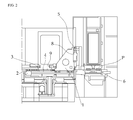
FIG. 1 is a perspective view showing a pallet transferring apparatus in the related art. -
FIG. 2 is a detailed diagram showing a linear shaft supporting structure of the pallet transferring apparatus in the related art. -
FIG. 3 is a perspective view of a pallet transferring apparatus according to the present invention. -
FIGS. 4 and5 are detailed diagrams showing a linear shaft supporting structure of the pallet transferring apparatus according to the present invention. -
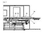
FIGS. 6 and7 are side views showing the linear shaft supporting structure of the pallet transferring apparatus according to the present invention. -
- P:
- Pallet
- 1:
- Carrier
- 2:
- Servo motor
- 3:
- Ball screw
- 4, 5:
- LM guide
- 6:
- Full stud
- 8:
- Hydraulic cylinder
- 9:
- Roll cover
- 10:
- Carrier
- 20:
- Servo motor
- 30:
- Decelerator
- 40:
- Pinion
- 50:
- Rack
- 60:
- Cam follower
- 61:
- First cam follower
- 62:
- Second cam follower
- 70:
- Pivot means
- 80:
- Rotating means (Hydraulic cylinder)
- 90:
- Slide cover
- Hereinafter, an exemplary embodiment of the present invention will be described in detail with reference to the accompanying drawings.
-
FIG. 3 is a perspective view of a pallet transferring apparatus according to the present invention,FIGS. 4 and5 are detailed perspective views of the pallet transferring apparatus according to the present invention, andFIGS. 6 and7 are side views of the pallet transferring apparatus according to the present invention. - As shown in the figures, a pallet (P) transferring apparatus of a horizontal type machine tool according to the present invention includes a
carrier 10, aservo motor 20, adecelerator 30, apinion 40, arack 50, and acam follower 60, and thepinion 40, therack 50, and thecam follower 60 replace roles of a ball screw and an LM guide in the related art. - The
carrier 10 as a means transferring a pallet P with the pallet P mounted thereon includes cam guide surfaces (not shown) on both sides, which engage with thecam follower 60 to be described below during forward and backward reciprocation transferring to guide forward and backward reciprocation transferring. - The
servo motor 20 generates driving force for forward and backward transferring movement of thecarrier 10. - The
decelerator 30 is connected to theservo motor 20 in series to serve to decelerate rotational force received from theservo motor 20 and increase torque. - When the
pinion 40 is installed on the side of thecarrier 10 and receives rotational force from a predetermined power source, thepinion 40 converts the received rotational force into linear movement to enable thecarrier 10 to reciprocate linearly. - The
rack 50 is connected to thedecelerator 30 to transfer the rotational force received from thedecelerator 30 to thepinion 40. That is, therack 50 transfers rotational movement received through theservo motor 20 and thedecelerator 30 to thepinion 40 and thepinion 40 converts the received rotational movement into linear reciprocating movement and thecarrier 10 coupled to thepinion 40 performs linear reciprocation transferring movement together with thepinion 40. - The
cam follower 60 as a means for guiding forward and backward reciprocating transferring of thecarrier 10 is fixed and disposed in plural at a predetermined interval along a forward/backward reciprocation transferring path of thecarrier 10 outside both sides of thecarrier 10. - Meanwhile, the center of each
cam follower 60 may be concentric, but is preferably eccentric to effectively fix both the top and the bottom of thecarrier 10. That is, thecam follower 60 which is eccentric slightly upward based on a center line of a reciprocation transferring path of thecarrier 10 in order to fix the top of thecarrier 10 and thecam follower 60 which is eccentric slightly downward based on a center line of the reciprocation transferring path of thecarrier 10 in order to fix the bottom of thecarrier 10 are alternately disposed, such that thecam followers 60 may be disposed in a sort of zigzag pattern. - Further, as shown in
FIG. 4B , according to a more preferable exemplary embodiment, thecam follower 60 may be constituted by afirst cam follower 61 and asecond cam follower 62. - The
first cam follower 61 is eccentric to fix both the top and the bottom of thecarrier 10 and thesecond cam follower 62 prevents horizontal swing of thecarrier 10. - Meanwhile, as shown in
FIG. 6 , the pallet (P) transferring apparatus of the horizontal type machine tool according to the present invention further includes a pivot means 70 and a rotating means (hydraulic cylinder) 80 and is configured by one fixation shaft and one rotational shaft that rotates around the pivot means 70 to receive the pallet P more simply, unlike a configuration of receiving the pallet P on two vertical and horizontal fixation shafts in the related art. - As shown in
FIG. 6 , the pivot means 70 is installed in the rear of a body of thecarrier 10. - In addition, the rotating means (hydraulic cylinder) 80 is provided in the front of the
carrier 10, such that as the rotating means (hydraulic cylinder) 80 extends, thecarrier 10 may rotate around the pivot means 70. - That is, the pivot means 70 is constituted by a fixation shaft (not shown) which is a part parallel to a horizontal plane regardless of displacement of the rotating means (hydraulic cylinder) 80 in the rear part of the pivot means 70 and a rotating shaft (not shown) which is a part of which an angle formed with the fixation shaft varies by rotating around the pivot means 70 according to the displacement of the rotating means (hydraulic cylinder) 80 in the front part of the pivot means 70.
- As such, the pivot means 70 is adopted, such that reception of the
carrier 10 and the pallet P is configured in one rotating shaft (not shown) structure which rotates around one fixation shaft (not shown) and the pivot means 70. Therefore, the configuration is remarkably simplified as compared with the configuration of receiving thecarrier 10 and the pallet P mounted thereon two horizontal and vertical fixation shafts in the related art. - Meanwhile, according to a more preferable exemplary embodiment, a
slide cover 90 may be adopted in order to prevent impurities of thecarrier 10 as shown inFIGS. 3 and 9. As shown in the figure, theslide cover 90 is configured in multistage, preferably in three stages, to be preferably configured in such a manner that an entire length of theslide cover 90 can extend and entire lengths of individual slide covers 91, 92, and 93 extend depending on forward and backward reciprocation transferring of thecarrier 10. - The
multistage slide cover 90 is remarkably better in durability and impurity infiltration prevention performance than a roll cover in the related art and effectively applicable to forward and backward reciprocation transfer of thecarrier 10. - An operational principle of the pallet (P) transferring apparatus of the horizontal type machine tool according to the present invention will be described based on the above configuration.
- First, forward and backward reciprocation transferring processes of the
carrier 10 and the pallet P mounted thereon will be described. - The rotational force of the
servo motor 20 is decelerated through thedecelerator 30 to be converted into an appropriate rotational speed and torque. Meanwhile, therack 50 connected to thedecelerator 30 in series rotates by receiving the rotational force from thedecelerator 30. - When the
rack 50 rotates, while thepinion 40 fixed onto both sides of thecarrier 10 engages with therack 30, the rotational movement received from therack 50 is converted into the linear reciprocation movement. - When the
pinion 40 is reciprocatively transferred, thecarrier 10 is also linearly and reciprocatively transferred together. Forward movement or backward movement of thecarrier 10 is determined according to a rotational direction of theservo motor 10. - Meanwhile, when the
carrier 10 is transferred forward and backward, thecarrier 10 engages with the cam guide surface (not shown) formed on both sides of thecarrier 10 and thecam follower 60 installed outside both sides of thecarrier 10, such that the forward and backward transferring of thecarrier 10 is guided by the plurality ofcam followers 60. In this case, eachcam follower 60 is disposed to be eccentric in the zigzag pattern to allow thecam follower 60 to be closely attached to the top and the bottom of thecarrier 10 simultaneously, thereby improving forward and backward transferring stability of thecarrier 10. - Meanwhile, the
multistage slide cover 90 is installed in an upper part of thecarrier 10, such that the length of themultistage slide cover 90 extends according to the forward and backward reciprocation transferring of thecarrier 10. - Next, receiving processes of the
carrier 10 and the pallet P mounted thereon will be described. - In order to receive the pallet P, the
carrier 10 is transferred forward and backward by thepinion 40, therack 50, and thecam follower 60 to place the pallet P at an appropriate position in a horizontal direction. - In this state, when the rotating means (hydraulic cylinder) 80 extends to push up the
carrier 10 and the pallet P mounted thereon, thecarrier 10 and the pallet P mounted thereon are transferred to a receivable position while rotating upward around the pivot means 70. - As such, according to the present invention, the pivot means 70 is adopted to receive the pallet P in a structure of one fixation shaft and one rotational shaft, and as a result, the structure is remarkably simplified as compared with the configuration of receiving the pallet P along two horizontal and vertical fixation shafts in the related art.
- As described above, although certain exemplary embodiments of the present invention has bee described in detail, it is to be understood by those skilled in the art that the spirit and scope of the present invention are not limited to the certain exemplary embodiments, but are intended to cover various modifications and changes without departing from the gist.
- Accordingly, since the above-mentioned exemplary embodiments are provided to inform those skilled in the art of the scope of the present invention, it should be understood that they are exemplary in all aspects and not limited and the present invention is just defined by the scope of the appended claims.
Claims (4)
- A pallet (P) transferring apparatus of a horizontal type machine tool, comprising:a carrier 10 transferring a pallet P and having cam guide surfaces on both sides;a servo motor 20;a decelerator 30 decelerating rotational force received from the servo motor 20 and increasing torque;a pinion 40 converting the rotational force into linear reciprocation movement of the carrier 10 when the pinion 40 is installed on the side of the carrier 10 and receives the rotational force;a rack 50 engaging with the pinion 40 and transferring the rotational force received from the decelerator 30 to the pinion 40; anda cam follower 60 engaging with the cam guide surface of the carrier 10 to guide forward and backward reciprocating transferring of the carrier 10.
- The pallet (P) transferring apparatus of a horizontal type machine tool of claim 1, further comprising:a pivot means 70 rotatably fixing a rotational shaft with respect to a fixation shaft parallel to a horizontal plane; anda rotating means 80 varying an angle between the carrier 10 on the rotational shaft and the horizontal plane by rotating the rotational shaft around the center of the pivot means 70.
- The pallet (P) transferring apparatus of a horizontal type machine tool of claim 1, further comprising:a slide cover 90 for protecting the carrier 10 from impurities according to a linear reciprocation transferring position of the carrier 10.
- The pallet (P) transferring apparatus of a horizontal type machine tool of claim 1, wherein the cam follower 60 includes:a first cam follower 61 which is eccentric to fix the top and the bottom of the carrier 10 simultaneously; anda second cam follower 62 for preventing horizontal swing of the carrier 10.
Applications Claiming Priority (2)
| Application Number | Priority Date | Filing Date | Title |
|---|---|---|---|
| KR1020090089315A KR20110032020A (en) | 2009-09-22 | 2009-09-22 | Pallet transfer unit in horizontal machining center |
| PCT/KR2010/006494 WO2011037402A2 (en) | 2009-09-22 | 2010-09-20 | Pallet conveying device of horizontal machining center |
Publications (3)
| Publication Number | Publication Date |
|---|---|
| EP2481520A2 true EP2481520A2 (en) | 2012-08-01 |
| EP2481520A4 EP2481520A4 (en) | 2013-07-24 |
| EP2481520B1 EP2481520B1 (en) | 2014-11-26 |
Family
ID=43796381
Family Applications (1)
| Application Number | Title | Priority Date | Filing Date |
|---|---|---|---|
| EP10819043.0A Not-in-force EP2481520B1 (en) | 2009-09-22 | 2010-09-20 | Pallet conveying device of horizontal machining center |
Country Status (5)
| Country | Link |
|---|---|
| US (1) | US20120255833A1 (en) |
| EP (1) | EP2481520B1 (en) |
| KR (1) | KR20110032020A (en) |
| CN (1) | CN102497955B (en) |
| WO (1) | WO2011037402A2 (en) |
Families Citing this family (17)
| Publication number | Priority date | Publication date | Assignee | Title |
|---|---|---|---|---|
| JP5497972B1 (en) * | 2012-08-10 | 2014-05-21 | ヤマザキマザック株式会社 | Vertical machining center |
| CN105451935B (en) * | 2014-05-22 | 2017-02-08 | 山崎马扎克公司 | Machine tool |
| JP6515354B2 (en) * | 2015-01-30 | 2019-05-22 | パナソニックIpマネジメント株式会社 | Robot transfer device |
| JP6460826B2 (en) * | 2015-02-16 | 2019-01-30 | 日特エンジニアリング株式会社 | Pallet transport device |
| CN105059858B (en) * | 2015-09-02 | 2017-04-12 | 深圳市宝尔威精密机械有限公司 | Automatic assembly line turning machine capable of achieving flexible turning and backwash |
| JP6615067B2 (en) * | 2015-09-08 | 2019-12-04 | Nittoku株式会社 | Pallet transport device |
| CN105108587A (en) * | 2015-10-10 | 2015-12-02 | 重庆大成优美数控科技有限公司 | Horizontal type numerical control machine tool |
| CN106516619A (en) * | 2016-12-22 | 2017-03-22 | 太仓美克斯机械设备有限公司 | Mutually-feeding device of material machines for production line |
| CN110065776A (en) * | 2018-01-24 | 2019-07-30 | 玉溪建福集团机床有限责任公司 | A kind of automatic conveying system of delivery type |
| CN108326572B (en) * | 2018-02-28 | 2023-12-12 | 科德数控股份有限公司 | Bridge type gantry numerical control machine tool workbench exchange system |
| US10919705B2 (en) * | 2018-05-29 | 2021-02-16 | The Procter And Gamble Company | Apparatus that controls motion of independent movers along a path |
| JP6741802B2 (en) * | 2019-01-25 | 2020-08-19 | Dmg森精機株式会社 | Pallet transfer system, pallet transfer method, and pallet transfer program |
| KR102013110B1 (en) | 2019-07-03 | 2019-08-21 | 진용삼 | Pallet circulation system for workpiece transfer |
| JP7236359B2 (en) * | 2019-09-13 | 2023-03-09 | オークマ株式会社 | Automatic pallet changer for machine tools |
| CN111451828B (en) * | 2020-04-11 | 2021-04-30 | 深圳市洪正科技有限公司 | Transmission equipment for machining of numerical control machine tool |
| CN112061737B (en) * | 2020-08-07 | 2022-07-05 | 兰州瑞奇戈德测控技术有限公司 | Workpiece horizontal rotating mechanism based on tray conveying |
| CN112518403B (en) * | 2020-11-26 | 2022-09-16 | 上海航天设备制造总厂有限公司 | Clamping device and clamping method for large component |
Family Cites Families (13)
| Publication number | Priority date | Publication date | Assignee | Title |
|---|---|---|---|---|
| US3934701A (en) * | 1975-03-28 | 1976-01-27 | Mooney Engineering, Inc. | Linear indexing machine |
| US4373840A (en) * | 1980-03-28 | 1983-02-15 | Giddings & Lewis, Inc. | Pallet transfer system |
| JPH0616977B2 (en) * | 1985-12-06 | 1994-03-09 | 豊田工機株式会社 | Pallet loading / unloading device |
| JPS63278738A (en) * | 1987-05-07 | 1988-11-16 | Kitamura Mach Co Ltd | Pallet exchange device |
| JPS63318236A (en) * | 1987-06-19 | 1988-12-27 | Kitamura Mach Co Ltd | Device for replacing pallet |
| JPH0647219B2 (en) * | 1988-10-17 | 1994-06-22 | キタムラ機械株式会社 | Pallet changer |
| CN1051878A (en) * | 1989-07-17 | 1991-06-05 | 马霍股份公司 | Lathe workpiece platen conversioning device |
| SE9101060D0 (en) * | 1991-04-09 | 1991-04-09 | Skf Specialty Product Ab | LINJAERENHET |
| JP2604055Y2 (en) * | 1993-06-16 | 2000-04-10 | 株式会社森精機製作所 | Machine tool pallet changer |
| JP4507309B2 (en) * | 1999-09-30 | 2010-07-21 | ブラザー工業株式会社 | Pallet change device |
| US6651799B1 (en) * | 2000-06-30 | 2003-11-25 | Wright Industries Incorporated | Modular pallet indexing chassis for automated manufacturing and assembly operations |
| KR100473556B1 (en) * | 2002-12-06 | 2005-03-09 | 대우종합기계 주식회사 | Automatic Pallet Changing Device Of Machining Center |
| DE602005005615T2 (en) * | 2004-12-29 | 2009-04-30 | Doosan Infracore Co., Ltd. | Pallet changer for a machine tool |
-
2009
- 2009-09-22 KR KR1020090089315A patent/KR20110032020A/en not_active Withdrawn
-
2010
- 2010-09-20 WO PCT/KR2010/006494 patent/WO2011037402A2/en not_active Ceased
- 2010-09-20 CN CN201080041795.0A patent/CN102497955B/en not_active Expired - Fee Related
- 2010-09-20 US US13/497,469 patent/US20120255833A1/en not_active Abandoned
- 2010-09-20 EP EP10819043.0A patent/EP2481520B1/en not_active Not-in-force
Also Published As
| Publication number | Publication date |
|---|---|
| EP2481520A4 (en) | 2013-07-24 |
| CN102497955B (en) | 2015-02-25 |
| EP2481520B1 (en) | 2014-11-26 |
| WO2011037402A2 (en) | 2011-03-31 |
| KR20110032020A (en) | 2011-03-30 |
| WO2011037402A3 (en) | 2011-09-01 |
| US20120255833A1 (en) | 2012-10-11 |
| CN102497955A (en) | 2012-06-13 |
Similar Documents
| Publication | Publication Date | Title |
|---|---|---|
| EP2481520B1 (en) | Pallet conveying device of horizontal machining center | |
| CN109625735B (en) | Conveying device for full-automatic safe deposit box object-viewing table | |
| US8640614B2 (en) | Work transfer apparatus for press machine, and work transfer unit | |
| CN107350872A (en) | Multiple-station rotation lifting combination feeding storage arrangement | |
| CN202625183U (en) | Automatic tray-conveying device | |
| CN214691970U (en) | Material supplying and receiving device | |
| CN112682362A (en) | Automatic assembling machine for cooling fan | |
| KR20170089723A (en) | Gentry transfer apparatus | |
| CN216470952U (en) | Charging tray conveying device | |
| CN222957905U (en) | Lens feeding mechanism and lens assembly device | |
| CN211619304U (en) | Material taking mechanism | |
| CN117228216B (en) | Conveying equipment for machining heat shield of automobile engine | |
| CN216271882U (en) | Long-life ultraprecise angular contact bearing abrasionproof decreases transfer device | |
| CN220825511U (en) | Elastomer surface processing equipment | |
| EP1747845A1 (en) | Machining centre with chuck structure displacable in a horizontal and a vertical direction | |
| CN216989936U (en) | Sheet processing device | |
| CN217127567U (en) | Integrated circuit lead frame electroplating and feeding integrated machine | |
| CN218560327U (en) | Feeding device | |
| CN112623721B (en) | Intelligent automatic moving and positioning blanking steel ball inserting machine | |
| CN211959008U (en) | Rotor assembly equipment | |
| CN109560032B (en) | Material taking device, feeding and discharging mechanism and feeding system | |
| US7032428B2 (en) | Feeding unit for transfer press | |
| CN113857829A (en) | Automatic assembling method and equipment for micro motor and industrial control equipment | |
| RU2296039C2 (en) | Automatic operator of the metal-cutting machines | |
| CN217544558U (en) | Intelligent taking, placing and transferring mechanism for silicon wafer sorting machine material box |
Legal Events
| Date | Code | Title | Description |
|---|---|---|---|
| PUAI | Public reference made under article 153(3) epc to a published international application that has entered the european phase |
Free format text: ORIGINAL CODE: 0009012 |
|
| 17P | Request for examination filed |
Effective date: 20120417 |
|
| AK | Designated contracting states |
Kind code of ref document: A2 Designated state(s): AL AT BE BG CH CY CZ DE DK EE ES FI FR GB GR HR HU IE IS IT LI LT LU LV MC MK MT NL NO PL PT RO SE SI SK SM TR |
|
| R17D | Deferred search report published (corrected) |
Effective date: 20110901 |
|
| DAX | Request for extension of the european patent (deleted) | ||
| A4 | Supplementary search report drawn up and despatched |
Effective date: 20130626 |
|
| RIC1 | Information provided on ipc code assigned before grant |
Ipc: B23Q 7/14 20060101ALI20130620BHEP Ipc: B23Q 7/08 20060101ALI20130620BHEP Ipc: B23Q 7/02 20060101ALI20130620BHEP Ipc: B23Q 7/00 20060101AFI20130620BHEP |
|
| 17Q | First examination report despatched |
Effective date: 20140210 |
|
| REG | Reference to a national code |
Ref country code: DE Ref legal event code: R079 Ref document number: 602010020601 Country of ref document: DE Free format text: PREVIOUS MAIN CLASS: B23Q0007000000 Ipc: B23Q0001260000 |
|
| GRAP | Despatch of communication of intention to grant a patent |
Free format text: ORIGINAL CODE: EPIDOSNIGR1 |
|
| RIC1 | Information provided on ipc code assigned before grant |
Ipc: B23Q 1/26 20060101AFI20140616BHEP |
|
| INTG | Intention to grant announced |
Effective date: 20140704 |
|
| GRAS | Grant fee paid |
Free format text: ORIGINAL CODE: EPIDOSNIGR3 |
|
| GRAA | (expected) grant |
Free format text: ORIGINAL CODE: 0009210 |
|
| AK | Designated contracting states |
Kind code of ref document: B1 Designated state(s): AL AT BE BG CH CY CZ DE DK EE ES FI FR GB GR HR HU IE IS IT LI LT LU LV MC MK MT NL NO PL PT RO SE SI SK SM TR |
|
| REG | Reference to a national code |
Ref country code: GB Ref legal event code: FG4D |
|
| REG | Reference to a national code |
Ref country code: CH Ref legal event code: EP |
|
| REG | Reference to a national code |
Ref country code: AT Ref legal event code: REF Ref document number: 697892 Country of ref document: AT Kind code of ref document: T Effective date: 20141215 |
|
| REG | Reference to a national code |
Ref country code: IE Ref legal event code: FG4D |
|
| REG | Reference to a national code |
Ref country code: DE Ref legal event code: R096 Ref document number: 602010020601 Country of ref document: DE Effective date: 20150108 |
|
| REG | Reference to a national code |
Ref country code: NL Ref legal event code: VDEP Effective date: 20141126 |
|
| REG | Reference to a national code |
Ref country code: AT Ref legal event code: MK05 Ref document number: 697892 Country of ref document: AT Kind code of ref document: T Effective date: 20141126 |
|
| REG | Reference to a national code |
Ref country code: LT Ref legal event code: MG4D |
|
| PG25 | Lapsed in a contracting state [announced via postgrant information from national office to epo] |
Ref country code: FI Free format text: LAPSE BECAUSE OF FAILURE TO SUBMIT A TRANSLATION OF THE DESCRIPTION OR TO PAY THE FEE WITHIN THE PRESCRIBED TIME-LIMIT Effective date: 20141126 Ref country code: IS Free format text: LAPSE BECAUSE OF FAILURE TO SUBMIT A TRANSLATION OF THE DESCRIPTION OR TO PAY THE FEE WITHIN THE PRESCRIBED TIME-LIMIT Effective date: 20150326 Ref country code: ES Free format text: LAPSE BECAUSE OF FAILURE TO SUBMIT A TRANSLATION OF THE DESCRIPTION OR TO PAY THE FEE WITHIN THE PRESCRIBED TIME-LIMIT Effective date: 20141126 Ref country code: NO Free format text: LAPSE BECAUSE OF FAILURE TO SUBMIT A TRANSLATION OF THE DESCRIPTION OR TO PAY THE FEE WITHIN THE PRESCRIBED TIME-LIMIT Effective date: 20150226 Ref country code: PT Free format text: LAPSE BECAUSE OF FAILURE TO SUBMIT A TRANSLATION OF THE DESCRIPTION OR TO PAY THE FEE WITHIN THE PRESCRIBED TIME-LIMIT Effective date: 20150326 Ref country code: NL Free format text: LAPSE BECAUSE OF FAILURE TO SUBMIT A TRANSLATION OF THE DESCRIPTION OR TO PAY THE FEE WITHIN THE PRESCRIBED TIME-LIMIT Effective date: 20141126 Ref country code: LT Free format text: LAPSE BECAUSE OF FAILURE TO SUBMIT A TRANSLATION OF THE DESCRIPTION OR TO PAY THE FEE WITHIN THE PRESCRIBED TIME-LIMIT Effective date: 20141126 |
|
| PG25 | Lapsed in a contracting state [announced via postgrant information from national office to epo] |
Ref country code: GR Free format text: LAPSE BECAUSE OF FAILURE TO SUBMIT A TRANSLATION OF THE DESCRIPTION OR TO PAY THE FEE WITHIN THE PRESCRIBED TIME-LIMIT Effective date: 20150227 Ref country code: CY Free format text: LAPSE BECAUSE OF FAILURE TO SUBMIT A TRANSLATION OF THE DESCRIPTION OR TO PAY THE FEE WITHIN THE PRESCRIBED TIME-LIMIT Effective date: 20141126 Ref country code: HR Free format text: LAPSE BECAUSE OF FAILURE TO SUBMIT A TRANSLATION OF THE DESCRIPTION OR TO PAY THE FEE WITHIN THE PRESCRIBED TIME-LIMIT Effective date: 20141126 Ref country code: SE Free format text: LAPSE BECAUSE OF FAILURE TO SUBMIT A TRANSLATION OF THE DESCRIPTION OR TO PAY THE FEE WITHIN THE PRESCRIBED TIME-LIMIT Effective date: 20141126 Ref country code: LV Free format text: LAPSE BECAUSE OF FAILURE TO SUBMIT A TRANSLATION OF THE DESCRIPTION OR TO PAY THE FEE WITHIN THE PRESCRIBED TIME-LIMIT Effective date: 20141126 Ref country code: AT Free format text: LAPSE BECAUSE OF FAILURE TO SUBMIT A TRANSLATION OF THE DESCRIPTION OR TO PAY THE FEE WITHIN THE PRESCRIBED TIME-LIMIT Effective date: 20141126 |
|
| PG25 | Lapsed in a contracting state [announced via postgrant information from national office to epo] |
Ref country code: EE Free format text: LAPSE BECAUSE OF FAILURE TO SUBMIT A TRANSLATION OF THE DESCRIPTION OR TO PAY THE FEE WITHIN THE PRESCRIBED TIME-LIMIT Effective date: 20141126 Ref country code: RO Free format text: LAPSE BECAUSE OF FAILURE TO SUBMIT A TRANSLATION OF THE DESCRIPTION OR TO PAY THE FEE WITHIN THE PRESCRIBED TIME-LIMIT Effective date: 20141126 Ref country code: SK Free format text: LAPSE BECAUSE OF FAILURE TO SUBMIT A TRANSLATION OF THE DESCRIPTION OR TO PAY THE FEE WITHIN THE PRESCRIBED TIME-LIMIT Effective date: 20141126 Ref country code: DK Free format text: LAPSE BECAUSE OF FAILURE TO SUBMIT A TRANSLATION OF THE DESCRIPTION OR TO PAY THE FEE WITHIN THE PRESCRIBED TIME-LIMIT Effective date: 20141126 Ref country code: CZ Free format text: LAPSE BECAUSE OF FAILURE TO SUBMIT A TRANSLATION OF THE DESCRIPTION OR TO PAY THE FEE WITHIN THE PRESCRIBED TIME-LIMIT Effective date: 20141126 |
|
| REG | Reference to a national code |
Ref country code: DE Ref legal event code: R097 Ref document number: 602010020601 Country of ref document: DE |
|
| PG25 | Lapsed in a contracting state [announced via postgrant information from national office to epo] |
Ref country code: PL Free format text: LAPSE BECAUSE OF FAILURE TO SUBMIT A TRANSLATION OF THE DESCRIPTION OR TO PAY THE FEE WITHIN THE PRESCRIBED TIME-LIMIT Effective date: 20141126 |
|
| PLBE | No opposition filed within time limit |
Free format text: ORIGINAL CODE: 0009261 |
|
| STAA | Information on the status of an ep patent application or granted ep patent |
Free format text: STATUS: NO OPPOSITION FILED WITHIN TIME LIMIT |
|
| 26N | No opposition filed |
Effective date: 20150827 |
|
| PG25 | Lapsed in a contracting state [announced via postgrant information from national office to epo] |
Ref country code: SI Free format text: LAPSE BECAUSE OF FAILURE TO SUBMIT A TRANSLATION OF THE DESCRIPTION OR TO PAY THE FEE WITHIN THE PRESCRIBED TIME-LIMIT Effective date: 20141126 |
|
| PG25 | Lapsed in a contracting state [announced via postgrant information from national office to epo] |
Ref country code: MC Free format text: LAPSE BECAUSE OF FAILURE TO SUBMIT A TRANSLATION OF THE DESCRIPTION OR TO PAY THE FEE WITHIN THE PRESCRIBED TIME-LIMIT Effective date: 20141126 Ref country code: LU Free format text: LAPSE BECAUSE OF FAILURE TO SUBMIT A TRANSLATION OF THE DESCRIPTION OR TO PAY THE FEE WITHIN THE PRESCRIBED TIME-LIMIT Effective date: 20150920 |
|
| REG | Reference to a national code |
Ref country code: CH Ref legal event code: PL |
|
| GBPC | Gb: european patent ceased through non-payment of renewal fee |
Effective date: 20150920 |
|
| REG | Reference to a national code |
Ref country code: IE Ref legal event code: MM4A |
|
| REG | Reference to a national code |
Ref country code: FR Ref legal event code: ST Effective date: 20160531 |
|
| PG25 | Lapsed in a contracting state [announced via postgrant information from national office to epo] |
Ref country code: GB Free format text: LAPSE BECAUSE OF NON-PAYMENT OF DUE FEES Effective date: 20150920 Ref country code: LI Free format text: LAPSE BECAUSE OF NON-PAYMENT OF DUE FEES Effective date: 20150930 Ref country code: IE Free format text: LAPSE BECAUSE OF NON-PAYMENT OF DUE FEES Effective date: 20150920 Ref country code: CH Free format text: LAPSE BECAUSE OF NON-PAYMENT OF DUE FEES Effective date: 20150930 |
|
| PG25 | Lapsed in a contracting state [announced via postgrant information from national office to epo] |
Ref country code: FR Free format text: LAPSE BECAUSE OF NON-PAYMENT OF DUE FEES Effective date: 20150930 |
|
| REG | Reference to a national code |
Ref country code: DE Ref legal event code: R082 Ref document number: 602010020601 Country of ref document: DE Representative=s name: VIERING, JENTSCHURA & PARTNER MBB PATENT- UND , DE Ref country code: DE Ref legal event code: R081 Ref document number: 602010020601 Country of ref document: DE Owner name: DOOSAN MACHINE TOOLS CO., LTD., CHANG-WON-SI, KR Free format text: FORMER OWNER: DOOSAN INFRACORE CO., LTD., DONG-GU, INCHEON, KR |
|
| PG25 | Lapsed in a contracting state [announced via postgrant information from national office to epo] |
Ref country code: MT Free format text: LAPSE BECAUSE OF FAILURE TO SUBMIT A TRANSLATION OF THE DESCRIPTION OR TO PAY THE FEE WITHIN THE PRESCRIBED TIME-LIMIT Effective date: 20141126 |
|
| PG25 | Lapsed in a contracting state [announced via postgrant information from national office to epo] |
Ref country code: SM Free format text: LAPSE BECAUSE OF FAILURE TO SUBMIT A TRANSLATION OF THE DESCRIPTION OR TO PAY THE FEE WITHIN THE PRESCRIBED TIME-LIMIT Effective date: 20141126 Ref country code: HU Free format text: LAPSE BECAUSE OF FAILURE TO SUBMIT A TRANSLATION OF THE DESCRIPTION OR TO PAY THE FEE WITHIN THE PRESCRIBED TIME-LIMIT; INVALID AB INITIO Effective date: 20100920 Ref country code: BG Free format text: LAPSE BECAUSE OF FAILURE TO SUBMIT A TRANSLATION OF THE DESCRIPTION OR TO PAY THE FEE WITHIN THE PRESCRIBED TIME-LIMIT Effective date: 20141126 |
|
| PG25 | Lapsed in a contracting state [announced via postgrant information from national office to epo] |
Ref country code: TR Free format text: LAPSE BECAUSE OF FAILURE TO SUBMIT A TRANSLATION OF THE DESCRIPTION OR TO PAY THE FEE WITHIN THE PRESCRIBED TIME-LIMIT Effective date: 20141126 |
|
| PG25 | Lapsed in a contracting state [announced via postgrant information from national office to epo] |
Ref country code: BE Free format text: LAPSE BECAUSE OF FAILURE TO SUBMIT A TRANSLATION OF THE DESCRIPTION OR TO PAY THE FEE WITHIN THE PRESCRIBED TIME-LIMIT Effective date: 20141126 |
|
| PG25 | Lapsed in a contracting state [announced via postgrant information from national office to epo] |
Ref country code: MK Free format text: LAPSE BECAUSE OF FAILURE TO SUBMIT A TRANSLATION OF THE DESCRIPTION OR TO PAY THE FEE WITHIN THE PRESCRIBED TIME-LIMIT Effective date: 20141126 |
|
| PG25 | Lapsed in a contracting state [announced via postgrant information from national office to epo] |
Ref country code: AL Free format text: LAPSE BECAUSE OF FAILURE TO SUBMIT A TRANSLATION OF THE DESCRIPTION OR TO PAY THE FEE WITHIN THE PRESCRIBED TIME-LIMIT Effective date: 20141126 |
|
| PGFP | Annual fee paid to national office [announced via postgrant information from national office to epo] |
Ref country code: DE Payment date: 20190910 Year of fee payment: 10 Ref country code: IT Payment date: 20190917 Year of fee payment: 10 |
|
| REG | Reference to a national code |
Ref country code: DE Ref legal event code: R119 Ref document number: 602010020601 Country of ref document: DE |
|
| PG25 | Lapsed in a contracting state [announced via postgrant information from national office to epo] |
Ref country code: DE Free format text: LAPSE BECAUSE OF NON-PAYMENT OF DUE FEES Effective date: 20210401 |
|
| PG25 | Lapsed in a contracting state [announced via postgrant information from national office to epo] |
Ref country code: IT Free format text: LAPSE BECAUSE OF NON-PAYMENT OF DUE FEES Effective date: 20200920 |