EP2479602A1 - Liquid crystal display device - Google Patents
Liquid crystal display device Download PDFInfo
- Publication number
- EP2479602A1 EP2479602A1 EP10817006A EP10817006A EP2479602A1 EP 2479602 A1 EP2479602 A1 EP 2479602A1 EP 10817006 A EP10817006 A EP 10817006A EP 10817006 A EP10817006 A EP 10817006A EP 2479602 A1 EP2479602 A1 EP 2479602A1
- Authority
- EP
- European Patent Office
- Prior art keywords
- liquid crystal
- crystal display
- see
- plate
- side wall
- Prior art date
- Legal status (The legal status is an assumption and is not a legal conclusion. Google has not performed a legal analysis and makes no representation as to the accuracy of the status listed.)
- Granted
Links
- 239000004973 liquid crystal related substance Substances 0.000 title claims abstract description 121
- 229920005989 resin Polymers 0.000 claims abstract description 25
- 239000011347 resin Substances 0.000 claims abstract description 25
- 229920003002 synthetic resin Polymers 0.000 claims abstract description 12
- 239000000057 synthetic resin Substances 0.000 claims abstract description 12
- 238000000465 moulding Methods 0.000 claims description 46
- 230000000007 visual effect Effects 0.000 claims description 7
- 239000011521 glass Substances 0.000 abstract description 32
- 230000010287 polarization Effects 0.000 abstract description 10
- 230000015572 biosynthetic process Effects 0.000 abstract description 5
- 239000000758 substrate Substances 0.000 description 18
- 239000000428 dust Substances 0.000 description 11
- 239000004925 Acrylic resin Substances 0.000 description 7
- 229920000178 Acrylic resin Polymers 0.000 description 7
- 230000002349 favourable effect Effects 0.000 description 6
- 239000000463 material Substances 0.000 description 6
- 229920005668 polycarbonate resin Polymers 0.000 description 3
- 239000004431 polycarbonate resin Substances 0.000 description 3
- 239000001058 brown pigment Substances 0.000 description 2
- 238000004040 coloring Methods 0.000 description 2
- 238000010276 construction Methods 0.000 description 2
- 230000005540 biological transmission Effects 0.000 description 1
- 238000005286 illumination Methods 0.000 description 1
- 230000004048 modification Effects 0.000 description 1
- 238000012986 modification Methods 0.000 description 1
- 230000002093 peripheral effect Effects 0.000 description 1
- 239000002861 polymer material Substances 0.000 description 1
- XLYOFNOQVPJJNP-UHFFFAOYSA-N water Substances O XLYOFNOQVPJJNP-UHFFFAOYSA-N 0.000 description 1
Images


Classifications
-
- G—PHYSICS
- G02—OPTICS
- G02F—OPTICAL DEVICES OR ARRANGEMENTS FOR THE CONTROL OF LIGHT BY MODIFICATION OF THE OPTICAL PROPERTIES OF THE MEDIA OF THE ELEMENTS INVOLVED THEREIN; NON-LINEAR OPTICS; FREQUENCY-CHANGING OF LIGHT; OPTICAL LOGIC ELEMENTS; OPTICAL ANALOGUE/DIGITAL CONVERTERS
- G02F1/00—Devices or arrangements for the control of the intensity, colour, phase, polarisation or direction of light arriving from an independent light source, e.g. switching, gating or modulating; Non-linear optics
- G02F1/01—Devices or arrangements for the control of the intensity, colour, phase, polarisation or direction of light arriving from an independent light source, e.g. switching, gating or modulating; Non-linear optics for the control of the intensity, phase, polarisation or colour
- G02F1/13—Devices or arrangements for the control of the intensity, colour, phase, polarisation or direction of light arriving from an independent light source, e.g. switching, gating or modulating; Non-linear optics for the control of the intensity, phase, polarisation or colour based on liquid crystals, e.g. single liquid crystal display cells
- G02F1/133—Constructional arrangements; Operation of liquid crystal cells; Circuit arrangements
- G02F1/1333—Constructional arrangements; Manufacturing methods
-
- B—PERFORMING OPERATIONS; TRANSPORTING
- B60—VEHICLES IN GENERAL
- B60K—ARRANGEMENT OR MOUNTING OF PROPULSION UNITS OR OF TRANSMISSIONS IN VEHICLES; ARRANGEMENT OR MOUNTING OF PLURAL DIVERSE PRIME-MOVERS IN VEHICLES; AUXILIARY DRIVES FOR VEHICLES; INSTRUMENTATION OR DASHBOARDS FOR VEHICLES; ARRANGEMENTS IN CONNECTION WITH COOLING, AIR INTAKE, GAS EXHAUST OR FUEL SUPPLY OF PROPULSION UNITS IN VEHICLES
- B60K35/00—Arrangement of adaptations of instruments
-
- B60K35/415—
-
- B60K35/60—
-
- G—PHYSICS
- G01—MEASURING; TESTING
- G01D—MEASURING NOT SPECIALLY ADAPTED FOR A SPECIFIC VARIABLE; ARRANGEMENTS FOR MEASURING TWO OR MORE VARIABLES NOT COVERED IN A SINGLE OTHER SUBCLASS; TARIFF METERING APPARATUS; MEASURING OR TESTING NOT OTHERWISE PROVIDED FOR
- G01D7/00—Indicating measured values
-
- G—PHYSICS
- G02—OPTICS
- G02F—OPTICAL DEVICES OR ARRANGEMENTS FOR THE CONTROL OF LIGHT BY MODIFICATION OF THE OPTICAL PROPERTIES OF THE MEDIA OF THE ELEMENTS INVOLVED THEREIN; NON-LINEAR OPTICS; FREQUENCY-CHANGING OF LIGHT; OPTICAL LOGIC ELEMENTS; OPTICAL ANALOGUE/DIGITAL CONVERTERS
- G02F1/00—Devices or arrangements for the control of the intensity, colour, phase, polarisation or direction of light arriving from an independent light source, e.g. switching, gating or modulating; Non-linear optics
- G02F1/01—Devices or arrangements for the control of the intensity, colour, phase, polarisation or direction of light arriving from an independent light source, e.g. switching, gating or modulating; Non-linear optics for the control of the intensity, phase, polarisation or colour
- G02F1/13—Devices or arrangements for the control of the intensity, colour, phase, polarisation or direction of light arriving from an independent light source, e.g. switching, gating or modulating; Non-linear optics for the control of the intensity, phase, polarisation or colour based on liquid crystals, e.g. single liquid crystal display cells
- G02F1/133—Constructional arrangements; Operation of liquid crystal cells; Circuit arrangements
- G02F1/1333—Constructional arrangements; Manufacturing methods
- G02F1/1335—Structural association of cells with optical devices, e.g. polarisers or reflectors
-
- G—PHYSICS
- G09—EDUCATION; CRYPTOGRAPHY; DISPLAY; ADVERTISING; SEALS
- G09F—DISPLAYING; ADVERTISING; SIGNS; LABELS OR NAME-PLATES; SEALS
- G09F9/00—Indicating arrangements for variable information in which the information is built-up on a support by selection or combination of individual elements
- G09F9/30—Indicating arrangements for variable information in which the information is built-up on a support by selection or combination of individual elements in which the desired character or characters are formed by combining individual elements
- G09F9/35—Indicating arrangements for variable information in which the information is built-up on a support by selection or combination of individual elements in which the desired character or characters are formed by combining individual elements being liquid crystals
-
- B60K2360/20—
-
- B60K2360/693—
-
- G—PHYSICS
- G02—OPTICS
- G02F—OPTICAL DEVICES OR ARRANGEMENTS FOR THE CONTROL OF LIGHT BY MODIFICATION OF THE OPTICAL PROPERTIES OF THE MEDIA OF THE ELEMENTS INVOLVED THEREIN; NON-LINEAR OPTICS; FREQUENCY-CHANGING OF LIGHT; OPTICAL LOGIC ELEMENTS; OPTICAL ANALOGUE/DIGITAL CONVERTERS
- G02F1/00—Devices or arrangements for the control of the intensity, colour, phase, polarisation or direction of light arriving from an independent light source, e.g. switching, gating or modulating; Non-linear optics
- G02F1/01—Devices or arrangements for the control of the intensity, colour, phase, polarisation or direction of light arriving from an independent light source, e.g. switching, gating or modulating; Non-linear optics for the control of the intensity, phase, polarisation or colour
- G02F1/13—Devices or arrangements for the control of the intensity, colour, phase, polarisation or direction of light arriving from an independent light source, e.g. switching, gating or modulating; Non-linear optics for the control of the intensity, phase, polarisation or colour based on liquid crystals, e.g. single liquid crystal display cells
- G02F1/1306—Details
Definitions
- the present invention relates to a liquid crystal display device mounted on a special vehicle such as a construction machine, ships, or cars, for example, and performs illumination and display in a liquid crystal display with light rays applied from a light source.
- a conventionally known liquid crystal display device for cars or the like includes a liquid crystal display having a liquid crystal sealed in between a pair of glass substrates and also having a polarizing plate provided on each of a front side and a rear side of the glass substrates, a circuit substrate having a driving circuit mounted thereon for driving the liquid crystal display, a light source mounted on the circuit substrate and illuminating the liquid crystal display for realizing display, a casing housing the liquid crystal display and the light source, and a see-through plate made of synthetic resin, covering an opening portion on the front of the casing, protecting the liquid crystal display, preventing entry of dust from the outside to the inside of the casing, and allowing excellent visibility of the liquid crystal display.
- Patent Document 1 and Patent Document 2 See, for example, Patent Document 1 and Patent Document 2
- Such a see-through plate made of synthetic resin typically has the advantages of high strength and easy molding in molding even when it has a complicated shape.
- a polycarbonate resin or an acrylic resin having a transmission property is used. This provides the advantage that the see-through plate covering the front side of the casing can be easily molded from the synthetic resin material even when it has a complicated shape.
- the use of the polycarbonate resin or the acrylic resin allows favorable visual recognition of practically required display contents on the liquid crystal display through the use of the see-through plate (the substrate made of the synthetic resin) of a polymer material serving as a polarization-property relieving plate which relieves the polarization property on the front side of the liquid crystal display 2.
- liquid crystal display devices described in Patent Document 1 and Patent Document 2 mentioned above since some areas of a protecting cover (see-through plate) placed on the front side of the liquid crystal display may have resin molecules oriented nonuniformly near a gate port in molding the resin of the see-through plate serving as the protecting cover, the areas may be seen through polarizing glasses in a visible range of a liquid crystal display portion. When the liquid crystal display is seen through the polarizing glasses, a black shadow may partially appear in the presence of the disorder of the orientation direction of the molecules in the visible range due to molding stress, which may prevent reading of display.
- anisotropy of refractive index occurs near the gate port due to the molding stress portion produced from the molding, and as a result, when the display is seen through the polarizing glasses, a partially black area coinciding with a direction orthogonal to the polarization axis of the polarizing glasses may be found.
- a liquid crystal display device capable of favorable visual recognition of display contents on a liquid crystal display by providing a gate port in molding of resin of a see-through plate serving as a protecting cover at a position located at a distance from an area where the liquid crystal display is visually recognized when the resin of the see-through plate is molded.
- a liquid crystal display device including a liquid crystal display including a liquid crystal sealed in between a pair of glass substrates and including a polarizing plate provided on each of a front side and a rear side of the glass substrate, a casing housing the liquid crystal display, and a see-through plate made of synthetic resin, covering an opening portion on a front of the casing, and provided for visual recognition of a display portion area of the liquid crystal display, characterized in that the see-through plate is provided with a side wall extending continuously from an area for visually recognizing the liquid crystal display so as to surround an outside of an end portion of the opening portion on the front of the casing, and the side wall is provided with a gate port in molding of a resin of the see-through plate at a position located at a distance from the area for visually recognizing the liquid crystal display.
- the gate port provided at the position of the side wall of the see-through plate at a distance from the visible range of the liquid crystal display portion causes anisotropy of refractive index due to molding stress produced in molding only near the gate port, and as a result, a portion partially appearing black occurs only in the portion of the side wall of the see-through plate that coincides with a direction orthogonal to the polarization axis of the polarizing glasses when the display is seen through the polarizing glasses.
- the liquid crystal display device is characterized in that the side wall is provided with a protruding portion at a position located at a distance from the area for visually recognizing the liquid crystal display, and the gate port in molding of the resin of the see-through plate is provided at a position of the protruding portion.
- the protruding portion is provided at the position located at a distance from the area for visually recognizing the liquid crystal display, and the gate port in molding of the resin of the see-through plate is provided at the position of the protruding portion, a portion partially appearing black occurs only in the position of the protruding portion protruding from the side wall of the see-through plate and the portion of the side wall that coincide with the direction orthogonal to the polarization axis of the polarizing glasses when the display is seen through the polarizing glasses.
- the liquid crystal display device according to claim 2 is characterized in that the protruding portion protruding from the side wall provided with the gate port is formed in a generally trapezoidal shape tapered with the gate port as a base point.
- the formation of the side wall of the see-through plate formed in the generally trapezoidal shape tapered with the gate port as the base point allows favorable resin fluidity in the molding of the synthetic resin material.
- the molding stress in the resin molding can be relieved to reduce the size of the area having anisotropy of refractive index due to the molding stress.
- a portion partially appearing black is only the narrow area of the side wall of the see-through plate coinciding with the direction orthogonal to the polarization axis of the polarizing glasses.
- the liquid crystal display device according to any one of claims 1 to 3 is characterized in that a dust-preventative rib is formed to protrude opposite to a position of an end portion of the side wall and integrally with the casing.
- the dust-preventative rib formed opposite to the position of the end portion of the side wall of the see-through plate and integrally with the casing can prevent entry of dust from the gap portion serving as the boundary between the side wall provided for the see-through plate and the casing.
- the liquid crystal display device according to any one of claims 1 to 4 is characterized in that the see-through plate is colored and molded.
- the color of the display portion of the liquid crystal display device transmitted through the see-through plate is entirely illuminated through the color of the see-through plate, and the liquid crystal display device is placed at a position behind the see-through plate, so that a sense of greater depth and a three-dimensional appearance can be enhanced.
- the liquid crystal display device according to any one of claims 1 to 5 is characterized in that the area for visually recognizing the liquid crystal display on the front side of the see-through plate is formed in an arc curved shape.
- the liquid crystal display device can be provided with no confusion and excellent visibility.
- the intended object can be achieved. Even when the display contents on the liquid crystal display device are seen through the polarizing glasses, the gate port provided at the position of the side wall of the see-through plate at a distance from the visible range of the liquid crystal display portion causes no anisotropy of refractive index due to molding at a position located at a distance from the gate port (no limitation in direction), so that light passes through the position and thus the display contents on the liquid crystal display can be favorably recognized visually when they are seen through the polarizing glasses.
- a liquid crystal display device is described in detail with an example of a liquid crystal display device used for a vehicle.
- embodiments of the present invention are described with reference to the drawings.
- a liquid crystal display device 1 of the present embodiment includes a liquid crystal display 2 having a liquid crystal sealed in between a pair of glass substrates 2a and 2b and also having polarizing plates 2c and 2d provided on a front side and a rear side of the glass substrate 2a and 2b, respectively, a circuit substrate 3 having a driving circuit 3a mounted thereon for driving the liquid crystal display 2, a light source 4 formed of a light-emitting diode or the like, mounted on the circuit substrate 3, and illuminating the liquid crystal display 2 for realizing display, a holder 5 holding the liquid crystal display 2 and the circuit substrate 3, a casing 6 housing the liquid crystal display 2, the circuit substrate 3, and the holder 5, and a see-through plate 7 made, for example of acrylic resin, covering an opening portion on the front of the casing 6, protecting the polarizing plate 2c placed on the front side of the liquid crystal display 2, preventing entry of dust from the outside to the inside of the casing 6, and provided with an area
- the casing 6 in the present embodiment is formed of a casing member 60 housing the liquid crystal display 2, the circuit substrate 3, and the holder 5, and a casing member 61 in hood form placed on a front side of the casing member 60 and provided with an opening portion 61a for visual recognition of the display portion area of the liquid crystal display 2.
- the see-through plate 7 made of acrylic resin described above is provided on a front side of the casing member 61 in hood form which constitutes part of the casing 6.
- the see-through plate 7 is provided with a side wall 7a extending continuously in a direction substantially orthogonal to the area for visually recognizing the liquid crystal display 2 so as to surround the outside of an end portion of an opening portion on the front of the casing 6 (the casing member 61 in hood form).
- the side wall 7a has a protruding portion 7b at a position located at a distance from the area for visually recognizing the liquid crystal display 2.
- a gate port 7c in resin molding of the see-through plat 7 is provided at the position of the protruding portion 7b.
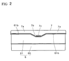
- the protruding portion 7b of the side wall 7a provided with the gate port 7c has a generally trapezoidal shape tapered with the gate port 7c as a base point, as shown in Fig. 1 and Fig. 2 .
- the area for visually recognizing the liquid crystal display 2 on the front side of the see-through plate 7 is formed in an arc curved shape R so that an observer is not confused when the observer visually recognizes the liquid crystal display 2 from the front side.
- the casing member 61 has a dust-preventative rib 61b integrally provided to protrude at a position opposite to the end face of the side wall 7a of the see-through plate 7 so as to prevent entry of dust from between the casing member 61 in hood form constituting part of the casing 6 and the see-through plate 7.
- liquid crystal display In the liquid crystal display according to the first embodiment configured in this manner, display contents (display information) on the liquid crystal display 2 are illuminated transmissively from behind by light from the light source 4. Since the front side of the see-through plate 7 located at a position at a distance from the gate port 7c of the see-through plate 7 has no anisotropy of refractive index due to molding (no limitation in direction), the light passes through the front side as it is, and the display contents on the liquid crystal display 2 can be visually recognized favorably even when it is seen through polarizing glasses.
- the gate port 7c is provided at the position of the protruding portion 7b at the position of the side wall 7a of the see-through 7 at a distance from the visible range of the liquid crystal display 2 and thus the refractive index is anisotropic only near the gate port 7c due to the molding stress produced in molding since, and as a result, the areas partially appearing black are only the protruding portion 7b and the side wall 7a of the see-through plate 7 coinciding with a direction orthogonal to the polarization axis of the polarizing glasses when viewed through the polarizing glasses.
- the other area or the front side of the see-through plate 7 which is the area for visually recognizing the liquid crystal display 2 at the position at a distance from the gate port 7c has no anisotropy of refractive index due to the molding as described above (no limitation in direction), so that the light passes as it is, and the display contents on the liquid crystal display 2 can be favorably read and understood even when they are seen through the polarizing glasses.
- the protruding portion 7b formed to protrude from the side wall 7a provided with the gate port 7c is formed in the generally trapezoidal shape tapered with the gate port 7c as the base point.
- the formation of the protruding portion 7b of the side wall 7a of the see-through plate 7 in the generally trapezoidal shape tapered with the gate port 7c as the base point allows favorable resin fluidity in the molding of the synthetic resin material. As a result, the molding stress in the resin molding can be relieved to reduce the size of the area having anisotropy of refractive index due to the molding stress.
- the generally trapezoidal shape tapered around the gate port 7c can reduce the size of the area under the molding stress in the resin molding.
- the portion partially appearing black is only the narrow area (the area under the molding stress in the molding) of the side wall 7a of the see-through plate 7 coinciding with the direction orthogonal to the polarization axis of the polarizing glasses, so that the depth dimension of the side wall 7a can be reduced.
- the area for visually recognizing the liquid crystal display 2 on the front side of the see-through plate 7 is formed in the arc curved shape R to prevent confusion when the observer visually recognizes the liquid crystal display 2 from the front side. Even when external light is incident on the front side of the liquid crystal display 2 from the outside, the light rays are reflected on the see-through plate 7 and then reflected in a horizontal direction (other than a line-of-vision direction) without returning to the line-of-vision direction because of the curved shape R of the arc shape, the display contents on the liquid crystal display 2 can be favorably recognized without confusion.
- the casing 6 has the dust-preventative rib 61b integrally provided to protrude at the position opposite to the end face of the side wall 7a of the see-through plate 7. Even when dust is to enter from the end side of the side wall 7a of the see-through 7, the dust-preventative rib 61b formed to protrude from the casing 6 can block the dust.
- the dust-preventative rib 61b provided opposite to the end face of the side wall 7a of the see-through plate 7 integrally with the casing member 61 in hood form can prevent dust from entering from the gap portion serving as the boundary between the side wall 7a provided for the see-through plate 7 and the casing member 61.
- Fig. 4 to Fig. 7 shows a second embodiment of the present invention.
- Components identical to or equivalent to the components described in the first embodiment are designated and described with the same reference numerals.
- a liquid crystal display device 1 has a liquid crystal display 2, a circuit substrate 3 having a light source 4 mounted thereon, and a holder 5 which are housed in a casing 6, and also has a see-through plate 70 made, for example of acrylic resin, covering an opening portion on the front of the casing 6, protecting a polarizing plate 2c placed on a front side of the liquid crystal display 2, preventing entry of dust from the outside to the inside of the casing 6, provided with an area for visually recognizing a display portion area of the liquid crystal display 2.
- the casing 6 in the present embodiment is formed of a casing member 600 housing the liquid crystal display 2, the circuit substrate 3, and the holder 5, and a casing member 610 in frame form placed on a front side of the liquid crystal display 2 housed in the casing member 600, closing the gap portion between the outside of the display area of the liquid crystal display 2 and an inner wall portion of the casing member 600, provided with an opening portion 610a for visual recognition of the display portion area of the liquid crystal display 2.
- the see-through plate 70 made of acrylic resin described above is provided on a front side of the casing member 600 which constitutes part of the casing 6.
- the casing member 600 has a dust-preventative rib 600a integrally provided to protrude at a position opposite to the end face of the side wall 70a of the see-through plate 70 so as to prevent entry of dust from between the casing member 600 and the see-through plate 700.
- a protruding portion 70b formed to protrude from the side wall 70a provided with the gate port 70c has a generally trapezoidal shape tapered with the gate port 70c as a base point.
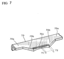
- the thickness dimensions of the gate port 70c are formed such that the central portion is formed as a thin portion T1 and both end portions of the generally trapezoidal and tapered shape are formed as a thick portion T2. (See Fig. 7 )
- the see-through plate 70 is molded with coloring in a predetermined color by mixing black or brown pigments.
- liquid crystal display configured in this manner, substantially similarly to the first embodiment, display contents (display information) on the liquid crystal display 2 are illuminated transmissively from behind by light from the light source 4. Since the front side of the see-through plate 70 located at a position at a distance from the gate port 70c of the see-through plate 7 has no anisotropy of refractive index due to molding (no limitation in direction), the light passes through the front side as it is, and the display contents on the liquid crystal display 2 can be visually recognized favorably even when it is seen through polarizing glasses.
- the protruding portion 70b formed to protrude from the side wall 70a provided with the gate port 70c is formed in the generally trapezoidal shape tapered with the gate port 70c as the base point, and the thickness dimensions of the gate port 70c are formed such that the central portion is formed as the thin portion T1 and both end portions of the generally trapezoidal and tapered shape are formed as the thick portion T2, the generally trapezoidal shape tapered with the gate port 70c as the base point allows favorable resin fluidity in the molding of the synthetic resin material substantially similarly to the first embodiment described above. As a result, the molding stress in the resin molding can be relieved to reduce the size of the area having anisotropy of refractive index due to the molding stress.
- the thickness dimensions of the gate port 70c are formed such that the central portion is formed as the thin portion T1 and both end portions are formed as the thick portion T2, the flow of the resin in the molding is enhanced on both sides as compared with the central portion to allow uniform flow over the entire see-through plate 7 in the resin molding.
- the resin fluidity in the molding of the synthetic resin material can be enhanced and the flow in the resin molding can be uniformalized.
- the molding stress can be relieved to reduce the size of the area where the orientation direction of the resin molecules is nonuniform. This can widen the area with the proper orientation direction of the molecules in the resin molding relative to the polarization axis direction of the polarizing plate of the liquid crystal display.
- the see-through plate 70 itself is molded with coloring in a predetermined color by mixing black or brown pigments, the color of the display portion of the liquid crystal display 2 transmitted through the see-through plate 70 is entirely illuminated through the color of the see-through plate 70, and the liquid crystal display 2 appears to be placed at a position behind the see-through plate 70, so that a sense of greater depth and a three-dimensional appearance can be enhanced.
- the casing member 610 in frame form covering the outer peripheral portion of the liquid crystal display 2 is visually recognized through the colored see-through plate 70, only the liquid crystal display 2 appears to be isolated against a dark background.
- the liquid crystal display 1 with favorable appearance can be provided.
- the casing 600 has the dust-preventative rib 600a integrally provided to protrude at the position opposite to the end face of the side wall 70a of the see-through plate 70. Even when dust is to enter from the end portion of the side wall 70a of the see-through 70, the dust-preventative rib 600a formed to protrude from the casing 600 can block the dust.
- the present invention is not limited to the embodiments described above, and various modification can be made without departing from the spirit or scope of the present invention.
- the protruding portions 7b and 70b formed to protrude from the side walls 7a and 70a located on the upper side of the see-through plates 7 and 70 are formed in the generally trapezoidal shapes in the embodiments described above. They are not limited to the generally trapezoidal shape but an arc protruding portion may be used.
- the placement positions of the gate ports 7c and 70c are not limited to the end portions, and may be set to the central position in some cases.
- the depth and the width dimensions of the protruding portions 7b and 70b may be set depending on the depth dimensions of the side walls 7a and 70a provided for the see-through plates 7 and 70.
- the position for placing the gate ports 7c and 70c may be set as appropriate in accordance with the positions of the protruding portions 7b and 70b.
- the acrylic resin is used as the synthetic resin material of the see-through plates 7 and 70 in the embodiments, another transmissive resin such as a polycarbonate resin can be used for the formation.
- the liquid crystal display device has been described with the example of an indicator for a vehicle such as a car.
- the present invention is not limited to the indicator for vehicle but is applicable to an indicator for a ship, or an indicator for a special vehicle such as an agricultural machine and a construction machine, or a liquid crystal display provided for a remote-control operation panel of a water heater or the like, or a commercial device such as a videocassette recorder and an audio product.
Abstract
Description
- The present invention relates to a liquid crystal display device mounted on a special vehicle such as a construction machine, ships, or cars, for example, and performs illumination and display in a liquid crystal display with light rays applied from a light source.
- A conventionally known liquid crystal display device for cars or the like includes a liquid crystal display having a liquid crystal sealed in between a pair of glass substrates and also having a polarizing plate provided on each of a front side and a rear side of the glass substrates, a circuit substrate having a driving circuit mounted thereon for driving the liquid crystal display, a light source mounted on the circuit substrate and illuminating the liquid crystal display for realizing display, a casing housing the liquid crystal display and the light source, and a see-through plate made of synthetic resin, covering an opening portion on the front of the casing, protecting the liquid crystal display, preventing entry of dust from the outside to the inside of the casing, and allowing excellent visibility of the liquid crystal display. (See, for example,
Patent Document 1 and Patent Document 2) - Such a see-through plate made of synthetic resin typically has the advantages of high strength and easy molding in molding even when it has a complicated shape. For example, a polycarbonate resin or an acrylic resin having a transmission property is used. This provides the advantage that the see-through plate covering the front side of the casing can be easily molded from the synthetic resin material even when it has a complicated shape. It is also known that, even when an observer wears polarizing glasses, the use of the polycarbonate resin or the acrylic resin allows favorable visual recognition of practically required display contents on the liquid crystal display through the use of the see-through plate (the substrate made of the synthetic resin) of a polymer material serving as a polarization-property relieving plate which relieves the polarization property on the front side of the
liquid crystal display 2. -
- Patent Document 1:
JP-A-4-65319 - Patent Document 2:
JP-A-10-214036 - In liquid crystal display devices described in
Patent Document 1 andPatent Document 2 mentioned above, since some areas of a protecting cover (see-through plate) placed on the front side of the liquid crystal display may have resin molecules oriented nonuniformly near a gate port in molding the resin of the see-through plate serving as the protecting cover, the areas may be seen through polarizing glasses in a visible range of a liquid crystal display portion. When the liquid crystal display is seen through the polarizing glasses, a black shadow may partially appear in the presence of the disorder of the orientation direction of the molecules in the visible range due to molding stress, which may prevent reading of display. In other words, anisotropy of refractive index occurs near the gate port due to the molding stress portion produced from the molding, and as a result, when the display is seen through the polarizing glasses, a partially black area coinciding with a direction orthogonal to the polarization axis of the polarizing glasses may be found. - To address this, it is an object of the present invention to provide a liquid crystal display device capable of favorable visual recognition of display contents on a liquid crystal display by providing a gate port in molding of resin of a see-through plate serving as a protecting cover at a position located at a distance from an area where the liquid crystal display is visually recognized when the resin of the see-through plate is molded.
- To solve the problems described above, the present invention provides, in
claim 1, a liquid crystal display device including a liquid crystal display including a liquid crystal sealed in between a pair of glass substrates and including a polarizing plate provided on each of a front side and a rear side of the glass substrate, a casing housing the liquid crystal display, and a see-through plate made of synthetic resin, covering an opening portion on a front of the casing, and provided for visual recognition of a display portion area of the liquid crystal display, characterized in that the see-through plate is provided with a side wall extending continuously from an area for visually recognizing the liquid crystal display so as to surround an outside of an end portion of the opening portion on the front of the casing, and the side wall is provided with a gate port in molding of a resin of the see-through plate at a position located at a distance from the area for visually recognizing the liquid crystal display. - With this configuration, when the display contents on the liquid crystal display device are to be seen through polarizing glasses, the gate port provided at the position of the side wall of the see-through plate at a distance from the visible range of the liquid crystal display portion causes anisotropy of refractive index due to molding stress produced in molding only near the gate port, and as a result, a portion partially appearing black occurs only in the portion of the side wall of the see-through plate that coincides with a direction orthogonal to the polarization axis of the polarizing glasses when the display is seen through the polarizing glasses. However, light passes through the other portion at a distance from the gate port since the anisotropy of refractive index due to the molding is not produced (no limitation in direction), and thus the display contents on the liquid crystal display can be favorably recognized visually when they are seen through the polarizing glasses.
- In
claim 2, the liquid crystal display device according toclaim 1 is characterized in that the side wall is provided with a protruding portion at a position located at a distance from the area for visually recognizing the liquid crystal display, and the gate port in molding of the resin of the see-through plate is provided at a position of the protruding portion. - Since the protruding portion is provided at the position located at a distance from the area for visually recognizing the liquid crystal display, and the gate port in molding of the resin of the see-through plate is provided at the position of the protruding portion, a portion partially appearing black occurs only in the position of the protruding portion protruding from the side wall of the see-through plate and the portion of the side wall that coincide with the direction orthogonal to the polarization axis of the polarizing glasses when the display is seen through the polarizing glasses. However, light passes through the other portion at a distance from the gate port, or on the front side of the see-through plate, since the anisotropy of refractive index due to the molding is not produced (no limitation in direction), and thus the display contents on the liquid crystal display can be favorably recognized visually when they are seen through the polarizing glasses.
- In
claim 3, the liquid crystal display device according toclaim 2 is characterized in that the protruding portion protruding from the side wall provided with the gate port is formed in a generally trapezoidal shape tapered with the gate port as a base point. - The formation of the side wall of the see-through plate formed in the generally trapezoidal shape tapered with the gate port as the base point allows favorable resin fluidity in the molding of the synthetic resin material. As a result, the molding stress in the resin molding can be relieved to reduce the size of the area having anisotropy of refractive index due to the molding stress. When the display is seen through the polarizing glasses, a portion partially appearing black is only the narrow area of the side wall of the see-through plate coinciding with the direction orthogonal to the polarization axis of the polarizing glasses. Light passes through the see-through plate located on the front side of the liquid crystal display since the anisotropy of refractive index due to the molding is not produced (no limitation in direction), and thus the display contents on the liquid crystal display can be favorably recognized visually.
- In
claim 4, the liquid crystal display device according to any one ofclaims 1 to 3 is characterized in that a dust-preventative rib is formed to protrude opposite to a position of an end portion of the side wall and integrally with the casing. - The dust-preventative rib formed opposite to the position of the end portion of the side wall of the see-through plate and integrally with the casing can prevent entry of dust from the gap portion serving as the boundary between the side wall provided for the see-through plate and the casing.
- In
claim 5, the liquid crystal display device according to any one ofclaims 1 to 4 is characterized in that the see-through plate is colored and molded. - With the configuration, the color of the display portion of the liquid crystal display device transmitted through the see-through plate is entirely illuminated through the color of the see-through plate, and the liquid crystal display device is placed at a position behind the see-through plate, so that a sense of greater depth and a three-dimensional appearance can be enhanced.
- In
claim 6, the liquid crystal display device according to any one ofclaims 1 to 5 is characterized in that the area for visually recognizing the liquid crystal display on the front side of the see-through plate is formed in an arc curved shape. - With this configuration, even when light rays incident from outside are reflected, the light rays can be directed other than a line-of-vision direction without being directed to a line-of-vision direction of an observer by the formation of the surface on the front side of the see-through plate in the arc curved shape, so that the liquid crystal display device can be provided with no confusion and excellent visibility. Advantage of the Invention
- As described above, according to the present invention, the intended object can be achieved. Even when the display contents on the liquid crystal display device are seen through the polarizing glasses, the gate port provided at the position of the side wall of the see-through plate at a distance from the visible range of the liquid crystal display portion causes no anisotropy of refractive index due to molding at a position located at a distance from the gate port (no limitation in direction), so that light passes through the position and thus the display contents on the liquid crystal display can be favorably recognized visually when they are seen through the polarizing glasses.
-
- [
Fig. 1 ] A perspective view showing the overall liquid crystal display device which is a first embodiment of the present invention. - [
Fig. 2 ] A plan view of the liquid crystal display device showing the position of a gate port inFig. 1 . - [
Fig. 3 ] An enlarged section view showing main portions inFig. 1 . - [
Fig. 4 ] A perspective view showing the overall liquid crystal display device which is a second embodiment of the present invention. - [
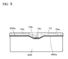
Fig. 5 ] A plan view of the liquid crystal display device showing the position of a gate port inFig. 4 . - [
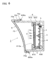
Fig. 6 ] An enlarged section view showing main portions inFig. 4 . - [
Fig. 7 ] An enlarged perspective view of main portions showing the position of a gate port provided for a see-through plate. - A liquid crystal display device according to the present invention is described in detail with an example of a liquid crystal display device used for a vehicle. In the following, embodiments of the present invention are described with reference to the drawings.
-
Fig. 1 to Fig. 3 show a first embodiment. A liquidcrystal display device 1 of the present embodiment includes aliquid crystal display 2 having a liquid crystal sealed in between a pair ofglass substrates plates glass substrate circuit substrate 3 having a driving circuit 3a mounted thereon for driving theliquid crystal display 2, alight source 4 formed of a light-emitting diode or the like, mounted on thecircuit substrate 3, and illuminating theliquid crystal display 2 for realizing display, aholder 5 holding theliquid crystal display 2 and thecircuit substrate 3, acasing 6 housing theliquid crystal display 2, thecircuit substrate 3, and theholder 5, and a see-throughplate 7 made, for example of acrylic resin, covering an opening portion on the front of thecasing 6, protecting the polarizingplate 2c placed on the front side of theliquid crystal display 2, preventing entry of dust from the outside to the inside of thecasing 6, and provided with an area for allowing visual recognition of a display portion area of theliquid crystal display 2. - The
casing 6 in the present embodiment is formed of acasing member 60 housing theliquid crystal display 2, thecircuit substrate 3, and theholder 5, and acasing member 61 in hood form placed on a front side of thecasing member 60 and provided with anopening portion 61a for visual recognition of the display portion area of theliquid crystal display 2. The see-throughplate 7 made of acrylic resin described above is provided on a front side of thecasing member 61 in hood form which constitutes part of thecasing 6. - The see-through
plate 7 is provided with aside wall 7a extending continuously in a direction substantially orthogonal to the area for visually recognizing theliquid crystal display 2 so as to surround the outside of an end portion of an opening portion on the front of the casing 6 (thecasing member 61 in hood form). Theside wall 7a has a protrudingportion 7b at a position located at a distance from the area for visually recognizing theliquid crystal display 2. Agate port 7c in resin molding of the see-throughplat 7 is provided at the position of the protrudingportion 7b. - In the present embodiment, the
protruding portion 7b of theside wall 7a provided with thegate port 7c has a generally trapezoidal shape tapered with thegate port 7c as a base point, as shown inFig. 1 andFig. 2 . - The area for visually recognizing the
liquid crystal display 2 on the front side of the see-throughplate 7 is formed in an arc curved shape R so that an observer is not confused when the observer visually recognizes theliquid crystal display 2 from the front side. - The
casing member 61 has a dust-preventative rib 61b integrally provided to protrude at a position opposite to the end face of theside wall 7a of the see-throughplate 7 so as to prevent entry of dust from between thecasing member 61 in hood form constituting part of thecasing 6 and the see-throughplate 7. - In the liquid crystal display according to the first embodiment configured in this manner, display contents (display information) on the
liquid crystal display 2 are illuminated transmissively from behind by light from thelight source 4. Since the front side of the see-throughplate 7 located at a position at a distance from thegate port 7c of the see-throughplate 7 has no anisotropy of refractive index due to molding (no limitation in direction), the light passes through the front side as it is, and the display contents on theliquid crystal display 2 can be visually recognized favorably even when it is seen through polarizing glasses. - When the display contents on the
liquid crystal display 2 are attempted to be checked through the polarizing glasses, thegate port 7c is provided at the position of the protrudingportion 7b at the position of theside wall 7a of the see-through 7 at a distance from the visible range of theliquid crystal display 2 and thus the refractive index is anisotropic only near thegate port 7c due to the molding stress produced in molding since, and as a result, the areas partially appearing black are only the protrudingportion 7b and theside wall 7a of the see-throughplate 7 coinciding with a direction orthogonal to the polarization axis of the polarizing glasses when viewed through the polarizing glasses. However, the other area or the front side of the see-throughplate 7 which is the area for visually recognizing theliquid crystal display 2 at the position at a distance from thegate port 7c has no anisotropy of refractive index due to the molding as described above (no limitation in direction), so that the light passes as it is, and the display contents on theliquid crystal display 2 can be favorably read and understood even when they are seen through the polarizing glasses. - In the present embodiment, the
protruding portion 7b formed to protrude from theside wall 7a provided with thegate port 7c is formed in the generally trapezoidal shape tapered with thegate port 7c as the base point. The formation of the protrudingportion 7b of theside wall 7a of the see-throughplate 7 in the generally trapezoidal shape tapered with thegate port 7c as the base point allows favorable resin fluidity in the molding of the synthetic resin material. As a result, the molding stress in the resin molding can be relieved to reduce the size of the area having anisotropy of refractive index due to the molding stress. - The generally trapezoidal shape tapered around the
gate port 7c can reduce the size of the area under the molding stress in the resin molding. When the display is seen through the polarizing glasses, the portion partially appearing black is only the narrow area (the area under the molding stress in the molding) of theside wall 7a of the see-throughplate 7 coinciding with the direction orthogonal to the polarization axis of the polarizing glasses, so that the depth dimension of theside wall 7a can be reduced. - The area for visually recognizing the
liquid crystal display 2 on the front side of the see-throughplate 7 is formed in the arc curved shape R to prevent confusion when the observer visually recognizes theliquid crystal display 2 from the front side. Even when external light is incident on the front side of theliquid crystal display 2 from the outside, the light rays are reflected on the see-throughplate 7 and then reflected in a horizontal direction (other than a line-of-vision direction) without returning to the line-of-vision direction because of the curved shape R of the arc shape, the display contents on theliquid crystal display 2 can be favorably recognized without confusion. - The
casing 6 has the dust-preventative rib 61b integrally provided to protrude at the position opposite to the end face of theside wall 7a of the see-throughplate 7. Even when dust is to enter from the end side of theside wall 7a of the see-through 7, the dust-preventative rib 61b formed to protrude from thecasing 6 can block the dust. - Specifically, the dust-
preventative rib 61b provided opposite to the end face of theside wall 7a of the see-throughplate 7 integrally with thecasing member 61 in hood form can prevent dust from entering from the gap portion serving as the boundary between theside wall 7a provided for the see-throughplate 7 and thecasing member 61. -
Fig. 4 to Fig. 7 shows a second embodiment of the present invention. Components identical to or equivalent to the components described in the first embodiment are designated and described with the same reference numerals. - In
Fig. 4 to Fig. 7 , substantially similarly to the first embodiment, a liquidcrystal display device 1 has aliquid crystal display 2, acircuit substrate 3 having alight source 4 mounted thereon, and aholder 5 which are housed in acasing 6, and also has a see-throughplate 70 made, for example of acrylic resin, covering an opening portion on the front of thecasing 6, protecting apolarizing plate 2c placed on a front side of theliquid crystal display 2, preventing entry of dust from the outside to the inside of thecasing 6, provided with an area for visually recognizing a display portion area of theliquid crystal display 2. - The
casing 6 in the present embodiment is formed of acasing member 600 housing theliquid crystal display 2, thecircuit substrate 3, and theholder 5, and acasing member 610 in frame form placed on a front side of theliquid crystal display 2 housed in thecasing member 600, closing the gap portion between the outside of the display area of theliquid crystal display 2 and an inner wall portion of thecasing member 600, provided with anopening portion 610a for visual recognition of the display portion area of theliquid crystal display 2. The see-throughplate 70 made of acrylic resin described above is provided on a front side of thecasing member 600 which constitutes part of thecasing 6. - The
casing member 600 has a dust-preventative rib 600a integrally provided to protrude at a position opposite to the end face of theside wall 70a of the see-throughplate 70 so as to prevent entry of dust from between the casingmember 600 and the see-through plate 700. - In the present embodiment, substantially similarly to the first embodiment described above, a protruding
portion 70b formed to protrude from theside wall 70a provided with thegate port 70c has a generally trapezoidal shape tapered with thegate port 70c as a base point. In addition, in the present embodiment, the thickness dimensions of thegate port 70c are formed such that the central portion is formed as a thin portion T1 and both end portions of the generally trapezoidal and tapered shape are formed as a thick portion T2. (SeeFig. 7 ) - In the present embodiment, the see-through
plate 70 is molded with coloring in a predetermined color by mixing black or brown pigments. - In the liquid crystal display according to the second embodiment configured in this manner, substantially similarly to the first embodiment, display contents (display information) on the
liquid crystal display 2 are illuminated transmissively from behind by light from thelight source 4. Since the front side of the see-throughplate 70 located at a position at a distance from thegate port 70c of the see-throughplate 7 has no anisotropy of refractive index due to molding (no limitation in direction), the light passes through the front side as it is, and the display contents on theliquid crystal display 2 can be visually recognized favorably even when it is seen through polarizing glasses. - In the present embodiment, since the protruding
portion 70b formed to protrude from theside wall 70a provided with thegate port 70c is formed in the generally trapezoidal shape tapered with thegate port 70c as the base point, and the thickness dimensions of thegate port 70c are formed such that the central portion is formed as the thin portion T1 and both end portions of the generally trapezoidal and tapered shape are formed as the thick portion T2, the generally trapezoidal shape tapered with thegate port 70c as the base point allows favorable resin fluidity in the molding of the synthetic resin material substantially similarly to the first embodiment described above. As a result, the molding stress in the resin molding can be relieved to reduce the size of the area having anisotropy of refractive index due to the molding stress. In addition, since the thickness dimensions of thegate port 70c are formed such that the central portion is formed as the thin portion T1 and both end portions are formed as the thick portion T2, the flow of the resin in the molding is enhanced on both sides as compared with the central portion to allow uniform flow over the entire see-throughplate 7 in the resin molding. - Thus, the resin fluidity in the molding of the synthetic resin material can be enhanced and the flow in the resin molding can be uniformalized. As a result, the molding stress can be relieved to reduce the size of the area where the orientation direction of the resin molecules is nonuniform. This can widen the area with the proper orientation direction of the molecules in the resin molding relative to the polarization axis direction of the polarizing plate of the liquid crystal display.
- Since the see-through
plate 70 itself is molded with coloring in a predetermined color by mixing black or brown pigments, the color of the display portion of theliquid crystal display 2 transmitted through the see-throughplate 70 is entirely illuminated through the color of the see-throughplate 70, and theliquid crystal display 2 appears to be placed at a position behind the see-throughplate 70, so that a sense of greater depth and a three-dimensional appearance can be enhanced. In addition, since thecasing member 610 in frame form covering the outer peripheral portion of theliquid crystal display 2 is visually recognized through the colored see-throughplate 70, only theliquid crystal display 2 appears to be isolated against a dark background. Thus, theliquid crystal display 1 with favorable appearance can be provided. - Similarly to the first embodiment described above, since the see-through
plate 70 is formed in the arc curved shape R, light rays are reflected on the see-throughplate 70 and then reflected in the horizontal direction other than the line-of-vision direction without returning to the line-of-vision direction, so that the display contents on theliquid crystal display 2 can be favorably recognized. In addition, thecasing 600 has the dust-preventative rib 600a integrally provided to protrude at the position opposite to the end face of theside wall 70a of the see-throughplate 70. Even when dust is to enter from the end portion of theside wall 70a of the see-through 70, the dust-preventative rib 600a formed to protrude from thecasing 600 can block the dust. - The present invention is not limited to the embodiments described above, and various modification can be made without departing from the spirit or scope of the present invention. For example, the protruding
portions side walls plates gate ports gate ports gate ports portions side walls plates gate ports portions plates - As described in detail in the embodiments or the like described above, the liquid crystal display device has been described with the example of an indicator for a vehicle such as a car. However, the present invention is not limited to the indicator for vehicle but is applicable to an indicator for a ship, or an indicator for a special vehicle such as an agricultural machine and a construction machine, or a liquid crystal display provided for a remote-control operation panel of a water heater or the like, or a commercial device such as a videocassette recorder and an audio product.
-
- R
- CURVED SHAPE
- T1
- THIN PORTION
- T2
- THICK PORTION
- 1
- LIQUID CRYSTAL DISPLAY DEVICE
- 2
- LIQUID CRYSTAL DISPLAY
- 2a, 2b
- GLASS SUBSTRATE
- 2c, 2d
- POLARIZING PLATE
- 3
- CIRCUIT SUBSTRATE
- 3a
- DRIVING CIRCUIT
- 4
- LIGHT SOURCE (LIGHT-EMITTING DIODE)
- 5
- HOLDER
- 6
- CASING
- 7
- SEE-THROUGH PLATE
- 7a
- SIDE WALL
- 7b
- PROTRUDING PORTION
- 7c
- GATE PORT
- 60
- CASING MEMBER
- 61
- CASING MEMBER IN HOOD FORM
- 61a
- OPENING PORTION
- 61b
- DUST-PREVENTATIVE RIB
- 70
- SEE-THROUGH PLATE
- 70a
- SIDE WALL
- 70b
- PROTRUDING PORTION
- 70c
- GATE PORT
- 600
- CASING MEMBER
- 600a
- DUST-PREVENTATIVE RIB
- 610
- CASING MEMBER IN FRAME FORM
- 610a
- OPENING PORTION
Claims (6)
- A liquid crystal display device comprising a liquid crystal display including a polarizing plate provided on each of a front side and a rear side, a casing housing the liquid crystal display, and a see-through plate made of synthetic resin, covering an opening portion on a front of the casing, and provided for visual recognition of a display portion area of the liquid crystal display, characterized in that the see-through plate is provided with a side wall extending continuously from an area for visually recognizing the liquid crystal display so as to surround an outside of an end portion of the opening portion on the front of the casing, and the side wall is provided with a gate port in molding of a resin of the see-through plate at a position located at a distance from the area for visually recognizing the liquid crystal display.
- The liquid crystal display device according to claim 1, characterized in that the side wall is provided with a protruding portion at a position located at a distance from the area for visually recognizing the liquid crystal display, and the gate port in molding of the resin of the see-through plate is provided at a position of the protruding portion.
- The liquid crystal display device according to claim 2, characterized in that the protruding portion protruding from the side wall provided with the gate port is formed in a generally trapezoidal shape tapered with the gate port as a base point.
- The liquid crystal display device according to any one of claims 1 to 3, characterized in that a dust-preventative rib is formed to protrude opposite to a position of an end portion of the side wall and integrally with the casing.
- The liquid crystal display device according to any one of claims 1 to 4, characterized in that the see-through plate is colored and molded.
- The liquid crystal display device according to any one of claims 1 to 5, characterized in that the area for visually recognizing the liquid crystal display on the front side of the see-through plate is formed in an arc curved shape.
Applications Claiming Priority (2)
| Application Number | Priority Date | Filing Date | Title |
|---|---|---|---|
| JP2009213971A JP5311048B2 (en) | 2009-09-16 | 2009-09-16 | Liquid crystal display |
| PCT/JP2010/063968 WO2011033893A1 (en) | 2009-09-16 | 2010-08-19 | Liquid crystal display device |
Publications (3)
| Publication Number | Publication Date |
|---|---|
| EP2479602A1 true EP2479602A1 (en) | 2012-07-25 |
| EP2479602A4 EP2479602A4 (en) | 2013-03-13 |
| EP2479602B1 EP2479602B1 (en) | 2014-04-02 |
Family
ID=43758506
Family Applications (1)
| Application Number | Title | Priority Date | Filing Date |
|---|---|---|---|
| EP10817006.9A Active EP2479602B1 (en) | 2009-09-16 | 2010-08-19 | Liquid crystal display device |
Country Status (6)
| Country | Link |
|---|---|
| US (1) | US8681287B2 (en) |
| EP (1) | EP2479602B1 (en) |
| JP (1) | JP5311048B2 (en) |
| KR (1) | KR101654961B1 (en) |
| CN (1) | CN102498433B (en) |
| WO (1) | WO2011033893A1 (en) |
Families Citing this family (8)
| Publication number | Priority date | Publication date | Assignee | Title |
|---|---|---|---|---|
| CN102501767B (en) * | 2011-11-04 | 2015-07-15 | 博世汽车多媒体(芜湖)有限公司 | Liquid crystal display (LCD) screen module applied to automobile meter |
| JP5938333B2 (en) * | 2012-11-06 | 2016-06-22 | アルパイン株式会社 | Display device |
| JP5962719B2 (en) * | 2013-09-17 | 2016-08-03 | 株式会社デンソー | Vehicle display device |
| US9757354B2 (en) * | 2015-06-08 | 2017-09-12 | Regents Of The University Of Minnesota | Therapeutic formulations and methods |
| CN106143155A (en) * | 2016-07-08 | 2016-11-23 | 吕冬芳 | The colored full liquid crystal display automobile instrument of a kind of double screen stack combinations |
| JP6933002B2 (en) * | 2017-06-06 | 2021-09-08 | 日本精機株式会社 | Display device |
| JP7376444B2 (en) * | 2020-09-17 | 2023-11-08 | トヨタ自動車株式会社 | vehicle structure |
| JP7436414B2 (en) * | 2021-03-26 | 2024-02-21 | トヨタ自動車株式会社 | vehicle structure |
Citations (4)
| Publication number | Priority date | Publication date | Assignee | Title |
|---|---|---|---|---|
| JPH11240355A (en) * | 1998-02-26 | 1999-09-07 | Nippon Seiki Kk | Vehicular meter device |
| JP2000219060A (en) * | 1999-01-29 | 2000-08-08 | Nippon Seiki Co Ltd | Display |
| JP2001260168A (en) * | 2000-03-14 | 2001-09-25 | Yoshida Industry Co Ltd | Method for manufacturing protective panel for display window of electronic instrument |
| JP2005291718A (en) * | 2004-03-31 | 2005-10-20 | Nippon Seiki Co Ltd | Luminous display device |
Family Cites Families (5)
| Publication number | Priority date | Publication date | Assignee | Title |
|---|---|---|---|---|
| JPH0465319A (en) | 1990-07-04 | 1992-03-02 | Matsushita Electric Ind Co Ltd | Production of oxide superconducting material |
| JPH0465319U (en) | 1990-10-17 | 1992-06-05 | ||
| JPH10214036A (en) | 1997-01-29 | 1998-08-11 | Denso Corp | Display device |
| US6411216B1 (en) * | 1999-01-25 | 2002-06-25 | Nippon Seiki Co., Ltd. | Display device with indicators having increased brightness |
| JP5094331B2 (en) * | 2007-10-22 | 2012-12-12 | 株式会社日立製作所 | Display device |
-
2009
- 2009-09-16 JP JP2009213971A patent/JP5311048B2/en active Active
-
2010
- 2010-08-19 US US13/394,522 patent/US8681287B2/en active Active
- 2010-08-19 KR KR1020127008123A patent/KR101654961B1/en active IP Right Grant
- 2010-08-19 CN CN201080041571.XA patent/CN102498433B/en not_active Expired - Fee Related
- 2010-08-19 EP EP10817006.9A patent/EP2479602B1/en active Active
- 2010-08-19 WO PCT/JP2010/063968 patent/WO2011033893A1/en active Application Filing
Patent Citations (4)
| Publication number | Priority date | Publication date | Assignee | Title |
|---|---|---|---|---|
| JPH11240355A (en) * | 1998-02-26 | 1999-09-07 | Nippon Seiki Kk | Vehicular meter device |
| JP2000219060A (en) * | 1999-01-29 | 2000-08-08 | Nippon Seiki Co Ltd | Display |
| JP2001260168A (en) * | 2000-03-14 | 2001-09-25 | Yoshida Industry Co Ltd | Method for manufacturing protective panel for display window of electronic instrument |
| JP2005291718A (en) * | 2004-03-31 | 2005-10-20 | Nippon Seiki Co Ltd | Luminous display device |
Non-Patent Citations (1)
| Title |
|---|
| See also references of WO2011033893A1 * |
Also Published As
| Publication number | Publication date |
|---|---|
| CN102498433A (en) | 2012-06-13 |
| JP5311048B2 (en) | 2013-10-09 |
| EP2479602B1 (en) | 2014-04-02 |
| EP2479602A4 (en) | 2013-03-13 |
| KR20120073257A (en) | 2012-07-04 |
| CN102498433B (en) | 2015-02-25 |
| US8681287B2 (en) | 2014-03-25 |
| WO2011033893A1 (en) | 2011-03-24 |
| KR101654961B1 (en) | 2016-09-06 |
| US20120162571A1 (en) | 2012-06-28 |
| JP2011064840A (en) | 2011-03-31 |
Similar Documents
| Publication | Publication Date | Title |
|---|---|---|
| EP2479602B1 (en) | Liquid crystal display device | |
| EP3197136B1 (en) | Display screen assembly, front cover of terminal, and terminal | |
| EP2960631B1 (en) | Display device | |
| US9983347B2 (en) | Display device | |
| US9574913B2 (en) | Dial plate structure and automotive meter | |
| KR20120036283A (en) | Back-light device and liquid crystal display device | |
| EP2985751B1 (en) | Display device | |
| US20140376257A1 (en) | Operating panel and information apparatus provided with same | |
| WO2013140464A1 (en) | Electronic device | |
| JP4706898B2 (en) | Display device | |
| JP2016095398A (en) | Display | |
| US11285811B2 (en) | Vehicle display device pointer | |
| JP2017032707A (en) | Display device | |
| CN103837186A (en) | Pointer structure | |
| JP2019113322A (en) | Vehicle meter | |
| JP2010247630A (en) | Reflecting member and head-up display device using the same | |
| JP7008263B2 (en) | Vehicle instruments | |
| JP2008203487A (en) | Electronic equipment with lighting | |
| JPH0348726A (en) | Pointer for vehicle display device | |
| JP2014228356A (en) | Display device for vehicle | |
| JP6116204B2 (en) | Guideline structure | |
| JP3491730B2 (en) | Vehicle instrument | |
| US9434254B2 (en) | Display device | |
| JP2011226838A (en) | Measuring apparatus for vehicle | |
| JP2008171772A (en) | Vehicle meter device |
Legal Events
| Date | Code | Title | Description |
|---|---|---|---|
| PUAI | Public reference made under article 153(3) epc to a published international application that has entered the european phase |
Free format text: ORIGINAL CODE: 0009012 |
|
| 17P | Request for examination filed |
Effective date: 20120313 |
|
| AK | Designated contracting states |
Kind code of ref document: A1 Designated state(s): AL AT BE BG CH CY CZ DE DK EE ES FI FR GB GR HR HU IE IS IT LI LT LU LV MC MK MT NL NO PL PT RO SE SI SK SM TR |
|
| DAX | Request for extension of the european patent (deleted) | ||
| A4 | Supplementary search report drawn up and despatched |
Effective date: 20130207 |
|
| RIC1 | Information provided on ipc code assigned before grant |
Ipc: B60K 37/00 20060101ALI20130201BHEP Ipc: B60K 35/00 20060101AFI20130201BHEP |
|
| REG | Reference to a national code |
Ref country code: DE Ref legal event code: R079 Ref document number: 602010014912 Country of ref document: DE Free format text: PREVIOUS MAIN CLASS: G02F0001133300 Ipc: B60K0035000000 |
|
| GRAP | Despatch of communication of intention to grant a patent |
Free format text: ORIGINAL CODE: EPIDOSNIGR1 |
|
| RIC1 | Information provided on ipc code assigned before grant |
Ipc: B60K 37/02 20060101ALI20130918BHEP Ipc: B60K 35/00 20060101AFI20130918BHEP Ipc: B60K 37/00 20060101ALI20130918BHEP |
|
| INTG | Intention to grant announced |
Effective date: 20131018 |
|
| GRAS | Grant fee paid |
Free format text: ORIGINAL CODE: EPIDOSNIGR3 |
|
| GRAA | (expected) grant |
Free format text: ORIGINAL CODE: 0009210 |
|
| AK | Designated contracting states |
Kind code of ref document: B1 Designated state(s): AL AT BE BG CH CY CZ DE DK EE ES FI FR GB GR HR HU IE IS IT LI LT LU LV MC MK MT NL NO PL PT RO SE SI SK SM TR |
|
| REG | Reference to a national code |
Ref country code: GB Ref legal event code: FG4D |
|
| REG | Reference to a national code |
Ref country code: CH Ref legal event code: EP Ref country code: AT Ref legal event code: REF Ref document number: 659864 Country of ref document: AT Kind code of ref document: T Effective date: 20140415 |
|
| REG | Reference to a national code |
Ref country code: IE Ref legal event code: FG4D |
|
| REG | Reference to a national code |
Ref country code: DE Ref legal event code: R096 Ref document number: 602010014912 Country of ref document: DE Effective date: 20140515 |
|
| REG | Reference to a national code |
Ref country code: AT Ref legal event code: MK05 Ref document number: 659864 Country of ref document: AT Kind code of ref document: T Effective date: 20140402 |
|
| REG | Reference to a national code |
Ref country code: NL Ref legal event code: VDEP Effective date: 20140402 |
|
| REG | Reference to a national code |
Ref country code: LT Ref legal event code: MG4D |
|
| PG25 | Lapsed in a contracting state [announced via postgrant information from national office to epo] |
Ref country code: NO Free format text: LAPSE BECAUSE OF FAILURE TO SUBMIT A TRANSLATION OF THE DESCRIPTION OR TO PAY THE FEE WITHIN THE PRESCRIBED TIME-LIMIT Effective date: 20140702 Ref country code: CY Free format text: LAPSE BECAUSE OF FAILURE TO SUBMIT A TRANSLATION OF THE DESCRIPTION OR TO PAY THE FEE WITHIN THE PRESCRIBED TIME-LIMIT Effective date: 20140402 Ref country code: LT Free format text: LAPSE BECAUSE OF FAILURE TO SUBMIT A TRANSLATION OF THE DESCRIPTION OR TO PAY THE FEE WITHIN THE PRESCRIBED TIME-LIMIT Effective date: 20140402 Ref country code: GR Free format text: LAPSE BECAUSE OF FAILURE TO SUBMIT A TRANSLATION OF THE DESCRIPTION OR TO PAY THE FEE WITHIN THE PRESCRIBED TIME-LIMIT Effective date: 20140703 Ref country code: IS Free format text: LAPSE BECAUSE OF FAILURE TO SUBMIT A TRANSLATION OF THE DESCRIPTION OR TO PAY THE FEE WITHIN THE PRESCRIBED TIME-LIMIT Effective date: 20140802 Ref country code: FI Free format text: LAPSE BECAUSE OF FAILURE TO SUBMIT A TRANSLATION OF THE DESCRIPTION OR TO PAY THE FEE WITHIN THE PRESCRIBED TIME-LIMIT Effective date: 20140402 Ref country code: BG Free format text: LAPSE BECAUSE OF FAILURE TO SUBMIT A TRANSLATION OF THE DESCRIPTION OR TO PAY THE FEE WITHIN THE PRESCRIBED TIME-LIMIT Effective date: 20140702 Ref country code: NL Free format text: LAPSE BECAUSE OF FAILURE TO SUBMIT A TRANSLATION OF THE DESCRIPTION OR TO PAY THE FEE WITHIN THE PRESCRIBED TIME-LIMIT Effective date: 20140402 Ref country code: CZ Free format text: LAPSE BECAUSE OF FAILURE TO SUBMIT A TRANSLATION OF THE DESCRIPTION OR TO PAY THE FEE WITHIN THE PRESCRIBED TIME-LIMIT Effective date: 20140402 |
|
| PG25 | Lapsed in a contracting state [announced via postgrant information from national office to epo] |
Ref country code: PL Free format text: LAPSE BECAUSE OF FAILURE TO SUBMIT A TRANSLATION OF THE DESCRIPTION OR TO PAY THE FEE WITHIN THE PRESCRIBED TIME-LIMIT Effective date: 20140402 Ref country code: LV Free format text: LAPSE BECAUSE OF FAILURE TO SUBMIT A TRANSLATION OF THE DESCRIPTION OR TO PAY THE FEE WITHIN THE PRESCRIBED TIME-LIMIT Effective date: 20140402 Ref country code: ES Free format text: LAPSE BECAUSE OF FAILURE TO SUBMIT A TRANSLATION OF THE DESCRIPTION OR TO PAY THE FEE WITHIN THE PRESCRIBED TIME-LIMIT Effective date: 20140402 Ref country code: SE Free format text: LAPSE BECAUSE OF FAILURE TO SUBMIT A TRANSLATION OF THE DESCRIPTION OR TO PAY THE FEE WITHIN THE PRESCRIBED TIME-LIMIT Effective date: 20140402 Ref country code: AT Free format text: LAPSE BECAUSE OF FAILURE TO SUBMIT A TRANSLATION OF THE DESCRIPTION OR TO PAY THE FEE WITHIN THE PRESCRIBED TIME-LIMIT Effective date: 20140402 Ref country code: HR Free format text: LAPSE BECAUSE OF FAILURE TO SUBMIT A TRANSLATION OF THE DESCRIPTION OR TO PAY THE FEE WITHIN THE PRESCRIBED TIME-LIMIT Effective date: 20140402 |
|
| PG25 | Lapsed in a contracting state [announced via postgrant information from national office to epo] |
Ref country code: PT Free format text: LAPSE BECAUSE OF FAILURE TO SUBMIT A TRANSLATION OF THE DESCRIPTION OR TO PAY THE FEE WITHIN THE PRESCRIBED TIME-LIMIT Effective date: 20140804 |
|
| REG | Reference to a national code |
Ref country code: DE Ref legal event code: R097 Ref document number: 602010014912 Country of ref document: DE |
|
| PG25 | Lapsed in a contracting state [announced via postgrant information from national office to epo] |
Ref country code: SK Free format text: LAPSE BECAUSE OF FAILURE TO SUBMIT A TRANSLATION OF THE DESCRIPTION OR TO PAY THE FEE WITHIN THE PRESCRIBED TIME-LIMIT Effective date: 20140402 Ref country code: EE Free format text: LAPSE BECAUSE OF FAILURE TO SUBMIT A TRANSLATION OF THE DESCRIPTION OR TO PAY THE FEE WITHIN THE PRESCRIBED TIME-LIMIT Effective date: 20140402 Ref country code: DK Free format text: LAPSE BECAUSE OF FAILURE TO SUBMIT A TRANSLATION OF THE DESCRIPTION OR TO PAY THE FEE WITHIN THE PRESCRIBED TIME-LIMIT Effective date: 20140402 Ref country code: BE Free format text: LAPSE BECAUSE OF FAILURE TO SUBMIT A TRANSLATION OF THE DESCRIPTION OR TO PAY THE FEE WITHIN THE PRESCRIBED TIME-LIMIT Effective date: 20140402 Ref country code: RO Free format text: LAPSE BECAUSE OF FAILURE TO SUBMIT A TRANSLATION OF THE DESCRIPTION OR TO PAY THE FEE WITHIN THE PRESCRIBED TIME-LIMIT Effective date: 20140402 |
|
| PLBE | No opposition filed within time limit |
Free format text: ORIGINAL CODE: 0009261 |
|
| STAA | Information on the status of an ep patent application or granted ep patent |
Free format text: STATUS: NO OPPOSITION FILED WITHIN TIME LIMIT |
|
| 26N | No opposition filed |
Effective date: 20150106 |
|
| PG25 | Lapsed in a contracting state [announced via postgrant information from national office to epo] |
Ref country code: MC Free format text: LAPSE BECAUSE OF FAILURE TO SUBMIT A TRANSLATION OF THE DESCRIPTION OR TO PAY THE FEE WITHIN THE PRESCRIBED TIME-LIMIT Effective date: 20140402 Ref country code: LU Free format text: LAPSE BECAUSE OF FAILURE TO SUBMIT A TRANSLATION OF THE DESCRIPTION OR TO PAY THE FEE WITHIN THE PRESCRIBED TIME-LIMIT Effective date: 20140819 Ref country code: IT Free format text: LAPSE BECAUSE OF FAILURE TO SUBMIT A TRANSLATION OF THE DESCRIPTION OR TO PAY THE FEE WITHIN THE PRESCRIBED TIME-LIMIT Effective date: 20140402 |
|
| REG | Reference to a national code |
Ref country code: CH Ref legal event code: PL |
|
| REG | Reference to a national code |
Ref country code: DE Ref legal event code: R097 Ref document number: 602010014912 Country of ref document: DE Effective date: 20150106 |
|
| PG25 | Lapsed in a contracting state [announced via postgrant information from national office to epo] |
Ref country code: CH Free format text: LAPSE BECAUSE OF NON-PAYMENT OF DUE FEES Effective date: 20140831 Ref country code: LI Free format text: LAPSE BECAUSE OF NON-PAYMENT OF DUE FEES Effective date: 20140831 |
|
| REG | Reference to a national code |
Ref country code: IE Ref legal event code: MM4A |
|
| PG25 | Lapsed in a contracting state [announced via postgrant information from national office to epo] |
Ref country code: SI Free format text: LAPSE BECAUSE OF FAILURE TO SUBMIT A TRANSLATION OF THE DESCRIPTION OR TO PAY THE FEE WITHIN THE PRESCRIBED TIME-LIMIT Effective date: 20140402 |
|
| PG25 | Lapsed in a contracting state [announced via postgrant information from national office to epo] |
Ref country code: IE Free format text: LAPSE BECAUSE OF NON-PAYMENT OF DUE FEES Effective date: 20140819 |
|
| PG25 | Lapsed in a contracting state [announced via postgrant information from national office to epo] |
Ref country code: SM Free format text: LAPSE BECAUSE OF FAILURE TO SUBMIT A TRANSLATION OF THE DESCRIPTION OR TO PAY THE FEE WITHIN THE PRESCRIBED TIME-LIMIT Effective date: 20140402 |
|
| PG25 | Lapsed in a contracting state [announced via postgrant information from national office to epo] |
Ref country code: MT Free format text: LAPSE BECAUSE OF FAILURE TO SUBMIT A TRANSLATION OF THE DESCRIPTION OR TO PAY THE FEE WITHIN THE PRESCRIBED TIME-LIMIT Effective date: 20140402 |
|
| REG | Reference to a national code |
Ref country code: FR Ref legal event code: PLFP Year of fee payment: 7 |
|
| PG25 | Lapsed in a contracting state [announced via postgrant information from national office to epo] |
Ref country code: HU Free format text: LAPSE BECAUSE OF FAILURE TO SUBMIT A TRANSLATION OF THE DESCRIPTION OR TO PAY THE FEE WITHIN THE PRESCRIBED TIME-LIMIT; INVALID AB INITIO Effective date: 20100819 Ref country code: TR Free format text: LAPSE BECAUSE OF FAILURE TO SUBMIT A TRANSLATION OF THE DESCRIPTION OR TO PAY THE FEE WITHIN THE PRESCRIBED TIME-LIMIT Effective date: 20140402 |
|
| REG | Reference to a national code |
Ref country code: FR Ref legal event code: PLFP Year of fee payment: 8 |
|
| PG25 | Lapsed in a contracting state [announced via postgrant information from national office to epo] |
Ref country code: MK Free format text: LAPSE BECAUSE OF FAILURE TO SUBMIT A TRANSLATION OF THE DESCRIPTION OR TO PAY THE FEE WITHIN THE PRESCRIBED TIME-LIMIT Effective date: 20140402 |
|
| REG | Reference to a national code |
Ref country code: FR Ref legal event code: PLFP Year of fee payment: 9 |
|
| PG25 | Lapsed in a contracting state [announced via postgrant information from national office to epo] |
Ref country code: AL Free format text: LAPSE BECAUSE OF FAILURE TO SUBMIT A TRANSLATION OF THE DESCRIPTION OR TO PAY THE FEE WITHIN THE PRESCRIBED TIME-LIMIT Effective date: 20140402 |
|
| PGFP | Annual fee paid to national office [announced via postgrant information from national office to epo] |
Ref country code: GB Payment date: 20220630 Year of fee payment: 13 |
|
| PGFP | Annual fee paid to national office [announced via postgrant information from national office to epo] |
Ref country code: FR Payment date: 20220709 Year of fee payment: 13 |
|
| PGFP | Annual fee paid to national office [announced via postgrant information from national office to epo] |
Ref country code: DE Payment date: 20230627 Year of fee payment: 14 |