JP2016095398A - Display - Google Patents
Display Download PDFInfo
- Publication number
- JP2016095398A JP2016095398A JP2014231542A JP2014231542A JP2016095398A JP 2016095398 A JP2016095398 A JP 2016095398A JP 2014231542 A JP2014231542 A JP 2014231542A JP 2014231542 A JP2014231542 A JP 2014231542A JP 2016095398 A JP2016095398 A JP 2016095398A
- Authority
- JP
- Japan
- Prior art keywords
- display element
- case
- protective panel
- display device
- side end
- Prior art date
- Legal status (The legal status is an assumption and is not a legal conclusion. Google has not performed a legal analysis and makes no representation as to the accuracy of the status listed.)
- Pending
Links
Images


Abstract
Description
本発明は、表示素子を備えた表示装置に関するものである。 The present invention relates to a display device provided with a display element.
液晶表示素子を備えた表示装置が提案されており、例えば特許文献1に開示されている。斯かる表示装置は、上ケースに設けた開口部と液晶表示素子との間に保護パネルと光学弾性体を接着することにより、表示装置を保護するものである。
A display device including a liquid crystal display element has been proposed, and is disclosed in, for example,
しかしながら、特許文献1に記載の表示装置においては、下ケースを上ケースが覆う形状であるため、表示装置全体の額縁が広い点で改善の余地があった。
However, in the display device described in
本発明は、表示装置の額縁を狭くすることが可能であり、優れた外観品位を有する表示装置を提供するものである。 The present invention provides a display device that can narrow the frame of the display device and has excellent appearance quality.
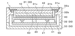
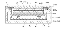
本発明は、表示素子10と、前記表示素子10と電気的に接続される回路基板20と、前記表示素子10及び前記回路基板20を収容するケース部材30と、を備えた表示装置であって、前記ケース部材30は、傾斜面からなる側端面31aを有し前記表示素子10の前面に取り付けられた保護パネル31と、前記保護パネル31の前記側端面31aに接合された傾斜面32aを有するケース体32と、を有することを特徴とする。
The present invention is a display device comprising a
また、本発明は、前記保護パネル31が接合された前記ケース体32の前面が、平坦であることを特徴とする。
Further, the present invention is characterized in that the front surface of the
また、本発明は、前記保護パネル31の側端面31aまたは前記ケース体32の傾斜面32aに、遮光層または加飾部を備えてなることを特徴とする。
Further, the present invention is characterized in that a light shielding layer or a decorative portion is provided on the
保護パネルの側端面を傾斜面にすることにより、表示装置の額縁を狭くすることができる。 By making the side end surface of the protective panel an inclined surface, the frame of the display device can be narrowed.
以下、添付図面を用いて、本発明の一実施形態を説明する。 Hereinafter, an embodiment of the present invention will be described with reference to the accompanying drawings.
表示装置1は、液晶表示素子10と、回路基板20と、ケース部材30と、導光体40と中ケース50で主に構成され、自動車,オートバイ,農業機械,建設機械,船舶等の計器として用いられる。
The
液晶表示素子10は、透明電極が形成された一対のガラス基板に液晶を封入した液晶セルの前後両面に偏光板を貼付した液晶パネルからなるものである。液晶表示素子10と回路基板20とは、配線部材60によって電気的に接続される。回路基板20は、外部コネクタが実装されており、車両側と電気的に接続される。表示装置1は、外部コネクタ及び回路基板20上のインタフェース回路22を介して電源や車両情報に関する信号等を入力され、これらの信号等に基づいて、制御素子23を含む表示駆動回路24、照明駆動回路25により処理を行い、液晶表示素子10にて所定の表示を行い、発光素子21にて所定の照明光を発することができる。
The liquid
透明樹脂からなる導光体40は、受光部41と導光部42から構成される。中ケース50は、白色樹脂を適用することができる。中ケース50の上部には、導光体40の導光部42、液晶表示素子10が順次載置されている。導光体40は、中ケース50に固定されている。導光体40は、発光素子21が発した照明光を受光部41により受光し、導光部42により液晶表示素子10の背面に導く。導光体40の背面に導かれた照明光は、中ケース50により反射され、液晶表示素子10を透過照明する。中ケース50は上ケース32に固定される。中ケース50の下部には、回路基板20が固定される。
The
ケース部材30は、保護パネル31と上ケース32と下ケース33で構成される。保護パネル31には、透光性の無機ガラスを適用することができ、表面側に指標部を備えていても良い。保護パネル31は、後面側がすぼんだ等脚台形であり、傾斜面からなる側端面31aが設けられる。液晶表示素子10は無色透明で接着作用を持つ透過性接着剤31cを介して保護パネル31の後面にオプティカルボンディングにより固定される。界面反射を抑えるために、保護パネル31と透光性接着剤31cとは同等の屈折率を有するものが用いられる。保護パネル31後面の、表示素子10が固定された以外の箇所には、光を透過しない遮光層31bが設けられており、液晶表示素子10による表示以外は保護パネル31の前面から視認できなくなっている。遮光層31bは黒色インクの3層構造である。また、遮光層31bの代わりに意匠を配置しても良い。
The
上ケース32は合成樹脂材を適用することができ、前面、後面ともに開口されている。上ケース32の前面開口部付近には、保護パネル31の側端面31aに対応した勾配を有する傾斜面32aが設けられる。保護パネル31は上ケース32の傾斜面32aに誘導され、接着層32bによって上ケース32に固定される。保護パネル31と上ケース32は、上ケース32前面を基準として平坦となる。図3に示すように、上ケース32に突部を設け保護パネル31を支持する軸とし、周辺に接着層32bを配置しても良い。保護パネル31の前面外周と上ケース32の前面開口部外周とは、ほぼ同じ大きさでも良く、保護パネル31の前面外周がやや短くても良い。保護パネル31の前面外周が短い場合は、図4に示すように両者の隙間は充填剤32cで充填される。側端面31a及び傾斜面32aに勾配が設けられていることにより、上ケース32側面全体の厚みを適切に保ったまま、狭額縁化が可能となる。保護パネル31の側端面31a全体が上ケース32で覆われていることにより、落下等の衝撃によって保護パネル31が欠ける虞が少なくなる。また、側端面31a,傾斜面32aに意匠を配置することにより、実際より狭額縁であるかのような視覚効果が得られる。意匠は保護パネル31と上ケース32のどちら側に設けても良い。
A synthetic resin material can be applied to the
下ケース33は、合成樹脂材を適用することができ、前面を開口し、上ケース32の後面に固定される。上下ケース32,33の内部に生じる空洞部分に、上ケース32に固定された液晶表示素子10、中ケース50、回路基板20が格納される。上ケース32と下ケース33の接合面に溝を設け、パッキン部材を挟持し、上下ケース32,33を螺子締めすることにより、表示装置1を密閉構造にすることができる。
A synthetic resin material can be applied to the
このような構成によって、ケース全体の厚みを適切に保ったまま、表示装置の額縁を狭くすることできる。 With such a configuration, the frame of the display device can be narrowed while maintaining the thickness of the entire case appropriately.
したがって、外部からの衝撃に強く、優れた外観品位を有する表示装置を提供することができる。 Therefore, it is possible to provide a display device that is resistant to external impact and has excellent appearance quality.
なお、本発明は、上述した実施形態に限定されるものではなく、種々の変形が可能である。例えば、表示素子10は液晶表示素子であったが、有機EL等の自発光型の表示素子も適用できる。また、保護パネル31は無機ガラスであったが、透光性樹脂も適用できる。図5に示すように、液晶表示素子10と透過性接着剤31cの間に、タッチパネル70を備えることもできる。
In addition, this invention is not limited to embodiment mentioned above, A various deformation | transformation is possible. For example, although the
10 液晶表示素子(表示素子)
20 回路基板
21 発光素子
22 インタフェース回路
23 制御素子
24 表示駆動回路
25 照明駆動回路
30 ケース部材
31 保護パネル
31a 側端面
31b 遮光層
31c 透過性接着剤
32 上ケース(ケース体)
32a 傾斜面
32b 接着層
32c 充填剤
33 下ケース
40 導光体
41 受光部
42 導光部
50 中ケース
60 配線部材
70 タッチパネル
10 Liquid crystal display elements (display elements)
DESCRIPTION OF
32a Inclined
Claims (3)
前記ケース部材は、傾斜面からなる側端面を有し前記表示素子の前面に取り付けられた保護パネルと、前記保護パネルの前記側端面に接合された傾斜面を有するケース体と、を有することを特徴とする表示装置。 A display device comprising: a display element; a circuit board electrically connected to the display element; and a case member that houses the display element and the circuit board,
The case member includes a protective panel having a side end surface made of an inclined surface and attached to the front surface of the display element, and a case body having an inclined surface joined to the side end surface of the protective panel. Characteristic display device.
Priority Applications (1)
| Application Number | Priority Date | Filing Date | Title |
|---|---|---|---|
| JP2014231542A JP2016095398A (en) | 2014-11-14 | 2014-11-14 | Display |
Applications Claiming Priority (1)
| Application Number | Priority Date | Filing Date | Title |
|---|---|---|---|
| JP2014231542A JP2016095398A (en) | 2014-11-14 | 2014-11-14 | Display |
Publications (2)
| Publication Number | Publication Date |
|---|---|
| JP2016095398A true JP2016095398A (en) | 2016-05-26 |
| JP2016095398A5 JP2016095398A5 (en) | 2017-11-09 |
Family
ID=56071691
Family Applications (1)
| Application Number | Title | Priority Date | Filing Date |
|---|---|---|---|
| JP2014231542A Pending JP2016095398A (en) | 2014-11-14 | 2014-11-14 | Display |
Country Status (1)
| Country | Link |
|---|---|
| JP (1) | JP2016095398A (en) |
Cited By (3)
| Publication number | Priority date | Publication date | Assignee | Title |
|---|---|---|---|---|
| JP2018159617A (en) * | 2017-03-23 | 2018-10-11 | 日本精機株式会社 | Display device |
| CN111212529A (en) * | 2018-11-22 | 2020-05-29 | 北京小米移动软件有限公司 | Mobile terminal shell, preparation method thereof and mobile terminal |
| WO2023240439A1 (en) * | 2022-06-14 | 2023-12-21 | 京东方科技集团股份有限公司 | Oled display module and display device |
Citations (6)
| Publication number | Priority date | Publication date | Assignee | Title |
|---|---|---|---|---|
| JP2003110249A (en) * | 2001-05-10 | 2003-04-11 | Koninkl Philips Electronics Nv | Protection casing for display screen, and method and tool for manufacturing the same |
| JP2006276268A (en) * | 2005-03-28 | 2006-10-12 | Nagoya Electric Works Co Ltd | Led display unit |
| JP2010020057A (en) * | 2008-07-10 | 2010-01-28 | Brother Ind Ltd | Display device |
| JP2012047989A (en) * | 2010-08-27 | 2012-03-08 | Hitachi Consumer Electronics Co Ltd | Display device |
| JP2012083557A (en) * | 2010-10-12 | 2012-04-26 | Asahi Glass Co Ltd | Plasma display device and filter substrate for plasma display device |
| JP2014016535A (en) * | 2012-07-10 | 2014-01-30 | Polymatech Co Ltd | Housing |
-
2014
- 2014-11-14 JP JP2014231542A patent/JP2016095398A/en active Pending
Patent Citations (6)
| Publication number | Priority date | Publication date | Assignee | Title |
|---|---|---|---|---|
| JP2003110249A (en) * | 2001-05-10 | 2003-04-11 | Koninkl Philips Electronics Nv | Protection casing for display screen, and method and tool for manufacturing the same |
| JP2006276268A (en) * | 2005-03-28 | 2006-10-12 | Nagoya Electric Works Co Ltd | Led display unit |
| JP2010020057A (en) * | 2008-07-10 | 2010-01-28 | Brother Ind Ltd | Display device |
| JP2012047989A (en) * | 2010-08-27 | 2012-03-08 | Hitachi Consumer Electronics Co Ltd | Display device |
| JP2012083557A (en) * | 2010-10-12 | 2012-04-26 | Asahi Glass Co Ltd | Plasma display device and filter substrate for plasma display device |
| JP2014016535A (en) * | 2012-07-10 | 2014-01-30 | Polymatech Co Ltd | Housing |
Cited By (3)
| Publication number | Priority date | Publication date | Assignee | Title |
|---|---|---|---|---|
| JP2018159617A (en) * | 2017-03-23 | 2018-10-11 | 日本精機株式会社 | Display device |
| CN111212529A (en) * | 2018-11-22 | 2020-05-29 | 北京小米移动软件有限公司 | Mobile terminal shell, preparation method thereof and mobile terminal |
| WO2023240439A1 (en) * | 2022-06-14 | 2023-12-21 | 京东方科技集团股份有限公司 | Oled display module and display device |
Similar Documents
| Publication | Publication Date | Title |
|---|---|---|
| KR102118766B1 (en) | Electro-optical display assembly with a transparent cover | |
| US9863794B2 (en) | Display device | |
| JP5381446B2 (en) | Display device | |
| JP2016161761A (en) | Display device | |
| US20170336664A1 (en) | Touch display panel and preparation method therefor, and display device | |
| JP2016138975A (en) | Display device | |
| JP2016142810A (en) | Display device for vehicle | |
| JP5963849B2 (en) | Operation panel and information device provided with the same | |
| JP2015060174A (en) | Display device | |
| KR102226011B1 (en) | Display device | |
| JP2015145979A (en) | Display device for vehicle | |
| JP2015087468A (en) | Display device | |
| JP2015072380A (en) | Display device | |
| JP2016095398A (en) | Display | |
| JP2015152681A (en) | display device | |
| JP2015145980A (en) | Display device for vehicle | |
| US20170307909A1 (en) | Display device | |
| JP2016095398A5 (en) | ||
| JP2015225291A (en) | Display device | |
| JP2015055810A (en) | Display device for vehicle | |
| JP2016006465A (en) | Display device | |
| JP6702165B2 (en) | Display unit | |
| JP2015052732A (en) | Display device | |
| JP6323710B2 (en) | Display device | |
| JP6925888B2 (en) | Vehicle display device |
Legal Events
| Date | Code | Title | Description |
|---|---|---|---|
| A521 | Request for written amendment filed |
Free format text: JAPANESE INTERMEDIATE CODE: A523 Effective date: 20170925 |
|
| A621 | Written request for application examination |
Free format text: JAPANESE INTERMEDIATE CODE: A621 Effective date: 20170925 |
|
| A977 | Report on retrieval |
Free format text: JAPANESE INTERMEDIATE CODE: A971007 Effective date: 20180724 |
|
| A131 | Notification of reasons for refusal |
Free format text: JAPANESE INTERMEDIATE CODE: A131 Effective date: 20180904 |
|
| A521 | Request for written amendment filed |
Free format text: JAPANESE INTERMEDIATE CODE: A523 Effective date: 20180912 |
|
| A131 | Notification of reasons for refusal |
Free format text: JAPANESE INTERMEDIATE CODE: A131 Effective date: 20190228 |
|
| A02 | Decision of refusal |
Free format text: JAPANESE INTERMEDIATE CODE: A02 Effective date: 20190903 |