EP2479555A1 - Optischer Analysator mit einer Halterung zum Einbau in einen gasführenden Hohlraum - Google Patents
Optischer Analysator mit einer Halterung zum Einbau in einen gasführenden Hohlraum Download PDFInfo
- Publication number
- EP2479555A1 EP2479555A1 EP10196301A EP10196301A EP2479555A1 EP 2479555 A1 EP2479555 A1 EP 2479555A1 EP 10196301 A EP10196301 A EP 10196301A EP 10196301 A EP10196301 A EP 10196301A EP 2479555 A1 EP2479555 A1 EP 2479555A1
- Authority
- EP
- European Patent Office
- Prior art keywords
- segment
- ball
- ball socket
- holder
- gas
- Prior art date
- Legal status (The legal status is an assumption and is not a legal conclusion. Google has not performed a legal analysis and makes no representation as to the accuracy of the status listed.)
- Granted
Links
- 230000003287 optical effect Effects 0.000 title claims abstract description 19
- 238000009434 installation Methods 0.000 title claims description 7
- 239000011796 hollow space material Substances 0.000 abstract 1
- 239000007789 gas Substances 0.000 description 7
- 230000003670 easy-to-clean Effects 0.000 description 2
- 230000002411 adverse Effects 0.000 description 1
- 238000004140 cleaning Methods 0.000 description 1
- 238000010276 construction Methods 0.000 description 1
- 238000011109 contamination Methods 0.000 description 1
- 230000001419 dependent effect Effects 0.000 description 1
- 238000011161 development Methods 0.000 description 1
- 230000018109 developmental process Effects 0.000 description 1
- 239000000428 dust Substances 0.000 description 1
- 239000002184 metal Substances 0.000 description 1
- 239000002341 toxic gas Substances 0.000 description 1
Images
Classifications
-
- G—PHYSICS
- G01—MEASURING; TESTING
- G01N—INVESTIGATING OR ANALYSING MATERIALS BY DETERMINING THEIR CHEMICAL OR PHYSICAL PROPERTIES
- G01N21/00—Investigating or analysing materials by the use of optical means, i.e. using sub-millimetre waves, infrared, visible or ultraviolet light
- G01N21/01—Arrangements or apparatus for facilitating the optical investigation
- G01N21/03—Cuvette constructions
- G01N21/0317—High pressure cuvettes
-
- G—PHYSICS
- G01—MEASURING; TESTING
- G01N—INVESTIGATING OR ANALYSING MATERIALS BY DETERMINING THEIR CHEMICAL OR PHYSICAL PROPERTIES
- G01N21/00—Investigating or analysing materials by the use of optical means, i.e. using sub-millimetre waves, infrared, visible or ultraviolet light
- G01N21/01—Arrangements or apparatus for facilitating the optical investigation
-
- G—PHYSICS
- G02—OPTICS
- G02B—OPTICAL ELEMENTS, SYSTEMS OR APPARATUS
- G02B7/00—Mountings, adjusting means, or light-tight connections, for optical elements
- G02B7/007—Pressure-resistant sight glasses
Definitions
- the invention relates to an optical analyzer with a holder for installation in a gas-carrying cavity.
- Optical analyzers in particular optical gas analyzers, which are installed in gas-carrying cavities, are known.
- the gas analyzers are used in a breakthrough in the wall of the gas-carrying cavity. Since pressures in the gas-carrying cavities often up to 20 bar, it is necessary that the brackets are designed for appropriate pressures. Furthermore, it is necessary that the gas analyzers have a holder, via which the inclination of the gas analyzers can be adjusted in two axes relative to the gas-carrying cavity, since the holders are often not used with the required accuracy in the opening of the gas-carrying cavity, in particular welded, can be.
- brackets which are sealed by means of a rubber band, which is stretched over two relatively tiltable flange surfaces. Alternatively, it is also known to place a rubber O-ring between two flanges and tighten the flange bolts accordingly until the desired angle of inclination is achieved. However, such seals do not withstand high pressure differences.
- brackets are known in which a ball segment is inserted in a one-piece ball socket. At high pressures, however, there is a risk that the ball segment is pushed out of the ball socket.
- a pressure-tight window in front of the adjustment device prevents high pressure or contamination from the gas-carrying measuring space from acting on the adjustment device.
- Such a window is disadvantageously associated with high cost and assembly costs. It can easily pollute and adversely affect the look.
- the object of the invention is to provide an optical analyzer with a holder for installation in a gas-carrying cavity, wherein the holder can withstand pressures of up to 20 bar, which, however, has a simpler structure and is particularly easy to use and easy to clean ,
- optical analyzer with a holder for installation in a gas-conducting cavity with the features of claim 1.
- the optical analyzer according to the invention which is in particular an optical gas analyzer, with a holder for installation in a gas-carrying cavity, wherein the holder has a ball socket and a spherical segment with a longitudinal axis, is characterized in that the ball socket at least a first segment and a second Segment and is designed such that it surrounds the ball segment in the direction of the longitudinal axis at least partially.
- the inner surface of the ball socket bears on both sides of a largest diameter of the ball segment in sections perpendicular to the longitudinal axis of the ball segment.
- the spherical segment is thus fixed in a partial gripping by the ball socket in the direction of the longitudinal axis.
- the holder is thus particularly suitable for pressures of up to 20 bar.
- the inclination of the ball socket relative to the ball segment is preferably by means of at least two threaded rods, preferably by means of four threaded rods, fixed, which allows a simple construction of the holder.
- the threaded rods are connected at one end fixed to the ball socket and at its other end by means of nuts on the spherical segment directly or indirectly fixed.
- the threaded rods it is also possible to arrange the threaded rods at one end to the spherical segment and to fix its other end by means of nuts on the ball socket.
- two nuts are provided on each threaded rod, namely a nut and a lock nut, by means of which the inclination between the ball socket and the spherical segment can be adjusted.
- the disadvantage here is that no continuous adjustment of the inclination is possible.
- a spring element is arranged between the ball socket and the ball segment. It is thus possible to provide only one nut per threaded rod and tighten them against the spring force in order to adjust the inclination between the ball socket and the ball segment continuously.
- a helical spring or a plate spring is arranged around at least one of the threaded rods between the ball socket and the spherical segment, whereby a stepless adjustment of the inclination between the ball socket and the spherical segment is made possible in a particularly simple and cost-effective manner.
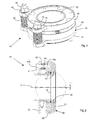
- the Figures 1 and 2 show a perspective view and a longitudinal section of a holder 10 for installation of optical analyzers, in particular optical gas analyzers, in a gas-carrying cavity.
- the holder 10 has a ball socket 20 and a spherical segment 30 mounted in the ball socket.
- the ball segment 30 can be firmly connected to the optical analyzer, while the ball socket 20 is fixedly connected to the wall of the gas-carrying cavity.
- the inclination of the gas sensor can thus be varied relative to the gas-carrying cavity, in particular in two axes.
- the ball socket 20 is designed such that it at least partially surrounds the ball segment 30 in the direction of the longitudinal axis A of the ball segment 30. Seen along the longitudinal axis A of the ball segment 30, the ball socket 20 lies on both sides of a largest diameter D of sections perpendicular to the longitudinal axis A of the ball segment 30 against the ball segment 30. The ball socket 20 thus fixes the ball segment 30 in the direction of the longitudinal axis A.
- the ball socket 20 has a first segment 21 and a second segment 22, between which the ball segment 30 is inserted.
- the ball segment 30 can be tilted in the ball socket 20, but after joining the two segments 21, 22 of the ball socket 20 are not pushed out of the ball socket 20.
- a cylindrical portion 32 is formed, whose longitudinal axis coincides with the longitudinal axis A of the ball segment 30.
- a fastening ring 34 is arranged at the ball segment 30 facing the free end of the cylindrical portion 32.
- the inclination of the ball segment 30 relative to the ball socket 20 is fixed by means of two threaded rods 40, which are arranged on the fastening ring 34 of the ball segment 30 and on the second segment 22 of the ball socket 20.
- the threaded rods 40 in this case have a first end 40a and a second end 40b, wherein the first end 40a of the threaded rod 40 is respectively firmly and non-rotatably connected to the second segment 22 of the ball socket 20.
- the second end 40 b of the threaded rods 40 is guided through a through opening 36 of the fastening ring 34.
- the relative position of the fastening ring 34 relative to the threaded rod 40 can be fixed by means of two nuts turned on both sides of the fastening ring 34 onto the threaded rod 40.
- a helical spring 42 is provided between the second segment 22 of the ball socket 20 and the mounting ring 34, while only on the side facing away from the ball socket 20 of the mounting ring 34 is a respective nut 44 is screwed onto the threaded rod 40.
- the nut 44 can be tightened on the threaded rod 40 to vary the relative position of the mounting ring 34 relative to the threaded rod 40 and thus the inclination of the ball segment 30 relative to the ball socket 20 and fix.
- an inclination of the ball segment 30 with respect to the ball socket 20 by ⁇ 2 ° about the longitudinal axis A is possible.
- a stepless change of inclination is possible in particular by using the coil spring 42.
- the ball segment in the ball socket By using the ball segment in the ball socket, a short design of the holder 10 is made possible, which withstands positioning of the ball segment 30 along the longitudinal axis A in both directions and high pressures of up to 20 bar and also easy to use and easy to clean , By introducing one or more seals 50 in the inner surface of the ball socket 20 between the ball socket 20 and the ball segment 30, a sufficient tightness can be ensured for toxic gases even at high pressures.
Landscapes
- Physics & Mathematics (AREA)
- General Physics & Mathematics (AREA)
- Health & Medical Sciences (AREA)
- Life Sciences & Earth Sciences (AREA)
- Chemical & Material Sciences (AREA)
- Analytical Chemistry (AREA)
- Biochemistry (AREA)
- General Health & Medical Sciences (AREA)
- Immunology (AREA)
- Pathology (AREA)
- Optics & Photonics (AREA)
- Optical Measuring Cells (AREA)
Abstract
Description
- Die Erfindung betrifft einen optischen Analysator mit einer Halterung zum Einbau in einen gasführenden Hohlraum.
- Bekannt sind optische Analysatoren, insbesondere optische Gasanalysatoren, welche in gasführende Hohlräume eingebaut werden. Die Gasanalysatoren werden dabei in einen Durchbruch in der Wand des gasführenden Hohlraums eingesetzt. Da in den gasführenden Hohlräumen oft Drücke bis zu 20 bar vorhanden sind, ist es erforderlich, dass die Halterungen für entsprechende Drücke ausgelegt sind. Weiterhin ist es erforderlich, dass die Gasanalysatoren eine Halterung aufweisen, über welche die Neigung der Gasanalysatoren in zwei Achsen relativ zu dem gasführenden Hohlraum eingestellt werden kann, da die Halterungen oft nicht mit der erforderlichen Genauigkeit in den Durchbruch des gasführenden Hohlraums eingesetzt, insbesondere eingeschweißt, werden können. Bekannt sind Halterungen, welche mit Hilfe eines Gummibands abgedichtet werden, welches über zwei relativ zueinander kippbare Flanschflächen gespannt wird. Alternativ ist es ebenfalls bekannt, einen O-Ring aus Gummi zwischen zwei Flansche zu legen und die Flanschschrauben entsprechend anzuziehen, bis der gewünschte Neigungswinkel erreicht ist. Derartige Abdichtungen halten jedoch hohen Druckdifferenzen nicht stand.
- Bekannt sind weiterhin Halterungen mit zwei Flanschen, zwischen denen ein Metallfaltenbalg eingesetzt ist, wobei die Neigung der zwei Flansche relativ zueinander mit Hilfe von Gewindestangen, Schraubenmuttern und Kontermuttern variiert werden kann. Eine derartige Halterung hat jedoch eine lange Bauform zur Folge. Zudem können sich in den Hinterschnitten des Falkenbalgs im Inneren Staub oder sonstige Verschmutzungen ansammeln. Weiterhin ist eine Reinigung des Falkenbalgs extrem aufwändig. Schließlich sind Halterungen bekannt, bei welchen ein Kugelsegment in einer einteiligen Kugelpfanne eingesetzt ist. Bei hohen Drücken besteht jedoch die Gefahr, dass das Kugelsegment aus der Kugelpfanne herausgedrückt wird.
- Es sind auch Vorrichtungen bekannt, bei denen ein druckdichtes Fenster vor der Justagevorrichtung verhindert, dass hoher Druck oder Verschmutzung aus dem gasführenden Messraum auf die Justageeinrichtung einwirkt. Ein solches Fenster ist aber nachteilig mit hohem Kosten- und Montageaufwand verbunden. Es kann leicht verschmutzen und beeinflusst nachteilig die Optik.
- Die Aufgabe der Erfindung besteht daher darin, einen optischen Analysator mit einer Halterung zum Einbau in einen gasführenden Hohlraum bereitzustellen, wobei die Halterung auch Drücken von bis zu 20 bar standhält, welche jedoch insgesamt einfacher aufgebaut ist und insbesondere einfach zu bedienen und einfach zu reinigen ist.
- Die Aufgabe wird erfindungsgemäß gelöst durch einen optischen Analysator mit einer Halterung zum Einbau in einen gasführenden Hohlraum mit den Merkmalen des Patentanspruchs 1.
- Vorteilhafte Ausgestaltungen und Weiterbildungen der Erfindung sind in den abhängigen Ansprüchen angegeben.
- Der erfindungsgemäße optische Analysator, welcher insbesondere ein optischer Gasanalysator ist, mit einer Halterung zum Einbau in einen gasführenden Hohlraum, wobei die Halterung eine Kugelpfanne und ein Kugelsegment mit einer Längsachse aufweist, zeichnet sich dadurch aus, dass die Kugelpfanne wenigstens ein erstes Segment und ein zweites Segment aufweist und derart ausgebildet ist, dass sie das Kugelsegment in Richtung der Längsachse zumindest teilweise umgreift. Unter einem teilweisen Umgreifen ist zu verstehen, dass die Innenfläche der Kugelpfanne beidseitig eines größten Durchmessers des Kugelsegments bei Schnitten senkrecht zur Längsachse des Kugelsegments anliegt. Das Kugelsegment wird somit bei einem teilweisen Umgreifen durch die Kugelpfanne in Richtung der Längsachse fixiert. Somit können insbesondere Kräfte in beide Richtungen entlang der Längsachse aufgenommen werden. Ein Herausdrücken des Kugelsegments aus der Kugelpfanne ist somit nicht mehr möglich. Die Halterung ist damit insbesondere für Drücke von bis zu 20 bar geeignet.
- Die Neigung der Kugelpfanne relativ zum Kugelsegment ist vorzugsweise mittels wenigstens zweier Gewindestangen, vorzugsweise mittels vier Gewindestangen, fixierbar, was eine einfache Konstruktion der Halterung ermöglicht.
- Vorzugsweise sind die Gewindestangen an einem Ende fest mit der Kugelpfanne verbunden und an ihrem anderen Ende mit Hilfe von Schraubenmuttern an dem Kugelsegment direkt oder indirekt fixierbar. Selbstverständlich ist es ebenfalls möglich, die Gewindestangen an einem Ende an dem Kugelsegment anzuordnen und ihr anderes Ende mit Hilfe von Schraubenmuttern an der Kugelpfanne zu fixieren.
- In einer Variante sind an jeder Gewindestange zwei Schraubenmuttern vorgesehen, nämlich eine Schraubenmutter und eine Kontermutter, mit Hilfe derer die Neigung zwischen der Kugelpfanne und dem Kugelsegment eingestellt werden kann. Nachteilig dabei ist jedoch, dass keine stufenlose Einstellung der Neigung möglich ist. Gemäß einer besonders bevorzugten Ausführungsform der Erfindung ist daher zwischen der Kugelpfanne und dem Kugelsegment ein Federelement angeordnet. Es ist somit möglich, lediglich jeweils eine Schraubenmutter pro Gewindestange vorzusehen und diese gegen die Federkraft anzuziehen, um die Neigung zwischen der Kugelpfanne und dem Kugelsegment stufenlos einstellen zu können.
- Gemäß einer besonders bevorzugten Ausführungsform der Erfindung ist um wenigstens eine der Gewindestangen zwischen der Kugelpfanne und dem Kugelsegment eine Schraubenfeder oder eine Tellerfeder angeordnet, wodurch auf besonders einfache und kostengünstige Art und Weise eine stufenlose Verstellung der Neigung zwischen der Kugelpfanne und dem Kugelsegment ermöglicht wird.
- Ein Ausführungsbeispiel der Erfindung wird anhand der nachfolgenden Figuren ausführlich erläutert. Es zeigt:
- Fig. 1
- eine perspektivische Ansicht des Ausführungsbeispiels einer erfindungsgemäßen Halterung und
- Fig. 2
- einen Längsschnitt durch die Halterung gemäß
Figur 1 . - Die
Figuren 1 und 2 zeigen eine perspektivische Ansicht und einen Längsschnitt einer Halterung 10 zum Einbau von optischen Analysatoren, insbesondere optischen Gasanalysatoren, in einen gasführenden Hohlraum. Die Halterung 10 weist eine Kugelpfanne 20 und ein in der Kugelpfanne gelagertes Kugelsegment 30 auf. Das Kugelsegment 30 kann dabei mit dem optischen Analysator fest verbunden sein, während die Kugelpfanne 20 mit der Wandung des gasführenden Hohlraums fest verbunden ist. Durch Verkippen des Kugelsegments 30 in der Kugelpfanne 20 kann somit die Neigung des Gassensors relativ zu dem gasführenden Hohlraum variiert werden, insbesondere in zwei Achsen. - Die Kugelpfanne 20 ist derart ausgebildet, dass sie das Kugelsegment 30 in Richtung der Längsachse A des Kugelsegments 30 zumindest teilweise umgreift. Entlang der Längsachse A des Kugelsegments 30 gesehen, liegt dazu die Kugelpfanne 20 beidseitig eines größten Durchmessers D von Schnitten senkrecht zur Längsachse A des Kugelsegments 30 an dem Kugelsegment 30 an. Die Kugelpfanne 20 fixiert somit das Kugelsegment 30 in Richtung der Längsachse A.
- Um das Kugelsegment 30 in die Kugelpfanne 20 einbringen zu können, weist die Kugelpfanne 20 ein erstes Segment 21 und ein zweites Segment 22 auf, zwischen welchen das Kugelsegment 30 eingesetzt wird. Das Kugelsegment 30 kann in der Kugelpfanne 20 verkippt werden, jedoch nach Zusammenfügen der beiden Segmente 21, 22 der Kugelpfanne 20 nicht aus der Kugelpfanne 20 herausgedrückt werden.
- An dem Kugelsegment 30 ist ein zylindrischer Abschnitt 32 angeformt, dessen Längsachse mit der Längsachse A des Kugelsegments 30 zusammenfällt. An dem dem Kugelsegment 30 zugewandten freien Ende des zylindrischen Abschnitts 32 ist ein Befestigungsring 34 angeordnet.
- Die Neigung des Kugelsegments 30 relativ zur Kugelpfanne 20 wird mittels zweier Gewindestangen 40 fixiert, welche an dem Befestigungsring 34 des Kugelsegments 30 und an dem zweiten Segment 22 der Kugelpfanne 20 angeordnet sind. Die Gewindestangen 40 weisen dabei ein erstes Ende 40a und ein zweites Ende 40b auf, wobei das erste Ende 40a der Gewindestange 40 jeweils fest und unverdrehbar mit dem zweiten Segment 22 der Kugelpfanne 20 verbunden ist. Das zweite Ende 40b der Gewindestangen 40 ist durch eine Durchgangsöffnung 36 des Befestigungsrings 34 geführt. Die relative Lage des Befestigungsrings 34 gegenüber der Gewindestange 40 kann mittels zweier beidseitig des Befestigungsrings 34 auf die Gewindestange 40 gedrehten Muttern fixiert werden. In dem vorliegenden Ausführungsbeispiel ist jedoch zwischen dem zweiten Segment 22 der Kugelpfanne 20 und dem Befestigungsring 34 eine Schraubenfeder 42 vorgesehen, während lediglich auf der dem der Kugelpfanne 20 abgewandten Seite des Befestigungsrings 34 jeweils eine Schraubenmutter 44 auf die Gewindestange 40 aufgedreht ist. Gegen die Federkraft der Schraubenfeder 42 kann die Schraubenmutter 44 auf der Gewindestange 40 angezogen werden, um die relative Lage des Befestigungsrings 34 gegenüber der Gewindestange 40 und somit die Neigung des Kugelsegments 30 gegenüber der Kugelpfanne 20 zu variieren und zu fixieren. Insbesondere ist eine Neigung des Kugelsegments 30 gegenüber der Kugelpfanne 20 um ±2° um die Längsachse A möglich. Dabei ist insbesondere durch Verwendung der Schraubenfeder 42 eine stufenlose Änderung der Neigung möglich.
- Durch die Verwendung des Kugelsegments in der Kugelpfanne wird eine kurze Bauform der Halterung 10 ermöglicht, die aufgrund der Fixierung des Kugelsegments 30 entlang der Längsachse A in beide Richtungen auch hohen Drücken von bis zu 20 bar standhält und zudem einfach zu bedienen und einfach zu reinigen ist. Durch Einbringen von einer oder mehrerer Dichtungen 50 in die Innenfläche der Kugelpfanne 20 zwischen der Kugelpfanne 20 und dem Kugelsegment 30 kann auch bei hohen Drücken eine ausreichende Dichtigkeit auch für giftige Gase gewährleistet werden.
-
- 10
- Halterung
- 20
- Kugelpfanne
- 21
- erstes Segment
- 22
- zweites Segment
- 30
- Kugelsegment
- 32
- zylindrischer Abschnitt
- 34
- Befestigungsring
- 36
- Durchgangsöffnung
- 40
- Gewindestange
- 40a
- erstes Ende
- 40b
- zweites Ende
- 42
- Schraubenfeder
- 44
- Schraubenmutter
- 50
- Dichtung
- A
- Längsachse
- D
- Durchmesser
Claims (5)
- Optischer Analysator, insbesondere optischer Gasanalysator, mit einer Halterung (10) zum Einbau in einen gasführenden Hohlraum, wobei die Halterung (10) eine Kugelpfanne (20) und ein Kugelsegment (30) mit einer Längsachse (A) aufweist, dadurch gekennzeichnet, dass die Kugelpfanne (20) wenigstens ein erstes Segment (21) und ein zweites Segment (22) aufweist und derart ausgebildet ist, dass sie das Kugelsegment (30) in Richtung der Längsachse (A) zumindest teilweise umgreift.
- Optischer Analysator nach Anspruch 1,
dadurch gekennzeichnet, dass die Kugelpfanne (20) relativ zum Kugelsegment (30) mittels wenigstens zweier Gewindestangen (40), vorzugsweise mittels vier Gewindestangen (40), fixierbar ist. - Optischer Analysator nach Anspruch 2,
dadurch gekennzeichnet, dass die Gewindestangen (40) an einem Ende (40a) fest mit der Kugelpfanne (20) verbunden sind und an ihrem anderen Ende (40b) mit Hilfe von Schraubenmuttern (44) an dem Kugelsegment (30) direkt oder indirekt fixierbar sind. - Optischer Analysator nach Anspruch 2 oder 3,
dadurch gekennzeichnet, dass zwischen der Kugelpfanne (20) und dem Kugelsegment (30) ein Federelement (12) angeordnet ist. - Optischer Analysator nach einem der Ansprüche 2 bis 4,
dadurch gekennzeichnet, dass um wenigstens eine der Gewindestangen (40) zwischen der Kugelpfanne (20) und dem Kugelsegment (30) eine Schraubenfeder (42) oder eine Tellerfeder angeordnet ist.
Priority Applications (3)
| Application Number | Priority Date | Filing Date | Title |
|---|---|---|---|
| EP10196301A EP2479555B1 (de) | 2010-12-21 | 2010-12-21 | Optischer Analysator mit einer Halterung zum Einbau in einen gasführenden Hohlraum |
| US13/326,450 US8982343B2 (en) | 2010-12-21 | 2011-12-15 | Optical analyzer having a holder for installation in a gas-carrying hollow space |
| KR1020110139440A KR101351489B1 (ko) | 2010-12-21 | 2011-12-21 | 가스를 유도하는 중공 공간 안에 설치하기 위한 홀더를 구비한 광학 분석기 |
Applications Claiming Priority (1)
| Application Number | Priority Date | Filing Date | Title |
|---|---|---|---|
| EP10196301A EP2479555B1 (de) | 2010-12-21 | 2010-12-21 | Optischer Analysator mit einer Halterung zum Einbau in einen gasführenden Hohlraum |
Publications (2)
| Publication Number | Publication Date |
|---|---|
| EP2479555A1 true EP2479555A1 (de) | 2012-07-25 |
| EP2479555B1 EP2479555B1 (de) | 2013-03-13 |
Family
ID=43837977
Family Applications (1)
| Application Number | Title | Priority Date | Filing Date |
|---|---|---|---|
| EP10196301A Active EP2479555B1 (de) | 2010-12-21 | 2010-12-21 | Optischer Analysator mit einer Halterung zum Einbau in einen gasführenden Hohlraum |
Country Status (3)
| Country | Link |
|---|---|
| US (1) | US8982343B2 (de) |
| EP (1) | EP2479555B1 (de) |
| KR (1) | KR101351489B1 (de) |
Cited By (1)
| Publication number | Priority date | Publication date | Assignee | Title |
|---|---|---|---|---|
| US9927296B2 (en) | 2013-06-20 | 2018-03-27 | Rosemount Analytical Inc. | Alignment system for laser spectroscopy |
Families Citing this family (2)
| Publication number | Priority date | Publication date | Assignee | Title |
|---|---|---|---|---|
| CN104199164B (zh) * | 2014-08-29 | 2016-05-11 | 成都科信达实业有限公司 | 光学镜片垂直驱动器 |
| US20180052101A1 (en) * | 2016-08-22 | 2018-02-22 | Yuguang Cai | Apparatus and Method for Measuring Components in Fluidic Samples Sealed in a Bag |
Citations (2)
| Publication number | Priority date | Publication date | Assignee | Title |
|---|---|---|---|---|
| US4622465A (en) * | 1983-04-28 | 1986-11-11 | U.S. Philips Corporation | Arrangement for determining the presence of specific substances in a liquid |
| US20040232340A1 (en) * | 2001-09-20 | 2004-11-25 | Benson Ian Beethom | Optical window for monitoring samples |
Family Cites Families (6)
| Publication number | Priority date | Publication date | Assignee | Title |
|---|---|---|---|---|
| US3897139A (en) * | 1974-04-15 | 1975-07-29 | United Aircraft Corp | Adjustable mounting apparatus |
| US4515336A (en) * | 1983-04-14 | 1985-05-07 | Opcon, Inc. | Ball and socket mount for optical sensing system source and/or detector devices |
| US5596404A (en) * | 1994-12-30 | 1997-01-21 | Albion Instruments, Inc. | Raman gas analysis system with flexible web and differential thread for precision optical alignment |
| JP4845599B2 (ja) | 2006-06-05 | 2011-12-28 | トヨタ自動車株式会社 | ガス分析装置及びガス分析装置におけるセンサユニット |
| JP2009270917A (ja) | 2008-05-07 | 2009-11-19 | Nohken:Kk | レーザ式ガス分析計の取付構造 |
| US8564768B2 (en) * | 2009-04-17 | 2013-10-22 | Schlumberger Technology Corporation | High pressure and high temperature optical spectroscopy cell using spherical surfaced lenses in direct contact with a fluid pathway |
-
2010
- 2010-12-21 EP EP10196301A patent/EP2479555B1/de active Active
-
2011
- 2011-12-15 US US13/326,450 patent/US8982343B2/en active Active
- 2011-12-21 KR KR1020110139440A patent/KR101351489B1/ko not_active Expired - Fee Related
Patent Citations (2)
| Publication number | Priority date | Publication date | Assignee | Title |
|---|---|---|---|---|
| US4622465A (en) * | 1983-04-28 | 1986-11-11 | U.S. Philips Corporation | Arrangement for determining the presence of specific substances in a liquid |
| US20040232340A1 (en) * | 2001-09-20 | 2004-11-25 | Benson Ian Beethom | Optical window for monitoring samples |
Cited By (1)
| Publication number | Priority date | Publication date | Assignee | Title |
|---|---|---|---|---|
| US9927296B2 (en) | 2013-06-20 | 2018-03-27 | Rosemount Analytical Inc. | Alignment system for laser spectroscopy |
Also Published As
| Publication number | Publication date |
|---|---|
| EP2479555B1 (de) | 2013-03-13 |
| KR20120070535A (ko) | 2012-06-29 |
| KR101351489B1 (ko) | 2014-01-14 |
| US20120154799A1 (en) | 2012-06-21 |
| US8982343B2 (en) | 2015-03-17 |
Similar Documents
| Publication | Publication Date | Title |
|---|---|---|
| EP2132847A1 (de) | Kabelverschraubung mit einer gegenhülse oder überwurfmutter | |
| DE4447456C2 (de) | Montageschiene | |
| DE102015108302A1 (de) | Befestigungselement | |
| DE102005007766B3 (de) | Vorrichtung zum Zentrieren von miteinander zu verschweißenden Rohrstößen | |
| EP2479555B1 (de) | Optischer Analysator mit einer Halterung zum Einbau in einen gasführenden Hohlraum | |
| DE102023128614A1 (de) | Reifendrucksensor mit verriegelbarer Gasdüse | |
| EP1029638A1 (de) | Roboterteil mit einem Schlauchhalter | |
| EP0787909B1 (de) | Klemmvorrichtung für teleskopisch zusammengesetzte Profilrohre | |
| DE102017123765A1 (de) | Adapter zum Anschluss einer Ventil- oder Spülarmatur an eine Rohrleitung und System mit einem solchen Adapter und einem Vorwandgestellelement | |
| DE102020203827A1 (de) | Lenksäule für ein Kraftfahrzeug | |
| EP1191269A2 (de) | Toleranzausgleichende lösbare und nicht lösbare Rohrverbindungen | |
| DE202005012296U1 (de) | Rohrleitungspassstück | |
| DE4101849A1 (de) | Flanschverbindung | |
| WO2010040334A1 (de) | Verschlusskupplung | |
| DE102010031995A1 (de) | Kugelkopfverbindung | |
| WO2023174847A1 (de) | Profilschelle | |
| WO2023285190A1 (de) | FELDGERÄT MIT EINEM SENSOR ZUR ERFASSUNG EINER PHYSIKALISCHEN MESSGRÖßE UND KLEMMELEMENT ZUR BEFESTIGUNG EINES GEHÄUSES EINES FELDGERÄTS AN EINEM SENSORHALS | |
| EP0620397B1 (de) | Tragvorrichtung | |
| EP2551533A1 (de) | Sensor | |
| DE202005016936U1 (de) | Optoelektronische Sensoreinrichtung | |
| DE8602266U1 (de) | Gesicherte Schraubverbindung | |
| AT509653B1 (de) | Vorrichtung zur befestigung einer armatur | |
| EP3850175B1 (de) | Einrichtung zur justierung eines türantriebs | |
| DE19834735A1 (de) | Vorrichtung zum Abkoppeln von Torsions- und Biegeschwingungen in Rohrleitungen | |
| DE202005010983U1 (de) | Halterung für Sonnenschutzanlagen |
Legal Events
| Date | Code | Title | Description |
|---|---|---|---|
| PUAI | Public reference made under article 153(3) epc to a published international application that has entered the european phase |
Free format text: ORIGINAL CODE: 0009012 |
|
| 17P | Request for examination filed |
Effective date: 20110609 |
|
| AK | Designated contracting states |
Kind code of ref document: A1 Designated state(s): AL AT BE BG CH CY CZ DE DK EE ES FI FR GB GR HR HU IE IS IT LI LT LU LV MC MK MT NL NO PL PT RO RS SE SI SK SM TR |
|
| AX | Request for extension of the european patent |
Extension state: BA ME |
|
| GRAP | Despatch of communication of intention to grant a patent |
Free format text: ORIGINAL CODE: EPIDOSNIGR1 |
|
| GRAS | Grant fee paid |
Free format text: ORIGINAL CODE: EPIDOSNIGR3 |
|
| GRAA | (expected) grant |
Free format text: ORIGINAL CODE: 0009210 |
|
| AK | Designated contracting states |
Kind code of ref document: B1 Designated state(s): AL AT BE BG CH CY CZ DE DK EE ES FI FR GB GR HR HU IE IS IT LI LT LU LV MC MK MT NL NO PL PT RO RS SE SI SK SM TR |
|
| REG | Reference to a national code |
Ref country code: GB Ref legal event code: FG4D Free format text: NOT ENGLISH |
|
| REG | Reference to a national code |
Ref country code: CH Ref legal event code: EP Ref country code: AT Ref legal event code: REF Ref document number: 601083 Country of ref document: AT Kind code of ref document: T Effective date: 20130315 |
|
| REG | Reference to a national code |
Ref country code: IE Ref legal event code: FG4D Free format text: LANGUAGE OF EP DOCUMENT: GERMAN |
|
| REG | Reference to a national code |
Ref country code: DE Ref legal event code: R096 Ref document number: 502010002533 Country of ref document: DE Effective date: 20130508 |
|
| PG25 | Lapsed in a contracting state [announced via postgrant information from national office to epo] |
Ref country code: BG Free format text: LAPSE BECAUSE OF FAILURE TO SUBMIT A TRANSLATION OF THE DESCRIPTION OR TO PAY THE FEE WITHIN THE PRESCRIBED TIME-LIMIT Effective date: 20130613 Ref country code: LT Free format text: LAPSE BECAUSE OF FAILURE TO SUBMIT A TRANSLATION OF THE DESCRIPTION OR TO PAY THE FEE WITHIN THE PRESCRIBED TIME-LIMIT Effective date: 20130313 Ref country code: SE Free format text: LAPSE BECAUSE OF FAILURE TO SUBMIT A TRANSLATION OF THE DESCRIPTION OR TO PAY THE FEE WITHIN THE PRESCRIBED TIME-LIMIT Effective date: 20130313 Ref country code: NO Free format text: LAPSE BECAUSE OF FAILURE TO SUBMIT A TRANSLATION OF THE DESCRIPTION OR TO PAY THE FEE WITHIN THE PRESCRIBED TIME-LIMIT Effective date: 20130613 Ref country code: ES Free format text: LAPSE BECAUSE OF FAILURE TO SUBMIT A TRANSLATION OF THE DESCRIPTION OR TO PAY THE FEE WITHIN THE PRESCRIBED TIME-LIMIT Effective date: 20130624 |
|
| REG | Reference to a national code |
Ref country code: NL Ref legal event code: VDEP Effective date: 20130313 |
|
| REG | Reference to a national code |
Ref country code: LT Ref legal event code: MG4D |
|
| PG25 | Lapsed in a contracting state [announced via postgrant information from national office to epo] |
Ref country code: FI Free format text: LAPSE BECAUSE OF FAILURE TO SUBMIT A TRANSLATION OF THE DESCRIPTION OR TO PAY THE FEE WITHIN THE PRESCRIBED TIME-LIMIT Effective date: 20130313 Ref country code: SI Free format text: LAPSE BECAUSE OF FAILURE TO SUBMIT A TRANSLATION OF THE DESCRIPTION OR TO PAY THE FEE WITHIN THE PRESCRIBED TIME-LIMIT Effective date: 20130313 Ref country code: LV Free format text: LAPSE BECAUSE OF FAILURE TO SUBMIT A TRANSLATION OF THE DESCRIPTION OR TO PAY THE FEE WITHIN THE PRESCRIBED TIME-LIMIT Effective date: 20130313 Ref country code: GR Free format text: LAPSE BECAUSE OF FAILURE TO SUBMIT A TRANSLATION OF THE DESCRIPTION OR TO PAY THE FEE WITHIN THE PRESCRIBED TIME-LIMIT Effective date: 20130614 |
|
| PG25 | Lapsed in a contracting state [announced via postgrant information from national office to epo] |
Ref country code: HR Free format text: LAPSE BECAUSE OF FAILURE TO SUBMIT A TRANSLATION OF THE DESCRIPTION OR TO PAY THE FEE WITHIN THE PRESCRIBED TIME-LIMIT Effective date: 20130313 Ref country code: RS Free format text: LAPSE BECAUSE OF FAILURE TO SUBMIT A TRANSLATION OF THE DESCRIPTION OR TO PAY THE FEE WITHIN THE PRESCRIBED TIME-LIMIT Effective date: 20130313 |
|
| PG25 | Lapsed in a contracting state [announced via postgrant information from national office to epo] |
Ref country code: CZ Free format text: LAPSE BECAUSE OF FAILURE TO SUBMIT A TRANSLATION OF THE DESCRIPTION OR TO PAY THE FEE WITHIN THE PRESCRIBED TIME-LIMIT Effective date: 20130313 Ref country code: SK Free format text: LAPSE BECAUSE OF FAILURE TO SUBMIT A TRANSLATION OF THE DESCRIPTION OR TO PAY THE FEE WITHIN THE PRESCRIBED TIME-LIMIT Effective date: 20130313 Ref country code: RO Free format text: LAPSE BECAUSE OF FAILURE TO SUBMIT A TRANSLATION OF THE DESCRIPTION OR TO PAY THE FEE WITHIN THE PRESCRIBED TIME-LIMIT Effective date: 20130313 Ref country code: PT Free format text: LAPSE BECAUSE OF FAILURE TO SUBMIT A TRANSLATION OF THE DESCRIPTION OR TO PAY THE FEE WITHIN THE PRESCRIBED TIME-LIMIT Effective date: 20130715 Ref country code: EE Free format text: LAPSE BECAUSE OF FAILURE TO SUBMIT A TRANSLATION OF THE DESCRIPTION OR TO PAY THE FEE WITHIN THE PRESCRIBED TIME-LIMIT Effective date: 20130313 Ref country code: NL Free format text: LAPSE BECAUSE OF FAILURE TO SUBMIT A TRANSLATION OF THE DESCRIPTION OR TO PAY THE FEE WITHIN THE PRESCRIBED TIME-LIMIT Effective date: 20130313 Ref country code: IS Free format text: LAPSE BECAUSE OF FAILURE TO SUBMIT A TRANSLATION OF THE DESCRIPTION OR TO PAY THE FEE WITHIN THE PRESCRIBED TIME-LIMIT Effective date: 20130713 |
|
| PG25 | Lapsed in a contracting state [announced via postgrant information from national office to epo] |
Ref country code: PL Free format text: LAPSE BECAUSE OF FAILURE TO SUBMIT A TRANSLATION OF THE DESCRIPTION OR TO PAY THE FEE WITHIN THE PRESCRIBED TIME-LIMIT Effective date: 20130313 |
|
| PLBE | No opposition filed within time limit |
Free format text: ORIGINAL CODE: 0009261 |
|
| STAA | Information on the status of an ep patent application or granted ep patent |
Free format text: STATUS: NO OPPOSITION FILED WITHIN TIME LIMIT |
|
| PG25 | Lapsed in a contracting state [announced via postgrant information from national office to epo] |
Ref country code: DK Free format text: LAPSE BECAUSE OF FAILURE TO SUBMIT A TRANSLATION OF THE DESCRIPTION OR TO PAY THE FEE WITHIN THE PRESCRIBED TIME-LIMIT Effective date: 20130313 |
|
| 26N | No opposition filed |
Effective date: 20131216 |
|
| PG25 | Lapsed in a contracting state [announced via postgrant information from national office to epo] |
Ref country code: IT Free format text: LAPSE BECAUSE OF FAILURE TO SUBMIT A TRANSLATION OF THE DESCRIPTION OR TO PAY THE FEE WITHIN THE PRESCRIBED TIME-LIMIT Effective date: 20130313 |
|
| REG | Reference to a national code |
Ref country code: DE Ref legal event code: R097 Ref document number: 502010002533 Country of ref document: DE Effective date: 20131216 |
|
| BERE | Be: lapsed |
Owner name: SICK A.G. Effective date: 20131231 |
|
| PG25 | Lapsed in a contracting state [announced via postgrant information from national office to epo] |
Ref country code: LU Free format text: LAPSE BECAUSE OF FAILURE TO SUBMIT A TRANSLATION OF THE DESCRIPTION OR TO PAY THE FEE WITHIN THE PRESCRIBED TIME-LIMIT Effective date: 20131221 |
|
| REG | Reference to a national code |
Ref country code: IE Ref legal event code: MM4A |
|
| PG25 | Lapsed in a contracting state [announced via postgrant information from national office to epo] |
Ref country code: IE Free format text: LAPSE BECAUSE OF NON-PAYMENT OF DUE FEES Effective date: 20131221 Ref country code: BE Free format text: LAPSE BECAUSE OF NON-PAYMENT OF DUE FEES Effective date: 20131231 |
|
| PG25 | Lapsed in a contracting state [announced via postgrant information from national office to epo] |
Ref country code: MC Free format text: LAPSE BECAUSE OF FAILURE TO SUBMIT A TRANSLATION OF THE DESCRIPTION OR TO PAY THE FEE WITHIN THE PRESCRIBED TIME-LIMIT Effective date: 20130313 |
|
| PG25 | Lapsed in a contracting state [announced via postgrant information from national office to epo] |
Ref country code: SM Free format text: LAPSE BECAUSE OF FAILURE TO SUBMIT A TRANSLATION OF THE DESCRIPTION OR TO PAY THE FEE WITHIN THE PRESCRIBED TIME-LIMIT Effective date: 20130313 |
|
| PG25 | Lapsed in a contracting state [announced via postgrant information from national office to epo] |
Ref country code: CY Free format text: LAPSE BECAUSE OF FAILURE TO SUBMIT A TRANSLATION OF THE DESCRIPTION OR TO PAY THE FEE WITHIN THE PRESCRIBED TIME-LIMIT Effective date: 20130313 |
|
| PG25 | Lapsed in a contracting state [announced via postgrant information from national office to epo] |
Ref country code: MK Free format text: LAPSE BECAUSE OF FAILURE TO SUBMIT A TRANSLATION OF THE DESCRIPTION OR TO PAY THE FEE WITHIN THE PRESCRIBED TIME-LIMIT Effective date: 20130313 Ref country code: HU Free format text: LAPSE BECAUSE OF FAILURE TO SUBMIT A TRANSLATION OF THE DESCRIPTION OR TO PAY THE FEE WITHIN THE PRESCRIBED TIME-LIMIT; INVALID AB INITIO Effective date: 20101221 |
|
| REG | Reference to a national code |
Ref country code: CH Ref legal event code: PL |
|
| PG25 | Lapsed in a contracting state [announced via postgrant information from national office to epo] |
Ref country code: MT Free format text: LAPSE BECAUSE OF FAILURE TO SUBMIT A TRANSLATION OF THE DESCRIPTION OR TO PAY THE FEE WITHIN THE PRESCRIBED TIME-LIMIT Effective date: 20130313 |
|
| PGFP | Annual fee paid to national office [announced via postgrant information from national office to epo] |
Ref country code: IT Payment date: 20131231 Year of fee payment: 4 |
|
| PGRI | Patent reinstated in contracting state [announced from national office to epo] |
Ref country code: IT Effective date: 20150604 |
|
| PG25 | Lapsed in a contracting state [announced via postgrant information from national office to epo] |
Ref country code: CH Free format text: LAPSE BECAUSE OF NON-PAYMENT OF DUE FEES Effective date: 20141231 Ref country code: LI Free format text: LAPSE BECAUSE OF NON-PAYMENT OF DUE FEES Effective date: 20141231 |
|
| REG | Reference to a national code |
Ref country code: FR Ref legal event code: PLFP Year of fee payment: 6 |
|
| PG25 | Lapsed in a contracting state [announced via postgrant information from national office to epo] |
Ref country code: IT Free format text: LAPSE BECAUSE OF FAILURE TO SUBMIT A TRANSLATION OF THE DESCRIPTION OR TO PAY THE FEE WITHIN THE PRESCRIBED TIME-LIMIT Effective date: 20141221 |
|
| PGRI | Patent reinstated in contracting state [announced from national office to epo] |
Ref country code: IT Effective date: 20150604 |
|
| PG25 | Lapsed in a contracting state [announced via postgrant information from national office to epo] |
Ref country code: TR Free format text: LAPSE BECAUSE OF FAILURE TO SUBMIT A TRANSLATION OF THE DESCRIPTION OR TO PAY THE FEE WITHIN THE PRESCRIBED TIME-LIMIT Effective date: 20130313 |
|
| REG | Reference to a national code |
Ref country code: FR Ref legal event code: PLFP Year of fee payment: 7 |
|
| PGFP | Annual fee paid to national office [announced via postgrant information from national office to epo] |
Ref country code: GB Payment date: 20161222 Year of fee payment: 7 |
|
| REG | Reference to a national code |
Ref country code: AT Ref legal event code: MM01 Ref document number: 601083 Country of ref document: AT Kind code of ref document: T Effective date: 20151221 |
|
| PGFP | Annual fee paid to national office [announced via postgrant information from national office to epo] |
Ref country code: FR Payment date: 20161221 Year of fee payment: 7 |
|
| PG25 | Lapsed in a contracting state [announced via postgrant information from national office to epo] |
Ref country code: AT Free format text: LAPSE BECAUSE OF NON-PAYMENT OF DUE FEES Effective date: 20151221 |
|
| GBPC | Gb: european patent ceased through non-payment of renewal fee |
Effective date: 20171221 |
|
| REG | Reference to a national code |
Ref country code: FR Ref legal event code: ST Effective date: 20180831 |
|
| PG25 | Lapsed in a contracting state [announced via postgrant information from national office to epo] |
Ref country code: AL Free format text: LAPSE BECAUSE OF FAILURE TO SUBMIT A TRANSLATION OF THE DESCRIPTION OR TO PAY THE FEE WITHIN THE PRESCRIBED TIME-LIMIT Effective date: 20130313 Ref country code: FR Free format text: LAPSE BECAUSE OF NON-PAYMENT OF DUE FEES Effective date: 20180102 |
|
| PG25 | Lapsed in a contracting state [announced via postgrant information from national office to epo] |
Ref country code: GB Free format text: LAPSE BECAUSE OF NON-PAYMENT OF DUE FEES Effective date: 20171221 |
|
| PGFP | Annual fee paid to national office [announced via postgrant information from national office to epo] |
Ref country code: DE Payment date: 20211220 Year of fee payment: 12 |
|
| REG | Reference to a national code |
Ref country code: DE Ref legal event code: R119 Ref document number: 502010002533 Country of ref document: DE |
|
| PG25 | Lapsed in a contracting state [announced via postgrant information from national office to epo] |
Ref country code: DE Free format text: LAPSE BECAUSE OF NON-PAYMENT OF DUE FEES Effective date: 20230701 |