EP2479414A2 - Verstellbare Fandüse mit Bypass-Strom - Google Patents
Verstellbare Fandüse mit Bypass-Strom Download PDFInfo
- Publication number
- EP2479414A2 EP2479414A2 EP12002710A EP12002710A EP2479414A2 EP 2479414 A2 EP2479414 A2 EP 2479414A2 EP 12002710 A EP12002710 A EP 12002710A EP 12002710 A EP12002710 A EP 12002710A EP 2479414 A2 EP2479414 A2 EP 2479414A2
- Authority
- EP
- European Patent Office
- Prior art keywords
- fan nozzle
- nozzle sleeve
- nacelle
- ring
- sleeve
- Prior art date
- Legal status (The legal status is an assumption and is not a legal conclusion. Google has not performed a legal analysis and makes no representation as to the accuracy of the status listed.)
- Granted
Links
- 238000011144 upstream manufacturing Methods 0.000 claims abstract description 34
- 230000033001 locomotion Effects 0.000 claims description 14
- 230000007246 mechanism Effects 0.000 claims description 9
- 238000013519 translation Methods 0.000 abstract description 21
- 239000000446 fuel Substances 0.000 description 10
- 230000002457 bidirectional effect Effects 0.000 description 8
- 239000003381 stabilizer Substances 0.000 description 8
- 230000005540 biological transmission Effects 0.000 description 7
- 230000008878 coupling Effects 0.000 description 7
- 238000010168 coupling process Methods 0.000 description 7
- 238000005859 coupling reaction Methods 0.000 description 7
- 230000000712 assembly Effects 0.000 description 5
- 238000000429 assembly Methods 0.000 description 5
- 230000000694 effects Effects 0.000 description 5
- 239000007789 gas Substances 0.000 description 5
- 238000002485 combustion reaction Methods 0.000 description 4
- 239000000203 mixture Substances 0.000 description 4
- 241000499489 Castor canadensis Species 0.000 description 3
- 235000011779 Menyanthes trifoliata Nutrition 0.000 description 3
- 230000008901 benefit Effects 0.000 description 2
- 210000003746 feather Anatomy 0.000 description 2
- 230000007257 malfunction Effects 0.000 description 2
- 230000009467 reduction Effects 0.000 description 2
- 238000007792 addition Methods 0.000 description 1
- 230000002411 adverse Effects 0.000 description 1
- 230000000740 bleeding effect Effects 0.000 description 1
- 238000004590 computer program Methods 0.000 description 1
- 238000013461 design Methods 0.000 description 1
- JXSJBGJIGXNWCI-UHFFFAOYSA-N diethyl 2-[(dimethoxyphosphorothioyl)thio]succinate Chemical compound CCOC(=O)CC(SP(=S)(OC)OC)C(=O)OCC JXSJBGJIGXNWCI-UHFFFAOYSA-N 0.000 description 1
- 230000005611 electricity Effects 0.000 description 1
- 238000000034 method Methods 0.000 description 1
- 238000012986 modification Methods 0.000 description 1
- 230000004048 modification Effects 0.000 description 1
- 238000005457 optimization Methods 0.000 description 1
- 238000012552 review Methods 0.000 description 1
- 238000000926 separation method Methods 0.000 description 1
- 230000006641 stabilisation Effects 0.000 description 1
- 238000011105 stabilization Methods 0.000 description 1
- 238000012360 testing method Methods 0.000 description 1
Images


Classifications
-
- F—MECHANICAL ENGINEERING; LIGHTING; HEATING; WEAPONS; BLASTING
- F02—COMBUSTION ENGINES; HOT-GAS OR COMBUSTION-PRODUCT ENGINE PLANTS
- F02K—JET-PROPULSION PLANTS
- F02K1/00—Plants characterised by the form or arrangement of the jet pipe or nozzle; Jet pipes or nozzles peculiar thereto
- F02K1/54—Nozzles having means for reversing jet thrust
- F02K1/76—Control or regulation of thrust reversers
- F02K1/763—Control or regulation of thrust reversers with actuating systems or actuating devices; Arrangement of actuators for thrust reversers
-
- F—MECHANICAL ENGINEERING; LIGHTING; HEATING; WEAPONS; BLASTING
- F02—COMBUSTION ENGINES; HOT-GAS OR COMBUSTION-PRODUCT ENGINE PLANTS
- F02K—JET-PROPULSION PLANTS
- F02K1/00—Plants characterised by the form or arrangement of the jet pipe or nozzle; Jet pipes or nozzles peculiar thereto
- F02K1/06—Varying effective area of jet pipe or nozzle
- F02K1/09—Varying effective area of jet pipe or nozzle by axially moving an external member, e.g. a shroud
-
- F—MECHANICAL ENGINEERING; LIGHTING; HEATING; WEAPONS; BLASTING
- F02—COMBUSTION ENGINES; HOT-GAS OR COMBUSTION-PRODUCT ENGINE PLANTS
- F02K—JET-PROPULSION PLANTS
- F02K1/00—Plants characterised by the form or arrangement of the jet pipe or nozzle; Jet pipes or nozzles peculiar thereto
- F02K1/28—Plants characterised by the form or arrangement of the jet pipe or nozzle; Jet pipes or nozzles peculiar thereto using fluid jets to influence the jet flow
- F02K1/30—Plants characterised by the form or arrangement of the jet pipe or nozzle; Jet pipes or nozzles peculiar thereto using fluid jets to influence the jet flow for varying effective area of jet pipe or nozzle
-
- F—MECHANICAL ENGINEERING; LIGHTING; HEATING; WEAPONS; BLASTING
- F02—COMBUSTION ENGINES; HOT-GAS OR COMBUSTION-PRODUCT ENGINE PLANTS
- F02K—JET-PROPULSION PLANTS
- F02K1/00—Plants characterised by the form or arrangement of the jet pipe or nozzle; Jet pipes or nozzles peculiar thereto
- F02K1/54—Nozzles having means for reversing jet thrust
- F02K1/64—Reversing fan flow
- F02K1/70—Reversing fan flow using thrust reverser flaps or doors mounted on the fan housing
- F02K1/72—Reversing fan flow using thrust reverser flaps or doors mounted on the fan housing the aft end of the fan housing being movable to uncover openings in the fan housing for the reversed flow
-
- F—MECHANICAL ENGINEERING; LIGHTING; HEATING; WEAPONS; BLASTING
- F02—COMBUSTION ENGINES; HOT-GAS OR COMBUSTION-PRODUCT ENGINE PLANTS
- F02K—JET-PROPULSION PLANTS
- F02K3/00—Plants including a gas turbine driving a compressor or a ducted fan
- F02K3/02—Plants including a gas turbine driving a compressor or a ducted fan in which part of the working fluid by-passes the turbine and combustion chamber
- F02K3/04—Plants including a gas turbine driving a compressor or a ducted fan in which part of the working fluid by-passes the turbine and combustion chamber the plant including ducted fans, i.e. fans with high volume, low pressure outputs, for augmenting the jet thrust, e.g. of double-flow type
- F02K3/06—Plants including a gas turbine driving a compressor or a ducted fan in which part of the working fluid by-passes the turbine and combustion chamber the plant including ducted fans, i.e. fans with high volume, low pressure outputs, for augmenting the jet thrust, e.g. of double-flow type with front fan
-
- F—MECHANICAL ENGINEERING; LIGHTING; HEATING; WEAPONS; BLASTING
- F02—COMBUSTION ENGINES; HOT-GAS OR COMBUSTION-PRODUCT ENGINE PLANTS
- F02K—JET-PROPULSION PLANTS
- F02K1/00—Plants characterised by the form or arrangement of the jet pipe or nozzle; Jet pipes or nozzles peculiar thereto
- F02K1/54—Nozzles having means for reversing jet thrust
- F02K1/64—Reversing fan flow
- F02K1/70—Reversing fan flow using thrust reverser flaps or doors mounted on the fan housing
-
- F—MECHANICAL ENGINEERING; LIGHTING; HEATING; WEAPONS; BLASTING
- F05—INDEXING SCHEMES RELATING TO ENGINES OR PUMPS IN VARIOUS SUBCLASSES OF CLASSES F01-F04
- F05D—INDEXING SCHEME FOR ASPECTS RELATING TO NON-POSITIVE-DISPLACEMENT MACHINES OR ENGINES, GAS-TURBINES OR JET-PROPULSION PLANTS
- F05D2250/00—Geometry
- F05D2250/30—Arrangement of components
- F05D2250/34—Arrangement of components translated
-
- Y—GENERAL TAGGING OF NEW TECHNOLOGICAL DEVELOPMENTS; GENERAL TAGGING OF CROSS-SECTIONAL TECHNOLOGIES SPANNING OVER SEVERAL SECTIONS OF THE IPC; TECHNICAL SUBJECTS COVERED BY FORMER USPC CROSS-REFERENCE ART COLLECTIONS [XRACs] AND DIGESTS
- Y10—TECHNICAL SUBJECTS COVERED BY FORMER USPC
- Y10T—TECHNICAL SUBJECTS COVERED BY FORMER US CLASSIFICATION
- Y10T74/00—Machine element or mechanism
- Y10T74/18—Mechanical movements
- Y10T74/18568—Reciprocating or oscillating to or from alternating rotary
- Y10T74/18576—Reciprocating or oscillating to or from alternating rotary including screw and nut
- Y10T74/18648—Carriage surrounding, guided by, and primarily supported by member other than screw [e.g., linear guide, etc.]
Definitions
- the present invention generally relates to gas turbine aircraft engines, and in particular, to a translating trailing edge variable area nozzle assembly for a gas turbine aircraft engine for controlling the air flow exhausted from the engine for varying performance output.
- Typical aircraft turbofan jet engines include a fan that draws and directs a flow of air into and around an engine core and a nacelle.
- the nacelle surrounds the engine core and helps promote the laminar flow of air past the engine core.
- the flow of air that is directed into the engine core is initially passed through a compressor that increases the air flow pressure, and then through a combustor where the air is mixed with fuel and ignited.
- the combustion of the fuel and air mixture causes a series of turbine blades at the rear of the engine core to rotate, and in turn to provide power to the fan.
- the high-pressure heated exhaust gases from the combustion of the fuel and air mixture are thereafter directed through an exhaust nozzle out of the rear of the engine.
- bypass flow The flow of air that is directed around the engine core is called bypass flow and provides the main thrust for the aircraft.
- the bypass flow also is used to help slow an aircraft, when the flow is diverted by thrust reversers mounted in the nacelle structure that surrounds the engine core.
- the bypass flow may or may not be mixed with the engine core exhaust before exiting.
- the bypass ratio is the ratio of air mass passing through the fan to that going through the core. Higher BPR engines can be more efficient and quieter. In general, a higher BPR results in lower average exhaust velocities and less jet noise at equivalent thrust rating of a lower BPR engine. Also, the exit area and mass flow rates and pressures define the fan pressure ratio (FPR).
- Turbofan engine operation parameters and characteristics can further be reflected in a turbofan engine's operating map.
- Operation maps can be created in various ways, such as on turbine rig test results or predicted by applicable computer programs as is known in the art.
- Typical turbine operation maps can show relationships between pressure ratios (e.g., FPR) on the y-axis and corrected mass flows on the x-axis.
- the operation line(s) on the turbofan operation map reflects the line or ranges in which the relationship between FPRs and correct mass flow values result in maximum thrust and minimum fuel consumption.
- variable area nozzles for aircraft jet engines are known to help aircraft obtain lower FPR by favorably reconfiguring engine cycle characteristics.
- Such variable area nozzles generally have included a series of flow deflectors or fins (often called “turkey feathers") that can flair outwardly or pivot inwardly to increase or decrease the size of the nozzle opening and accordingly expand or constrict the flow of the exhaust air upon exit.
- Turkey feathers often called “turkey feathers”
- the expansion of such turkey feathers may cause undesirable leakage and can adversely interact with the outside air flow passing over the engine, which can create undesirable drag, noise, and a reduction in thrust due to the overboard leakage, leading to greater fuel consumption.
- prior variable area nozzle systems typically have been heavy, expensive and somewhat complex in their structure and operation, generally requiring the coordinated movement of multiple components that employ complicated drive mechanisms.
- variable area nozzle assembly for an aircraft turbine engine that promotes a cost effective, simple and efficient operation for control of engine output to match desired flight conditions.
- the exit area of a nozzle assembly is varied by translating, or moving fore and aft, a ring assembly located at the rear of the engine nacelle.
- the ring may be axially translatable, for example, along the axis of the engine.
- the trailing edge of the ring defines a variable nozzle exit area.
- Translation of the ring creates an upstream exit at a leading edge of the ring assembly to bleed or otherwise spill excess flow from the engine bypass duct
- the ring can be translated to optimize on-demand the engine operating line, resulting in lower fan pressure ratios and thereby increase the efficiency of the engine.
- FIG. 1 illustrates an aircraft engine having a trailing edge variable area nozzle assembly according to a first embodiment of the invention.
- FIG. 2 is a partially schematic section view of the aircraft engine according to the first embodiment.
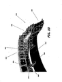
- FIG. 3 is an end view of the nozzle end of the engine according to the first embodiment.
- FIG. 4 is a partially schematic section view of the variable area nozzle assembly portion according to the first embodiment
- FIG. 5 is another partially schematic section view of the variable area nozzle assembly according to the first embodiment.
- FIG. 6 is a partially schematic, exploded section view of the variable area nozzle assembly according to the first embodiment.
- FIG. 7 is a partially schematic isolated view of a guide structure of the variable area nozzle assembly according to the first embodiment.
- FIG. 8 is a partially schematic section view of the variable area nozzle assembly according to the first embodiment.
- FIG. 9A is a partial exploded view of a variable area nozzle assembly according to a second embodiment of the invention.
- FIG. 9B is another partial exploded view of the variable area nozzle assembly according to the second embodiment
- FIG. 10 is another partial exploded view of the variable area nozzle assembly according to the second embodiment.
- FIG. 11 is another partial exploded view of the variable area nozzle assembly according to the second embodiment
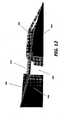
- FIG. 12 is another partial exploded view of the variable area nozzle assembly according to the second embodiment
- FIG. 13 is a partial exploded view of a variable area nozzle assembly according to a third embodiment of the invention.
- FIG. 14 is an isolated view of a guide structure of the variable area nozzle assembly according to the third embodiment.
- FIG. 15 is schematic illustration of an actuation system for the variable area nozzle assembly according to the third embodiment
- FIG. 16 is an isolated view of a stabilizer of the variable area nozzle assembly according to the third embodiment
- FIG. 17 is a section view of the variable area nozzle assembly according to the third embodiment.
- FIG. 18 is another section view of the variable area nozzle assembly according to the third embodiment
- FIG. 19 is another section view of the variable area nozzle assembly according to the third embodiment.
- FIG. 20 is another section view of the variable area nozzle assembly according to the third embodiment
- FIG. 21 is a partial exploded view of a variable area nozzle assembly according to a fourth embodiment of the invention.
- FIG. 22 is an isolated view of a guide structure of the variable area nozzle assembly according to the fourth embodiment.
- FIG. 23 is a section view of the variable area nozzle assembly according to the fourth embodiment
- FIG. 24 is another section view of the variable area nozzle assembly according to the fourth embodiment
- FIG. 25 is another section view of the variable area nozzle assembly according to the fourth embodiment.
- FIG. 26 is another section view of the variable area nozzle assembly according to the fourth embodiment.
- FIG. 27 is a partial exploded view of an actuator for a variable area nozzle assembly according to a fifth embodiment of the invention.
- FIG. 28 is schematic illustration of an actuation system for the variable area nozzle assembly according to the fifth embodiment.
- F IGS. 29A-29C illustrate the actuator according to the fifth embodiment of the invention in various modes of operation.
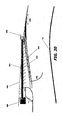
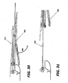
- FIG. 30 is a section view of the variable area nozzle assembly according to the fifth embodiment.
- FIG. 31 is another section view of the variable area nozzle assembly according to the fifth embodiment.
- FIGS. 1-8 show a variable area nozzle assembly according to a first embodiment of this invention.
- the engine 10 includes a trailing edge variable area fan nozzle (VAFN) assembly 12 having a translating ring assembly 50 that may be adjusted, for example, as the engine 10 operates under varying flight conditions. As stated, such an adjustment can cause a shift in the engine's operating line.
- the translating ring assembly 50 is translated (i.e., moved fore and aft) to vary the nozzle exit area in order to optimize engine operation and to adjust an amount of engine bypass flow spilled through an upstream exit in the nozzle assembly 12.
- By bleeding or spilling off excess fan flow through the upstream exit of the nozzle assembly 12 lower fan pressure ratios for the same amount of delivered mass flow can be obtained, thereby increasing stall margins and avoiding engine malfunction and shutdown.
- variable area fan nozzle assembly 12 of the present invention is shown in the context of a gas turbine jet aircraft engine.
- the engine 10 may be mounted to a wing or fuselage of an aircraft, for example, by a pylon or other, similar support (not illustrated).
- the engine 10 includes an engine core 16 and a nacelle 18.
- the engine core 16 is housed in a core cowl 19.
- a fan 20 is mounted adjacent to an upstream end of the nacelle 18, and includes a series of fan blades 22 that are rotated about the engine centerline C L during engine operation so as to draw a flow of air into an inlet end 26 of the engine 10.
- An annular bypass duct 24 is defined between the engine core 16 and the nacelle 18. The air flow drawn into the engine 10 is accelerated by the rotating fan blades 22. A portion of the air flow is directed into and through a compressor (not illustrated) within the engine core 16.
- the air flow through the engine core 16 is initially passed through the compressor to increase the air flow pressure, after which the pressurized air is passed through a combustor (not shown), where it is mixed with fuel and ignited.
- the combustion of the fuel and air mixture within the combustor causes the air to expand which in turn drives a series of turbines at the rear of the engine, indicated generally at 38, to rotate and in turn to provide power to the fan 20.
- bypass flow accelerated by the rotating fan blades 22 passes through the bypass duct 24, past stators 40, and out through the nozzle assembly 12.
- the bypass flow provides the main engine thrust.
- the high pressure heated exhaust gases from the combustion of the fuel and air mixture are directed through the nozzle assembly 12 out of the rear of the engine core 16.
- the translating ring assembly 50 can be a ring-like annular airfoil structure mounted at the trailing end of a thrust reverser 80, adjacent to and circumscribing the engine core cowl 19. The area between the trailing edge of the ring assembly 50 and the core cowl 19 defines the nozzle exit area 52 for the nozzle assembly 12. As shown in FIGS. 1 and 3 , the ring assembly 50 can comprise an arcuate first ring section 54 and an arcuate second ring section 56, each ring section 54, 56 being axially translatable in the direction of the bidirectional arrow 58. Translation of the ring assembly 50 effects a desired size of an upstream exit 60 and varies the outlet geometric and exit area 52 of the nozzle 12 outlet for the engine bypass flow. The ring assembly 50 can be translated, for example, by a plurality of ring actuators 70.
- the thrust reverser 80 may he adjacent to and forward of the translating ring assembly 50 to block and redirect the bypass flow in the bypass duct 24 into a thrust reversing vector.
- the thrust reverser 80 and the translating ring assembly 50 are in stowed or closed positions.
- the thrust reverser 80 can comprise an arcuate first sleeve or cowl section 82 and an opposed arcuate second sleeve or cowl section 84 (shown in FIG. 3 ).
- the thrust reverser sleeve sections 82, 84 can be axially translatable in the direction of the bidirectional arrow 86 by a plurality of sleeve actuators 90.
- the thrust reverser sleeve sections 82, 84 are translatable over a series of cascade vanes 88.
- the cascade vanes 88 are indicated by dashed lead lines in FIG 1 because they are not visible when the thrust reverser 80 is in the stowed position.
- Axial translation of the sleeve sections 82, 84 in the fore and aft directions allows the bypass air flow to be passed through the cascade vanes 88 to generate a thrust-reversing vector.
- FIG. 3 is a partial section view of the aft end of the engine 10, and illustrates the arrangement of the ring and sleeve actuators 70, 90, respectively, around the periphery of the engine 10.
- the sleeve half section 82 and the ring half-section 54 cooperate to generally define an approximately 180 degree sector of the combined thrust reverser and translating ring structure.
- sleeve half section 84 and ring half section 56 cooperate to generally define an opposed approximately 180 degree sector of the thrust reverser and translating ring structure. Together, these approximate 180 degree sectors cooperate to define the entire approximate 360 degree thrust reverser-translating ring structure.
- each thrust reverser sleeve half-section 82, 84 of the thrust reverser 80 can be translatable by one or more (three are shown) peripherally spaced sleeve actuators 90 fixedly mounted in the nacelle 18. In the embodiment shown, three actuators 90 are used for each sleeve half-section 82, 84.
- Each half-section 54, 56 of the translating ring assembly 50 similarly can be translated by one or more (three are shown) peripherally spaced ring actuators 70.
- Ring actuators 70 can be mounted on an adjacent thrust reverser sleeve section 82, 84, respectively.
- the ring actuators 70 could be powered by, for example, electricity, mechanical, pneumatics, hydraulics, or other means, with appropriate power cables and conduits (not shown) passing via pre-defined passages between or above the thrust reverser cascade boxes or pivot doors.
- the number and arrangement of ring and sleeve actuators 70, 90 may be varied, for example, according to the thrust reverser and ring assembly configuration, and according to other factors.
- the ring sections 54, 56 may be mounted in, for example, upper and lower guide structures 102 located at each end of corresponding sleeve sections 82, 84, respectively.
- FIG. 7 is an isolated view of a guide structure 102.
- Guide tubes 104 may be mounted in the nacelle 18 and may extend into the ring sections 54, 56 to stabilize the sections 54, 56 against undesirable translation and/or vibration.
- Guide tubes may alternatively be mounted in the thrust reverser 80.
- the translating ring assembly 50 may be a continuous (e.g., one-piece) or, as shown in FIG. 3 , a continuing (e.g., split or multi-section) generally annular ring having an airfoil cross section.
- the upstream exit 60 (formed when the ring assembly 50 moves in the aft direction away from the sleeve sections 82, 84) therefore can have the form of a generally annular gap extending around the perimeter of the rear of the nacelle 18.
- Other outlet shapes can also be used, e.g., oval, etc.
- the generally annular gap between the ring sections 54, 56 and the sleeve sections 82, 84 can be continuous, for example, or interrupted at one or more locations, such as, for example, at points of bifurcation or other separation of the ring assembly 50.
- the bypass duct 24 may also be interrupted at one or more locations.
- FIGS. 4-7 elements that are obscured or partially obscured due to intervening elements are indicated by dashed lead lines.
- FIG. 4 is a partial view of the mounting structure for a first ring section 54 of the translating ring assembly 50 and the corresponding, adjacent first sleeve section 82 of the thrust reverser 80.
- the second ring section 56 of the translating ring assembly 50 and the second sleeve section 84 of the thrust reverser 80 which are shown in FIGS. 1 and 3 , can be mounted in a similar manner.
- the thrust reverser 80 is in a stowed position, covering the cascade vanes 88.
- the translating ring assembly 50 is in an open or deployed position so that an upstream exit 60 is defined between the first ring section 54 and the first sleeve section 84.
- the rearward axial translation of the first ring section 54 to the deployed position is indicated by the arrow A.
- the ring actuators 70 can extend from the sleeve section 82, across the upstream exit 60, and connect to a fore end of the ring section 54.
- the guide tubes 104 can also extend from the sleeve section 82, across the upstream exit 60, and connect to the fore end of the ring section 54.
- a sleeve actuation cable 96 can connect to each sleeve actuator 90 for power and to provide simultaneous actuation of each actuator 90.
- FIG. 5 shows the thrust reverser 80 in a deployed position and the translating ring assembly 50 in the open position.
- the rearward axial translation of the first sleeve section 82 from the position shown in FIG. 4 to the deployed position is indicated by the arrow B.
- Rearward translation of the sleeve section 82 exposes the cascade vanes 88 during operation of the thrust reverser 80.
- the ring section 54 can also be translated rearwardly during operation of the thrust reverser 80, as shown in this embodiment Translation of the ring section 54 at the same time that the thrust reverser 80 is deployed, may be optional because the bypass flow is rerouted through the cascade vanes 88.
- FIG. 6 is a partial, exploded view with the first sleeve section 82 and its corresponding first ring section 54, illustrated separate from the surrounding mounting structure.
- FIG. 7 is a partial section isolated view taken through one of the guide structures 102.
- a beam 106 can be fixedly attached to a transverse bulkhead 110 that extends 180 degrees and can include axially (e.g., parallel to the centerline of the engine 10) extending guide tracks 108 attached thereto.
- the bulkhead 110 may be integral with or otherwise fixedly mounted to the engine nacelle 18 ( FIG. 1 ).
- the thrust reverser sleeve section 82 can be connected to axially extending track bars 114 ( FIG. 7 ) that are slidably received within the guide tracks 108 of the fixed beam 106.
- the thrust reverser sleeve section 82 is thereby slidably mounted with respect to the nacelle 18.
- the thrust reverser sleeve section 82 can also include an axially extending track guide 116 in which a translating ring track bar 120 is slidably received.
- the translating ring track bar 120 can be connected to the first ring section 54, and the ring section 54 axially translates as the track bar 120 slides within the track guide 116.
- the ring section 54 is thereby slidably mounted with respect to the sleeve section 82 of the thrust reverser 80.
- the translating sleeve section 82 and the track bar 120 can be powered through conventional means, such as mechanical, electric, hydraulic or pneumatic or other equivalent means.
- FIG. 8 illustrates one method of operating the ring section 54 to achieve flow diversion in accordance with this invention.
- the size of the upstream exit 60 and the nozzle exit area 52 can be varied in order to achieve differing engine operating parameters.
- the upstream exit 60 essentially acts as a "bleed" exit that spills airflow traveling through the bypass duct 24.
- FIG. 8 shows a partial section of a downstream portion of the nozzle assembly 12 illustrating a portion of the bypass air flow, indicated by the curved arrows, being bled through the annular upstream exit 60 in one mode of operation of the nozzle assembly 12.
- FIG. 8 shows a partial section of a downstream portion of the nozzle assembly 12 illustrating a portion of the bypass air flow, indicated by the curved arrows, being bled through the annular upstream exit 60 in one mode of operation of the nozzle assembly 12.
- the first ring section 54 of the ring 50 and the first sleeve section 82 of the thrust reverser 80 are shown in section, along with associated ring and sleeve actuators 70, 90, respectively, used for axial translation of the sections 54, 82.
- the second ring section 56 may be similarly constructed and arranged with respect to the second sleeve section 84.
- the thrust reverser 80 can include blocker doors 134 that are operatively coupled to the first sleeve section 82 and are pivotable in the direction of the curved arrow 136 thereby to block and redirect the bypass flow into a thrust reversing vector.
- a high pressure seal 130 may be disposed between the sections 82, 54, at the trailing edge of the translating sleeve section 82.
- the seal 130 can operate to substantially seal any gap between the sections 82, 54 and thereby close the upstream exit 60.
- the ring and sleeve actuators 90, 70 can be, for example, mechanical, hydraulic, pneumatic or electric actuators.
- the ring actuator 70 is a constant opening air spring damper with hydraulic closing override
- the sleeve actuator 90 is an electric actuator.
- FIGS. 9A-12 illustrate a variable area nozzle assembly 212 according to a second embodiment of the invention.
- the nozzle assembly 212 may be mounted to a nacelle as generally illustrated in FIG. 1 , however with no intervening thrust reverser. Therefore, elements within the embodiment shown in FIG. 9A-12 that are analogous to elements in FIGS. 1-8 use a similar reference numbering system, but are preceded by a " 2 " or "3.”
- FIGS. 9A and 9B are partial cutaway illustrations of the variable area nozzle assembly 212 according to the second embodiment of the invention.
- the nozzle assembly 212 includes a translating ring assembly (removed for ease of illustration and not shown in FIGS. 9A and 9B ) comprised of two ring sections, of which one ring section 254 is illustrated in FIGS. 9A and 9B .
- the ring section 254 is in the closed (i.e., axially fore) position
- FIG. 9B illustrates the ring section 254 in the open or deployed (i.e., axially aft) position.
- the ring section 254 can be mounted at the aft end of an engine.
- Peripherally spaced translating ring actuators 270 may be mounted to a bulkhead 310 that is fixedly mounted to the nacelle Guide tubes 304 may also be fixedly mounted to the bulkhead 310 at one end, and received in the ring section 254 at their opposite ends.
- the translating ring actuators 270 can act in unison to translate the ring section 254 in the direction of the bidirectional arrow 258. Referring to FIG. 9B , actuator shafts 272 of the ring actuators 270 can pass through a blister fairing 320 located fore of the ring section 254.
- Upstream fairings 324 may be provided at the points where the actuator shafts 272 pass through the blister fairing 320 in order to reduce drag induced by the actuators 270.
- downstream fairings 328 may be provided at the points where the actuator shafts 272 are received in the ring section 254.
- each end of the blister fairing 320 can include an upstream portion 332 of a beaver tail split fairing 330, and a downstream portion 334 of the fairing 330 can be connected to and translatable with the translating ring section 254. Translation of the translating ring section 254 in the direction of the bidirectional arrow 258 can create an upstream exit 260 between the translating ring section 254 and the blister fairing 320.
- the aft edge of the blister fairing 320 can include a bullnose section 255 ( FIG.
- FIG. 12 is a partial, isolated view of the upstream and downstream fairings 324, 328 of the beaver tail split fairing 330.
- fairings 320, 324, 328, 330 of the aforesaid described embodiment can by selectively used in conjunction with other embodiments described herein.
- fairings analogous to fairings 324, 328 could be used in conjunction with the translating sleeve actuators 90, spaced ring actuators 70, or other actuators disclosed herein.
- FIGS. 13-20 illustrate a variable area nozzle assembly 412 according to a third embodiment of the invention.
- the nozzle assembly 412 includes a translating ring assembly 450 and may be mounted to a nacelle 18 as generally illustrated in FIG. 1 .
- the translating ring assembly 450 according to the third embodiment can be comprised of two ring sections, of which a first ring section 454 is illustrated in FIG. 13 .
- the second ring section 456, illustrated schematically in FIG. 15 may be a mirror image of the ring section 454.
- the translating ring section 454 is in the closed or non-deployed position, with no upstream exit defined between the ring section 454 and the thrust reverser sleeve section 482.
- the translating ring assembly 450 is mounted aft of a thrust reverser 460 comprising two translating sleeve section, of which a first sleeve section 462 is illustrated in FIG. 13 .
- the first sleeve section 462 of the thrust reverser 460 can be translated by one or more actuators 464.
- the ring section 454 can be operated by an actuation system including ring actuators 470 located at each end of the first translating ring section 454.
- Stabilizer assemblies 480 connecting the first ring section 454 to the first sleeve section 462 can be spaced along the periphery of the nozzle assembly 412 to reduce undesirable translation and/or vibration (e.g., flutter) of the ring section 454.
- Analogous stabilizer assemblies can be added to other embodiments shown herein where additional stabilization is desired.
- a motor or drive mechanism 482 governs the motion of the ring actuators 470.
- the drive mechanism 482 is connected to a splined coupling 484 by transmission shafting 485 and a gear box 486.
- the splined coupling 484 terminates at the aft end of the sleeve section 462 at a gear box 488, which is coupled to flexible cable shafting 490.
- the flexible shafting 490 is connected to the actuators 470 at each end of the translating ring section 454.
- the drive mechanism 482 is thereby coupled to the ring actuators 470 to effect translation of the ring section 454.
- the translating ring section 454 may be mounted in, for example, upper and lower guide structures 500 located at each end of the ring section 454. Each translating ring actuator 470 can be operably coupled with a guide structure 500, as discussed below with reference to FIG. 14 .
- FIG. 14 is a partial view of a guide 500 and associated actuator 470 at one end of the ring section 454.
- the thrust reverser sleeve section 462 forward of the ring section 454 can be connected to an axially extending beam 502 of the guide 500.
- the ring section 454 is mounted to a track bar 503 that is slidably mounted on the beam 502.
- the ring section 454 is thereby slidably mounted with respect to the sleeve section 462.
- the guide 500 includes a slider 504 that receives a screw shaft 506.
- the screw shaft 506 can be coupled to a gear box 508 that converts rotary movement of the flexible actuator cable 490 to rotary movement of the screw shaft 506.
- Rotation of the screw shaft 506 within the slider 504 translates the track 503 along the beam 502, which can be used to effect translation of the ring section 454 in the direction of the bidirectional arrow 458.
- the aforesaid described actuator system could be used in each of the actuator embodiments discussed elsewhere herein.
- FIG. 15 is a schematic view of an actuation and control system that may be used to actuate translation of the translating ring assembly 450 illustrated in FIGS. 13 and 14 .
- the drive unit 482 can include a motor 516 coupled to a gear box 520. Rotational motion provided by the motor 516 is sequentially transmitted through the gear box 520, the transmission shafting 485, the gear boxes 486, the splined couplings 484, the actuator cable 490, and ultimately to the ring actuators 470 through the gear boxes 488 to provide axial translation of the ring sections 454, 456.
- the motor 516 can be coupled to a host controller unit 526, which is coupled to a full authority digital engine controller (FADEC) 540.
- the FADEC 540 can thereby control actuation of the ring sections 454, 456 of the translating ring assembly 450.
- the FADEC 540 can also control actuation of a thrust reverser.
- Linear variable differential transformers 550 can be coupled to the ring sections 454, 456 to provide position feedback to the FADEC 540.
- FIG. 16 is an isolated view of a stabilizer assembly 480.
- the stabilizer assembly 480 can include an aft portion 580 fixedly mounted to the translating ring section 454, and a guide portion 582 fixed to the translating sleeve 482 of the thrust reverser 480.
- the aft portion 580 can be axially slidable within the guide portion 582 with relatively low clearance to minimize unwanted translation and/or vibration (e.g., flutter) of the ring section 454.
- FIG. 17 is a sectional partial view of a downstream portion of the nozzle assembly 412, taken along a longitudinal section that passes through a stabilizer assembly 480.
- the translating ring section 454 in FIG. 17 is translatable in the direction of the bidirectional arrow 458 to create an upstream exit forward of the section 454, as discussed above with reference to the embodiment illustrated in FIG. 8 .
- Blocker doors 586 are operatively coupled to the first sleeve section 462 and pivotable in the direction of the curved arrow 588 thereby to block and redirect the bypass flow through cascade vanes 590 to produce a thrust reversing vector.
- FIG. 18 is a sectional partial view of a downstream portion of the nozzle assembly 412, taken along a longitudinal section that passes through a translating ring actuator 470 at one end of the translating ring section 454.
- FIG. 19 is a sectional partial view of a downstream portion of the nozzle assembly 412, taken along a longitudinal section that passes through an actuator 464 of the thrust reverser 460.
- FIG. 20 is a sectional partial view of a downstream portion of the nozzle assembly 412, taken along a longitudinal section that passes through a splined coupling 484.
- FIGS. 21-26 illustrate a variable area nozzle assembly 612. according to a fourth embodiment of the invention.
- the nozzle assembly 612 may be mounted to a nacelle as generally illustrated in FIG. 1 .
- FIG. 21 is a partially exploded, cutaway illustration of the variable area nozzle assembly 612, which has a translating ring assembly 650 at an aft end of the nozzle assembly.
- FIG. 22 is an isolated view of an actuator of the translating ring assembly 650. Translation of the translating ring assembly 650 can be effected by an actuation system such as, for example, the actuation system illustrated in FIG.15 .
- the translating ring assembly 650 can be comprised of two ring sections, of which a first ring section 654 is illustrated in FIG. 21 .
- the second ring section (not illustrated) may be a mirror image of the ring section 654.
- the first translating ring section 654 is in the closed position, with no upstream exit defined forward of the first section 654.
- the ring assembly 650 is mounted aft of a thrust reverser 660 comprising two translating sleeve sections, of which a first sleeve section 662 is illustrated in FIG. 21 .
- the translating sleeve section 662 of the thrust reverser 660 can be translated by one or more actuators 664.
- the ring section 654 can be operated by an actuation system including actuators 670 located at each end of the ring section 654.
- Stabilizer assemblies 680 connecting the ring section 654 to the sleeve section 662 can be spaced along the periphery of the nozzle assembly 612 to reduce undesirable translation and/or vibration (e.g., flutter) of the ring section 654.
- a motor or drive mechanism 682 governs the motion of the ring actuators 670.
- the drive mechanism 682 is connected to a splined coupling 684 by transmission shafting 685 and a gear box 686.
- the splined coupling 684 terminates at the aft end of the sleeve section 662 at a gear box 688, which is coupled to flexible cable shafting 690.
- the flexible cable shafting 690 is connected to the ring actuators 670 at each end of the translating ring section 654.
- the drive mechanism 682 is thereby coupled to the ring actuators 670 to effect translation of the ring section 654.
- the ring section 654 may be translatably mounted in, for example, upper and lower guide structures 700 located at each end of the ring section 654.
- Each actuator 670 can be operably coupled with a guide structure 700, as discussed below with reference to FIG. 22 .
- FIG. 22 is a partial view of a guide 700 and associated actuator 670 at one end of the ring section 654.
- the translating sleeve section 662 forward of the ring section 654 can be connected to an axially extending beam 702 of the guide 700.
- the ring section 654 is mounted to a track bar 703 that is slidably mounted on the beam 702.
- the first translating ring section 654 is thereby slidably mounted with respect to the first thrust reverser sleeve section 662.
- the ring actuator 670 is coupled at one end to a gear box 708 and at its opposite end to the track bar 703.
- the gear box 708 utilizes rotational motion of the flexible cable 690 to cause the actuator 670 to translate the ring section 654 in the direction of the bidirectional arrow 658.
- FIG. 23 is a sectional partial view of a downstream portion of the nozzle assembly 612, taken along a longitudinal section that passes through one of the stabilizer assemblies 680.
- the translating ring section 654 illustrated in FIG. 23 is translatable in the direction of the bidirectional arrow 658 to create an upstream exit forward of the section 654, as discussed above with reference to the embodiment illustrated in FIG. 8 .
- the thrust reverser 660 can include blocker doors 786 that are operatively coupled to the first sleeve section 662 and are pivotable in the direction of the curved arrow 788 thereby to block and redirect the bypass flow through variable depth cascade vanes 790 to produce a thrust reversing vector.
- FIG. 24 is a sectional partial view of a downstream portion of the nozzle assembly 612, taken along a longitudinal section that passes through an actuator 670 at one end of the translating ring section 654.
- FIG. 25 is a sectional partial view of a downstream portion of the nozzle assembly 612, taken along a longitudinal section that passes through an actuator 664 of the thrust reverser 660.
- FIG. 26 is a sectional partial view of a downstream portion of the nozzle assembly 612, taken along a longitudinal section that passes through a splined coupling 684.
- FIGS. 27-31 illustrate an actuator 870 for translating ring sections 854, 856 of a translating ring assembly 650 (illustrated schematically in FIG. 28 ) according to a fifth embodiment of the invention.
- Each translating ring section 854, 856 can include an actuator 870 at each end of the ring section.
- an actuator 870 is shown in a cutaway section of a portion of a variable area nozzle assembly 812.
- the variable area nozzle assembly 812 includes a thrust reverser 860 located forward of the translating ring assembly 650.
- the movable cowl or sleeve of the thrust reverser 860 is present but not shown in FIG. 27 for ease of illustration so that that cascade vanes 990 of the thrust reverser are visible.
- the translating ring assembly 650 and thrust reverser 860 of the nozzle assembly 812 can be, for example, generally similar in structure to those of the variable area nozzle assemblies 412, 612 discussed above.
- the thrust reverser 860 is in the stowed or non-deployed position.
- the translating ring actuator 870 can include a bearing 886 that can be fixedly mounted forward of the thrust reverser 860.
- the bearing 886 is coupled to an extensible shaft 888.
- the shaft 888 is coupled to a spline bush gimbal 890, which is coupled to a sliding spline 894.
- the sliding spline 894 is fixed to a track bar 903, which can be fixed to one end of the translating ring section 854 ( FIG. 28 ).
- the track bar 903 is slidably mounted on a beam 702 that is fixed to a section of the thrust reverser 860.
- the first translating ring section 854 is thereby slidably mounted with respect to the thrust reverser 860.
- the bearing 886 at each end of the translating ring section 854 is coupled to transmission shafting 885. Rotation of the transmission shafting 885 effects translation of the ring section 854.
- FIG. 28 is a schematic view of an actuation and control system that may be used with the translating ring assembly 850.
- a drive unit 882 can include a motor 916 coupled to a gear box 920. Rotation provided by the motor 916 is transmitted through the gear box 920 to the transmission shafting 885. The rotational motion from the transmission shafting 885 is utilized by the actuators 870 at each end of the ring sections 854, 856 to translate the ring sections.
- the motor 916 can be coupled to a host controller unit 926, which is coupled to a full authority digital engine controller (FADEC) 940.
- the FADEC 940 can thereby control actuation of the translating ring sections 854, 856 of the translating ring assembly 850.
- the FADEC 940 can also control actuation of a thrust reverser.
- Linear variable differential transformers 950 can be coupled to the ring sections 854, 856 to provide position feedback information to the FADEC 940.
- FIGS. 29A-29C illustrate an actuator 870 in three operational modes.
- the actuator 890 is fully retracted, corresponding to an operating condition in which the translating ring assembly 850 and the thrust reverser 860 are stowed
- FIG. 29B the actuator 890 is in a deployed state in which the translating ring assembly 850 is deployed and the thrust reverser 860 is stowed.
- FIG. 29C illustrates the actuator 890 where the thrust reverser 860 is deployed.
- FIG. 30 is a sectional partial view of a downstream portion of the nozzle assembly 812, taken along a longitudinal section that passes through an actuator 870 at one end of the translating ring section 854.
- the translating ring section 854 is in a stowed position in FIG. 30 .
- FIG. 31 is a sectional partial view of a downstream portion of the nozzle assembly 812, taken along a longitudinal section that passes through an actuator 870 at one end of the translating ring section 854.
- the translating ring section 854 is in a deployed position in FIG. 31 .
Priority Applications (1)
| Application Number | Priority Date | Filing Date | Title |
|---|---|---|---|
| EP12197068.5A EP2578864B1 (de) | 2007-08-08 | 2008-08-07 | Veränderliche Gebläsedüse mit Bypass-Strom |
Applications Claiming Priority (2)
| Application Number | Priority Date | Filing Date | Title |
|---|---|---|---|
| US95475607P | 2007-08-08 | 2007-08-08 | |
| EP08828100A EP2181262B1 (de) | 2007-08-08 | 2008-08-07 | Veränderliche fächerdüse mit bypass-strom |
Related Parent Applications (2)
| Application Number | Title | Priority Date | Filing Date |
|---|---|---|---|
| EP08828100.1 Division | 2008-08-07 | ||
| EP08828100A Division EP2181262B1 (de) | 2007-08-08 | 2008-08-07 | Veränderliche fächerdüse mit bypass-strom |
Related Child Applications (3)
| Application Number | Title | Priority Date | Filing Date |
|---|---|---|---|
| EP12197068.5A Division-Into EP2578864B1 (de) | 2007-08-08 | 2008-08-07 | Veränderliche Gebläsedüse mit Bypass-Strom |
| EP12197068.5A Division EP2578864B1 (de) | 2007-08-08 | 2008-08-07 | Veränderliche Gebläsedüse mit Bypass-Strom |
| EP12197068.5 Division-Into | 2012-12-13 |
Publications (3)
| Publication Number | Publication Date |
|---|---|
| EP2479414A2 true EP2479414A2 (de) | 2012-07-25 |
| EP2479414A3 EP2479414A3 (de) | 2013-02-20 |
| EP2479414B1 EP2479414B1 (de) | 2015-06-10 |
Family
ID=40364427
Family Applications (3)
| Application Number | Title | Priority Date | Filing Date |
|---|---|---|---|
| EP08828100A Active EP2181262B1 (de) | 2007-08-08 | 2008-08-07 | Veränderliche fächerdüse mit bypass-strom |
| EP12002710.7A Active EP2479414B1 (de) | 2007-08-08 | 2008-08-07 | Verstellbare Fandüse mit Bypass-Strom |
| EP12197068.5A Active EP2578864B1 (de) | 2007-08-08 | 2008-08-07 | Veränderliche Gebläsedüse mit Bypass-Strom |
Family Applications Before (1)
| Application Number | Title | Priority Date | Filing Date |
|---|---|---|---|
| EP08828100A Active EP2181262B1 (de) | 2007-08-08 | 2008-08-07 | Veränderliche fächerdüse mit bypass-strom |
Family Applications After (1)
| Application Number | Title | Priority Date | Filing Date |
|---|---|---|---|
| EP12197068.5A Active EP2578864B1 (de) | 2007-08-08 | 2008-08-07 | Veränderliche Gebläsedüse mit Bypass-Strom |
Country Status (4)
| Country | Link |
|---|---|
| US (5) | US9970387B2 (de) |
| EP (3) | EP2181262B1 (de) |
| CN (1) | CN101939528B (de) |
| WO (1) | WO2009029401A2 (de) |
Families Citing this family (138)
| Publication number | Priority date | Publication date | Assignee | Title |
|---|---|---|---|---|
| EP2074301B1 (de) * | 2006-10-12 | 2016-02-24 | United Technologies Corporation | Fan-triebwerk mit schubdüsenkontrolle für start und landung |
| US20080273961A1 (en) | 2007-03-05 | 2008-11-06 | Rosenkrans William E | Flutter sensing and control system for a gas turbine engine |
| US9759087B2 (en) | 2007-08-08 | 2017-09-12 | Rohr, Inc. | Translating variable area fan nozzle providing an upstream bypass flow exit |
| EP2181262B1 (de) | 2007-08-08 | 2012-05-16 | Rohr, Inc. | Veränderliche fächerdüse mit bypass-strom |
| US10167813B2 (en) | 2007-08-23 | 2019-01-01 | United Technologies Corporation | Gas turbine engine with fan variable area nozzle to reduce fan instability |
| US9701415B2 (en) | 2007-08-23 | 2017-07-11 | United Technologies Corporation | Gas turbine engine with axial movable fan variable area nozzle |
| US8074440B2 (en) * | 2007-08-23 | 2011-12-13 | United Technologies Corporation | Gas turbine engine with axial movable fan variable area nozzle |
| US9494084B2 (en) | 2007-08-23 | 2016-11-15 | United Technologies Corporation | Gas turbine engine with fan variable area nozzle for low fan pressure ratio |
| FR2922059B1 (fr) * | 2007-10-04 | 2014-07-04 | Aircelle Sa | Actionneur lineaire telescopique double action a systeme d'entrainement a moteur unique |
| FR2922058B1 (fr) * | 2007-10-04 | 2009-12-04 | Aircelle Sa | Actionneur lineaire telescopique pour deplacer un premier et un second elements relativement a un element fixe |
| US20090226303A1 (en) * | 2008-03-05 | 2009-09-10 | Grabowski Zbigniew M | Variable area fan nozzle fan flutter management system |
| US9074531B2 (en) | 2008-03-05 | 2015-07-07 | United Technologies Corporation | Variable area fan nozzle fan flutter management system |
| US8220738B2 (en) * | 2008-11-26 | 2012-07-17 | Mra Systems, Inc. | Nacelle and method of assembling the same |
| US9188025B2 (en) * | 2008-11-26 | 2015-11-17 | Mra Systems, Inc. | Apparatus for facilitating access to a nacelle interior |
| US9188026B2 (en) * | 2008-11-26 | 2015-11-17 | Mra Systems, Inc. | Apparatus for facilitating access to a nacelle interior and method of assembling the same |
| EP2239449B1 (de) * | 2009-04-06 | 2015-09-30 | Rohr, Inc. | Gondelanordnung für Mantelstromtriebwerke von Flugzeugen |
| EP2278146B1 (de) * | 2009-06-16 | 2013-07-24 | Rohr, Inc. | Betätigungssystem für eine Flachstrahldüse mit Umsetzung verschiedener Bereiche |
| FR2947870B1 (fr) * | 2009-07-09 | 2011-07-08 | Aircelle Sa | Systeme d'actionnement pour element mobile de nacelle de moteur d'aeronef, tel qu'un capot d'inverseur de poussee |
| DE102009033755A1 (de) * | 2009-07-17 | 2011-01-20 | Rolls-Royce Deutschland Ltd & Co Kg | Turbofantriebwerk |
| GB0917057D0 (en) * | 2009-09-29 | 2009-11-11 | Goodrich Actuation Systems Ltd | Thrust reverser actuation |
| US20110120079A1 (en) | 2009-11-24 | 2011-05-26 | Schwark Jr Fred W | Variable area fan nozzle stiffeners and placement |
| US20110120078A1 (en) * | 2009-11-24 | 2011-05-26 | Schwark Jr Fred W | Variable area fan nozzle track |
| US8443586B2 (en) * | 2009-11-24 | 2013-05-21 | United Technologies Corporation | Variable area fan nozzle bearing track |
| FR2954278B1 (fr) * | 2009-12-18 | 2012-01-20 | Aircelle 7303 | Structure support pour inverseur de poussee notamment a grilles |
| US8869507B2 (en) * | 2010-01-13 | 2014-10-28 | United Technologies Corporation | Translatable cascade thrust reverser |
| US9470108B2 (en) | 2010-02-22 | 2016-10-18 | American Airlines, Inc. | Thrust reverser cowl rack |
| FR2957979B1 (fr) * | 2010-03-25 | 2012-03-30 | Aircelle Sa | Dispositif d'inversion de poussee |
| FR2959488B1 (fr) * | 2010-04-28 | 2012-05-18 | Aircelle Sa | Nacelle pour moteur d'aeronef a inverseur de poussee a grilles et a tuyere adaptative |
| US8875486B2 (en) | 2010-05-17 | 2014-11-04 | Rohr, Inc. | Guide system for nacelle assembly |
| US10041442B2 (en) | 2010-06-11 | 2018-08-07 | United Technologies Corporation | Variable area fan nozzle |
| US8511973B2 (en) | 2010-06-23 | 2013-08-20 | Rohr, Inc. | Guide system for nacelle assembly |
| US8800261B2 (en) * | 2010-07-19 | 2014-08-12 | United Technologies Corporation | Gas turbine engine with noise attenuating variable area fan nozzle |
| US8997497B2 (en) * | 2010-10-29 | 2015-04-07 | United Technologies Corporation | Gas turbine engine with variable area fan nozzle |
| US8978356B2 (en) * | 2010-12-03 | 2015-03-17 | The Boeing Company | Thrust reverser and variable area fan nozzle actuation system and method |
| US9416751B2 (en) * | 2010-12-07 | 2016-08-16 | Hamilton Sundstrand Corporation | Actuation system |
| US20120139531A1 (en) * | 2010-12-07 | 2012-06-07 | Hamilton Sundstrand Corporation | Position detecting system |
| US8713911B2 (en) * | 2010-12-15 | 2014-05-06 | Woodward Hrt, Inc. | System and method for operating a thrust reverser for a turbofan propulsion system |
| US8720183B2 (en) * | 2011-03-02 | 2014-05-13 | Spirit Aerosystems, Inc. | Thrust reverser translating sleeve assembly |
| US9021813B2 (en) | 2011-07-18 | 2015-05-05 | The Boeing Company | Cable-actuated variable area fan nozzle with elastomeric seals |
| FR2978800B1 (fr) | 2011-08-05 | 2014-05-23 | Aircelle Sa | Nacelle de turboreacteur a tuyere variable |
| US20130078081A1 (en) * | 2011-09-28 | 2013-03-28 | Honeywell International Inc. | Vafn systems with improved drive coupling assemblies and brakes |
| US9086034B2 (en) * | 2011-10-13 | 2015-07-21 | Rohr, Inc. | Thrust reverser cascade assembly with flow deflection shelf |
| US9803663B2 (en) | 2011-10-27 | 2017-10-31 | Parker-Hannifin Corporation | Telescoping fluid porting tube |
| US9151183B2 (en) * | 2011-11-21 | 2015-10-06 | United Technologies Corporation | Retractable exhaust liner segment for gas turbine engines |
| US20130145743A1 (en) * | 2011-12-08 | 2013-06-13 | Honeywell International Inc. | Case assembly with fuel driven actuation systems |
| US9316112B2 (en) * | 2011-12-21 | 2016-04-19 | Rohr, Inc. | Variable area fan nozzle with drive system health monitoring |
| EP2798184A4 (de) * | 2011-12-30 | 2015-08-12 | United Technologies Corp | Gasturbinenmotor mit lüfterdüse mit veränderlichem bereich für niedriges lüfterdruckverhältnis |
| SG11201403586QA (en) * | 2011-12-30 | 2014-07-30 | United Technologies Corp | Gas turbine engine with fan variable area nozzle to reduce fan instability |
| US8727275B2 (en) | 2012-01-27 | 2014-05-20 | Rohr, Inc. | Nacelle |
| US8869508B2 (en) | 2012-01-31 | 2014-10-28 | United Technologies Corporation | Gas turbine engine variable area fan nozzle control |
| US9394852B2 (en) | 2012-01-31 | 2016-07-19 | United Technologies Corporation | Variable area fan nozzle with wall thickness distribution |
| US9593628B2 (en) | 2012-01-31 | 2017-03-14 | United Technologies Corporation | Gas turbine engine variable area fan nozzle with ice management |
| US8375699B1 (en) * | 2012-01-31 | 2013-02-19 | United Technologies Corporation | Variable area fan nozzle with wall thickness distribution |
| US20130195647A1 (en) * | 2012-01-31 | 2013-08-01 | Marc J. Muldoon | Gas turbine engine bearing arrangement including aft bearing hub geometry |
| US20130340435A1 (en) * | 2012-01-31 | 2013-12-26 | Gregory M. Savela | Gas turbine engine aft spool bearing arrangement and hub wall configuration |
| US9476320B2 (en) | 2012-01-31 | 2016-10-25 | United Technologies Corporation | Gas turbine engine aft bearing arrangement |
| US9255546B2 (en) * | 2012-02-02 | 2016-02-09 | Spirit AreoSystems, Inc. | Cascade-style variable area fan duct nozzle |
| US9783315B2 (en) * | 2012-02-24 | 2017-10-10 | Rohr, Inc. | Nacelle with longitudinal translating cowling and rotatable sleeves |
| FR2987600B1 (fr) | 2012-03-02 | 2014-02-28 | Aircelle Sa | Nacelle aplatie de turboreacteur |
| US9097209B2 (en) | 2012-03-27 | 2015-08-04 | United Technologies Corporation | Gas turbine engine thrust reverser system |
| US9194296B2 (en) | 2012-05-18 | 2015-11-24 | Pratt & Whitney Canada Corp. | Inner bypass duct wall attachment |
| US9303590B2 (en) | 2012-05-22 | 2016-04-05 | Spirit Aerosystems, Inc. | Variable area fan nozzle actuation system |
| US9482180B2 (en) | 2012-05-24 | 2016-11-01 | The Boeing Company | Thrust reverser system |
| FR2993860B1 (fr) * | 2012-07-24 | 2019-06-21 | Rohr, Inc. | Tuyere de soufflante a section variable a translation de grille arriere |
| WO2014051667A1 (en) * | 2012-09-28 | 2014-04-03 | United Technologies Corporation | Divot for blocker doors of thrust reverser system |
| US10145335B2 (en) * | 2012-09-28 | 2018-12-04 | United Technologies Corporation | Turbomachine thrust reverser |
| WO2014116308A2 (en) * | 2012-10-10 | 2014-07-31 | United Technologies Corporation | Geared turbine engine with a d-duct and a thrust reverser |
| GB201219366D0 (en) * | 2012-10-29 | 2012-12-12 | Rolls Royce Deutschland & Co Kg | Aeroengine thrust reverser arrangement |
| US9989009B2 (en) * | 2012-10-31 | 2018-06-05 | The Boeing Company | Methods and apparatus for sealing variable area fan nozzles of jet engines |
| US10400621B2 (en) | 2013-03-04 | 2019-09-03 | United Technologies Corporation | Pivot door thrust reverser with variable area nozzle |
| US20160017815A1 (en) * | 2013-03-12 | 2016-01-21 | United Technologies Corporation | Expanding shell flow control device |
| US10240561B2 (en) * | 2013-03-15 | 2019-03-26 | United Technologies Corporation | Aerodynamic track fairing for a gas turbine engine fan nacelle |
| WO2014143267A1 (en) * | 2013-03-15 | 2014-09-18 | United Technologies Corporation | Gas turbine engine with low fan noise |
| US9447749B2 (en) | 2013-04-02 | 2016-09-20 | Rohr, Inc. | Pivoting blocker door for thrust reverser |
| US9581109B1 (en) | 2013-04-11 | 2017-02-28 | Geoffrey P. Pinto | Axially translating and radially tilting fan nozzle segments with combined actuation and position sensing |
| US10040563B1 (en) * | 2013-04-11 | 2018-08-07 | Geoffrey P. Pinto | Dual panel actuator system for jet engines |
| US9581145B2 (en) * | 2013-05-14 | 2017-02-28 | The Boeing Company | Shape memory alloy actuation system for variable area fan nozzle |
| FR3005697B1 (fr) * | 2013-05-14 | 2017-08-25 | Aircelle Sa | Ensemble propulsif pour aeronef |
| FR3006378B1 (fr) | 2013-05-29 | 2015-05-15 | Aircelle Sa | Nacelle de turboreacteur comportant un dispositif d'inversion de pousse a portes, comprenant des flancs interieurs sur les cotes de l'ouverture |
| US9650991B2 (en) | 2013-06-27 | 2017-05-16 | The Boeing Company | Pivoting ring petal actuation for variable area fan nozzle |
| CN103470400B (zh) * | 2013-07-24 | 2015-09-09 | 南京航空航天大学 | 一种进出口形状可控的吸气式高超声速飞行器排气喷管的设计方法 |
| US9885253B2 (en) * | 2013-10-07 | 2018-02-06 | Rohr, Inc. | Hybrid inner fixed structure with metallic and composite construction |
| CN103575516B (zh) * | 2013-10-08 | 2016-01-27 | 北京动力机械研究所 | 用于可调尾喷管的喉道涨缩灵活性检测装置 |
| FR3011820B1 (fr) * | 2013-10-11 | 2017-03-31 | Aircelle Sa | Nacelle pour moteur d'aeronef a tuyere de section variable |
| US9488130B2 (en) | 2013-10-17 | 2016-11-08 | Honeywell International Inc. | Variable area fan nozzle systems with improved drive couplings |
| US20150107222A1 (en) * | 2013-10-18 | 2015-04-23 | Rohr, Inc. | Thrust reverser fan ramp partially formed on aft end of fan case |
| US20150108247A1 (en) * | 2013-10-21 | 2015-04-23 | Rohr, Inc. | Inverted track beam attachment flange |
| US9650993B2 (en) | 2013-10-23 | 2017-05-16 | Honeywell International Inc. | Rotary hydraulic motor driven hybrid thrust reverser actuation system with end-of-stroke snubbing |
| GB201322380D0 (en) | 2013-12-18 | 2014-02-05 | Rolls Royce Plc | Gas turbine cowl |
| FR3016863B1 (fr) * | 2014-01-29 | 2017-05-26 | Snecma | Nacelle pour turboreacteur d'avion |
| US9617922B2 (en) * | 2014-03-27 | 2017-04-11 | Hamilton Sundstrand Corporation | Jet engine actuation system |
| US9869275B2 (en) * | 2014-04-24 | 2018-01-16 | Rohr, Inc. | Single actuator variable area fan nozzle system and method |
| US10077739B2 (en) * | 2014-04-24 | 2018-09-18 | Rohr, Inc. | Dual actuation system for cascade and thrust reverser panel for an integral cascade variable area fan nozzle |
| US10161356B2 (en) * | 2014-06-02 | 2018-12-25 | Ge Aviation Systems Llc | Integrated thrust reverser actuation system |
| FR3023324B1 (fr) * | 2014-07-01 | 2020-04-24 | Safran Nacelles | Inverseur de poussee d’une nacelle de turboreacteur, comprenant des decoupes d’evitement du bec mobile de l’aile |
| US10502159B2 (en) | 2014-10-01 | 2019-12-10 | Hamilton Sundstrand Corporation | Electric boost actuation system for translating rings |
| DE102014223109A1 (de) | 2014-11-12 | 2016-05-12 | Rolls-Royce Deutschland Ltd & Co Kg | Triebwerksverkleidung einer Gasturbine mit Schubumkehrvorrichtung und verstellbarer Ausströmdüse |
| FR3031727B1 (fr) * | 2015-01-21 | 2019-07-12 | Safran Nacelles | Dispositif d’inversion de poussee a grilles mobiles et berceau pour nacelle pour mat du type corps |
| DE102015203219A1 (de) * | 2015-02-23 | 2016-08-25 | Rolls-Royce Deutschland Ltd & Co Kg | Triebwerksverkleidung einer Gasturbine mit Schubumkehrvorrichtung und im Querschnitt verstellbarer Ausströmdüse |
| FR3033841B1 (fr) * | 2015-03-17 | 2017-04-28 | Aircelle Sa | Inverseur de poussee pour nacelle de turboreacteur d’aeronef |
| US9951717B2 (en) | 2015-04-15 | 2018-04-24 | Hamilton Sundstrand Corporation | Asymmetric load compensation system |
| US10422301B2 (en) * | 2015-07-13 | 2019-09-24 | The Boeing Company | Telescoping electrical cable |
| CN105134408B (zh) * | 2015-09-18 | 2017-09-22 | 中国航空工业集团公司沈阳发动机设计研究所 | 一种二元塞式喷管单作动系统控制机构 |
| US10378479B2 (en) | 2015-10-19 | 2019-08-13 | General Electric Company | Variable effective area fan nozzle |
| US10197007B2 (en) * | 2016-01-14 | 2019-02-05 | General Electric Company | Method and system for controlling core cowl vent area |
| EP3193003A1 (de) * | 2016-01-15 | 2017-07-19 | Goodrich Actuation Systems Ltd. | Architektur eines schubumkehrbetätigungssystems |
| US20170283081A1 (en) * | 2016-04-05 | 2017-10-05 | Rohr, Inc. | Securing a translating fanlet for an aircraft propulsion system nacelle |
| CN106194494B (zh) * | 2016-08-09 | 2018-01-05 | 南京理工大学 | 一种用于微型涡喷发动机加力燃烧室的可调喷管 |
| US10648428B2 (en) | 2016-08-24 | 2020-05-12 | Honeywell International Inc. | Aircraft thrust reverser system with hydraulic assist device |
| US10352273B2 (en) | 2016-11-08 | 2019-07-16 | Rohr, Inc. | Track beam with composite lug |
| US11022071B2 (en) * | 2016-12-21 | 2021-06-01 | The Boeing Company | Load distribution panel assembly, system and method |
| CN109209676B (zh) * | 2017-06-30 | 2019-12-20 | 中国航发商用航空发动机有限责任公司 | 一种反推力装置阻流门密封机构 |
| EP3450736A1 (de) | 2017-09-04 | 2019-03-06 | Brandenburgische Technische Universität Cottbus-Senftenberg | Strahltriebwerk mit schubdüse variabler geometrie sowie schubumkehrvorrichtung |
| EP3896272A1 (de) * | 2017-09-28 | 2021-10-20 | Goodrich Actuation Systems Limited | Verbessertes verriegelungssystem und drehmomentbegrenzer für einen elektrisch betätigten schubumkehrer |
| US10393065B2 (en) | 2017-11-09 | 2019-08-27 | United Technologies Corporation | Variable nozzle apparatus |
| GB201720950D0 (en) | 2017-12-15 | 2018-01-31 | Short Brothers Plc | Variable area fan nozzle for turbofan aircraft engine |
| FR3075760B1 (fr) * | 2017-12-21 | 2020-01-31 | Safran Nacelles | Nacelle de moteur d’aeronef |
| CN109956044B (zh) * | 2017-12-22 | 2022-03-11 | 空中客车运营简化股份公司 | 喷气发动机的短舱 |
| PL235797B1 (pl) | 2018-02-21 | 2020-10-19 | Gen Electric | Zespół dyszy dzwonowej do silników turbogazowych oraz sposób odwracania ciągu silnika turbowentylatorowego |
| FR3079213B1 (fr) * | 2018-03-23 | 2020-02-28 | Airbus Operations | Nacelle equipee d'un systeme inverseur comportant des portes et des systemes anti-vibration des portes en position stockee |
| US11208970B2 (en) * | 2018-06-28 | 2021-12-28 | Rohr, Inc. | Aft cascade ring design concept |
| RU2734328C2 (ru) * | 2018-08-06 | 2020-10-15 | Акционерное общество "Объединенная двигателестроительная корпорация" (АО "ОДК") | Устройство привода сдвижки реверсивного устройства газотурбинного двигателя |
| CN108844708B (zh) * | 2018-09-11 | 2020-03-10 | 中国空气动力研究与发展中心低速空气动力研究所 | 一种引射式短舱音速喷嘴组合排列方法 |
| FR3086007B1 (fr) * | 2018-09-18 | 2020-09-04 | Safran Nacelles | Nacelle de turboreacteur avec un inverseur de poussee a grilles comprenant un secteur de commande des volets |
| FR3087498B1 (fr) * | 2018-10-22 | 2021-03-05 | Airbus Operations Sas | Turboreacteur comportant une nacelle equipee d’un systeme d’inversion de poussee mobile en translation et d’un carter de soufflante equipe de supports |
| CN109882312A (zh) * | 2019-03-18 | 2019-06-14 | 北京航空航天大学 | 一种双层套筒式反推装置 |
| GB201906164D0 (en) * | 2019-05-02 | 2019-06-19 | Rolls Royce Plc | Gas turbine engine |
| US20210025352A1 (en) * | 2019-07-25 | 2021-01-28 | Gulfstream Aerospace Corporation | Propulsion system for an aircraft and method of manufacturing a propulsion system for an aircraft |
| US11066179B2 (en) * | 2019-09-09 | 2021-07-20 | Rohr, Inc | Fire seal assembly for nacelle doors |
| US11512665B2 (en) * | 2020-03-20 | 2022-11-29 | The Boeing Company | Locking linear actuator |
| US11286878B2 (en) | 2020-03-31 | 2022-03-29 | Rolls-Royce North American Technologies Inc. | Variable area nozzle exhaust system with integrated thrust reverser |
| US11781502B2 (en) | 2020-05-05 | 2023-10-10 | Rohr, Inc. | Actuation system for a thrust reverser of an aircraft propulsion system |
| CN112761823B (zh) * | 2020-12-19 | 2022-03-18 | 湖北航天飞行器研究所 | 一种扩张段侧向引流推力矢量控制喷管 |
| US20230265812A1 (en) * | 2022-02-18 | 2023-08-24 | Stephen Michael Roberts | Variable Area Fan Nozzle Actuation System |
| CN115163328B (zh) * | 2022-04-24 | 2023-01-17 | 中国航发四川燃气涡轮研究院 | 一种用于二元矢量喷管的改进型外调节结构 |
| US11873781B1 (en) * | 2022-08-01 | 2024-01-16 | Rohr, Inc. | Thrust reverser cascade with one or more flow stabilizers |
| US20240035429A1 (en) * | 2022-08-01 | 2024-02-01 | Rohr, Inc. | Thrust reverser cascade with one or more flow disrupters |
| US11891964B1 (en) | 2023-08-14 | 2024-02-06 | Rolls-Royce North American Technologies Inc. | Method of manufacture of plug nozzle with thrust reverser |
Family Cites Families (124)
| Publication number | Priority date | Publication date | Assignee | Title |
|---|---|---|---|---|
| US2510606A (en) * | 1943-05-22 | 1950-06-06 | Lockheed Aircraft Corp | Turbine construction |
| US2950595A (en) | 1954-11-01 | 1960-08-30 | Marquardt Corp | Thrust reverser |
| US3109284A (en) * | 1956-06-14 | 1963-11-05 | Power Jets Res & Dev Ltd | Discharge nozzles for propulsive jets |
| GB841110A (en) * | 1957-03-13 | 1960-07-13 | Rolls Royce | Improvements in or relating to jet propulsion nozzle arrangements |
| GB913699A (de) * | 1959-12-18 | |||
| FR1260040A (fr) | 1960-03-07 | 1961-05-05 | Snecma | Dispositif déviateur de jet |
| US3360308A (en) | 1964-12-23 | 1967-12-26 | Gen Motors Corp | Actuator assembly |
| US3262270A (en) * | 1965-06-07 | 1966-07-26 | Gen Electric | Thrust reverser |
| US3404581A (en) | 1967-04-18 | 1968-10-08 | Sargent Industries | Ball screw actuator |
| US3460762A (en) * | 1967-07-24 | 1969-08-12 | Mc Donnell Douglas Corp | Thrust reverser roller latch |
| US3511055A (en) * | 1968-05-29 | 1970-05-12 | Rohr Corp | Thrust reverser |
| US3572463A (en) * | 1969-04-23 | 1971-03-30 | Rohr Corp | Method and apparatus for suppressing the noise of an aircraft jet engine |
| US3665709A (en) * | 1970-06-04 | 1972-05-30 | Rohr Corp | Thrust reversing apparatus |
| GB1365491A (en) | 1971-01-02 | 1974-09-04 | Dowty Rotol Ltd | Gas turbine ducted fan engines and fans therefor |
| GB1418905A (en) * | 1972-05-09 | 1975-12-24 | Rolls Royce | Gas turbine engines |
| US3779010A (en) | 1972-08-17 | 1973-12-18 | Gen Electric | Combined thrust reversing and throat varying mechanism for a gas turbine engine |
| US3797785A (en) * | 1972-08-31 | 1974-03-19 | Rohr Industries Inc | Thrust modulating apparatus |
| US3981450A (en) * | 1975-09-22 | 1976-09-21 | The United States Of America As Represented By The Secretary Of The Air Force | In-flight modulating thrust reverser |
| GB1583952A (en) * | 1976-07-13 | 1981-02-04 | Short Brothers & Harland Ltd | Gas turbine engines |
| US4337868A (en) | 1980-02-19 | 1982-07-06 | Harnischfeger Corporation | Telescopic crane boom having rotatable extend/retract screws |
| US4375276A (en) | 1980-06-02 | 1983-03-01 | General Electric Company | Variable geometry exhaust nozzle |
| US4407120A (en) | 1980-08-25 | 1983-10-04 | Rohr Industries, Inc. | Thrust reverser geared linkage |
| FR2496766A1 (fr) * | 1980-12-23 | 1982-06-25 | Snecma | Dispositif de guidage de carenage mobile d'un systeme d'inversion de poussee |
| EP0109219A3 (de) | 1982-11-12 | 1985-11-13 | LUCAS INDUSTRIES public limited company | Schubumlenkvorrichtung für einen Gasturbinenmotor |
| US4519561A (en) | 1983-05-23 | 1985-05-28 | Rohr Industries, Inc. | Aircraft thrust reverser mechanism |
| US4521707A (en) | 1983-12-12 | 1985-06-04 | The Boeing Company | Triple redundant electromechanical linear actuator and method |
| JPS61279522A (ja) | 1985-06-05 | 1986-12-10 | Ichikou Eng Kk | 取出機用昇降装置 |
| FR2622929A1 (fr) | 1987-11-05 | 1989-05-12 | Hispano Suiza Sa | Inverseur de poussee de turboreacteur a grilles,a section variable d'ejection |
| US4807434A (en) * | 1987-12-21 | 1989-02-28 | The Boeing Company | Thrust reverser for high bypass jet engines |
| US4994660A (en) * | 1989-04-11 | 1991-02-19 | Hitachi, Ltd. | Axisymmetric vectoring exhaust nozzle |
| FR2651278B1 (fr) | 1989-08-23 | 1994-05-06 | Hispano Suiza | Inverseur a grilles sans capot coulissant pour turboreacteur. |
| US5050803A (en) * | 1989-10-12 | 1991-09-24 | General Electric Company | Actuation system for positioning a vectoring exhaust nozzle |
| FR2669679B1 (fr) | 1990-11-28 | 1994-04-29 | Sud Ouest Conception Aeronauti | Tuyere d'ejection de gaz pour moteur a reaction et moteur a reaction equipe d'une telle tuyere, en particulier moteur du type a flux separes. |
| US5174502A (en) * | 1991-05-10 | 1992-12-29 | General Electric Company | Support for a translating nozzle vectoring ring |
| US5313788A (en) * | 1991-08-07 | 1994-05-24 | General Electric Company | Thrust reversing arrangement for a long duct mixed flow exhaust turbofan engine |
| US5228641A (en) | 1991-08-15 | 1993-07-20 | Rohr, Inc. | Cascade type aircraft engine thrust reverser with hidden link actuator |
| FR2680547B1 (fr) | 1991-08-21 | 1993-10-15 | Hispano Suiza | Inverseur de poussee de turboreacteur ayant un bord de deviation a courbure evolutive. |
| US5209057A (en) * | 1991-10-23 | 1993-05-11 | Rohr, Inc. | Rack and pinion actuation for an aircraft engine thrust reverser |
| US5181676A (en) | 1992-01-06 | 1993-01-26 | Lair Jean Pierre | Thrust reverser integrating a variable exhaust area nozzle |
| GB9215496D0 (en) | 1992-07-21 | 1992-09-02 | Lucas Ind Plc | Lock for an engine thrust reverser |
| US5285637A (en) * | 1992-11-02 | 1994-02-15 | United Technologies Corporation | Seal centering and restraining device for an axisymmetric convergent/divergent nozzle |
| US5328098A (en) * | 1993-07-09 | 1994-07-12 | United Technologies Corporation | Thrust vectoring ejector nozzle |
| GB9320447D0 (en) | 1993-10-05 | 1993-12-22 | Lucas Ind Plc | Lock for an engine thrust reverser |
| GB9326466D0 (en) | 1993-12-24 | 1994-02-23 | Rolls Royce Plc | Thrust reverser control mechanism |
| FR2724208B1 (fr) | 1994-09-07 | 1996-10-18 | Commissariat Energie Atomique | Systeme telescopique |
| US5778659A (en) * | 1994-10-20 | 1998-07-14 | United Technologies Corporation | Variable area fan exhaust nozzle having mechanically separate sleeve and thrust reverser actuation systems |
| US5575147A (en) | 1994-12-22 | 1996-11-19 | United Technologies Corporation | Compact thrust reverser |
| US5655360A (en) | 1995-05-31 | 1997-08-12 | General Electric Company | Thrust reverser with variable nozzle |
| JPH09195853A (ja) | 1995-12-14 | 1997-07-29 | United Technol Corp <Utc> | 可変面積ファンエキゾーストノズル |
| FR2745036B1 (fr) | 1996-02-15 | 1998-04-03 | Hispano Suiza Sa | Inverseur de poussee de turboreacteur a portes associees a un panneau amont |
| US5806302A (en) * | 1996-09-24 | 1998-09-15 | Rohr, Inc. | Variable fan exhaust area nozzle for aircraft gas turbine engine with thrust reverser |
| FR2755730B1 (fr) | 1996-11-14 | 1999-01-08 | Hispano Suiza Sa | Systeme de commande electrique pour inverseur de poussee de turboreacteur |
| US5833140A (en) | 1996-12-12 | 1998-11-10 | United Technologies Corporation | Variable geometry exhaust nozzle for a turbine engine |
| FR2764643B1 (fr) | 1997-06-12 | 1999-07-16 | Hispano Suiza Sa | Inverseur de poussee a portes de turboreacteur a section variable d'ejection |
| GB9825651D0 (en) | 1998-11-23 | 1999-01-13 | Lucas Ind Plc | Actuator |
| US6170254B1 (en) | 1998-12-18 | 2001-01-09 | Rohr, Inc. | Translating sleeve for cascade type thrust reversing system for fan gas turbine engine for an aircraft |
| GB2347126B (en) | 1999-02-23 | 2003-02-12 | Rolls Royce Plc | Thrust reverser |
| GB9911148D0 (en) * | 1999-05-14 | 1999-07-14 | Lucas Ind Plc | Actuator |
| US6389915B1 (en) | 1999-05-17 | 2002-05-21 | Alliedsignal, Inc. | Dual load path ball screw with rod end swivel |
| US6199772B1 (en) * | 1999-08-25 | 2001-03-13 | General Electric Company | Linear actuation and vectoring ring support mechanism for axisymmetric vectoring nozzle |
| DE29919877U1 (de) | 1999-11-11 | 2001-03-15 | Dewert Antriebs Systemtech | Elektromotorische Verstelleinrichtung |
| US6318070B1 (en) | 2000-03-03 | 2001-11-20 | United Technologies Corporation | Variable area nozzle for gas turbine engines driven by shape memory alloy actuators |
| US6435048B1 (en) | 2001-02-02 | 2002-08-20 | Suspa Incorporated | Multi-leg telescopic linear actuator |
| US20020162410A1 (en) | 2001-05-03 | 2002-11-07 | Zimmerman Dean A. | Telescopic linear actuator |
| US6487845B1 (en) * | 2001-06-08 | 2002-12-03 | The Nordam Group, Inc. | Pivot fairing thrust reverser |
| US6439504B1 (en) * | 2001-06-15 | 2002-08-27 | Honeywell International, Inc. | System and method for sustaining electric power during a momentary power interruption in an electric thrust reverser actuation system |
| US6845945B1 (en) | 2001-07-20 | 2005-01-25 | Aircraft Integration Resources, Inc. | Thrust reverser with sliding pivot joints |
| US6681559B2 (en) | 2001-07-24 | 2004-01-27 | Honeywell International, Inc. | Thrust reverser position determination system and method |
| US6584763B2 (en) | 2001-08-01 | 2003-07-01 | Rohr, Inc. | Lock for the translating sleeve of a turbofan engine thrust reverser |
| US6625972B1 (en) * | 2001-08-30 | 2003-09-30 | The Boeing Company | Thrust reverser sleeve lock |
| FR2830051B1 (fr) | 2001-09-27 | 2003-11-07 | Hurel Hispano Le Havre | Systeme de verrouillage sur un inverseur de poussee a grilles |
| EP1438494B1 (de) | 2001-10-23 | 2017-01-04 | THE NORDAM GROUP, Inc. | Konfluente düse mit veränderlichem auslass |
| US6684623B2 (en) | 2002-02-27 | 2004-02-03 | Honeywell International, Inc. | Gearless electric thrust reverser actuators and actuation system incorporating same |
| US6742324B2 (en) | 2002-09-13 | 2004-06-01 | General Electric Company | Methods and apparatus for supporting variable bypass valve systems |
| US6848651B2 (en) | 2002-10-07 | 2005-02-01 | Honeywell International Inc. | Electro-hydraulic thrust reverser lock actuation system and method |
| BR0315201A (pt) | 2002-10-11 | 2005-08-16 | Nordam Group Inc | Inversor de impulsão de dobra dupla |
| FR2846377B1 (fr) | 2002-10-25 | 2006-06-30 | Hispano Suiza Sa | Inverseur de poussee electromecanique pour turboreacteur a controle permanent de position |
| US6968675B2 (en) | 2002-10-29 | 2005-11-29 | Rohr, Inc. | Cascadeless fan thrust reverser with plume control |
| US6824101B2 (en) * | 2003-02-17 | 2004-11-30 | The Boeing Company | Apparatus and method for mounting a cascade support ring to a thrust reverser |
| US7010905B2 (en) | 2003-02-21 | 2006-03-14 | The Nordam Group, Inc. | Ventilated confluent exhaust nozzle |
| US6945031B2 (en) | 2003-02-21 | 2005-09-20 | The Nordam Group, Inc. | Recessed engine nacelle |
| US6971229B2 (en) | 2003-02-26 | 2005-12-06 | The Nordam Group, Inc. | Confluent exhaust nozzle |
| US6976352B2 (en) | 2003-03-22 | 2005-12-20 | The Nordam Group, Inc. | Toggle interlocked thrust reverser |
| US6966175B2 (en) | 2003-05-09 | 2005-11-22 | The Nordam Group, Inc. | Rotary adjustable exhaust nozzle |
| US7127880B2 (en) | 2003-08-29 | 2006-10-31 | The Nordam Group, Inc. | Induction coupled variable nozzle |
| US7093793B2 (en) | 2003-08-29 | 2006-08-22 | The Nordam Group, Inc. | Variable cam exhaust nozzle |
| US7146796B2 (en) | 2003-09-05 | 2006-12-12 | The Nordam Group, Inc. | Nested latch thrust reverser |
| US7264203B2 (en) | 2003-10-02 | 2007-09-04 | The Nordam Group, Inc. | Spider actuated thrust reverser |
| FR2866020B1 (fr) | 2004-02-10 | 2006-06-16 | Rocco Compagnone | Systeme de structures telescopiques mises en oeuvre par une serie de verin a vis |
| US7096661B2 (en) * | 2004-03-26 | 2006-08-29 | United Technologies Corporation | Axial divergent section slot nozzle |
| DE602005003982T2 (de) | 2004-06-02 | 2008-12-11 | Goodrich Actuation Systems Ltd. | Linear Stellantrieb |
| US7185868B2 (en) | 2005-01-05 | 2007-03-06 | Gemmy Industries Corporation | Telescopic display stand |
| GB0608985D0 (en) * | 2006-05-06 | 2006-06-14 | Rolls Royce Plc | Aeroengine thrust reverser |
| AT503290B1 (de) | 2006-06-23 | 2007-09-15 | Fischer Adv Components Gmbh | Führungsträger für triebwerksverkleidungen |
| US7721551B2 (en) | 2006-06-29 | 2010-05-25 | United Technologies Corporation | Fan variable area nozzle for a gas turbine engine fan nacelle |
| US20080010969A1 (en) | 2006-07-11 | 2008-01-17 | Thomas Anthony Hauer | Gas turbine engine and method of operating same |
| FR2906573B1 (fr) | 2006-09-29 | 2008-11-21 | Airbus France Sas | Nacelle de reacteur d'aeronef et aeronef comportant une telle nacelle |
| GB0619745D0 (en) | 2006-10-06 | 2006-11-15 | Goodrich Actuation Systems Ltd | Actuator |
| EP2074312B1 (de) | 2006-10-12 | 2017-12-13 | United Technologies Corporation | Düse des bypasskanals mit variablem querschnitt für die gondel eines gasturbinentriebwerks mit schiebebetätigungssystem |
| US9038362B2 (en) | 2006-10-12 | 2015-05-26 | United Technologies Corporation | Turbofan engine with variable area fan nozzle and low spool generator for emergency power generation and method for providing emergency power |
| WO2008045069A1 (en) | 2006-10-12 | 2008-04-17 | United Technologies Corporation | Fan variable area nozzle with electromechanical actuator |
| US20090260345A1 (en) | 2006-10-12 | 2009-10-22 | Zaffir Chaudhry | Fan variable area nozzle with adaptive structure |
| US7254997B1 (en) | 2006-10-12 | 2007-08-14 | David Hui | Anti-steal tire pressure monitoring apparatus |
| US9328695B2 (en) | 2006-10-12 | 2016-05-03 | United Technologies Corporation | Variable fan nozzle using shape memory material |
| US20100162683A1 (en) | 2006-10-12 | 2010-07-01 | Grabowski Zbigniew M | Turbofan engine |
| EP2074304B1 (de) | 2006-10-12 | 2015-03-25 | United Technologies Corporation | Gasturbinentriebwerk mit Dreifachkörper-Gebläsedüse mit variablem Querschnitt und Schubumkehrvorrichtung |
| US8151551B2 (en) | 2006-10-12 | 2012-04-10 | United Technologies Corporation | Variable area fan nozzle thrust reverser |
| FR2907512B1 (fr) * | 2006-10-23 | 2008-12-12 | Aircelle Sa | Inverseur de poussee a grilles pour moteur a reaction |
| US7966828B2 (en) | 2007-01-08 | 2011-06-28 | United Technologies Corporation | Variable area nozzle with woven sleeve extension |
| FR2912189B1 (fr) | 2007-02-01 | 2012-02-17 | Airbus France | Nacelle d'aeronef incorporant un dispositif pour inverser la poussee |
| US8127529B2 (en) | 2007-03-29 | 2012-03-06 | United Technologies Corporation | Variable area fan nozzle and thrust reverser |
| GB0706270D0 (en) * | 2007-03-30 | 2007-05-09 | Goodrich Actuation Systems Ltd | Actuator arrangement |
| FR2917788B1 (fr) | 2007-06-19 | 2009-07-24 | Aircelle Sa | Actionneur double action a effet programme |
| EP2181262B1 (de) | 2007-08-08 | 2012-05-16 | Rohr, Inc. | Veränderliche fächerdüse mit bypass-strom |
| US8074440B2 (en) | 2007-08-23 | 2011-12-13 | United Technologies Corporation | Gas turbine engine with axial movable fan variable area nozzle |
| FR2922059B1 (fr) | 2007-10-04 | 2014-07-04 | Aircelle Sa | Actionneur lineaire telescopique double action a systeme d'entrainement a moteur unique |
| FR2921976B1 (fr) | 2007-10-08 | 2009-12-04 | Aircelle Sa | Actionneur pour structure mobile de nacelle d'aeronef, et nacelle comprenant au moins un tel actionneur |
| US8006479B2 (en) | 2007-10-15 | 2011-08-30 | United Technologies Corporation | Thrust reversing variable area nozzle |
| US8127531B2 (en) * | 2008-11-11 | 2012-03-06 | The Boeing Company | Radially translating fan nozzle nacelle |
| US8127532B2 (en) * | 2008-11-26 | 2012-03-06 | The Boeing Company | Pivoting fan nozzle nacelle |
| US8713910B2 (en) * | 2009-07-31 | 2014-05-06 | General Electric Company | Integrated thrust reverser/pylon assembly |
| US20110120078A1 (en) * | 2009-11-24 | 2011-05-26 | Schwark Jr Fred W | Variable area fan nozzle track |
| US8869507B2 (en) * | 2010-01-13 | 2014-10-28 | United Technologies Corporation | Translatable cascade thrust reverser |
| US8910482B2 (en) * | 2011-02-02 | 2014-12-16 | The Boeing Company | Aircraft engine nozzle |
-
2008
- 2008-08-07 EP EP08828100A patent/EP2181262B1/de active Active
- 2008-08-07 EP EP12002710.7A patent/EP2479414B1/de active Active
- 2008-08-07 US US12/672,565 patent/US9970387B2/en active Active
- 2008-08-07 CN CN200880102315XA patent/CN101939528B/zh active Active
- 2008-08-07 WO PCT/US2008/072448 patent/WO2009029401A2/en active Application Filing
- 2008-08-07 EP EP12197068.5A patent/EP2578864B1/de active Active
-
2009
- 2009-04-06 US US12/419,080 patent/US8505307B2/en active Active
- 2009-06-16 US US12/485,551 patent/US8402765B2/en active Active
- 2009-06-16 US US12/485,559 patent/US8511062B2/en active Active
-
2013
- 2013-02-18 US US13/769,599 patent/US9777671B2/en active Active
Non-Patent Citations (1)
| Title |
|---|
| None |
Also Published As
| Publication number | Publication date |
|---|---|
| US20100229528A1 (en) | 2010-09-16 |
| US8505307B2 (en) | 2013-08-13 |
| CN101939528A (zh) | 2011-01-05 |
| US8511062B2 (en) | 2013-08-20 |
| CN101939528B (zh) | 2013-07-24 |
| US20130161414A1 (en) | 2013-06-27 |
| US20110296813A1 (en) | 2011-12-08 |
| EP2479414B1 (de) | 2015-06-10 |
| EP2479414A3 (de) | 2013-02-20 |
| US8402765B2 (en) | 2013-03-26 |
| US9777671B2 (en) | 2017-10-03 |
| US9970387B2 (en) | 2018-05-15 |
| US20160169158A9 (en) | 2016-06-16 |
| US20100229527A1 (en) | 2010-09-16 |
| EP2181262A2 (de) | 2010-05-05 |
| US20100064659A1 (en) | 2010-03-18 |
| WO2009029401A3 (en) | 2009-08-20 |
| EP2578864A1 (de) | 2013-04-10 |
| WO2009029401A2 (en) | 2009-03-05 |
| EP2181262B1 (de) | 2012-05-16 |
| EP2578864B1 (de) | 2014-09-24 |
Similar Documents
| Publication | Publication Date | Title |
|---|---|---|
| EP2479414B1 (de) | Verstellbare Fandüse mit Bypass-Strom | |
| US9551298B2 (en) | Variable area fan nozzle with one or more integrated blocker doors | |
| US8869507B2 (en) | Translatable cascade thrust reverser | |
| EP2074312B1 (de) | Düse des bypasskanals mit variablem querschnitt für die gondel eines gasturbinentriebwerks mit schiebebetätigungssystem | |
| CA2966039C (en) | Gas turbine engine with thrust reverser assembly and method of operating | |
| US20110120078A1 (en) | Variable area fan nozzle track | |
| US10041442B2 (en) | Variable area fan nozzle | |
| EP2028359A2 (de) | Gasturbinenmotor mit axialbeweglicher Fandüse mit variablem Querschnitt | |
| EP2278146B1 (de) | Betätigungssystem für eine Flachstrahldüse mit Umsetzung verschiedener Bereiche | |
| US9759087B2 (en) | Translating variable area fan nozzle providing an upstream bypass flow exit | |
| EP2278147B1 (de) | Flachstrahldüse mit Umsetzung verschiedener Bereiche, die einen stromaufwärtigen Nebenstromaustritt bereitstellt | |
| EP2798188A1 (de) | Gasturbinenmotor mit lüfterdüse mit veränderlichem bereich für niedriges lüfterdruckverhältnis | |
| EP2239449B1 (de) | Gondelanordnung für Mantelstromtriebwerke von Flugzeugen | |
| EP3282116A1 (de) | Flugzeuggasturbinenmotorgondel | |
| EP2798162A2 (de) | Gasturbinenmotor mit lüfterdüse mit veränderlichem bereich | |
| EP2798184A1 (de) | Gasturbinenmotor mit lüfterdüse mit veränderlichem bereich für niedriges lüfterdruckverhältnis |
Legal Events
| Date | Code | Title | Description |
|---|---|---|---|
| PUAI | Public reference made under article 153(3) epc to a published international application that has entered the european phase |
Free format text: ORIGINAL CODE: 0009012 |
|
| 17P | Request for examination filed |
Effective date: 20120424 |
|
| AC | Divisional application: reference to earlier application |
Ref document number: 2181262 Country of ref document: EP Kind code of ref document: P |
|
| AK | Designated contracting states |
Kind code of ref document: A2 Designated state(s): AT BE BG CH CY CZ DE DK EE ES FI FR GB GR HR HU IE IS IT LI LT LU LV MC MT NL NO PL PT RO SE SI SK TR |
|
| RIN1 | Information on inventor provided before grant (corrected) |
Inventor name: WYLIE, STEVEN ANDREW Inventor name: JAMES, NORMAN JOHN Inventor name: BRYANT, LYNOEL MCKLENY Inventor name: ROBERTS, STEPHEN MICHAEL Inventor name: WANG, SHUNSEN RICHARD Inventor name: BACON, PETER Inventor name: JONES, TONY Inventor name: FRANK, JOEL HUDSON Inventor name: BAER, DAVID Inventor name: DAVIES, NEIL Inventor name: WHARTON, BRETT Inventor name: HUBBERSTEY, MARK Inventor name: HARVEY, JOHN |
|
| PUAL | Search report despatched |
Free format text: ORIGINAL CODE: 0009013 |
|
| AK | Designated contracting states |
Kind code of ref document: A3 Designated state(s): AT BE BG CH CY CZ DE DK EE ES FI FR GB GR HR HU IE IS IT LI LT LU LV MC MT NL NO PL PT RO SE SI SK TR |
|
| RIC1 | Information provided on ipc code assigned before grant |
Ipc: F02K 3/06 20060101ALI20130111BHEP Ipc: F02K 1/09 20060101AFI20130111BHEP Ipc: F02K 1/72 20060101ALI20130111BHEP Ipc: F02K 1/30 20060101ALI20130111BHEP |
|
| 17Q | First examination report despatched |
Effective date: 20130918 |
|
| GRAP | Despatch of communication of intention to grant a patent |
Free format text: ORIGINAL CODE: EPIDOSNIGR1 |
|
| INTG | Intention to grant announced |
Effective date: 20150123 |
|
| GRAS | Grant fee paid |
Free format text: ORIGINAL CODE: EPIDOSNIGR3 |
|
| GRAA | (expected) grant |
Free format text: ORIGINAL CODE: 0009210 |
|
| AC | Divisional application: reference to earlier application |
Ref document number: 2181262 Country of ref document: EP Kind code of ref document: P |
|
| AK | Designated contracting states |
Kind code of ref document: B1 Designated state(s): AT BE BG CH CY CZ DE DK EE ES FI FR GB GR HR HU IE IS IT LI LT LU LV MC MT NL NO PL PT RO SE SI SK TR |
|
| REG | Reference to a national code |
Ref country code: GB Ref legal event code: FG4D |
|
| REG | Reference to a national code |
Ref country code: CH Ref legal event code: EP |
|
| REG | Reference to a national code |
Ref country code: AT Ref legal event code: REF Ref document number: 731013 Country of ref document: AT Kind code of ref document: T Effective date: 20150715 |
|
| REG | Reference to a national code |
Ref country code: DE Ref legal event code: R096 Ref document number: 602008038555 Country of ref document: DE |
|
| REG | Reference to a national code |
Ref country code: IE Ref legal event code: FG4D |
|
| PG25 | Lapsed in a contracting state [announced via postgrant information from national office to epo] |
Ref country code: LT Free format text: LAPSE BECAUSE OF FAILURE TO SUBMIT A TRANSLATION OF THE DESCRIPTION OR TO PAY THE FEE WITHIN THE PRESCRIBED TIME-LIMIT Effective date: 20150610 Ref country code: NO Free format text: LAPSE BECAUSE OF FAILURE TO SUBMIT A TRANSLATION OF THE DESCRIPTION OR TO PAY THE FEE WITHIN THE PRESCRIBED TIME-LIMIT Effective date: 20150910 Ref country code: ES Free format text: LAPSE BECAUSE OF FAILURE TO SUBMIT A TRANSLATION OF THE DESCRIPTION OR TO PAY THE FEE WITHIN THE PRESCRIBED TIME-LIMIT Effective date: 20150610 Ref country code: FI Free format text: LAPSE BECAUSE OF FAILURE TO SUBMIT A TRANSLATION OF THE DESCRIPTION OR TO PAY THE FEE WITHIN THE PRESCRIBED TIME-LIMIT Effective date: 20150610 |
|
| REG | Reference to a national code |
Ref country code: AT Ref legal event code: MK05 Ref document number: 731013 Country of ref document: AT Kind code of ref document: T Effective date: 20150610 |
|
| REG | Reference to a national code |
Ref country code: NL Ref legal event code: MP Effective date: 20150610 |
|
| REG | Reference to a national code |
Ref country code: FR Ref legal event code: PLFP Year of fee payment: 8 |
|
| PG25 | Lapsed in a contracting state [announced via postgrant information from national office to epo] |
Ref country code: GR Free format text: LAPSE BECAUSE OF FAILURE TO SUBMIT A TRANSLATION OF THE DESCRIPTION OR TO PAY THE FEE WITHIN THE PRESCRIBED TIME-LIMIT Effective date: 20150911 Ref country code: BG Free format text: LAPSE BECAUSE OF FAILURE TO SUBMIT A TRANSLATION OF THE DESCRIPTION OR TO PAY THE FEE WITHIN THE PRESCRIBED TIME-LIMIT Effective date: 20150910 Ref country code: LV Free format text: LAPSE BECAUSE OF FAILURE TO SUBMIT A TRANSLATION OF THE DESCRIPTION OR TO PAY THE FEE WITHIN THE PRESCRIBED TIME-LIMIT Effective date: 20150610 |
|
| PG25 | Lapsed in a contracting state [announced via postgrant information from national office to epo] |
Ref country code: EE Free format text: LAPSE BECAUSE OF FAILURE TO SUBMIT A TRANSLATION OF THE DESCRIPTION OR TO PAY THE FEE WITHIN THE PRESCRIBED TIME-LIMIT Effective date: 20150610 |
|
| PG25 | Lapsed in a contracting state [announced via postgrant information from national office to epo] |
Ref country code: RO Free format text: LAPSE BECAUSE OF NON-PAYMENT OF DUE FEES Effective date: 20150610 Ref country code: PT Free format text: LAPSE BECAUSE OF FAILURE TO SUBMIT A TRANSLATION OF THE DESCRIPTION OR TO PAY THE FEE WITHIN THE PRESCRIBED TIME-LIMIT Effective date: 20151012 Ref country code: SK Free format text: LAPSE BECAUSE OF FAILURE TO SUBMIT A TRANSLATION OF THE DESCRIPTION OR TO PAY THE FEE WITHIN THE PRESCRIBED TIME-LIMIT Effective date: 20150610 Ref country code: IS Free format text: LAPSE BECAUSE OF FAILURE TO SUBMIT A TRANSLATION OF THE DESCRIPTION OR TO PAY THE FEE WITHIN THE PRESCRIBED TIME-LIMIT Effective date: 20151010 Ref country code: PL Free format text: LAPSE BECAUSE OF FAILURE TO SUBMIT A TRANSLATION OF THE DESCRIPTION OR TO PAY THE FEE WITHIN THE PRESCRIBED TIME-LIMIT Effective date: 20150610 Ref country code: CZ Free format text: LAPSE BECAUSE OF FAILURE TO SUBMIT A TRANSLATION OF THE DESCRIPTION OR TO PAY THE FEE WITHIN THE PRESCRIBED TIME-LIMIT Effective date: 20150610 Ref country code: AT Free format text: LAPSE BECAUSE OF FAILURE TO SUBMIT A TRANSLATION OF THE DESCRIPTION OR TO PAY THE FEE WITHIN THE PRESCRIBED TIME-LIMIT Effective date: 20150610 |
|
| REG | Reference to a national code |
Ref country code: DE Ref legal event code: R097 Ref document number: 602008038555 Country of ref document: DE |
|
| PG25 | Lapsed in a contracting state [announced via postgrant information from national office to epo] |
Ref country code: LU Free format text: LAPSE BECAUSE OF FAILURE TO SUBMIT A TRANSLATION OF THE DESCRIPTION OR TO PAY THE FEE WITHIN THE PRESCRIBED TIME-LIMIT Effective date: 20150807 Ref country code: MC Free format text: LAPSE BECAUSE OF FAILURE TO SUBMIT A TRANSLATION OF THE DESCRIPTION OR TO PAY THE FEE WITHIN THE PRESCRIBED TIME-LIMIT Effective date: 20150610 |
|
| REG | Reference to a national code |
Ref country code: CH Ref legal event code: PL |
|
| PLBE | No opposition filed within time limit |
Free format text: ORIGINAL CODE: 0009261 |
|
| STAA | Information on the status of an ep patent application or granted ep patent |
Free format text: STATUS: NO OPPOSITION FILED WITHIN TIME LIMIT |
|
| PG25 | Lapsed in a contracting state [announced via postgrant information from national office to epo] |
Ref country code: IT Free format text: LAPSE BECAUSE OF FAILURE TO SUBMIT A TRANSLATION OF THE DESCRIPTION OR TO PAY THE FEE WITHIN THE PRESCRIBED TIME-LIMIT Effective date: 20150610 Ref country code: CH Free format text: LAPSE BECAUSE OF NON-PAYMENT OF DUE FEES Effective date: 20150831 Ref country code: DK Free format text: LAPSE BECAUSE OF FAILURE TO SUBMIT A TRANSLATION OF THE DESCRIPTION OR TO PAY THE FEE WITHIN THE PRESCRIBED TIME-LIMIT Effective date: 20150610 Ref country code: LI Free format text: LAPSE BECAUSE OF NON-PAYMENT OF DUE FEES Effective date: 20150831 |
|
| 26N | No opposition filed |
Effective date: 20160311 |
|
| PG25 | Lapsed in a contracting state [announced via postgrant information from national office to epo] |
Ref country code: SI Free format text: LAPSE BECAUSE OF FAILURE TO SUBMIT A TRANSLATION OF THE DESCRIPTION OR TO PAY THE FEE WITHIN THE PRESCRIBED TIME-LIMIT Effective date: 20150610 |
|
| REG | Reference to a national code |
Ref country code: IE Ref legal event code: MM4A |
|
| REG | Reference to a national code |
Ref country code: FR Ref legal event code: PLFP Year of fee payment: 9 |
|
| PG25 | Lapsed in a contracting state [announced via postgrant information from national office to epo] |
Ref country code: IE Free format text: LAPSE BECAUSE OF NON-PAYMENT OF DUE FEES Effective date: 20150807 |
|
| PG25 | Lapsed in a contracting state [announced via postgrant information from national office to epo] |
Ref country code: BE Free format text: LAPSE BECAUSE OF FAILURE TO SUBMIT A TRANSLATION OF THE DESCRIPTION OR TO PAY THE FEE WITHIN THE PRESCRIBED TIME-LIMIT Effective date: 20150610 |
|
| PG25 | Lapsed in a contracting state [announced via postgrant information from national office to epo] |
Ref country code: MT Free format text: LAPSE BECAUSE OF FAILURE TO SUBMIT A TRANSLATION OF THE DESCRIPTION OR TO PAY THE FEE WITHIN THE PRESCRIBED TIME-LIMIT Effective date: 20150610 |
|
| PG25 | Lapsed in a contracting state [announced via postgrant information from national office to epo] |
Ref country code: HU Free format text: LAPSE BECAUSE OF FAILURE TO SUBMIT A TRANSLATION OF THE DESCRIPTION OR TO PAY THE FEE WITHIN THE PRESCRIBED TIME-LIMIT; INVALID AB INITIO Effective date: 20080807 |
|
| PG25 | Lapsed in a contracting state [announced via postgrant information from national office to epo] |
Ref country code: CY Free format text: LAPSE BECAUSE OF FAILURE TO SUBMIT A TRANSLATION OF THE DESCRIPTION OR TO PAY THE FEE WITHIN THE PRESCRIBED TIME-LIMIT Effective date: 20150610 Ref country code: NL Free format text: LAPSE BECAUSE OF FAILURE TO SUBMIT A TRANSLATION OF THE DESCRIPTION OR TO PAY THE FEE WITHIN THE PRESCRIBED TIME-LIMIT Effective date: 20150610 Ref country code: SE Free format text: LAPSE BECAUSE OF FAILURE TO SUBMIT A TRANSLATION OF THE DESCRIPTION OR TO PAY THE FEE WITHIN THE PRESCRIBED TIME-LIMIT Effective date: 20150610 |
|
| REG | Reference to a national code |
Ref country code: FR Ref legal event code: PLFP Year of fee payment: 10 |
|
| PG25 | Lapsed in a contracting state [announced via postgrant information from national office to epo] |
Ref country code: HR Free format text: LAPSE BECAUSE OF FAILURE TO SUBMIT A TRANSLATION OF THE DESCRIPTION OR TO PAY THE FEE WITHIN THE PRESCRIBED TIME-LIMIT Effective date: 20150610 |
|
| PG25 | Lapsed in a contracting state [announced via postgrant information from national office to epo] |
Ref country code: TR Free format text: LAPSE BECAUSE OF FAILURE TO SUBMIT A TRANSLATION OF THE DESCRIPTION OR TO PAY THE FEE WITHIN THE PRESCRIBED TIME-LIMIT Effective date: 20150610 |
|
| REG | Reference to a national code |
Ref country code: FR Ref legal event code: PLFP Year of fee payment: 11 |
|
| REG | Reference to a national code |
Ref country code: DE Ref legal event code: R082 Ref document number: 602008038555 Country of ref document: DE |
|
| PGFP | Annual fee paid to national office [announced via postgrant information from national office to epo] |
Ref country code: GB Payment date: 20230720 Year of fee payment: 16 |
|
| PGFP | Annual fee paid to national office [announced via postgrant information from national office to epo] |
Ref country code: FR Payment date: 20230720 Year of fee payment: 16 Ref country code: DE Payment date: 20230720 Year of fee payment: 16 |