EP2479387A1 - Vorrichtung zur Veränderung der relativen Winkellage einer Nockenwelle gegenüber einer Kurbelwelle einer Brennkraftmaschine - Google Patents
Vorrichtung zur Veränderung der relativen Winkellage einer Nockenwelle gegenüber einer Kurbelwelle einer Brennkraftmaschine Download PDFInfo
- Publication number
- EP2479387A1 EP2479387A1 EP11189676A EP11189676A EP2479387A1 EP 2479387 A1 EP2479387 A1 EP 2479387A1 EP 11189676 A EP11189676 A EP 11189676A EP 11189676 A EP11189676 A EP 11189676A EP 2479387 A1 EP2479387 A1 EP 2479387A1
- Authority
- EP
- European Patent Office
- Prior art keywords
- rotor
- fluid channel
- insert element
- relative
- groove
- Prior art date
- Legal status (The legal status is an assumption and is not a legal conclusion. Google has not performed a legal analysis and makes no representation as to the accuracy of the status listed.)
- Granted
Links
- 238000002485 combustion reaction Methods 0.000 title claims description 6
- 239000012530 fluid Substances 0.000 claims abstract description 39
- 239000002184 metal Substances 0.000 claims description 4
- 239000003921 oil Substances 0.000 description 23
- 239000000243 solution Substances 0.000 description 4
- RDYMFSUJUZBWLH-UHFFFAOYSA-N endosulfan Chemical compound C12COS(=O)OCC2C2(Cl)C(Cl)=C(Cl)C1(Cl)C2(Cl)Cl RDYMFSUJUZBWLH-UHFFFAOYSA-N 0.000 description 3
- 238000000034 method Methods 0.000 description 3
- 238000011109 contamination Methods 0.000 description 2
- 239000010720 hydraulic oil Substances 0.000 description 2
- 238000005245 sintering Methods 0.000 description 2
- 230000009286 beneficial effect Effects 0.000 description 1
- 230000005540 biological transmission Effects 0.000 description 1
- 230000015572 biosynthetic process Effects 0.000 description 1
- 238000005516 engineering process Methods 0.000 description 1
- 238000000227 grinding Methods 0.000 description 1
- 238000001746 injection moulding Methods 0.000 description 1
- 238000003754 machining Methods 0.000 description 1
- 238000004519 manufacturing process Methods 0.000 description 1
- 238000007789 sealing Methods 0.000 description 1
- 238000000926 separation method Methods 0.000 description 1
- 239000000725 suspension Substances 0.000 description 1
- 238000003856 thermoforming Methods 0.000 description 1
Images


Classifications
-
- F—MECHANICAL ENGINEERING; LIGHTING; HEATING; WEAPONS; BLASTING
- F01—MACHINES OR ENGINES IN GENERAL; ENGINE PLANTS IN GENERAL; STEAM ENGINES
- F01L—CYCLICALLY OPERATING VALVES FOR MACHINES OR ENGINES
- F01L1/00—Valve-gear or valve arrangements, e.g. lift-valve gear
- F01L1/34—Valve-gear or valve arrangements, e.g. lift-valve gear characterised by the provision of means for changing the timing of the valves without changing the duration of opening and without affecting the magnitude of the valve lift
- F01L1/344—Valve-gear or valve arrangements, e.g. lift-valve gear characterised by the provision of means for changing the timing of the valves without changing the duration of opening and without affecting the magnitude of the valve lift changing the angular relationship between crankshaft and camshaft, e.g. using helicoidal gear
- F01L1/3442—Valve-gear or valve arrangements, e.g. lift-valve gear characterised by the provision of means for changing the timing of the valves without changing the duration of opening and without affecting the magnitude of the valve lift changing the angular relationship between crankshaft and camshaft, e.g. using helicoidal gear using hydraulic chambers with variable volume to transmit the rotating force
-
- F—MECHANICAL ENGINEERING; LIGHTING; HEATING; WEAPONS; BLASTING
- F01—MACHINES OR ENGINES IN GENERAL; ENGINE PLANTS IN GENERAL; STEAM ENGINES
- F01L—CYCLICALLY OPERATING VALVES FOR MACHINES OR ENGINES
- F01L1/00—Valve-gear or valve arrangements, e.g. lift-valve gear
- F01L1/34—Valve-gear or valve arrangements, e.g. lift-valve gear characterised by the provision of means for changing the timing of the valves without changing the duration of opening and without affecting the magnitude of the valve lift
- F01L1/344—Valve-gear or valve arrangements, e.g. lift-valve gear characterised by the provision of means for changing the timing of the valves without changing the duration of opening and without affecting the magnitude of the valve lift changing the angular relationship between crankshaft and camshaft, e.g. using helicoidal gear
- F01L1/3442—Valve-gear or valve arrangements, e.g. lift-valve gear characterised by the provision of means for changing the timing of the valves without changing the duration of opening and without affecting the magnitude of the valve lift changing the angular relationship between crankshaft and camshaft, e.g. using helicoidal gear using hydraulic chambers with variable volume to transmit the rotating force
- F01L2001/34423—Details relating to the hydraulic feeding circuit
Definitions
- the invention relates to a device for changing the relative angular position of a camshaft relative to a crankshaft of an internal combustion engine, wherein the device comprises a driven by the crankshaft drive element and a non-rotatably connected to the camshaft rotor, wherein between the drive element and the rotor at least two hydraulic chambers are formed, which can be beached with a pressurized fluid in order to set a defined relative rotational position between the drive element and the rotor, and wherein between a pressure fluid source and the hydraulic chambers fluid channels are formed.
- camshaft adjusting devices In internal combustion engines mostly camshaft adjusting devices are used, in particular those which operate hydraulically. Examples of this reveal the DE 198 29 049 A1 and the US 5,931,126 , If the camshaft adjuster - which is typical - works hydraulically, it has an impeller in which wings are molded or arranged. The wings are located in hydraulic chambers, which are incorporated in a drive element (also called external rotor or stator). By appropriate action on the respective side of the hydraulic chambers with hydraulic fluid, an adjustment of the inner rotor (connected to the camshaft) can take place relative to the outer rotor between an "early stop” and a “late stop”. It is the Flow of hydraulic oil controlled by an electrically controlled directional control valve. The transmission of the rotational movement of the crankshaft to the outer rotor is usually via a gear, with which the outer rotor is rotatably connected.
- a spring is often arranged, one end of which is supported directly or indirectly on the drive part and the other end directly or indirectly on the driven part, so that a provision of the drive or driven part is ensured in a basic position ,
- a spring receiving space is formed in a camshaft adjuster.
- camshaft adjuster It is possible according to an embodiment of the camshaft adjuster to provide a separate receiving space for the spring.
- the advantage of this solution is a separation of the area of the spring from the oil supply and removal.
- this requires a higher axial space and thus has a higher weight of the camshaft adjuster result.
- stepped bores are necessary, which are expensive to produce.
- camshaft adjuster provides that the spring receiving chamber is traversed by oil in its path into the hydraulic chambers (integrated spring housing).
- a disadvantage of this solution is that more oil is needed for the supply of hydraulic chambers, since the spring receiving space must first be filled. Furthermore, it is negative that dirt or chips, which may be incurred during assembly, can get into the oil circuit.
- the oil supply of the two hydraulic chambers in the camshaft adjuster is restricted by bores.
- a depression that would pass through one of the two supply holes is beneficial to the weight of the phaser, however, the system requires at engine start through the volume thus created in the rotor more oil that can slow the system until the spring or the weight-relief chamber is filled with oil.
- the present invention has the object, a device of the type mentioned in such a way that it is possible to avoid the disadvantages mentioned. Accordingly, a small axial space and thus a low weight of the camshaft adjuster should be achieved.
- the fluid channels to the hydraulic chambers should be able to be easily configured. Special attention is also paid to avoid contamination of the oil circuit by dirt or chips during assembly.
- the solution of this problem by the invention is characterized in that at least a portion of at least one fluid channel is formed between an end region of the rotor and an insert element which is fastened to the frontal region of the rotor.
- the insert element is preferably designed as a pot-shaped component.
- It may be arranged with a centering portion in an annular groove-shaped recess at the axial end of the rotor.
- the insert element may have an annular receptacle. This is preferably provided for in order to arrange a spring element, in particular a torsion spring.
- At least one radially extending fluid channel portion may be formed as a groove in a first end portion of the rotor. At least one further radially extending fluid channel section may be formed as a groove in a second end section of the rotor, which is arranged offset axially relative to the first end section. Furthermore, at least one axially extending fluid channel section may be formed as a groove in a first axially extending section of the rotor in its frontal region. At least one further axially extending fluid channel section may be formed as a groove in a second axially extending section of the rotor in its frontal region, which is arranged offset radially relative to the first axially extending section.
- the insert element is preferably formed as a thin-walled part. It is mostly made of metal or plastic. In the case of training as a plastic molded part of the injection molding process is usually used. In the embodiment of sheet metal stamping and / or thermoforming processes can be used for forming the insert element.
- the insert element in particular as a shaped sheet, one uses the space created in the rotor to place the spring and additionally to transport the oil supply directly via grooves in the rotor in the respective hydraulic chamber of the camshaft adjuster, without having to fill the space with oil ,
- the rotor is preferably provided with a recessed, uninterrupted shoulder (ringnutförmige recess).
- the insert element which forms a dirt sheet, can be installed flush in the rotor.
- This is a cost-effective and highly accurate machining (eg by grinding) of Rotor end face possible.
- the resulting annular surfaces serve to seal the oil flow. The oil leakage is reduced by reducing the gap or by the use of sealing elements.
- the mentioned spring is not mandatory; they can also be dispensed with in appropriate designs. This results in additional weight advantages over conventional weight-saving measures.
- the weight of the camshaft adjuster can be minimized.
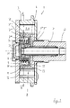
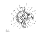
- Fig. 1 and Fig. 2 is a first embodiment of a device 1 for changing the relative angular position of a camshaft 2 relative to a crankshaft of an internal combustion engine shown, so a camshaft adjuster.
- the camshaft actuator 1 has in a known manner a drive element 3 (sometimes referred to as outer rotor or stator) and a rotor 4, which can rotate relative to the stator.
- the rotor is in Fig. 5 shown.
- a fluid channel 7 consists of several fluid channel sections 7 ', 7 ", 7"', 7 "", 7 ""'and 7 “”", as can be seen from the figures. It is essential that in any case a portion of the fluid channel 7 between an end region 8 of the rotor 4 and an insert element 9 is formed, which is attached to the frontal region 8 of the rotor 4.
- the insert element 9 consists in the present case of a rotationally symmetrical component, in particular of a deep-drawn sheet metal part, which has a shape as shown in the radial section Fig. 1 is apparent.
- a ringnutförmige recess 11 is incorporated; the insert element 9 has a radially outer centering section 10, which is designed to match the annular groove-shaped recess 11, so that the insert element 9 can be accurately placed and centered in the frontal region 8 of the rotor 4 and fixed.
- the shape of the insert element 9 makes it possible to provide an annular receptacle (with a substantially rectangular shape in radial section) in which a spring element 14 in the form of a torsion spring is inserted.
- the formation of the individual fluid channel sections results from the synopsis of FIGS. 1 . 2 and 5 ,
- the rotor 4 has a first end-side section 15 and a second end-face section 16 axially offset therefrom (see FIG. Fig. 5 ).
- the rotor 5 has a first axially extending portion 17 and a radially offset thereto second second axially extending portion 18.
- fluid channel sections 7 "" are incorporated into section 15, fluid channel sections 7 "into section 16, fluid channel sections 7 '" into section 17, and fluid channel sections 7 "" into section 18, each having four fluid channel sections of each type distributed over the circumference to supply the corresponding four hydraulic chambers 5, 6 with oil.
- said fluid channel sections are delimited on the front side or radially, so that oil can be transported in them. Oil from a pressure oil source, not shown, can thus reach back into the hydraulic chambers 5 and 6 or from them.
- the entire assembly can be held together by a central screw 20 passing through a bore in the insert element 9.
- the insert element 9 may have a Federeinhfitungsausnaturalung, which may be made by forming.
- a corresponding Federeinhfitungsausnaturalung be provided in the rotor 4.
- both the oil grooves (ie the fluid channel sections mentioned) and the optional spring suspension recess are produced by a sintering process. Subsequent processing becomes superfluous in this case.
Landscapes
- Engineering & Computer Science (AREA)
- Mechanical Engineering (AREA)
- General Engineering & Computer Science (AREA)
- Valve Device For Special Equipments (AREA)
Abstract
Description
- Die Erfindung betrifft eine Vorrichtung zur Veränderung der relativen Winkellage einer Nockenwelle gegenüber einer Kurbelwelle einer Brennkraftmaschine, wobei die Vorrichtung ein von der Kurbelwelle angetriebenes Antriebselement und einen mit der Nockenwelle drehfest verbundenen Rotor aufweist, wobei zwischen dem Antriebselement und dem Rotor mindestens zwei Hydraulikkammern ausgebildet sind, die mit einem Druckfluid beachschlagbar sind, um eine definierte relative Drehstellung zwischen dem Antriebselement und dem Rotor einzustellen, und wobei zwischen einer Druckfluidquelle und den Hydraulikkammern Fluidkanäle ausgebildet sind.
- In Brennkraftmaschinen werden zumeist Nockenwellenverstellvorrichtungen eingesetzt, insbesondere solche, die hydraulisch arbeiten. Beispiele hierfür offenbaren die
DE 198 29 049 A1 und dieUS 5 931 126 . Sofern der Nockenwellenversteller - was typisch ist - hydraulisch arbeitet, weist er ein Flügelrad auf, in dem Flügel eingeformt oder angeordnet sind. Die Flügel befinden sich in Hydraulikkammern, die in einem Antriebselement (auch Außenrotor oder Stator genannt) eingearbeitet sind. Durch entsprechende Beaufschlagung der jeweiligen Seite der Hydraulikkammern mit Hydraulikfluid kann eine Verstellung des Innenrotors (mit der Nockenwelle verbunden) relativ zum Außenrotor zwischen einem "Frühanschlag" und einem "Spätanschlag" erfolgen. Dabei wird der Fluss von Hydrauliköl durch ein elektrisch angesteuertes Wegeventil gesteuert. Die Übertragung der Drehbewegung der Kurbelwelle auf den Außenrotor erfolgt zumeist über ein Zahnrad, mit dem der Außenrotor drehfest verbunden ist. - Zwischen Antriebs- und Abtriebsteil des Nockenwellenverstellers ist häufig eine Feder angeordnet, deren eines Ende direkt oder indirekt an dem Antriebsteil und deren anderes Ende direkt oder indirekt an dem Abtriebsteil abgestützt ist, so dass eine Rückstellung des Antriebs- bzw. Abtriebsteils in eine Grundposition gewährleistet ist. Zur Aufnahme der Feder ist in einem Nockenwellenversteller ein Federaufnahmeraum ausgebildet. Eine solche Lösung zeigt die
DE 10 2008 051 142 A1 . - Dabei ist es gemäß einer Ausgestaltung des Nockenwellenverstellers möglich, einen separaten Aufnahmeraum für die Feder vorzusehen. Der Vorteil dieser Lösung ist eine Trennung des Bereichs der Feder von der Ölzu- und -abführung. Dies erfordert allerdings einen höheren axialen Bauraum und hat somit ein höheres Gewicht des Nockenwellenverstellers zur Folge. Weiterhin sind für die Ölzu- und -abführung Stufenbohrungen nötig, die aufwändig herzustellen sind.
- Eine andere Ausgestaltung des Nockenwellenverstellers sieht vor, dass die Federaufnahmekammer von Öl bei dessen Weg in die Hydraulikkammern durchströmt wird (integrierte Federunterbringung). Nachteilig ist bei dieser Lösung, dass mehr Öl für die Versorgung der Hydraulikkammern nötig ist, da der Federaufnahmeraum erst befüllt werden muss. Weiterhin ist es negativ, dass Schmutz oder Späne, die bei der Montage anfallen können, in den Ölkreislauf gelangen können.
- Um gewichtsreduzierende Maßnahmen am Rotor des Nockenwellenverstellers vorzunehmen, ist die Ölversorgung der beiden Hydraulikkammern im Nockenwellenversteller durch Bohrungen eingeschränkt. Eine Vertiefung, die durch eine der beiden Versorgungsbohrungen gehen würde, ist für das Gewicht des Nockenwellenverstellers von Vorteil, allerdings benötigt das System beim Motorstart durch das so geschaffene Volumen im Rotor mehr Öl, das das System verlangsamen kann, bis die Feder bzw. die Gewichtserleichterungskammer mit Öl befüllt ist.
- Der vorliegenden Erfindung liegt die Aufgabe zugrunde, eine Vorrichtung der eingangs genannten Art so fortzubilden, dass es möglich ist, die genannten Nachteile zu vermeiden. Demgemäß soll ein geringer axialer Bauraum und damit ein geringes Gewicht des Nockenwellenverstellers erreicht werden. Die Fluidkanäle zu den Hydraulikkammern sollen einfach ausgestaltet werden können. Ein besonderes Augenmerk ist auch darauf gerichtet, dass eine Verschmutzung des Ölkreislaufs durch Schmutz oder Spanbildung während der Montage vermieden werden soll.
- Die Lösung dieser Aufgabe durch die Erfindung ist dadurch gekennzeichnet, dass zumindest ein Abschnitt mindestens eines Fluidkanals zwischen einem stirnseitigen Bereich des Rotors und einem Einsatzelement ausgebildet ist, das am stirnseitigen Bereich des Rotors befestigt ist.
- Das Einsatzelement ist bevorzugt als topfförmiges Bauteil ausgebildet.
- Es kann mit einem Zentrierabschnitt in einer ringnutförmigen Ausnehmung am axialen Ende des Rotors angeordnet sein.
- Das Einsatzelement kann eine ringförmige Aufnahme aufweisen. Diese ist bevorzugt dafür vorgesehen, um in ihr ein Federelement, insbesondere eine Torsionsfeder, anzuordnen.
- Mindestens ein sich radial erstreckender Fluidkanalabschnitt kann als Nut in einem ersten stirnseitigen Abschnitt des Rotors ausgebildet sein. Mindestens ein weiterer sich radial erstreckender Fluidkanalabschnitt kann als Nut in einem zweiten stirnseitigen Abschnitt des Rotors ausgebildet sein, der relativ zum ersten stirnseitigen Abschnitt axial versetzt angeordnet ist. Ferner kann mindestens ein sich axial erstreckender Fluidkanalabschnitt als Nut in einem ersten sich in axiale Richtung erstreckenden Abschnitt des Rotors in dessen stirnseitigem Bereich ausgebildet sein. Mindestens ein weiterer sich axial erstreckender Fluidkanalabschnitt kann als Nut in einem zweiten sich in axiale Richtung erstreckenden Abschnitt des Rotors in dessen stirnseitigem Bereich ausgebildet ist, der relativ zum ersten sich in axiale Richtung erstreckenden Abschnitt radial versetzt angeordnet ist.
- Das Einsatzelement ist bevorzugt als dünnwandiges Teil ausgebildet. Es besteht zumeist aus Metall oder aus Kunststoff. Im Falle der Ausbildung als Kunststoffformteil wird in der Regel der Spritzgießprozess eingesetzt. Bei der Ausführung aus Blech können Stanz- und/oder Tiefziehprozesse zur Formung des Einsatzelements eingesetzt werden.
- Durch die Verwendung des Einsatzelements, insbesondere als geformtes Blech, nutzt man den im Rotor geschaffenen Freiraum, um die Feder zu platzieren und zusätzlich die Ölversorgung direkt über Nuten im Rotor in die jeweilige Hydraulikkammer des Nockenwellenverstellers zu transportieren, ohne den Freiraum mit Öl befüllen zu müssen.
- Weiterhin werden Schmutz oder Späne, die bei der Montage des Nockenwellenverstellers entstehen, nicht dem Ölkreislauf zugeführt, sondern durch das Einsatzelement abgehalten.
- Der Rotor ist dabei bevorzugt mit einem vertieften, ununterbrochenen Absatz versehen (ringnutförmige Ausnehmung). Dadurch lässt sich das Einsatzelement, das ein Schmutzblech bildet, plan in den Rotor einbauen. Hierdurch ist eine kostengünstige und hochgenaue Bearbeitung (z. B. durch Schleifen) der Rotorstirnfläche möglich. Die somit entstandenen Ringflächen dienen zur Abdichtung des Ölflusses. Die Ölleckage wird durch Reduktion der Spaltmaße oder durch den Einsatz von Dichtelementen reduziert.
- Durch eine Änderung der Geometrie am Einsatzelement ist eine vielfältige Variantenmöglichkeit gegeben; hiermit ist auch eine Verwechslungsgefahr bei der Montage nicht gegeben.
- Die erwähnte Feder ist nicht zwingend; auf sie kann bei entsprechenden Bauformen auch verzichtet werden. Hierdurch ergeben sich zusätzliche Gewichtsvorteile gegenüber herkömmlichen Gewichtserleichterungsmaßnahmen.
- Insgesamt ergibt sich somit durch den Einsatz des Einsatzelements beim Montageprozess keine Gefahr einer Verschmutzung des Ölkreislaufes. Eine ununterbrochene Ölversorgung ist auch bei Vorliegen der innenliegenden Feder gegeben.
- Das Gewicht des Nockenwellenverstellers kann so minimiert werden.
- Beim Motorstart ist weniger Öl notwendig.
- In den Zeichnungen sind Ausführungsbeispiele der Erfindung dargestellt. Es zeigen:
- Fig. 1
- in einer Radialschnittdarstellung einen Nockenwellenversteller einer Brennkraftmaschine gemäß einer ersten Ausführungsform der Erfindung, und zwar den Schnitt C-D gemäß
Fig. 2 , - Fig. 2
- den Schnitt A-B gemäß
Fig. 1 durch den Nockenwellenversteller, - Fig. 3
- in einer Radialschnittdarstellung den Nockenwellenversteller gemäß einer zweiten Ausführungsform der Erfindung, und zwar den Schnitt C-D gemäß
Fig. 4 , - Fig. 4
- den Schnitt A-B gemäß
Fig. 3 durch den Nockenwellenversteller und - Fig. 5
- in perspektivischer Darstellung den Rotor des Nockenwellenverstellers.
- In
Fig. 1 undFig. 2 ist eine erste Ausführungsform einer Vorrichtung 1 zur Veränderung der relativen Winkellage einer Nockenwelle 2 gegenüber einer Kurbelwelle einer Brennkraftmaschine dargestellt, also ein Nockenwellenversteller. Der Nockenwellensteller 1 hat dabei in bekannter Weise ein Antriebselement 3 (gelegentlich als Außenrotor oder Stator bezeichnet) und einen Rotor 4, der sich relativ zum Stator verdrehen kann. Der Rotor ist inFig. 5 dargestellt. Zu Details wird ausdrücklich auf die oben genannten Druckschriften hingewiesen, wo auch Ausführungen zur generellen Betriebsweise des Nockenwellenverstellers zu finden sind. - Um eine relativ Verdrehung zwischen Antriebselement 3 und Rotor 4 zu bewerkstelligen, sind mehrere Hydraulikkammern zwischen Antriebselement und Rotor aus ausgebildet, die durch am Rotor 4 angeordnete Flügel 19 unterteilt sind, so dass sich Hydraulikkammern 5 und 6 bilden. In Abhängigkeit von der Beschickung der Hydraulikkammern 5 und 6 erfolgt die relative Verdrehung zwischen Antriebselement 3 und Rotor 4.
- Das hierfür benötigte Hydrauliköl wird über Fluidkanäle 7 der jeweiligen Kammer 5, 6 zugeführt. Ein Fluidkanal 7 besteht aus mehreren Fluidkanalabschnitten 7', 7", 7"', 7"", 7""' und 7""", wie es aus den Figuren hervorgeht. Wesentlich ist, dass jedenfalls ein Abschnitt des Fluidkanals 7 zwischen einem stirnseitigen Bereich 8 des Rotors 4 und einem Einsatzelement 9 ausgebildet ist, das am stirnseitigen Bereich 8 des Rotors 4 befestigt ist.
- Das Einsatzelement 9 besteht vorliegend aus einem rotationssymmetrischen Bauteil, insbesondere aus einem tiefgezogenen Blechteil, das eine Form aufweist, wie es aus dem Radialschnitt gemäß
Fig. 1 ersichtlich ist. Am axialen Ende 12 des Rotors 4 ist eine ringnutförmige Ausnehmung 11 eingearbeitet; das Einsatzelement 9 weist einen radial außenliegenden Zentrierabschnitt 10 auf, der passend zu der ringnutförmigen Ausnehmung 11 ausgeführt ist, so dass das Einsatzelement 9 passgenau und zentriert im stirnseitigen Bereich 8 des Rotors 4 platziert und befestigt werden kann. - Die Ausformung des Einsatzelements 9 ermöglicht es, dass eine ringförmige Aufnahme (mit im Radialschnitt im wesentlichen rechteckiger Form) geschaffen wird, in der ein Federelement 14 in Form einer Torsionsfeder eingesetzt ist.
- Die Ausbildung der einzelnen Fluidkanalabschnitte ergibt sich aus der Zusammenschau der
Figuren 1 ,2 und5 . Der Rotor 4 weist einen ersten stirnseitigen Abschnitt 15 und einen hierzu axial versetzten zweiten stirnseitigen Abschnitt 16 auf (s.Fig. 5 ). Gleichermaßen weist der Rotor 5 einen ersten sich axial erstreckenden Abschnitt 17 sowie einen radial hierzu versetzten zweiten sich axial erstreckenden Abschnitt 18 auf. - Wie in
Fig. 5 am besten zu erkennen ist, sind sich radial oder sich axial erstreckende Nuten in die Abschnitte 15, 16, 17 und 18 eingearbeitet, die die Fluidkanalabschnitte bilden. Konkret sind Fluidkanalabschnitte 7"" in den Abschnitt 15, Fluidkanalabschnitte 7" in den Abschnitt 16, Fluidkanalabschnitte 7'" in den Abschnitt 17 und Fluidkanalabschnitte 7"'" in den Abschnitt 18 eingearbeitet, und zwar jeweils vier Fluidkanalabschnitt jeder der genannten Art, gleichmäßig über dem Umfang verteilt, um die entsprechenden vier Hydraulikkammern 5, 6 mit Öl zu versorgen. - Wird das Einsatzelement 9 montiert, werden die genannten Fluidkanalabschnitte stirnseitig bzw. radial begrenzt, so dass in ihnen Öl transportiert werden kann. Öl von einer nicht dargestellten Druckölquelle kann somit bis in die Hydraulikkammern 5 bzw. 6 oder aus ihnen zurück gelangen.
- Die gesamte Anordnung kann durch eine Zentralschraube 20 zusammengehalten werden, die eine Bohrung im Einsatzelement 9 durchsetzt.
- Für die Festlegung des Federelements 14 kann das Einsatzelement 9 eine Federeinhängungsausnehmung aufweisen, die mittels Umformung hergestellt sein kann. Gegebenenfalls kann auch im Rotor 4 eine entsprechende Federeinhängungsausnehmung vorgesehen werden.
- Fertigungstechnisch vorteilhaft kann es sein, wenn mittels eines Sinterverfahrens die benötigten Nuten und ggf. Ausnehmungen hergestellt werden. Hiernach werden also durch ein Sinterverfahren sowohl die Ölnuten (d. h. die genannten Fluidkanalabschnitte) als auch die optionale Federeinhängungsausnehmung hergestellt. Eine nachträgliche Bearbeitung wird in diesem Falle überflüssig.
- In den
Figuren 3 und4 ist eine Alternative dargestellt, die sich im wesentlichen nur dadurch unterscheidet, dass kein Federelement 14 vorhanden ist. Dennoch ist das Einsatzelement 9 gleich ausgebildet. Die also weiter vorhandene ringförmige Aufnahme 13 erfüllt die Funktion, dass der mit Öl zu füllende Raum gering gehalten wird. -
- 1
- Vorrichtung zur Veränderung der relativen Winkellage (Nockenwellenversteller)
- 2
- Nockenwelle
- 3
- Antriebselement
- 4
- Rotor
- 5
- Hydraulikkammer
- 6
- Hydraulikkammer
- 7
- Fluidkanal
- 7'
- Fluidkanalabschnitt
- 7"
- Fluidkanalabschnitt
- 7'"
- Fluidkanalabschnitt
- 7""
- Fluidkanalabschnitt
- 7"'"
- Fluidkanalabschnitt
- 7"""
- Fluidkanalabschnitt
- 8
- stirnseitiger Bereich des Rotors
- 9
- Einsatzelement
- 10
- Zentrierabschnitt
- 11
- ringnutförmige Ausnehmung
- 12
- axiales Ende des Rotors
- 13
- ringförmige Aufnahme
- 14
- Federelement
- 15
- erster stirnseitiger Abschnitt des Rotors
- 16
- zweiter stirnseitiger Abschnitt des Rotors
- 17
- erster sich axial erstreckender Abschnitt des Rotors
- 18
- zweiter sich axial erstreckender Abschnitt des Rotors
- 19
- Flügel
- 20
- Zentralschraube
Claims (10)
- Vorrichtung (1) zur Veränderung der relativen Winkellage einer Nockenwelle (2) gegenüber einer Kurbelwelle einer Brennkraftmaschine, wobei die Vorrichtung (1) ein von der Kurbelwelle angetriebenes Antriebselement (3) und einen mit der Nockenwelle (2) drehfest verbundenen Rotor (4) aufweist, wobei zwischen dem Antriebselement (3) und dem Rotor (4) mindestens zwei Hydraulikkammern (5, 6) ausgebildet sind, die mit einem Druckfluid beachschlagbar sind, um eine definierte relative Drehstellung zwischen dem Antriebselement (3) und dem Rotor (4) einzustellen, und wobei zwischen einer Druckfluidquelle und den Hydraulikkammern (5, 6) Fluidkanäle (7) ausgebildet sind, dadurch gekennzeichnet, dass zumindest ein Abschnitt mindestens eines Fluidkanals (7) zwischen einem stirnseitigen Bereich (8) des Rotors (4) und einem Einsatzelement (9) ausgebildet ist, das am stirnseitigen Bereich (8) des Rotors (4) befestigt ist.
- Vorrichtung nach Anspruch 1, dadurch gekennzeichnet, dass das Einsatzelement (9) als topfförmiges Bauteil ausgebildet ist.
- Vorrichtung nach Anspruch 1, dadurch gekennzeichnet, dass das Einsatzelement (9) mit einem Zentrierabschnitt (10) in einer ringnutförmigen Ausnehmung (11) am axialen Ende (12) des Rotors (4) angeordnet ist.
- Vorrichtung nach Anspruch 1, dadurch gekennzeichnet, dass das Einsatzelement (9) eine ringförmige Aufnahme (13) aufweist.
- Vorrichtung nach Anspruch 4, dadurch gekennzeichnet, dass in der ringförmigen Aufnahme (13) ein Federelement (14), insbesondere eine Torsionsfeder, angeordnet ist.
- Vorrichtung nach Anspruch 1, dadurch gekennzeichnet, dass mindestens ein sich radial erstreckender Fluidkanalabschnitt (7"") als Nut in einem ersten stirnseitigen Abschnitt (15) des Rotors (4) ausgebildet ist.
- Vorrichtung nach Anspruch 6, dadurch gekennzeichnet, dass mindestens ein weiterer sich radial erstreckender Fluidkanalabschnitt (7") als Nut in einem zweiten stirnseitigen Abschnitt (16) des Rotors (4) ausgebildet ist, der relativ zum ersten stirnseitigen Abschnitt (15) axial versetzt angeordnet ist.
- Vorrichtung nach Anspruch 1, dadurch gekennzeichnet, dass mindestens ein sich axial erstreckender Fluidkanalabschnitt (7'") als Nut in einem ersten sich in axiale Richtung erstreckenden Abschnitt (17) des Rotors (4) in dessen stirnseitigem Bereich (8) ausgebildet ist.
- Vorrichtung nach Anspruch 8, dadurch gekennzeichnet, dass mindestens ein sich axial erstreckender Fluidkanalabschnitt (7""') als Nut in einem zweiten sich in axiale Richtung erstreckenden Abschnitt (18) des Rotors (4) in dessen stirnseitigem Bereich (8) ausgebildet ist, der relativ zum ersten sich in axiale Richtung erstreckenden Abschnitt (17) radial versetzt angeordnet ist.
- Vorrichtung nach Anspruch 1, dadurch gekennzeichnet, dass das Einsatzelement (9) als dünnwandiges Teil ausgebildet ist, das aus Metall oder Kunststoff besteht.
Applications Claiming Priority (1)
| Application Number | Priority Date | Filing Date | Title |
|---|---|---|---|
| DE201110003053 DE102011003053A1 (de) | 2011-01-24 | 2011-01-24 | Vorrichtung zur Veränderung der relativen Winkellage einer Nockenwelle gegenüber einer Kurbelwelle einer Brennkraftmaschine |
Publications (2)
| Publication Number | Publication Date |
|---|---|
| EP2479387A1 true EP2479387A1 (de) | 2012-07-25 |
| EP2479387B1 EP2479387B1 (de) | 2013-06-05 |
Family
ID=45440096
Family Applications (1)
| Application Number | Title | Priority Date | Filing Date |
|---|---|---|---|
| EP20110189676 Not-in-force EP2479387B1 (de) | 2011-01-24 | 2011-11-18 | Vorrichtung zur Veränderung der relativen Winkellage einer Nockenwelle gegenüber einer Kurbelwelle einer Brennkraftmaschine |
Country Status (2)
| Country | Link |
|---|---|
| EP (1) | EP2479387B1 (de) |
| DE (1) | DE102011003053A1 (de) |
Cited By (1)
| Publication number | Priority date | Publication date | Assignee | Title |
|---|---|---|---|---|
| DE102016217968A1 (de) | 2016-09-20 | 2018-03-22 | Schaeffler Technologies AG & Co. KG | Zentrierende Verbindung eines Triggerrades mit einem Rotor in einem Nockenwellenversteller |
Citations (9)
| Publication number | Priority date | Publication date | Assignee | Title |
|---|---|---|---|---|
| DE19742947A1 (de) * | 1996-10-02 | 1998-04-16 | Denso Corp | Drehphaseneinstellvorrichtung mit einem Anschlagkolben |
| JPH10159518A (ja) * | 1996-12-02 | 1998-06-16 | Toyota Motor Corp | 内燃機関のバルブタイミング制御装置 |
| DE19829049A1 (de) | 1997-06-30 | 1999-01-07 | Aisin Seiki | Ventilsteuerungsvorrichtung |
| US5931126A (en) | 1995-11-30 | 1999-08-03 | Aisin Seiki Kabushiki Kaisha | Valve timing control device |
| US20020038641A1 (en) * | 2000-10-03 | 2002-04-04 | Kazutoshi Iwasaki | Valve timing adjusting device |
| DE102005041393A1 (de) * | 2005-09-01 | 2007-03-08 | Schaeffler Kg | Steuerventil für eine Vorrichtung zur Veränderung der Steuerzeiten einer Brennkraftmaschine |
| WO2008067935A2 (de) * | 2006-12-04 | 2008-06-12 | Daimler Ag | Verstelleinrichtung |
| DE102008051142A1 (de) | 2008-10-09 | 2010-04-15 | Schaeffler Kg | Nockenwellenversteller |
| DE102009041768A1 (de) * | 2008-10-09 | 2010-04-22 | Schaeffler Kg | Nockenwellenversteller für eine konzentrische Nockenwelle |
-
2011
- 2011-01-24 DE DE201110003053 patent/DE102011003053A1/de not_active Withdrawn
- 2011-11-18 EP EP20110189676 patent/EP2479387B1/de not_active Not-in-force
Patent Citations (9)
| Publication number | Priority date | Publication date | Assignee | Title |
|---|---|---|---|---|
| US5931126A (en) | 1995-11-30 | 1999-08-03 | Aisin Seiki Kabushiki Kaisha | Valve timing control device |
| DE19742947A1 (de) * | 1996-10-02 | 1998-04-16 | Denso Corp | Drehphaseneinstellvorrichtung mit einem Anschlagkolben |
| JPH10159518A (ja) * | 1996-12-02 | 1998-06-16 | Toyota Motor Corp | 内燃機関のバルブタイミング制御装置 |
| DE19829049A1 (de) | 1997-06-30 | 1999-01-07 | Aisin Seiki | Ventilsteuerungsvorrichtung |
| US20020038641A1 (en) * | 2000-10-03 | 2002-04-04 | Kazutoshi Iwasaki | Valve timing adjusting device |
| DE102005041393A1 (de) * | 2005-09-01 | 2007-03-08 | Schaeffler Kg | Steuerventil für eine Vorrichtung zur Veränderung der Steuerzeiten einer Brennkraftmaschine |
| WO2008067935A2 (de) * | 2006-12-04 | 2008-06-12 | Daimler Ag | Verstelleinrichtung |
| DE102008051142A1 (de) | 2008-10-09 | 2010-04-15 | Schaeffler Kg | Nockenwellenversteller |
| DE102009041768A1 (de) * | 2008-10-09 | 2010-04-22 | Schaeffler Kg | Nockenwellenversteller für eine konzentrische Nockenwelle |
Cited By (1)
| Publication number | Priority date | Publication date | Assignee | Title |
|---|---|---|---|---|
| DE102016217968A1 (de) | 2016-09-20 | 2018-03-22 | Schaeffler Technologies AG & Co. KG | Zentrierende Verbindung eines Triggerrades mit einem Rotor in einem Nockenwellenversteller |
Also Published As
| Publication number | Publication date |
|---|---|
| DE102011003053A1 (de) | 2012-07-26 |
| EP2479387B1 (de) | 2013-06-05 |
Similar Documents
| Publication | Publication Date | Title |
|---|---|---|
| DE19817319C2 (de) | Nockenwellenversteller für Brennkraftmaschinen | |
| EP1731722B1 (de) | Nockenwellenversteller mit Schwenkmotorrotor mit verringerter Leckage | |
| DE102010026853B4 (de) | Steuerventil zur Steuerung von Druckmittelströmen eines Nockenwellenverstellers | |
| DE102010050606A1 (de) | Rotor für einen Nockenwellenversteller sowie Nockenwellenversteller | |
| EP1752691B1 (de) | Steuerventil und Verfahren zur Herstellung desselben | |
| EP2870327B1 (de) | Schwenkmotorversteller mit einem hydraulikventil | |
| DE102009024026A1 (de) | Steuerventil zum Steuern von Druckmittelströmen mit integriertem Rückschlagventil | |
| DE10300974A1 (de) | Proportionalmagnetventil einer Nockenwellenverstelleinrichtung für Kraftfahrzeuge | |
| DE102012213176A1 (de) | Hydraulischer Nockenwellenversteller | |
| DE102005028757A1 (de) | Steuerventil für eine Vorrichtung zur variablen Einstellung der Steuerzeiten von Gaswechselventilen einer Brennkraftmaschine | |
| WO2008135420A1 (de) | Nockenwellenversteller für eine brennkraftmaschine mit verbesserter ausführung der druckräume | |
| WO2011098331A1 (de) | Flügelrad einer vorrichtung zur variablen einstellung der steuerzeiten von gaswechselventilen einer brennkraftmaschine | |
| EP2539555B1 (de) | Vorrichtung zur variablen einstellung der steuerzeiten von gaswechselventilen einer brennkraftmaschine | |
| WO2001031174A1 (de) | Vorrichtung zur hydraulischen drehwinkelverstellung einer welle relativ zu einem antriebsrad | |
| EP2479387B1 (de) | Vorrichtung zur Veränderung der relativen Winkellage einer Nockenwelle gegenüber einer Kurbelwelle einer Brennkraftmaschine | |
| DE102021119442A1 (de) | Verfahren zur Herstellung eines Nockenwellenverstellers | |
| DE102010013777A1 (de) | Zentralventil | |
| EP2582929B1 (de) | Rotor für einen nockenwellenversteller und nockenwellenversteller | |
| WO2006108494A1 (de) | Vorrichtung zur variablen einstellung der steuerzeiten von gaswechselventilen einer brennkraftmaschine | |
| DE102014206620A1 (de) | Nockenwellenversteller mit Abflussventil | |
| DE102010013928A1 (de) | Rotoreinheit für einen Nockenwellenversteller sowie Nockenwellenverstellsystem | |
| DE102018102440A1 (de) | Vorrichtung zur variablen Ventilzeitsteuerung des Freilaufkupplungstyps und Motorsystem mit derselben | |
| DE102012208808A1 (de) | Steuerventil zur Steuerung von Druckmittelströmen eines Nockenwellenverstellers | |
| DE102021119625A1 (de) | Verfahren zur Herstellung eines Nockenwellenverstellers | |
| DE102016220830A1 (de) | Rotor mit durch je zwei Platten ausgeformten Fluidleitkanal für einen Nockenwellenversteller und Nockenwellenversteller |
Legal Events
| Date | Code | Title | Description |
|---|---|---|---|
| PUAI | Public reference made under article 153(3) epc to a published international application that has entered the european phase |
Free format text: ORIGINAL CODE: 0009012 |
|
| 17P | Request for examination filed |
Effective date: 20111118 |
|
| AK | Designated contracting states |
Kind code of ref document: A1 Designated state(s): AL AT BE BG CH CY CZ DE DK EE ES FI FR GB GR HR HU IE IS IT LI LT LU LV MC MK MT NL NO PL PT RO RS SE SI SK SM TR |
|
| AX | Request for extension of the european patent |
Extension state: BA ME |
|
| 17Q | First examination report despatched |
Effective date: 20120928 |
|
| GRAP | Despatch of communication of intention to grant a patent |
Free format text: ORIGINAL CODE: EPIDOSNIGR1 |
|
| GRAS | Grant fee paid |
Free format text: ORIGINAL CODE: EPIDOSNIGR3 |
|
| GRAA | (expected) grant |
Free format text: ORIGINAL CODE: 0009210 |
|
| AK | Designated contracting states |
Kind code of ref document: B1 Designated state(s): AL AT BE BG CH CY CZ DE DK EE ES FI FR GB GR HR HU IE IS IT LI LT LU LV MC MK MT NL NO PL PT RO RS SE SI SK SM TR |
|
| REG | Reference to a national code |
Ref country code: GB Ref legal event code: FG4D Free format text: NOT ENGLISH |
|
| REG | Reference to a national code |
Ref country code: CH Ref legal event code: EP |
|
| REG | Reference to a national code |
Ref country code: AT Ref legal event code: REF Ref document number: 615792 Country of ref document: AT Kind code of ref document: T Effective date: 20130615 |
|
| REG | Reference to a national code |
Ref country code: IE Ref legal event code: FG4D Free format text: LANGUAGE OF EP DOCUMENT: GERMAN |
|
| REG | Reference to a national code |
Ref country code: DE Ref legal event code: R096 Ref document number: 502011000863 Country of ref document: DE Effective date: 20130801 |
|
| PG25 | Lapsed in a contracting state [announced via postgrant information from national office to epo] |
Ref country code: SI Free format text: LAPSE BECAUSE OF FAILURE TO SUBMIT A TRANSLATION OF THE DESCRIPTION OR TO PAY THE FEE WITHIN THE PRESCRIBED TIME-LIMIT Effective date: 20130605 Ref country code: NO Free format text: LAPSE BECAUSE OF FAILURE TO SUBMIT A TRANSLATION OF THE DESCRIPTION OR TO PAY THE FEE WITHIN THE PRESCRIBED TIME-LIMIT Effective date: 20130905 Ref country code: FI Free format text: LAPSE BECAUSE OF FAILURE TO SUBMIT A TRANSLATION OF THE DESCRIPTION OR TO PAY THE FEE WITHIN THE PRESCRIBED TIME-LIMIT Effective date: 20130605 Ref country code: GR Free format text: LAPSE BECAUSE OF FAILURE TO SUBMIT A TRANSLATION OF THE DESCRIPTION OR TO PAY THE FEE WITHIN THE PRESCRIBED TIME-LIMIT Effective date: 20130906 Ref country code: ES Free format text: LAPSE BECAUSE OF FAILURE TO SUBMIT A TRANSLATION OF THE DESCRIPTION OR TO PAY THE FEE WITHIN THE PRESCRIBED TIME-LIMIT Effective date: 20130916 Ref country code: LT Free format text: LAPSE BECAUSE OF FAILURE TO SUBMIT A TRANSLATION OF THE DESCRIPTION OR TO PAY THE FEE WITHIN THE PRESCRIBED TIME-LIMIT Effective date: 20130605 Ref country code: SE Free format text: LAPSE BECAUSE OF FAILURE TO SUBMIT A TRANSLATION OF THE DESCRIPTION OR TO PAY THE FEE WITHIN THE PRESCRIBED TIME-LIMIT Effective date: 20130605 |
|
| REG | Reference to a national code |
Ref country code: NL Ref legal event code: VDEP Effective date: 20130605 |
|
| REG | Reference to a national code |
Ref country code: LT Ref legal event code: MG4D |
|
| PG25 | Lapsed in a contracting state [announced via postgrant information from national office to epo] |
Ref country code: BG Free format text: LAPSE BECAUSE OF FAILURE TO SUBMIT A TRANSLATION OF THE DESCRIPTION OR TO PAY THE FEE WITHIN THE PRESCRIBED TIME-LIMIT Effective date: 20130905 Ref country code: RS Free format text: LAPSE BECAUSE OF FAILURE TO SUBMIT A TRANSLATION OF THE DESCRIPTION OR TO PAY THE FEE WITHIN THE PRESCRIBED TIME-LIMIT Effective date: 20130605 Ref country code: HR Free format text: LAPSE BECAUSE OF FAILURE TO SUBMIT A TRANSLATION OF THE DESCRIPTION OR TO PAY THE FEE WITHIN THE PRESCRIBED TIME-LIMIT Effective date: 20130605 |
|
| PG25 | Lapsed in a contracting state [announced via postgrant information from national office to epo] |
Ref country code: LV Free format text: LAPSE BECAUSE OF FAILURE TO SUBMIT A TRANSLATION OF THE DESCRIPTION OR TO PAY THE FEE WITHIN THE PRESCRIBED TIME-LIMIT Effective date: 20130605 |
|
| PG25 | Lapsed in a contracting state [announced via postgrant information from national office to epo] |
Ref country code: SK Free format text: LAPSE BECAUSE OF FAILURE TO SUBMIT A TRANSLATION OF THE DESCRIPTION OR TO PAY THE FEE WITHIN THE PRESCRIBED TIME-LIMIT Effective date: 20130605 Ref country code: IS Free format text: LAPSE BECAUSE OF FAILURE TO SUBMIT A TRANSLATION OF THE DESCRIPTION OR TO PAY THE FEE WITHIN THE PRESCRIBED TIME-LIMIT Effective date: 20131005 Ref country code: PT Free format text: LAPSE BECAUSE OF FAILURE TO SUBMIT A TRANSLATION OF THE DESCRIPTION OR TO PAY THE FEE WITHIN THE PRESCRIBED TIME-LIMIT Effective date: 20131007 Ref country code: EE Free format text: LAPSE BECAUSE OF FAILURE TO SUBMIT A TRANSLATION OF THE DESCRIPTION OR TO PAY THE FEE WITHIN THE PRESCRIBED TIME-LIMIT Effective date: 20130605 Ref country code: CZ Free format text: LAPSE BECAUSE OF FAILURE TO SUBMIT A TRANSLATION OF THE DESCRIPTION OR TO PAY THE FEE WITHIN THE PRESCRIBED TIME-LIMIT Effective date: 20130605 |
|
| PG25 | Lapsed in a contracting state [announced via postgrant information from national office to epo] |
Ref country code: PL Free format text: LAPSE BECAUSE OF FAILURE TO SUBMIT A TRANSLATION OF THE DESCRIPTION OR TO PAY THE FEE WITHIN THE PRESCRIBED TIME-LIMIT Effective date: 20130605 Ref country code: RO Free format text: LAPSE BECAUSE OF FAILURE TO SUBMIT A TRANSLATION OF THE DESCRIPTION OR TO PAY THE FEE WITHIN THE PRESCRIBED TIME-LIMIT Effective date: 20130605 Ref country code: NL Free format text: LAPSE BECAUSE OF FAILURE TO SUBMIT A TRANSLATION OF THE DESCRIPTION OR TO PAY THE FEE WITHIN THE PRESCRIBED TIME-LIMIT Effective date: 20130605 |
|
| RAP2 | Party data changed (patent owner data changed or rights of a patent transferred) |
Owner name: SCHAEFFLER TECHNOLOGIES GMBH & CO. KG |
|
| REG | Reference to a national code |
Ref country code: DE Ref legal event code: R081 Ref document number: 502011000863 Country of ref document: DE Owner name: SCHAEFFLER TECHNOLOGIES GMBH & CO. KG, DE Free format text: FORMER OWNER: SCHAEFFLER TECHNOLOGIES AG & CO. KG, 91074 HERZOGENAURACH, DE Effective date: 20140218 Ref country code: DE Ref legal event code: R081 Ref document number: 502011000863 Country of ref document: DE Owner name: SCHAEFFLER TECHNOLOGIES AG & CO. KG, DE Free format text: FORMER OWNER: SCHAEFFLER TECHNOLOGIES AG & CO. KG, 91074 HERZOGENAURACH, DE Effective date: 20140218 |
|
| PLBE | No opposition filed within time limit |
Free format text: ORIGINAL CODE: 0009261 |
|
| STAA | Information on the status of an ep patent application or granted ep patent |
Free format text: STATUS: NO OPPOSITION FILED WITHIN TIME LIMIT |
|
| PG25 | Lapsed in a contracting state [announced via postgrant information from national office to epo] |
Ref country code: DK Free format text: LAPSE BECAUSE OF FAILURE TO SUBMIT A TRANSLATION OF THE DESCRIPTION OR TO PAY THE FEE WITHIN THE PRESCRIBED TIME-LIMIT Effective date: 20130605 |
|
| 26N | No opposition filed |
Effective date: 20140306 |
|
| PG25 | Lapsed in a contracting state [announced via postgrant information from national office to epo] |
Ref country code: IT Free format text: LAPSE BECAUSE OF FAILURE TO SUBMIT A TRANSLATION OF THE DESCRIPTION OR TO PAY THE FEE WITHIN THE PRESCRIBED TIME-LIMIT Effective date: 20130605 |
|
| BERE | Be: lapsed |
Owner name: SCHAEFFLER TECHNOLOGIES A.G. & CO. KG Effective date: 20131130 |
|
| REG | Reference to a national code |
Ref country code: DE Ref legal event code: R097 Ref document number: 502011000863 Country of ref document: DE Effective date: 20140306 |
|
| REG | Reference to a national code |
Ref country code: HU Ref legal event code: AG4A Ref document number: E019704 Country of ref document: HU |
|
| PG25 | Lapsed in a contracting state [announced via postgrant information from national office to epo] |
Ref country code: MC Free format text: LAPSE BECAUSE OF FAILURE TO SUBMIT A TRANSLATION OF THE DESCRIPTION OR TO PAY THE FEE WITHIN THE PRESCRIBED TIME-LIMIT Effective date: 20130605 |
|
| REG | Reference to a national code |
Ref country code: FR Ref legal event code: ST Effective date: 20140731 |
|
| REG | Reference to a national code |
Ref country code: IE Ref legal event code: MM4A |
|
| PG25 | Lapsed in a contracting state [announced via postgrant information from national office to epo] |
Ref country code: BE Free format text: LAPSE BECAUSE OF NON-PAYMENT OF DUE FEES Effective date: 20131130 |
|
| PG25 | Lapsed in a contracting state [announced via postgrant information from national office to epo] |
Ref country code: IE Free format text: LAPSE BECAUSE OF NON-PAYMENT OF DUE FEES Effective date: 20131118 |
|
| PG25 | Lapsed in a contracting state [announced via postgrant information from national office to epo] |
Ref country code: FR Free format text: LAPSE BECAUSE OF NON-PAYMENT OF DUE FEES Effective date: 20131202 |
|
| REG | Reference to a national code |
Ref country code: HU Ref legal event code: FH1C Free format text: FORMER REPRESENTATIVE(S): MESZAROSNE DONUSZ KATALIN, SBGK SZABADALMI UEGYVIVOEI IRODA, HU Representative=s name: SBGK SZABADALMI UEGYVIVOEI IRODA, HU Ref country code: HU Ref legal event code: GB9C Owner name: SCHAEFFLER TECHNOLOGIES GMBH & CO. KG, DE Free format text: FORMER OWNER(S): SCHAEFFLER TECHNOLOGIES AG & CO. KG, DE |
|
| REG | Reference to a national code |
Ref country code: DE Ref legal event code: R081 Ref document number: 502011000863 Country of ref document: DE Owner name: SCHAEFFLER TECHNOLOGIES AG & CO. KG, DE Free format text: FORMER OWNER: SCHAEFFLER TECHNOLOGIES GMBH & CO. KG, 91074 HERZOGENAURACH, DE Effective date: 20150407 |
|
| PG25 | Lapsed in a contracting state [announced via postgrant information from national office to epo] |
Ref country code: SM Free format text: LAPSE BECAUSE OF FAILURE TO SUBMIT A TRANSLATION OF THE DESCRIPTION OR TO PAY THE FEE WITHIN THE PRESCRIBED TIME-LIMIT Effective date: 20130605 |
|
| REG | Reference to a national code |
Ref country code: HU Ref legal event code: FH1C Free format text: FORMER REPRESENTATIVE(S): SBGK SZABADALMI UEGYVIVOEI IRODA, HU Representative=s name: SBGK SZABADALMI UEGYVIVOEI IRODA, HU Ref country code: HU Ref legal event code: GB9C Owner name: SCHAEFFLER TECHNOLOGIES AG & CO. KG, DE Free format text: FORMER OWNER(S): SCHAEFFLER TECHNOLOGIES AG & CO. KG, DE; SCHAEFFLER TECHNOLOGIES GMBH & CO. KG, DE |
|
| PG25 | Lapsed in a contracting state [announced via postgrant information from national office to epo] |
Ref country code: CY Free format text: LAPSE BECAUSE OF FAILURE TO SUBMIT A TRANSLATION OF THE DESCRIPTION OR TO PAY THE FEE WITHIN THE PRESCRIBED TIME-LIMIT Effective date: 20130605 |
|
| REG | Reference to a national code |
Ref country code: CH Ref legal event code: PL |
|
| PG25 | Lapsed in a contracting state [announced via postgrant information from national office to epo] |
Ref country code: CH Free format text: LAPSE BECAUSE OF NON-PAYMENT OF DUE FEES Effective date: 20141130 Ref country code: MK Free format text: LAPSE BECAUSE OF FAILURE TO SUBMIT A TRANSLATION OF THE DESCRIPTION OR TO PAY THE FEE WITHIN THE PRESCRIBED TIME-LIMIT Effective date: 20130605 Ref country code: LU Free format text: LAPSE BECAUSE OF NON-PAYMENT OF DUE FEES Effective date: 20131118 Ref country code: LI Free format text: LAPSE BECAUSE OF NON-PAYMENT OF DUE FEES Effective date: 20141130 |
|
| PG25 | Lapsed in a contracting state [announced via postgrant information from national office to epo] |
Ref country code: MT Free format text: LAPSE BECAUSE OF FAILURE TO SUBMIT A TRANSLATION OF THE DESCRIPTION OR TO PAY THE FEE WITHIN THE PRESCRIBED TIME-LIMIT Effective date: 20130605 |
|
| GBPC | Gb: european patent ceased through non-payment of renewal fee |
Effective date: 20151118 |
|
| PG25 | Lapsed in a contracting state [announced via postgrant information from national office to epo] |
Ref country code: TR Free format text: LAPSE BECAUSE OF FAILURE TO SUBMIT A TRANSLATION OF THE DESCRIPTION OR TO PAY THE FEE WITHIN THE PRESCRIBED TIME-LIMIT Effective date: 20130605 |
|
| PG25 | Lapsed in a contracting state [announced via postgrant information from national office to epo] |
Ref country code: GB Free format text: LAPSE BECAUSE OF NON-PAYMENT OF DUE FEES Effective date: 20151118 |
|
| REG | Reference to a national code |
Ref country code: AT Ref legal event code: MM01 Ref document number: 615792 Country of ref document: AT Kind code of ref document: T Effective date: 20161118 |
|
| PG25 | Lapsed in a contracting state [announced via postgrant information from national office to epo] |
Ref country code: AT Free format text: LAPSE BECAUSE OF NON-PAYMENT OF DUE FEES Effective date: 20161118 |
|
| PG25 | Lapsed in a contracting state [announced via postgrant information from national office to epo] |
Ref country code: AL Free format text: LAPSE BECAUSE OF FAILURE TO SUBMIT A TRANSLATION OF THE DESCRIPTION OR TO PAY THE FEE WITHIN THE PRESCRIBED TIME-LIMIT Effective date: 20130605 |
|
| PGFP | Annual fee paid to national office [announced via postgrant information from national office to epo] |
Ref country code: HU Payment date: 20211117 Year of fee payment: 11 |
|
| PGFP | Annual fee paid to national office [announced via postgrant information from national office to epo] |
Ref country code: DE Payment date: 20220119 Year of fee payment: 11 |
|
| REG | Reference to a national code |
Ref country code: DE Ref legal event code: R119 Ref document number: 502011000863 Country of ref document: DE |
|
| P01 | Opt-out of the competence of the unified patent court (upc) registered |
Effective date: 20230522 |
|
| PG25 | Lapsed in a contracting state [announced via postgrant information from national office to epo] |
Ref country code: HU Free format text: LAPSE BECAUSE OF NON-PAYMENT OF DUE FEES Effective date: 20221119 |
|
| PG25 | Lapsed in a contracting state [announced via postgrant information from national office to epo] |
Ref country code: DE Free format text: LAPSE BECAUSE OF NON-PAYMENT OF DUE FEES Effective date: 20230601 |