EP2479121B1 - Contenant perfectionné obtenu par moulage bi-injection. - Google Patents
Contenant perfectionné obtenu par moulage bi-injection. Download PDFInfo
- Publication number
- EP2479121B1 EP2479121B1 EP20120151872 EP12151872A EP2479121B1 EP 2479121 B1 EP2479121 B1 EP 2479121B1 EP 20120151872 EP20120151872 EP 20120151872 EP 12151872 A EP12151872 A EP 12151872A EP 2479121 B1 EP2479121 B1 EP 2479121B1
- Authority
- EP
- European Patent Office
- Prior art keywords
- wall
- polymer
- lip
- container
- edge
- Prior art date
- Legal status (The legal status is an assumption and is not a legal conclusion. Google has not performed a legal analysis and makes no representation as to the accuracy of the status listed.)
- Not-in-force
Links
Images


Classifications
-
- B—PERFORMING OPERATIONS; TRANSPORTING
- B65—CONVEYING; PACKING; STORING; HANDLING THIN OR FILAMENTARY MATERIAL
- B65D—CONTAINERS FOR STORAGE OR TRANSPORT OF ARTICLES OR MATERIALS, e.g. BAGS, BARRELS, BOTTLES, BOXES, CANS, CARTONS, CRATES, DRUMS, JARS, TANKS, HOPPERS, FORWARDING CONTAINERS; ACCESSORIES, CLOSURES, OR FITTINGS THEREFOR; PACKAGING ELEMENTS; PACKAGES
- B65D85/00—Containers, packaging elements or packages, specially adapted for particular articles or materials
- B65D85/50—Containers, packaging elements or packages, specially adapted for particular articles or materials for living organisms, articles or materials sensitive to changes of environment or atmospheric conditions, e.g. land animals, birds, fish, water plants, non-aquatic plants, flower bulbs, cut flowers or foliage
- B65D85/52—Containers, packaging elements or packages, specially adapted for particular articles or materials for living organisms, articles or materials sensitive to changes of environment or atmospheric conditions, e.g. land animals, birds, fish, water plants, non-aquatic plants, flower bulbs, cut flowers or foliage for living plants; for growing bulbs
-
- A—HUMAN NECESSITIES
- A01—AGRICULTURE; FORESTRY; ANIMAL HUSBANDRY; HUNTING; TRAPPING; FISHING
- A01G—HORTICULTURE; CULTIVATION OF VEGETABLES, FLOWERS, RICE, FRUIT, VINES, HOPS OR SEAWEED; FORESTRY; WATERING
- A01G9/00—Cultivation in receptacles, forcing-frames or greenhouses; Edging for beds, lawn or the like
- A01G9/02—Receptacles, e.g. flower-pots or boxes; Glasses for cultivating flowers
- A01G9/021—Pots formed in one piece; Materials used therefor
-
- B—PERFORMING OPERATIONS; TRANSPORTING
- B29—WORKING OF PLASTICS; WORKING OF SUBSTANCES IN A PLASTIC STATE IN GENERAL
- B29C—SHAPING OR JOINING OF PLASTICS; SHAPING OF MATERIAL IN A PLASTIC STATE, NOT OTHERWISE PROVIDED FOR; AFTER-TREATMENT OF THE SHAPED PRODUCTS, e.g. REPAIRING
- B29C45/00—Injection moulding, i.e. forcing the required volume of moulding material through a nozzle into a closed mould; Apparatus therefor
- B29C45/16—Making multilayered or multicoloured articles
- B29C45/1635—Making multilayered or multicoloured articles using displaceable mould parts, e.g. retractable partition between adjacent mould cavities
-
- B—PERFORMING OPERATIONS; TRANSPORTING
- B29—WORKING OF PLASTICS; WORKING OF SUBSTANCES IN A PLASTIC STATE IN GENERAL
- B29L—INDEXING SCHEME ASSOCIATED WITH SUBCLASS B29C, RELATING TO PARTICULAR ARTICLES
- B29L2031/00—Other particular articles
- B29L2031/712—Containers; Packaging elements or accessories, Packages
- B29L2031/7136—Vases, pots, e.g. for flowers
Definitions
- the invention relates generally to molding techniques.
- the invention relates to a molded container, according to the preamble of claim 1, for example usable as a horticulture pot, comprising a bottom extending in a main plane and an upstanding wall flared form connecting to the bottom and extending in a direction perpendicular to the main plane to a continuous edge separated from the bottom by a maximum distance, the at least one wall being made by molding in a first thermoplastic polymer the molded container further comprising a flange extending radially around the edge, this rim connecting to the wall closer to the edge than the bottom and rising to reach, relative to the bottom, a height greater than the maximum distance.
- Containers of this type are well known to those skilled in the art and are commonly used because of their easy manufacture and their correspondingly low cost.
- the patent application US 2008/0022589 discloses a two-colored flower pot that looks like enamel.
- the pot is made by a bi-injection molding process using a single extrusion operation.
- the invention aims to provide a technique to at least enrich the decorative qualities of molded polymer containers.
- the container of the invention is essentially such that the rim is made of a second thermoplastic polymer which is distinguished from the first polymer at least by its color, the molded container being made by a bi-injection molding.
- the cohesive force between the rim and the wall is sufficiently large to allow a user to lift the container, with its contents, by holding this container by the rim without risking a break in the connection between the rim. and the wall despite the necessarily localized nature of this connection.
- the wall and the rim have an average thickness equal to plus or minus 25%, to 0.5+ (0.065.V) millimeters, where V is the volume of the container expressed in liters.
- the flange has an outer face connecting to the wall forming with this wall an angle at most equal to 150 degrees, and that the second polymer enters the first polymer in a connection zone in which rim connects to the wall.
- Such a structure can be obtained by making the container by a bi-injection shrink molding.
- the second polymer has a thickness equal, more or less than 10%, to the average thickness of the flange.
- the rim has an inner face connecting to the wall forming a layer covering the wall on at least part of this wall between the connecting zone and the edge of the wall.
- the flange connects to the wall along the edge.
- each of the first and second polymers is preferably dyed in bulk, and at least one of the first and second polymers contains polypropylene as a constituent of a mixture or as a copolymer.
- the bottom and the wall are made in one piece by molding in the first thermoplastic polymer.
- the invention relates in particular to a molded container 1, for example designed to form a horticultural pot.
- such a container 1 essentially has a bottom 2 extending in a plane main Q, and an upstanding wall 3 of flared shape connecting to the bottom 2.
- the wall 3 extends, in a direction Z perpendicular to the main plane Q, to a continuous edge 30 separated from the bottom 2 by a maximum distance D.
- the edge 30 extends in a plane parallel to the plane Q, so that all the points of the continuous edge 30 are at the same distance D from the bottom 2.
- the bottom 2 and the wall 3 are preferably made in one piece by molding in a first thermoplastic polymer P1 for example dyed in the mass and containing polypropylene as a component of a mixture or as a copolymer.
- a first thermoplastic polymer P1 for example dyed in the mass and containing polypropylene as a component of a mixture or as a copolymer.
- the container of the invention further comprises a flange 4 which extends radially around the edge 30 and which connects to the wall 3 in greater proximity to the edge 30 than the bottom 2, typically a few millimeters from the edge 30.
- this rim 4 rises to reach, relative to the bottom 2, a height H greater than the maximum distance D.
- the height H is a few centimeters higher than the maximum distance D, so that the edge 30 of the wall 3 is hidden, by the rim 4, in the view of any observer examining the container 1 from the outside by placing his eye in a transverse plane normal to the bottom 2 and located halfway up the wall 3.
- the flange 4 is made of a second thermoplastic polymer P2 which is distinguished from the first polymer at least by its color, this second polymer can, on the other hand, also be dyed in the mass and be either identical to the first polymer, or at least belong to the same chemical family of polymers.
- the second polymer P2 preferably contains polypropylene as a constituent of a mixture or as a copolymer.
- the dyed expression means that the polymer has been colored before injection into the mold, whatever the method used to obtain the desired coloration, this definition applying to both the polymer 1 and the polymer 2.
- the average thickness of the wall 3 and the rim 4 may suitably be between 0.45 and 1.5 millimeters for containers of between 0.5 and 15 liters, and between 1.2 and 2.5 millimeters for containers between 15 and 30 liters.
- the wall 3 and the flange 4 have an average thickness equal to plus or minus 25%, to 0.5+ (0.065.V) millimeters, where V is the volume of the container expressed in liters.
- the container of the invention is very advantageously produced by bi-injection molding by shrinkage.
- the first injection is carried out in a first cavity.
- the part resulting from this first injection is then demolded and transferred into a second cavity whose shape contains the volume of the finished part as it will result from the first and second injections.
- the second injection is then performed in the space left available in the second cavity, by the part resulting from the first injection.
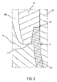
- the retraction bi-injection molding method only uses a single cavity, this cavity being however of variable shape and defined in a mold comprising a cavity 51, a fixed core 53, and at least one movable core 52 ( figures 2 and 3 ).
- the shape of the cavity is thus determined by the position of the movable core 52.
- a mold that can be used to realize the invention typically comprises a stationary core 53 occupying a central position and a movable core 52 having an annular shape, surrounding the fixed core 53, and slidably mounted in leaktight manner with respect to this fixed core 53 .
- the mobile core 52 is designed to be able to adopt a first position, illustrated in FIG. figure 2 , wherein said movable core rests sealingly on a front surface 510 of the impression 51.
- the cavity 51, the movable core 52, and the fixed core 53 together define a first hollow volume into which the first polymer P1 (FIG. 2) is injected to form at least the erect wall 3 of the container, and preferably also the bottom 2 in the same injection operation.
- the impression 51 and the movable core 52 are, in the first position of this movable core, radially separated from each other, outside the zone in which the movable core 52 rests on the frontal surface 510 of the impression 51, by an empty annular volume W.
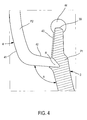
- the movable core 52 is moved away from the front surface 510 of the cavity 51, so as to adopt the second position illustrated in FIG. figure 3 , and to define a second hollow volume including the empty volume W, completely isolating the movable core 52 of the first polymer P1, and in which the second polymer P2 is injected.
- the figure 3 illustrates only a purely theoretical situation that could be obtained only by injecting the second polymer P2 at a very low speed, after cooling and final solidification of the first polymer, while the injection of the second polymer P2, immediately after injection of the first polymer, polymer P1, modifies the shape of the portion previously molded in this first polymer.
- the second polymer P2 enters the first polymer P1 in a connection zone R in which the flange 4 is connected to the wall 3, this penetration having the effect of developing a very large bonding force between the wall 3 and the flange 4.
- the second polymer P2 may typically have a thickness equal to plus or minus 10%, to the average thickness of the flange 4.
- the inner face 42 of the flange 4 connects to the wall 3 forming a layer 43 ( figure 4 ) which covers the wall 3 on the at least part of this wall 3 which is between the connection zone R and the edge 30 of the same wall 3.
- the layer 43 which may end with a bead 44, itself provides only a relatively modest binding force compared to that created by the penetration of the second polymer P2 in the first polymer P1, the presence this layer 43 attests that, in its second position ( figure 3 ), the movable core 52 is separated from the first polymer P1, this arrangement promoting the penetration of the second polymer P2 in the first polymer P1.
- the rim (4) is connected to the wall (3) along the edge (30).
- venting is provided at Y, which can lead to an invisible flash 6 possibly outside the container.
Landscapes
- Life Sciences & Earth Sciences (AREA)
- Engineering & Computer Science (AREA)
- Mechanical Engineering (AREA)
- Health & Medical Sciences (AREA)
- Environmental Sciences (AREA)
- Botany (AREA)
- Manufacturing & Machinery (AREA)
- Evolutionary Biology (AREA)
- General Health & Medical Sciences (AREA)
- Marine Sciences & Fisheries (AREA)
- Toxicology (AREA)
- Zoology (AREA)
- Injection Moulding Of Plastics Or The Like (AREA)
- Containers Having Bodies Formed In One Piece (AREA)
Description
- L'invention concerne, de façon générale, les techniques de moulage.
- Plus précisément, l'invention concerne un contenant moulé, selon le préambule de la revendication 1, par exemple utilisable comme pot d'horticulture, comprenant un fond s'étendant dans un plan principal et une paroi dressée de forme évasée se raccordant au fond et s'étendant, suivant une direction perpendiculaire au plan principal, jusqu'à un bord continu séparé du fond par une distance maximale, la paroi au moins étant réalisée par moulage dans un premier polymère thermoplastique le contenant moulé comprenant en outre un rebord s'étendant radialement autour du bord, ce rebord se raccordant à la paroi à plus grande proximité du bord que du fond et s'élevant jusqu'à atteindre, par rapport au fond, une hauteur supérieure à la distance maximale.
- Les contenants de ce type sont bien connus de l'homme du métier et sont couramment utilisés en raison de leur fabrication aisée et de leur coût de revient corrélativement faible.
- Par exemple, la demande de brevet
US 2008/0022589 divulgue un pot de fleur bi-couleur ressemblant à de l'émail. Selon ce document, le pot est réalisé par un procédé de moulage bi-injection mettant en oeuvre une seule opération d'extrusion. - En dépit de leurs avantages, les contenants connus de ce type présentent évidemment des qualités esthétiques et ornementales inférieures à celles des poteries fabriquées à la main.
- Bien que ces dernières soient en effet très difficiles à imiter dans le cadre d'une fabrication en grande série, l'invention a pour but de proposer une technique permettant au moins d'enrichir les qualités décoratives des contenants moulés en polymère.
- A cette fin, le contenant de l'invention, par ailleurs conforme à la définition générique qu'en donne le préambule ci-dessus, est essentiellement tel que le rebord est réalisé dans un deuxième polymère thermoplastique se distinguant du premier polymère au moins par sa couleur, le contenant moulé étant réalisé par un moulage bi-injection.
- Il est en outre souhaitable que la force de cohésion entre le rebord et la paroi soit suffisamment importante pour permettre à un utilisateur de soulever le contenant, avec son contenu, en tenant ce contenant par le rebord sans risquer une rupture de la liaison entre le rebord et la paroi en dépit du caractère nécessairement localisé de cette liaison.
- Pour ce faire, la paroi et le rebord présentent une épaisseur moyenne égale, à plus ou moins 25% près, à 0,5+ (0,065.V) millimètres, où V est le volume du contenant exprimé en litres.
- En outre, il est judicieux de prévoir que le rebord présente une face externe se raccordant à la paroi en formant avec cette paroi un angle au plus égal à 150 degrés, et que le deuxième polymère pénètre dans le premier polymère dans une zone de raccordement dans laquelle le rebord se raccorde à la paroi.
- Une telle structure peut être obtenue en réalisant le contenant par un moulage bi-injection par rétraction.
- Il est alors possible de faire en sorte que, dans la zone de raccordement, le deuxième polymère présente une épaisseur égale, à plus ou moins 10% près, à l'épaisseur moyenne du rebord.
- Par ailleurs, il est souhaitable que le rebord présente une face interne se raccordant à la paroi en formant une couche recouvrant la paroi sur une partie au moins de cette paroi comprise entre la zone de raccordement et le bord de la paroi.
- Dans une autre solution, le rebord se raccorde à la paroi le long du bord.
- En outre, chacun des premier et deuxième polymères est de préférence teinté dans la masse, et l'un au moins des premier et deuxième polymères contient du polypropylène en tant que constituant d'un mélange ou en tant que copolymère.
- Dans le mode de réalisation préféré de l'invention, le fond et la paroi sont réalisés d'une seule pièce par moulage dans le premier polymère thermoplastique.
- D'autres caractéristiques et avantages de l'invention ressortiront clairement de la description qui en est faite ci-après, à titre indicatif et nullement limitatif, en référence aux dessins annexés, dans lesquels :
- la
figure 1 est une vue en coupe axiale d'un contenant conforme à un mode de réalisation de l'invention; - la
figure 2 est une vue en coupe axiale à échelle agrandie d'une partie d'un contenant conforme à un premier mode de réalisation de l'invention illustré après injection du premier polymère dans un moule à rétractation, la partie représentée étant constituée par la partie supérieure de la paroi; - la
figure 3 est une vue en coupe axiale à échelle agrandie d'une partie du contenant conforme au mode de réalisation de lafigure 2 , illustré après injection du deuxième polymère dans le moule à rétraction de lafigure 2 , la partie représentée étant constituée par la partie supérieure de la paroi, par le rebord, et par la liaison entre le rebord et la paroi, tels que ces éléments devraient se présenter en théorie si le deuxième polymère était injecté à vitesse réduite après refroidissement et solidification définitive du premier polymère - - la
figure 4 est une vue en coupe axiale à échelle agrandie d'une partie du contenant conforme au mode de réalisation desfigures 2 et3 , illustré après fabrication dans le moule à rétraction desfigures 2 et3 , la partie représentée étant constituée par la partie supérieure de la paroi, par le rebord, et par la liaison entre le rebord et la paroi, tels que ces éléments se présentent en réalité, - les
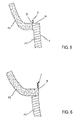
figures 5 et 6 sont des vues en coupe axiale d'un deuxième et d'un troisième modes de réalisation de l'invention, tels que la paroi, le rebord et la liaison entre le rebord et la paroi devraient se présenter en théorie si le deuxième polymère était injecté après solidification définitive du premier polymère. - Comme annoncé précédemment, l'invention concerne notamment un contenant 1 moulé, par exemple conçu pour constituer un pot d'horticulture.
- Comme le montre la
figure 1 , un tel contenant 1 présente essentiellement un fond 2 s'étendant dans un plan principal Q, et une paroi dressée 3 de forme évasée se raccordant au fond 2. - La paroi 3 s'étend, suivant une direction Z perpendiculaire au plan principal Q, jusqu'à un bord continu 30 séparé du fond 2 par une distance maximale D.
- En général, le bord 30 s'étend dans un plan parallèle au plan Q, de sorte que tous les points du bord continu 30 sont à la même distance D du fond 2.
- Le fond 2 et la paroi 3 sont de préférence réalisés d'une seule pièce par moulage dans un premier polymère thermoplastique P1 par exemple teinté dans la masse et contenant du polypropylène en tant que constituant d'un mélange ou en tant que copolymère.
- Le contenant de l'invention comprend en outre un rebord 4 qui s'étend radialement autour du bord 30 et qui se raccorde à la paroi 3 à plus grande proximité du bord 30 que du fond 2, typiquement à quelques millimètres du bord 30.
- D'autre part, ce rebord 4 s'élève jusqu'à atteindre, par rapport au fond 2, une hauteur H supérieure à la distance maximale D.
- Typiquement, la hauteur H est supérieure de quelques centimètres à la distance maximale D, de sorte que le bord 30 de la paroi 3 est caché, par le rebord 4, à la vue de tout observateur examinant le contenant 1 de l'extérieur en plaçant son oeil dans un plan transversal à la normale au fond 2 et situé à mi-hauteur de la paroi 3.
- Par ailleurs, le rebord 4 est réalisé dans un deuxième polymère thermoplastique P2 qui se distingue du premier polymère au moins par sa couleur, ce deuxième polymère pouvant en revanche être lui aussi teinté dans la masse et être soit identique au premier polymère, soit au moins appartenir à la même famille chimique de polymères.
- En particulier, le deuxième polymère P2 contient de préférence du polypropylène en tant que constituant d'un mélange ou en tant que copolymère.
- L'expression teinté dans la masse signifie que le polymère a été coloré avant injection dans le moule, quelque soit le procédé utilisé pour obtenir la coloration recherchée, cette définition s'appliquant à la fois au polymère 1 et au polymère 2.
- L'épaisseur moyenne de la paroi 3 et du rebord 4 peut adéquatement être comprise entre 0,45 et 1,5 millimètres pour des contenants compris entre 0,5 et 15 litres, et comprise entre 1,2 et 2,5 millimètres pour des contenants compris entre 15 et 30 litres.
- De manière plus précise, la paroi 3 et le rebord 4 présentent une épaisseur moyenne égale, à plus ou moins 25% près, à 0,5+ (0,065.V) millimètres, où V est le volume du contenant exprimé en litres.
- La variation de plus ou moins 25 % correspond à la rigidité recherchée du contenant, sans relation avec les contraintes d'industrialisation de ce contenant ou avec la qualité de la soudure entre la paroi et le rebord.
- Comme le montrent les
figures 2 et3 , le contenant de l'invention est très avantageusement réalisé par un moulage bi-injection par rétraction. - Il existe en effet deux grandes familles de procédés de moulage bi-injection, à savoir le moulage par transfert et le moulage par rétraction.
- Dans le procédé de moulage bi-injection par transfert, la première injection est réalisée dans une première cavité.
- La pièce résultant de cette première injection est ensuite démoulée et transférée dans une deuxième cavité dont la forme contient le volume de la pièce finie telle qu'elle résultera des première et deuxième injections.
- La deuxième injection est alors réalisée dans l'espace laissé disponible, dans la deuxième cavité, par la pièce résultant de la première injection.
- Le procédé de moulage bi-injection par rétraction n'utilise quant à lui qu'une seule cavité, cette cavité étant en revanche de forme variable et définie dans un moule comprenant une empreinte 51, un noyau fixe 53, et au moins un noyau mobile 52 (
figures 2 et3 ). - Dans un tel agencement, la forme de la cavité est donc déterminée par la position du noyau mobile 52.
- Plus précisément, un moule utilisable pour réaliser l'invention comprend typiquement un noyau fixe 53 occupant une position centrale et un noyau mobile 52 présentant une forme annulaire, entourant le noyau fixe 53, et monté coulissant de façon étanche par rapport à ce noyau fixe 53.
- Par ailleurs, le noyau mobile 52 est conçu pour pouvoir adopter une première position, illustrée à la
figure 2 , dans laquelle ce noyau mobile s'appuie de façon étanche sur une surface frontale 510 de l'empreinte 51. - Dans cette première position du noyau mobile 52, l'empreinte 51, le noyau mobile 52, et le noyau fixe 53 délimitent ensemble un premier volume creux dans lequel est injecté le premier polymère P1 (figue 2) pour constituer au moins la paroi dressée 3 du contenant, et de préférence également le fond 2 dans la même opération d'injection.
- Cependant, comme le montre encore la
figure 2 , l'empreinte 51 et le noyau mobile 52 sont, dans la première position de ce noyau mobile, radialement séparés l'un de l'autre, à l'extérieur de la zone dans laquelle le noyau mobile 52 s'appuie sur la surface frontale 510 de l'empreinte 51, par un volume annulaire vide W. - Juste après l'injection du polymère P1 dans le moule configuré comme illustré à la
figure 2 , le noyau mobile 52 est éloigné de la surface frontale 510 de l'empreinte 51, de manière à adopter la deuxième position illustrée à lafigure 3 , et à définir un deuxième volume creux incluant le volume vide W, isolant totalement le noyau mobile 52 du premier polymère P1, et dans lequel est injecté le deuxième polymère P2. - En réalité, la
figure 3 n'illustre qu'une situation purement théorique qui ne pourrait être obtenue que par injection du deuxième polymère P2 à très basse vitesse, après refroidissement et solidification définitive du premier polymère, alors que l'injection du deuxième polymère P2, immédiatement après injection du premier polymère P1, modifie la forme de la partie préalablement moulée dans ce premier polymère. - Plus précisément, et pour autant que la face externe 41 du rebord 4 se raccorde à la paroi 3 en formant avec cette paroi un angle A au plus égal à 150 degrés, le deuxième polymère P2 pénètre dans le premier polymère P1 dans une zone de raccordement R dans laquelle le rebord 4 se raccorde à la paroi 3, cette pénétration ayant pour effet de développer une force de liaison très importante entre la paroi 3 et le rebord 4.
- Dans la zone de raccordement R, le deuxième polymère P2 peut typiquement présenter une épaisseur égale, à plus ou moins 10% près, à l'épaisseur moyenne du rebord 4.
- Dans la mesure où, après le retrait du noyau mobile 52 à distance de la surface frontale 510 de l'empreinte 51 (
figure 3 ), le noyau mobile 52 n'est plus en contact avec le premier polymère, la face interne 42 du rebord 4 se raccorde à la paroi 3 en formant une couche 43 (figure 4 ) qui recouvre la paroi 3 sur la partie au moins de cette paroi 3 qui est comprise entre la zone de raccordement R et le bord 30 de cette même paroi 3. - Bien que la couche 43, qui peut se terminer par un bourrelet 44, n'apporte par elle-même qu'une force de liaison relativement modeste par rapport à celle que crée la pénétration du deuxième polymère P2 dans le premier polymère P1, la présence de cette couche 43 atteste que, dans sa deuxième position (
figure 3 ), le noyau mobile 52 est écarté du premier polymère P1, cet agencement favorisant la pénétration du deuxième polymère P2 dans le premier polymère P1. - Dans une autre solution de l'invention, le rebord (4) se raccorde à la paroi (3) le long du bord (30).
- Selon les
figures 5 et 6 , l'éventation est assurée en Y, ce qui peut conduire à une bavure 6 éventuelle invisible à l'extérieur du contenant.
Claims (6)
- Contenant (1) moulé par bi-injection comprenant un fond (2) s'étendant dans un plan principal (Q) et une paroi dressée (3) de forme évasée se raccordant au fond (2) et s'étendant, suivant une direction (Z) perpendiculaire au plan principal (Q), jusqu'à un bord continu (30) séparé du fond (2) par une distance maximale (D), la paroi (3) au moins étant réalisée par moulage dans un premier polymère thermoplastique (P1), le contenant moulé (1) comprenant en outre un rebord (4) s'étendant radialement autour du bord (30), et ce rebord (4) se raccorde à la paroi (3) à plus grande proximité du bord (30) que du fond (2) et, ce rebord (4) s'élevant jusqu'à atteindre, par rapport au fond (2), une hauteur (H) supérieure à la distance maximale (D), le rebord (4) étant réalisé dans un deuxième polymère thermoplastique (P2) se distinguant du premier polymère (P1) au moins par sa couleur, le contenant moulé (1) étant caractérisé en ce qu'il est réalisé par un moulage bi-injection par rétraction utilisant une seule cavité de forme variable et définie dans un moule comprenant une empreinte (51), un noyau fixe (53), et au moins un noyau mobile (52) et que la paroi (3) et le rebord (4) présentent une épaisseur moyenne égale, à plus ou moins 25% près, à 0,5 + (0,065 x V) millimètres, où V est le volume du contenant exprimé en litres.
- Contenant suivant la revendication 1, caractérisé en ce que le rebord (4) présente une face externe (41) se raccordant à la paroi (3) en formant avec cette paroi un angle (A) au plus égal à 150 degrés, et en ce que le deuxième polymère (P2) pénètre dans le premier polymère (P1) dans une zone de raccordement (R) dans laquelle le rebord (4) se raccorde à la paroi (3).
- Contenant suivant la revendication 2, caractérisé en ce que, dans la zone de raccordement (R), le deuxième polymère (P2) présente une épaisseur égale, à plus ou moins 10% près, à l'épaisseur moyenne du rebord (4).
- Contenant suivant l'une quelconque des revendications 2 et 3, caractérisé en ce que le rebord (4) présente une face interne (42) se raccordant à la paroi (3) en formant une couche (43) recouvrant la paroi (3) sur une partie au moins de cette paroi (3) comprise entre la zone de raccordement (R) et le bord (30) de la paroi (3).
- Contenant suivant la revendication 2, caractérisé en ce que le rebord (4) se raccorde à la paroi (3) le long du bord (30).
- Contenant suivant l'une quelconque des revendications précédentes, caractérisé en ce que chacun des premier et deuxième polymères (P1, P2) est teinté dans la masse, et en ce que l'un au moins des premier et deuxième polymères (P1, P2) contient du polypropylène en tant que constituant d'un mélange ou en tant que copolymère.
Applications Claiming Priority (1)
| Application Number | Priority Date | Filing Date | Title |
|---|---|---|---|
| FR1150548A FR2970704B1 (fr) | 2011-01-24 | 2011-01-24 | Contenant perfectionne obtenu par moulage bi-injection |
Publications (2)
| Publication Number | Publication Date |
|---|---|
| EP2479121A1 EP2479121A1 (fr) | 2012-07-25 |
| EP2479121B1 true EP2479121B1 (fr) | 2014-04-23 |
Family
ID=44169158
Family Applications (1)
| Application Number | Title | Priority Date | Filing Date |
|---|---|---|---|
| EP20120151872 Not-in-force EP2479121B1 (fr) | 2011-01-24 | 2012-01-20 | Contenant perfectionné obtenu par moulage bi-injection. |
Country Status (2)
| Country | Link |
|---|---|
| EP (1) | EP2479121B1 (fr) |
| FR (1) | FR2970704B1 (fr) |
Families Citing this family (1)
| Publication number | Priority date | Publication date | Assignee | Title |
|---|---|---|---|---|
| FR3005890B1 (fr) * | 2013-05-24 | 2015-10-16 | Georges David Ets | Procede de moulage de pots de fleurs bicolores et pot fabrique selon ce procede |
Family Cites Families (4)
| Publication number | Priority date | Publication date | Assignee | Title |
|---|---|---|---|---|
| DE4224171A1 (de) * | 1992-07-22 | 1994-01-27 | Bosch Gmbh Robert | Spritzgußteil sowie Verfahren und Spritzgießwerkzeug zum Herstellen von Spritzgußteilen |
| DE19711887A1 (de) * | 1997-03-21 | 1998-10-15 | Optipack Gmbh & Co Kg | Verpackungsbecher für Desserts |
| WO2005068152A2 (fr) * | 2004-01-03 | 2005-07-28 | Johnson Controls Technology Company | Piece de vehicule et procede pour realiser une piece de vehicule |
| ITPT20060018U1 (it) * | 2006-07-28 | 2008-01-29 | I De L S R L | Vaso da fiori bicolore con bordo apparentemente smaltato |
-
2011
- 2011-01-24 FR FR1150548A patent/FR2970704B1/fr not_active Expired - Fee Related
-
2012
- 2012-01-20 EP EP20120151872 patent/EP2479121B1/fr not_active Not-in-force
Also Published As
| Publication number | Publication date |
|---|---|
| FR2970704A1 (fr) | 2012-07-27 |
| FR2970704B1 (fr) | 2014-04-04 |
| EP2479121A1 (fr) | 2012-07-25 |
Similar Documents
| Publication | Publication Date | Title |
|---|---|---|
| EP2349678B1 (fr) | Moule pour le soufflage de recipients a fond renforce, utilisation de ce moule et reciepent | |
| EP1136239B1 (fr) | Procédé de fabrication d'une pièce en matière plastique renforcée et moule | |
| CA2557584C (fr) | Structure multicouche | |
| EP4095052B1 (fr) | Fond de moule pour la fabrication d'un récipient | |
| EP2444331A1 (fr) | Emballage flexible fabriqué par soudage et contenant une matière recyclée ou issue de ressources renouvelables | |
| EP2580132B1 (fr) | Récipient comprenant un fond voûté nervuré | |
| EP2580133B1 (fr) | Récipient comprenant un fond voûté à assise carrée | |
| WO2008096290A2 (fr) | Méthode de réalisation d'un objet multicouche | |
| EP2479121B1 (fr) | Contenant perfectionné obtenu par moulage bi-injection. | |
| FR2647051A1 (fr) | Procede pour la mise en forme d'une plaque composite formee par l'association d'une nappe textile et d'une feuille en matiere plastique thermoformable et installation pour sa mise en oeuvre | |
| FR2909302A1 (fr) | Procede de realisation de pots massifs par injection de matieres plastiques | |
| EP2812169B1 (fr) | Procédé de réalisation d'un ensemble plan-vasque et ensemble plan-vasque obtenu par ce procédé | |
| WO2008135657A2 (fr) | Surmoulage d'une tète de tube sur une extrémité de jupe permettant d'obtenir un tube ayant un taux de restitution élevé | |
| FR3059306B1 (fr) | Pots a contre-depouille, moules ouvrants, machines de formages et lignes de fabrication de pots a contre-depouille | |
| EP2468646B1 (fr) | Contenant décoré obtenu par moulage et son moule de fabrication | |
| EP1919680B1 (fr) | Objets multicouches et methode de realisation | |
| EP1957322B1 (fr) | Piece d'habillage | |
| EP0724942A1 (fr) | Procédé de réalisation de pièces composites en matière plastique comportant un revêtement de surface, moules pour sa mise en oeuvre et pièces composites ainsi obtenues | |
| EP3515683A1 (fr) | Fond de moule pourvu de canaux de décompression débouchant sur une face supérieure périphérique | |
| EP1057698B1 (fr) | Couvercle pour un module airbag, volant de direction le comportant et procédé d'obtention de ce couvercle | |
| EP1179483B1 (fr) | Récipient ayant un bord à paroi multiple et son procédé de fabrication | |
| FR2902040A1 (fr) | Procede pour realiser un recipient en matiere plastique et recipient obtenu avec un tel procede | |
| FR3029132A1 (fr) | Procede de surmoulage d'un insert pre-impregne et son utilisation | |
| FR3005890A1 (fr) | Procede de moulage de pots de fleurs bicolores et pot fabrique selon ce procede | |
| EP1095840B1 (fr) | Volant de direction pour véhicule et son procédé de fabrication |
Legal Events
| Date | Code | Title | Description |
|---|---|---|---|
| PUAI | Public reference made under article 153(3) epc to a published international application that has entered the european phase |
Free format text: ORIGINAL CODE: 0009012 |
|
| AK | Designated contracting states |
Kind code of ref document: A1 Designated state(s): AL AT BE BG CH CY CZ DE DK EE ES FI FR GB GR HR HU IE IS IT LI LT LU LV MC MK MT NL NO PL PT RO RS SE SI SK SM TR |
|
| AX | Request for extension of the european patent |
Extension state: BA ME |
|
| 17P | Request for examination filed |
Effective date: 20130204 |
|
| 17Q | First examination report despatched |
Effective date: 20130321 |
|
| GRAP | Despatch of communication of intention to grant a patent |
Free format text: ORIGINAL CODE: EPIDOSNIGR1 |
|
| INTG | Intention to grant announced |
Effective date: 20131113 |
|
| GRAS | Grant fee paid |
Free format text: ORIGINAL CODE: EPIDOSNIGR3 |
|
| GRAA | (expected) grant |
Free format text: ORIGINAL CODE: 0009210 |
|
| AK | Designated contracting states |
Kind code of ref document: B1 Designated state(s): AL AT BE BG CH CY CZ DE DK EE ES FI FR GB GR HR HU IE IS IT LI LT LU LV MC MK MT NL NO PL PT RO RS SE SI SK SM TR |
|
| REG | Reference to a national code |
Ref country code: GB Ref legal event code: FG4D Free format text: NOT ENGLISH |
|
| REG | Reference to a national code |
Ref country code: CH Ref legal event code: EP |
|
| REG | Reference to a national code |
Ref country code: AT Ref legal event code: REF Ref document number: 663685 Country of ref document: AT Kind code of ref document: T Effective date: 20140515 |
|
| REG | Reference to a national code |
Ref country code: IE Ref legal event code: FG4D Free format text: LANGUAGE OF EP DOCUMENT: FRENCH |
|
| REG | Reference to a national code |
Ref country code: DE Ref legal event code: R096 Ref document number: 602012001442 Country of ref document: DE Effective date: 20140605 |
|
| REG | Reference to a national code |
Ref country code: AT Ref legal event code: MK05 Ref document number: 663685 Country of ref document: AT Kind code of ref document: T Effective date: 20140423 |
|
| REG | Reference to a national code |
Ref country code: NL Ref legal event code: VDEP Effective date: 20140423 |
|
| REG | Reference to a national code |
Ref country code: LT Ref legal event code: MG4D |
|
| PG25 | Lapsed in a contracting state [announced via postgrant information from national office to epo] |
Ref country code: IS Free format text: LAPSE BECAUSE OF FAILURE TO SUBMIT A TRANSLATION OF THE DESCRIPTION OR TO PAY THE FEE WITHIN THE PRESCRIBED TIME-LIMIT Effective date: 20140823 Ref country code: FI Free format text: LAPSE BECAUSE OF FAILURE TO SUBMIT A TRANSLATION OF THE DESCRIPTION OR TO PAY THE FEE WITHIN THE PRESCRIBED TIME-LIMIT Effective date: 20140423 Ref country code: BG Free format text: LAPSE BECAUSE OF FAILURE TO SUBMIT A TRANSLATION OF THE DESCRIPTION OR TO PAY THE FEE WITHIN THE PRESCRIBED TIME-LIMIT Effective date: 20140723 Ref country code: GR Free format text: LAPSE BECAUSE OF FAILURE TO SUBMIT A TRANSLATION OF THE DESCRIPTION OR TO PAY THE FEE WITHIN THE PRESCRIBED TIME-LIMIT Effective date: 20140724 Ref country code: LT Free format text: LAPSE BECAUSE OF FAILURE TO SUBMIT A TRANSLATION OF THE DESCRIPTION OR TO PAY THE FEE WITHIN THE PRESCRIBED TIME-LIMIT Effective date: 20140423 Ref country code: CY Free format text: LAPSE BECAUSE OF FAILURE TO SUBMIT A TRANSLATION OF THE DESCRIPTION OR TO PAY THE FEE WITHIN THE PRESCRIBED TIME-LIMIT Effective date: 20140423 Ref country code: NL Free format text: LAPSE BECAUSE OF FAILURE TO SUBMIT A TRANSLATION OF THE DESCRIPTION OR TO PAY THE FEE WITHIN THE PRESCRIBED TIME-LIMIT Effective date: 20140423 Ref country code: NO Free format text: LAPSE BECAUSE OF FAILURE TO SUBMIT A TRANSLATION OF THE DESCRIPTION OR TO PAY THE FEE WITHIN THE PRESCRIBED TIME-LIMIT Effective date: 20140723 |
|
| PG25 | Lapsed in a contracting state [announced via postgrant information from national office to epo] |
Ref country code: PL Free format text: LAPSE BECAUSE OF FAILURE TO SUBMIT A TRANSLATION OF THE DESCRIPTION OR TO PAY THE FEE WITHIN THE PRESCRIBED TIME-LIMIT Effective date: 20140423 Ref country code: RS Free format text: LAPSE BECAUSE OF FAILURE TO SUBMIT A TRANSLATION OF THE DESCRIPTION OR TO PAY THE FEE WITHIN THE PRESCRIBED TIME-LIMIT Effective date: 20140423 Ref country code: AT Free format text: LAPSE BECAUSE OF FAILURE TO SUBMIT A TRANSLATION OF THE DESCRIPTION OR TO PAY THE FEE WITHIN THE PRESCRIBED TIME-LIMIT Effective date: 20140423 Ref country code: ES Free format text: LAPSE BECAUSE OF FAILURE TO SUBMIT A TRANSLATION OF THE DESCRIPTION OR TO PAY THE FEE WITHIN THE PRESCRIBED TIME-LIMIT Effective date: 20140423 Ref country code: SE Free format text: LAPSE BECAUSE OF FAILURE TO SUBMIT A TRANSLATION OF THE DESCRIPTION OR TO PAY THE FEE WITHIN THE PRESCRIBED TIME-LIMIT Effective date: 20140423 Ref country code: HR Free format text: LAPSE BECAUSE OF FAILURE TO SUBMIT A TRANSLATION OF THE DESCRIPTION OR TO PAY THE FEE WITHIN THE PRESCRIBED TIME-LIMIT Effective date: 20140423 Ref country code: LV Free format text: LAPSE BECAUSE OF FAILURE TO SUBMIT A TRANSLATION OF THE DESCRIPTION OR TO PAY THE FEE WITHIN THE PRESCRIBED TIME-LIMIT Effective date: 20140423 |
|
| PG25 | Lapsed in a contracting state [announced via postgrant information from national office to epo] |
Ref country code: PT Free format text: LAPSE BECAUSE OF FAILURE TO SUBMIT A TRANSLATION OF THE DESCRIPTION OR TO PAY THE FEE WITHIN THE PRESCRIBED TIME-LIMIT Effective date: 20140825 |
|
| REG | Reference to a national code |
Ref country code: DE Ref legal event code: R097 Ref document number: 602012001442 Country of ref document: DE |
|
| PG25 | Lapsed in a contracting state [announced via postgrant information from national office to epo] |
Ref country code: CZ Free format text: LAPSE BECAUSE OF FAILURE TO SUBMIT A TRANSLATION OF THE DESCRIPTION OR TO PAY THE FEE WITHIN THE PRESCRIBED TIME-LIMIT Effective date: 20140423 Ref country code: RO Free format text: LAPSE BECAUSE OF FAILURE TO SUBMIT A TRANSLATION OF THE DESCRIPTION OR TO PAY THE FEE WITHIN THE PRESCRIBED TIME-LIMIT Effective date: 20140423 Ref country code: SK Free format text: LAPSE BECAUSE OF FAILURE TO SUBMIT A TRANSLATION OF THE DESCRIPTION OR TO PAY THE FEE WITHIN THE PRESCRIBED TIME-LIMIT Effective date: 20140423 Ref country code: DK Free format text: LAPSE BECAUSE OF FAILURE TO SUBMIT A TRANSLATION OF THE DESCRIPTION OR TO PAY THE FEE WITHIN THE PRESCRIBED TIME-LIMIT Effective date: 20140423 Ref country code: EE Free format text: LAPSE BECAUSE OF FAILURE TO SUBMIT A TRANSLATION OF THE DESCRIPTION OR TO PAY THE FEE WITHIN THE PRESCRIBED TIME-LIMIT Effective date: 20140423 |
|
| PLBE | No opposition filed within time limit |
Free format text: ORIGINAL CODE: 0009261 |
|
| STAA | Information on the status of an ep patent application or granted ep patent |
Free format text: STATUS: NO OPPOSITION FILED WITHIN TIME LIMIT |
|
| PG25 | Lapsed in a contracting state [announced via postgrant information from national office to epo] |
Ref country code: IT Free format text: LAPSE BECAUSE OF FAILURE TO SUBMIT A TRANSLATION OF THE DESCRIPTION OR TO PAY THE FEE WITHIN THE PRESCRIBED TIME-LIMIT Effective date: 20140423 |
|
| 26N | No opposition filed |
Effective date: 20150126 |
|
| REG | Reference to a national code |
Ref country code: DE Ref legal event code: R097 Ref document number: 602012001442 Country of ref document: DE Effective date: 20150126 |
|
| PG25 | Lapsed in a contracting state [announced via postgrant information from national office to epo] |
Ref country code: BE Free format text: LAPSE BECAUSE OF NON-PAYMENT OF DUE FEES Effective date: 20150131 |
|
| PG25 | Lapsed in a contracting state [announced via postgrant information from national office to epo] |
Ref country code: SI Free format text: LAPSE BECAUSE OF FAILURE TO SUBMIT A TRANSLATION OF THE DESCRIPTION OR TO PAY THE FEE WITHIN THE PRESCRIBED TIME-LIMIT Effective date: 20140423 |
|
| REG | Reference to a national code |
Ref country code: CH Ref legal event code: PL |
|
| PG25 | Lapsed in a contracting state [announced via postgrant information from national office to epo] |
Ref country code: LU Free format text: LAPSE BECAUSE OF FAILURE TO SUBMIT A TRANSLATION OF THE DESCRIPTION OR TO PAY THE FEE WITHIN THE PRESCRIBED TIME-LIMIT Effective date: 20150120 |
|
| PG25 | Lapsed in a contracting state [announced via postgrant information from national office to epo] |
Ref country code: MC Free format text: LAPSE BECAUSE OF FAILURE TO SUBMIT A TRANSLATION OF THE DESCRIPTION OR TO PAY THE FEE WITHIN THE PRESCRIBED TIME-LIMIT Effective date: 20140423 |
|
| PG25 | Lapsed in a contracting state [announced via postgrant information from national office to epo] |
Ref country code: CH Free format text: LAPSE BECAUSE OF NON-PAYMENT OF DUE FEES Effective date: 20150131 Ref country code: LI Free format text: LAPSE BECAUSE OF NON-PAYMENT OF DUE FEES Effective date: 20150131 |
|
| REG | Reference to a national code |
Ref country code: IE Ref legal event code: MM4A |
|
| REG | Reference to a national code |
Ref country code: FR Ref legal event code: PLFP Year of fee payment: 5 |
|
| PG25 | Lapsed in a contracting state [announced via postgrant information from national office to epo] |
Ref country code: IE Free format text: LAPSE BECAUSE OF NON-PAYMENT OF DUE FEES Effective date: 20150120 |
|
| PGFP | Annual fee paid to national office [announced via postgrant information from national office to epo] |
Ref country code: GB Payment date: 20160125 Year of fee payment: 5 |
|
| REG | Reference to a national code |
Ref country code: FR Ref legal event code: PLFP Year of fee payment: 6 |
|
| PG25 | Lapsed in a contracting state [announced via postgrant information from national office to epo] |
Ref country code: MT Free format text: LAPSE BECAUSE OF FAILURE TO SUBMIT A TRANSLATION OF THE DESCRIPTION OR TO PAY THE FEE WITHIN THE PRESCRIBED TIME-LIMIT Effective date: 20140423 |
|
| PG25 | Lapsed in a contracting state [announced via postgrant information from national office to epo] |
Ref country code: HU Free format text: LAPSE BECAUSE OF FAILURE TO SUBMIT A TRANSLATION OF THE DESCRIPTION OR TO PAY THE FEE WITHIN THE PRESCRIBED TIME-LIMIT; INVALID AB INITIO Effective date: 20120120 Ref country code: SM Free format text: LAPSE BECAUSE OF FAILURE TO SUBMIT A TRANSLATION OF THE DESCRIPTION OR TO PAY THE FEE WITHIN THE PRESCRIBED TIME-LIMIT Effective date: 20140423 |
|
| PG25 | Lapsed in a contracting state [announced via postgrant information from national office to epo] |
Ref country code: TR Free format text: LAPSE BECAUSE OF FAILURE TO SUBMIT A TRANSLATION OF THE DESCRIPTION OR TO PAY THE FEE WITHIN THE PRESCRIBED TIME-LIMIT Effective date: 20140423 |
|
| GBPC | Gb: european patent ceased through non-payment of renewal fee |
Effective date: 20170120 |
|
| REG | Reference to a national code |
Ref country code: FR Ref legal event code: PLFP Year of fee payment: 7 |
|
| PG25 | Lapsed in a contracting state [announced via postgrant information from national office to epo] |
Ref country code: GB Free format text: LAPSE BECAUSE OF NON-PAYMENT OF DUE FEES Effective date: 20170120 |
|
| PG25 | Lapsed in a contracting state [announced via postgrant information from national office to epo] |
Ref country code: MK Free format text: LAPSE BECAUSE OF FAILURE TO SUBMIT A TRANSLATION OF THE DESCRIPTION OR TO PAY THE FEE WITHIN THE PRESCRIBED TIME-LIMIT Effective date: 20140423 |
|
| PG25 | Lapsed in a contracting state [announced via postgrant information from national office to epo] |
Ref country code: AL Free format text: LAPSE BECAUSE OF FAILURE TO SUBMIT A TRANSLATION OF THE DESCRIPTION OR TO PAY THE FEE WITHIN THE PRESCRIBED TIME-LIMIT Effective date: 20140423 |
|
| PGFP | Annual fee paid to national office [announced via postgrant information from national office to epo] |
Ref country code: FR Payment date: 20190130 Year of fee payment: 8 Ref country code: DE Payment date: 20190130 Year of fee payment: 8 |
|
| REG | Reference to a national code |
Ref country code: DE Ref legal event code: R119 Ref document number: 602012001442 Country of ref document: DE |
|
| PG25 | Lapsed in a contracting state [announced via postgrant information from national office to epo] |
Ref country code: DE Free format text: LAPSE BECAUSE OF NON-PAYMENT OF DUE FEES Effective date: 20200801 Ref country code: FR Free format text: LAPSE BECAUSE OF NON-PAYMENT OF DUE FEES Effective date: 20200131 |