EP2479022A1 - Powder press - Google Patents
Powder press Download PDFInfo
- Publication number
- EP2479022A1 EP2479022A1 EP11151833A EP11151833A EP2479022A1 EP 2479022 A1 EP2479022 A1 EP 2479022A1 EP 11151833 A EP11151833 A EP 11151833A EP 11151833 A EP11151833 A EP 11151833A EP 2479022 A1 EP2479022 A1 EP 2479022A1
- Authority
- EP
- European Patent Office
- Prior art keywords
- intermediate member
- die plate
- plate
- screw
- flexible
- Prior art date
- Legal status (The legal status is an assumption and is not a legal conclusion. Google has not performed a legal analysis and makes no representation as to the accuracy of the status listed.)
- Withdrawn
Links
Images


Classifications
-
- B—PERFORMING OPERATIONS; TRANSPORTING
- B30—PRESSES
- B30B—PRESSES IN GENERAL
- B30B11/00—Presses specially adapted for forming shaped articles from material in particulate or plastic state, e.g. briquetting presses, tabletting presses
- B30B11/02—Presses specially adapted for forming shaped articles from material in particulate or plastic state, e.g. briquetting presses, tabletting presses using a ram exerting pressure on the material in a moulding space
- B30B11/04—Presses specially adapted for forming shaped articles from material in particulate or plastic state, e.g. briquetting presses, tabletting presses using a ram exerting pressure on the material in a moulding space co-operating with a fixed mould
-
- B—PERFORMING OPERATIONS; TRANSPORTING
- B30—PRESSES
- B30B—PRESSES IN GENERAL
- B30B15/00—Details of, or accessories for, presses; Auxiliary measures in connection with pressing
- B30B15/007—Means for maintaining the press table, the press platen or the press ram against tilting or deflection
-
- B—PERFORMING OPERATIONS; TRANSPORTING
- B30—PRESSES
- B30B—PRESSES IN GENERAL
- B30B15/00—Details of, or accessories for, presses; Auxiliary measures in connection with pressing
- B30B15/02—Dies; Inserts therefor; Mounting thereof; Moulds
-
- B—PERFORMING OPERATIONS; TRANSPORTING
- B30—PRESSES
- B30B—PRESSES IN GENERAL
- B30B15/00—Details of, or accessories for, presses; Auxiliary measures in connection with pressing
- B30B15/04—Frames; Guides
-
- B—PERFORMING OPERATIONS; TRANSPORTING
- B30—PRESSES
- B30B—PRESSES IN GENERAL
- B30B15/00—Details of, or accessories for, presses; Auxiliary measures in connection with pressing
- B30B15/06—Platens or press rams
-
- B—PERFORMING OPERATIONS; TRANSPORTING
- B30—PRESSES
- B30B—PRESSES IN GENERAL
- B30B15/00—Details of, or accessories for, presses; Auxiliary measures in connection with pressing
- B30B15/06—Platens or press rams
- B30B15/068—Drive connections, e.g. pivotal
-
- B—PERFORMING OPERATIONS; TRANSPORTING
- B30—PRESSES
- B30B—PRESSES IN GENERAL
- B30B15/00—Details of, or accessories for, presses; Auxiliary measures in connection with pressing
- B30B15/28—Arrangements for preventing distortion of, or damage to, presses or parts thereof
Definitions
- the invention relates to a powder press for producing a compact of a powdery material.
- a powder press has a frame, a punch assembly and a die assembly.
- the latter defines a mold cavity into which the powdered material can be filled, whereupon, to form the compact, the punch assembly and die assembly can be moved relative to one another along a press vertical axis and pressed against each other.
- the drive of the die assembly or the punch assembly is usually via two mutually parallel to the vertical axis of the press acting drives, each with a servo motor.
- the two servomotors work in master-slave mode to ensure a largely synchronous movement of the two parallel drives along or parallel to the vertical axis.
- the invention has for its object to largely eliminate this residual risk.
- This construction according to the invention ensures that even with a difference between the travel path of the first drive means extending along the press stroke axis ZZ (eg vertical direction) and the second drive means acting in parallel therewith, the tractive force or thrust force with a very low tilting moment or practically is entered without tilting moment in the die plate or in the stamp plate.
- the introduction of force from the two parallel drives into the die plate and / or into the die plate takes place via a die plate intermediate member into the die plate and / or via a stamp plate intermediate member into the die plate, depending on the structure of the press.
- the two parallel drives, the die plate and / or the stamp plate are rigid structures, which due to their geometry, such as. relatively thick formation of the plate, stiffening ribs on the plate, etc., as well as due to the plate material, e.g. Steel, experienced under load only a small deformation.
- the flexible connecting means on the one hand between each of the two drives and the intermediate member are arranged and on the other hand between an intermediate member (die plate intermediate member) and the die plate and / or between an intermediate member (stamp plate intermediate member) and the die plate are arranged, a deformation, in particular a bending of the flexible connection means.
- the intermediate member is tilted about an axis of rotation which extends on the one hand orthogonal to the first straight line X-X, which extends through the first flexible connection means and through the second flexible connection means, and on the other hand extends orthogonal to the stroke direction Z-Z.
- the axis of rotation or tilt axis of the intermediate member extends parallel to the second straight line Y-Y, on which the third flexible connection means is arranged equidistant from the first flexible connection means and the second flexible connection means.
- the case of the intermediate member via the third flexible connection means on the die plate or on the stamp plate transmitted tilting moment is much smaller than the overturning moment that would be transmitted to the die plate or on the stamp plate, if the two drives with a travel difference directly on would act on the die plate or on the stamp plate.
- the line XX can be defined as the straight line along which the two drives are arranged, or more precisely, the straight line on which the points of contact of the first flexible connection means and the second flexible connection means lie with the intermediate member.
- the straight line YY orthogonal to the line XX can be defined as the straight line on which or along which the third line is arranged flexible connecting means, or more precisely, the straight line on which lie the points of contact of the third flexible connection means with the die plate and with the stamp plate.
- the positions of the first straight line X-X, the second straight line Y-Y and the tilting axis of the intermediate link parallel thereto in the Z direction are identical or nearly identical.
- the Z-position of the link tilt axis is typically, but not necessarily, between the Z position of the line X-X and the Z position of the line Y-Y. This measure has the effect that, when the intermediate member is tilted in response to a travel distance difference between the two drives, the third flexible connection means is practically not moved away from its equidistant position between the first flexible connection means and the second flexible connection means.
- the straight line Y-Y with the third flexible connecting means and the tilting axis are arranged within a relatively small bandwidth of the Z position along the lifting axis Z-Z about the Z position of the straight line X-X.
- this bandwidth is ⁇ Z, i. this Z-interval is less than half, more preferably less than a quarter, of the X-distance between the first flexible connection means and the second flexible connection means along the line X-X.
- the first flexible connecting means has a first flexible connecting member attached to the first driving means and to the intermediate member
- the second flexible connecting means has a second flexible connecting member fixed to the second driving means and to the intermediate member
- These links may be pin-shaped, conveniently having a small dimension D (e.g., pin cross-section diameter or pin cross-section diagonal) across the Z-direction and a large dimension L (length) along the Z-direction.
- D e.g., pin cross-section diameter or pin cross-section diagonal
- L length
- the connecting members may also be formed like a sheet, wherein they expediently a small dimension D (eg sheet thickness) transverse to the Z-direction and have a large dimension L (length) along the Z-direction.
- D eg sheet thickness
- L length
- the links have an L / D ratio in the range of 4: 1 to 15: 1.
- the transverse dimension D of the pin-like or sheet-like links is preferably in the range of 1/20 to 1/8 of the X-distance between the first flexible link and the second flexible link along the line X-X.
- their smallest dimension (thickness D) in the X-direction, while their dimension in the Y-direction (width B) can be much larger and even greater than the dimension (length D) in the Z -Direction.
- the sheet-like links in the transverse direction X are very flexible, while they have virtually no flexibility in the transverse direction Y and in the longitudinal direction Z.
- the third flexible connecting means also has a third flexible connecting member fixed to the intermediate member and to the die plate or to the stamp plate, which is fastened to the intermediate member at a central intermediate attachment location 0/0 / Z1 lying on the vertical axis ZZ , and which is attached to the die plate or on the stamp plate on a lying on the vertical axis ZZ plate mounting location 0/0 / Z2.
- this plate mounting location is close to the center of gravity of the die plate or the stamp plate.
- This first variant of the arrangement of the third flexible connection means forms a "single-point flexi-storage / suspension" and based on the typically symmetrical shape of the die plate or the stamp plate a "central flexi-storage / suspension".
- the plate mounting location 0/0 / Z2 for the die plate or die plate is preferably approximately or completely equidistant from the Z-directional plate guides. With this measure, an in the die plate and / or stamp plate registered tilting moment further minimized or eliminated altogether.
- this support / suspension is preferably under, in or above the center of gravity of this imaginary triangle.
- the die plate or stamp plate also has the symmetry of this equilateral triangle, so that the center of gravity (center of mass) of the plate coincides with the center of gravity of the imaginary triangle.
- this storage / suspension is preferably below, in or above the center of gravity of this imaginary square.
- the die plate or stamp plate also has the symmetry of this equilateral square, so that the center of gravity (center of mass) of the plate coincides with the center of gravity of the imaginary square.
- this support / suspension is preferably under, in or above the center of gravity of this imaginary regular N -Ecks.
- the die plate or stamp plate also has the symmetry of this regular N-corner, so that the center of gravity (center of mass) of the plate coincides with the center of gravity of the regular N-corner.
- the third flexible connecting means also has a third flexible connecting member fixed to the intermediate member and to the die plate or to the stamp plate and fourth flexible link, which are fixed to the intermediate member at a first link mounting location 0 / Y4 / Z1 and at a second link mounting location 0 / Y5 / Z1 and which on the die plate and on the stamp plate at a first plate mounting location 0th / Y4 / Z2 or at a second plate mounting location 0 / Y5 / Z2 are fixed, wherein the intermediate member mounting locations 0 / Y4 / Z1 and 0 / Y5 / Z1 lie on a first straight line orthogonal to the vertical axis ZZ and wherein the plate Mounting locations 0 / Y4 / Z2 and 0 / Y5 / Z2 lie on a vertical axis ZZ orthogonal and parallel to the first straight second straight line.
- these plate mounting locations are close to the center of gravity of the die plate, ie the second straight line with the plate mounting locations is close to the center of gravity of the plate or through the plate center of gravity.
- This second variant of the arrangement of the third flexible connection means forms a "multipoint flexi-storage / suspension" with decentralized, linearly distributed storage / suspension points.
- This second variant is suitable for die plates or stamp plates, which is guided on four vertical parallel guides (typical design), which traverse a horizontal cutting plane at the corners of an imaginary square or rectangle.
- this rectilinearly distributed mounting / suspension preferably runs parallel below, congruent with or above a symmetry aisle running through the center of gravity of this imaginary square or rectangle.
- the die plate or stamp plate also has the symmetry of this square or rectangle, so that the center of gravity or the symmetry of the plate coincides with the center of gravity or symmetry of the imaginary square or rectangle.
- the flexible connection means are preferably rigid in the direction of the force transmission during a pressing operation, ie along the stroke axis ZZ, while they are flexible in a direction orthogonal to the stroke axis ZZ.
- the forces acting along the lifting axis ZZ can be transmitted from the two drives via the first flexible one Connecting means and the second flexible connection means on the intermediate member and from this via the third flexible connection means (variant 1: one-point flexi storage / suspension, or variant 2: multipoint flexi storage / suspension) are transmitted to the die plate or on the stamp plate ,
- This mechanical power train along the lifting axis ZZ is very rigid, while the flexibility of the connecting means on both sides of the preferably rigid intermediate member allows tilting of the intermediate member, whereby a travel distance difference between the two drives is compensated and kept away from the die plate or the stamp plate.
- one or both of the flexible connecting members between the drives and the intermediate member are each formed by a parallel to the vertical axis ZZ elastically stretched pin-like or sheet-like member extending through a respective through hole of the intermediate member, wherein a first end of the respective pin-like or sheet-like member is connected to a respective drive means and a second end of the respective pin-like or sheet-like member is connected to the intermediate member.
- one or both of the flexible connection members are each a screw / spacer unit whose respective spacers are clamped between the facing sides of the respective drive means and the intermediate member by means of the respective screw, the respective screw extending through the respective through hole of the intermediate member and is surrounded by the respective spacer ring-like or sleeve-like, wherein preferably a first end of the respective screw is screwed into a threaded bore of the respective drive means and formed as a screw head second end of the respective screw rests against the intermediate member in the region of the through hole.
- the spacer may be designed differently, such as sleeve-like, in particular as a sleeve or as a spiral spring, or ring-like, in particular as a flat annular disk or as a plate spring (truncated cone).
- the spacer has at its two ends, by means of which it bears against the respective drive means and bears against the intermediate member, each having a flange-like end-side abutment surface.
- the sleeve-type spacer and the disc spring are preferably made of a high modulus material, such as, e.g. Stole.
- the planar annular disc may be made of a high modulus material, e.g. Steel, or a low modulus material, e.g. Elastomer consist.
- the function of the spacer and the flexibility can be achieved by combining the aforementioned annular and sleeve-like spacers by a certain combination of such spacers placed over the threaded portion of the screw, stacked thereon and finally compressed by screwing the screw and thus biased.
- one can adjust the hardness and thereby the flexibility of the resulting composite spacer (composite spacer) by both the nature of the combination and the extent of compression of the one or more spacers.
- one or both of the flexible links may each be formed by a spring leaf unit whose respective spring leaf, which is a sheet-like spacer, extends in a plane orthogonal to the first straight line XX, with a first end of the respective spring leaf having the respective one Drive means eg is firmly connected by a first clamping member unit and a second end of the respective spring leaf with the intermediate member, e.g. is firmly connected by a second clamping member unit.
- the first clamping member unit and the second clamping member unit preferably each contain two clamping strips, which can be fixed to the drive means or on the intermediate member, for example by screws, whereby in each case a clamping gap for receiving one of the two edges of the spring leaf is formed. Between the two terminal strips one of the two edges of the spring leaf is clamped. Preferably, this is Through holes in the two terminal strips and provided in the spring leaf to be clamped, which come into coincidence when inserted in the nip spring leaf with each other and can be fixed by means of a through these through holes extending screw / nut arrangement. As a result, the spring leaf sits frictionally and positively in the nip between the two terminal strips firmly.
- the function of the spacer and the flexibility can be achieved by combining the mentioned sheet-like spacers or spring leaves by a certain combination of such spacers or spring leaves are fixed to each other as described above in the nip.
- one or both of the flexible connecting members are mounted spherically at least at one of their ends. This results in addition to the achieved by the flexibility of the links movement possibilities of the intermediate member with respect to the drive means and the die plate or stamp plate further movement possibility by a relative movement between two adjacent spherical surface sections in the spherical bearing. It is particularly advantageous if the spherical bearing is coupled to an elastic return means, which holds the intermediate member in a non-tilted position in its neutral torque-free position.
- one or both of the flexible connecting members may be mounted cylindrically at least at one of their ends, the cylinder axis or axis of rotation of the bearing extending parallel to the straight line YY.
- the cylindrical bearing is coupled with an elastic return means, which holds the intermediate member in a non-tilted position in its neutral torque-free position.
- the cylindrical bearing permits only a degree of spatial freedom of such link relative movement.
- the cylindrical bearing is therefore particularly well in combination with a sheet-like flexible link.
- the third flexible connecting means eg with a third flexible connecting member according to a first arrangement or eg with a third and a fourth flexible connecting member according to a second arrangement.
- the one or two other flexible connecting members are each formed by a parallel to the vertical axis ZZ elastically tensioned pin-like or sheet-like member which extends through a respective through hole of the die plate or on the die plate, wherein a first end the respective pin-like or sheet-like member is connected to the intermediate member and a second end of the respective pin-like or sheet-like member is connected to the die plate or to the die plate.
- the one or two other flexible connecting members are each a screw / spacer / unit, whose respective spacers between the mutually facing sides of the die plate or the stamp plate and the intermediate member by means of each screw is clamped, wherein the respective screw extends through the respective through hole of the die plate or the stamp plate and is surrounded by the respective spacer ring-like or sleeve-like, preferably a first end of the respective screw is screwed into a threaded bore of the intermediate member and a formed as a screw head second end of the respective screw on the die plate or on the stamp plate in the region of the through hole.
- the spacer may be formed differently, e.g. sleeve-like, in particular as a sleeve or as a spiral spring, or like a ring, in particular as a flat annular disk or as a plate spring (truncated cone).
- the spacer has at its two ends, by means of which it bears against the respective drive means and bears against the intermediate member, each having a flange-like end-side abutment surface.
- the sleeve-like spacer and disc spring are also preferably made of a high modulus material, such as, e.g. Steel, while the planar annular disc is made of a high modulus material, e.g. Steel, or a low modulus material, e.g. Elastomer, can exist.
- a high modulus material such as, e.g. Steel
- the planar annular disc is made of a high modulus material, e.g. Steel, or a low modulus material, e.g. Elastomer
- the function of the spacer and the flexibility can be achieved by combining the aforementioned annular and sleeve-like spacers by a certain combination of such spacers placed over the threaded portion of the screw, stacked thereon and finally compressed by screwing the screw and thus biased.
- one can also adjust the hardness and thereby the flexibility of the resulting composite spacer (composite spacer) by both the nature of the combination and the extent of compression of the one or more spacers.
- the one or the other further flexible connecting members can each by a leaf spring / clamping member unit be formed, the respective spring leaf, which is a sheet-like spacer, extending in a direction orthogonal to the first straight line XX, wherein a first end of the respective spring leaf with the intermediate member by means of a first clamping member unit is fixedly connected and a second end of the respective spring leaf is firmly connected to the die plate or to the stamp plate by means of a second clamping member unit.
- first clamping member unit and the second clamping member unit preferably each comprise two clamping strips, which at the drive means or at the intermediate member, for example. can be fixed by screws, whereby in each case a clamping gap for receiving one of the two edges of the spring leaf is formed. Between the two terminal strips one of the two edges of the spring leaf is clamped.
- through holes in the two terminal strips and in the clamped spring leaf are provided for this purpose, which come into coincidence with one another in the nip inserted spring leaf and can be fixed by means of a through these through holes extending screw / nut arrangement.
- the spring leaf is stuck here also frictionally and positively in the nip between the two terminal strips.
- the function of the spacer and the flexibility can be achieved by combining the mentioned sheet-like spacers or spring leaves by a certain combination of such spacers or spring leaves are fixed to each other as described above in the nip.
- the one or both further flexible connecting members are mounted spherically at least at one of their ends. This results in addition to the achieved by the flexibility of the links movement possibilities of the intermediate member with respect to the drive means and the Matrizenplatte or stamp plate a further possibility of movement by a relative movement between the two adjacent spherical surface sections in the spherical bearing.
- the spherical bearing is coupled with an elastic return means, which holds the intermediate member in a non-tilted position in its neutral torque-free position.
- the one or the other further flexible connecting members can here also be mounted cylindrically at least at one of their ends, the cylinder axis or axis of rotation of the bearing extending parallel to the straight line Y-Y.
- the cylindrical bearing is coupled with an elastic return means, which holds the intermediate member in a non-tilted position in its neutral torque-free position.
- the cylindrical bearing is also particularly well suited in combination with a sheet-like flexible connecting member.
- the stiffness or the flexibility of the flexible connection means are adjustable.
- This adjustability of the flexibility is achieved by a combination of individual components of a respective flexible link, as described above with reference to the ring-like or sleeve-like flexible spacers or the sheet-like flexible spacers.
- Another adjustability is achieved by additionally one or both ends of one or more flexible connecting members is suspended spherically or cylindrically and is provided with an elastic return means, as also described above.
- one or more of the flexible links may each have a pin-like member with a first pin end and a second pin end and a sleeve-like member surrounding the pin-like member at least along part of its length between the two pin ends and along part of its circumferential direction.
- the pin-like member and the sleeve-like member may have a conical region on their surfaces facing each other.
- One or more of the flexible connecting members may be made of steel, wherein preferably also the intermediate piece and the die plate or stamp plate made of steel.
- One or more of the flexible links may comprise a thin walled material having a wall thickness in the range of 2mm to 10mm, preferably 3mm to 6mm, the spacer and die plate preferably being a thick walled material having a plate thickness in the range of 20mm to 300mm.
- One or more of the flexible links may be composed of a plurality of thin-walled layers of an elastic material, while the intermediate piece and the die plate consist of a one-piece block of material.
- One or more of the flexible connecting members may be formed as a composite body having adjoining one another, extending along the longitudinal direction of the connecting member between the first end and the second end extending alternating layers of a polymer material or a metal material.
- Fig. 1 is a perspective view of a first arrangement of inventive elements 9, 10, 11, 12, 13, 41, 42 of a powder press according to the invention shown.
- Fig. 1 is a schematic representation for explaining the principle of operation of the invention.
- the powder press includes a frame, a punch assembly, and a die assembly that defines a mold cavity into which the powdered material is fillable. These parts of the powder press are in Fig. 1 not shown.
- the punch assembly and the die assembly along the press vertical axis ZZ can be moved relative to each other and pressed against each other.
- the first arrangement shown essentially comprises a die assembly 4 with a die plate 42, a first drive means 9 and a second drive means 10 and an intermediate member 41.
- the die plate 42 is connected to guide means (in Fig. 1 not shown) guided along the stroke direction or vertical axis ZZ.
- a first flexible connecting member 11 is arranged, which can transmit thrust forces and tensile forces along the stroke direction Z-Z between the first drive means 9 and the intermediate member 41.
- a second flexible connecting member 12 is also arranged, which can transmit shear forces and tensile forces along the stroke direction Z-Z between the second drive means 10 and the intermediate member 41.
- the two flexible connecting links 11 and 12 define a first straight line X-X. There could also be more than two such point-like flexible links along this line X-X.
- a third flexible connecting means 13 is arranged, which can transmit shear forces and tensile forces along the stroke direction ZZ between the intermediate member 41 and the die plate 42, the resulting force of the transmitted through the flexible connecting means 13 thrust forces and tensile forces practically torque-free along the stroke direction ZZ in the die plate 42 is initiated.
- the third flexible connecting means 13 is designed for this purpose as a third flexible connecting member 13, which at a location on the line Currently equidistant from the location of the first flexible connecting member 11 and the location of the second flexible connecting member 12 is arranged.
- the first arrangement described here represents a central, point-point, one-point flexi mounting of the die plate 42.
- the term "central” is understood to mean that the introduction of force into the die plate 42 takes place without torque via the third connection means 13, so that also the guides of the die plate 42 (see eg 5, 6, 7, 8 in Fig. 8 ) no torques are entered through the die plate 42.
- the second arrangement shown is similar in structure to the first arrangement of Fig. 1 and essentially comprises the die assembly 4 with the die plate 42, the first drive means 9 and the second drive means 10 and the intermediate member 41.
- the die plate 42 is also on guide means (in Fig. 1 not shown) guided along the stroke direction or vertical axis ZZ.
- the first flexible connecting member 11 is arranged, the thrust forces and tensile forces along the stroke direction ZZ between the first drive means. 9 and the intermediate member 41 can transmit.
- the second flexible connecting member 12 is arranged, which can transmit shear forces and tensile forces along the stroke direction ZZ between the second drive means 10 and the intermediate member 41.
- the two flexible connecting links 11 and 12 also define the first straight line XX, and more than two such point-like flexible connecting links could also be arranged along this straight line XX.
- a third flexible connecting means 13 is also arranged, which can transmit shear forces and tensile forces along the lifting direction ZZ between the intermediate member 41 and the die plate 42, whereby also the resultant force of the shear forces transmitted by the flexible connecting means 13 and tensile forces virtually torque-free along the stroke direction ZZ in the die plate 42 is initiated.
- the third flexible connecting means 13 is designed for this purpose as a third flexible connecting member 14 and fourth flexible connecting member 15, which are spaced from each other at symmetrical locations to the lifting axis ZZ on a second straight line YY orthogonal to the first straight line XX and orthogonal to the stroke axis ZZ- extends.
- the third link 14 and the fourth link 15 are respectively disposed at a location on the second straight line YY equidistant from the location of the first flexible link 11 and the location of the second flexible link 12, respectively.
- the third flexible link 14 is at a first location on the Y axis and is fixed to the intermediate member 41 at a link attachment location (0 / Y4 / Z1) and fixed to the die plate 42 at a board mounting location (0 / Y4 / Z2)
- first drive means 9 is fixed to the intermediate member 41 at an intermediate member attachment location (X1 / 0/0)
- second drive means 10 is fixed to the intermediate member 41 at an intermediate member attachment location (X2 / 0/0)
- the second arrangement described here represents a decentralized, rectilinearly distributed multipoint flexi-bearing of the die plate 42.
- decentralized is understood to mean that the introduction of force into the die plate 42 takes place torque-free via the third connecting means 13, 14 that also on the guides of the die plate 42 (see eg 5, 6, 7, 8 in Fig. 8 ) no torques are entered through the die plate 42.
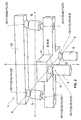
- a first embodiment (pin formation) of the second arrangement described above is shown in various representations.
- the die plate 42 which has an approximately rectangular plan.
- the die plate 42 has at four diametrically opposite corner regions of its rectangular-like outline each have a sleeve-like formation 42a, 42b, 42c, 42d, each with a cylinder bore whose cylinder axis extends parallel to the Hubachse ZZ.
- the die plate 42 On its upper side, the die plate 42 has a substantially flat surface 42e to which application specific tools can be mounted. For this purpose, numerous mounting holes in the surface 42e are provided.
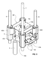
- the die plate 42 is supported on four cylindrical guides 5, 6, 7, 8, as best shown in Figs Fig. 8 sees. These guides 5, 6, 7, 8 extend parallel to each other in the Z-direction parallel to the stroke axis ZZ. As a result, the die plate 42 is displaceable along the lifting axis ZZ.
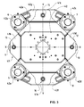
- FIG. 3 In the top view of Fig. 3 can also be seen the intermediate member 41 which is disposed below the die plate 42 and partially covered by this. In the hidden area, the outline of the intermediate member 41 is shown in dashed lines.
- the intermediate member 41 has in its plan view outline four lobes 41 a, 41 b, 41 c, 41 d, each having a vertical through hole or a vertical bore. In this vertical through hole and through this extends in each case one of four connecting members 11, 12, 14, 15th
- the location of the connecting member 11 and the connecting member 12 in the plan view are on a in the horizontal direction, ie orthogonal to the lifting axis ZZ extending first straight line XX.
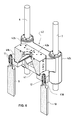
- the connecting member 11 extends through the vertical hole of the bulge 41 b of the intermediate member 41 therethrough and is at its lower end to the Drive means 9, as best seen in the side view of Fig. 4 or in the perspective view of Fig. 6 with the section along the vertical plane XX (see Fig. 3 ) recognizes.
- the link 12 extends through the vertical hole of the bulge 41 d of the intermediate member 41 and is secured at its lower end to the drive means 10, as is also best in Fig. 4 recognizes.
- a bulge 42f and a bulge 42g of the die plate 42 which also each have a vertical through hole or a vertical bore.
- one of the two connecting members 14, 15 extends in this vertical through hole and through it.
- the location of the connecting member 14 and the connecting member 15 in plan view are on a in the horizontal direction, ie orthogonal to the Hubachse ZZ extending and orthogonal to the first line XX second straight line YY.
- the link 14 extends through the vertical hole of the recess 42 f of the die plate 42 and is secured at its lower end to the recess 41 a of the intermediate member 41, as best seen in the side view of Fig. 5 or in the perspective of Fig. 7 with the section along the vertical plane YY (see Fig. 3 ) recognizes.
- the connecting member 15 extends through the vertical hole of the bulge 42 g of the die plate 42 and is secured at its lower end to the bulge 41 c of the intermediate member 41, as is also best in Fig. 5 recognizes.
- Fig. 9 is an exploded perspective view of the in Fig. 3 to Fig. 8 shown elements shown.
- the screws S are each tensioned under tension, ie elastically elongated in the Z direction, while the annular disc R and the sleeve H each under pressure, ie are shortened elastically in the Z direction.
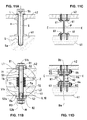
- Fig. 10A is a vertical section of a connector shown in more detail 11 or 12 according to a first variant (single screw with sleeve) of the first embodiment (pin formation) shown, which is arranged in a region between the drive means 9 and the drive means 10 and the intermediate member 41.
- the screw S protrudes through a through hole L in the intermediate member 41 and through a sleeve H and is screwed with its lower end or tip Sa in a threaded hole G at the upper end of the drive means 9 and 10, while the upper end or the head Sb of the screw rests with its shoulder on the annular disc R, which in turn rests on the upper surface of the intermediate member 41 surrounding the through hole L.
- the sleeve H has at its lower end and at its upper end in each case a flange-like expansion Ha or Hb, wherein the lower flange-like expansion Ha rests on a threaded bore G surrounding upper surface of the drive means 9 and 10 and the upper flange-like expansion Hb a lower surface of the intermediate member 41 surrounding the through-hole L abuts.
- the thus formed two units of tensioned screw S, strained annular disc R and strained sleeve H are clamped between the drive means 9 and 10 and the intermediate member 41 and form the first flexible connecting member 11 and the second flexible connecting member 12th
- Fig. 11A is a vertical section of a detailed illustrated connecting member 14 or 15 according to the first variant (single screw with sleeve) of the first embodiment (pin formation) shown in a Region between the intermediate member 41 and the die plate 42 is arranged.
- the screw S protrudes through a through hole L in the intermediate plate 42 and through the sleeve H and is screwed with its lower end or tip Sa into a threaded hole G at an upper side of the intermediate member 41, while the head Sb of the screw with his Shoulder rests on the annular disc R, which in turn rests on the through hole L surrounding upper surface of the die plate 42.
- the sleeve H has at its lower end and at its upper end in each case the flange-like expansion Ha or Hb, wherein the lower flange-like expansion Ha rests against the threaded bore G surrounding upper side of the intermediate member 41 and the upper flange-like expansion Hb at a through hole L surrounding lower surface of the die plate 42 abuts.
- the thus formed two units of tensioned screw S, tensioned washer R and strained sleeve H are clamped between the intermediate member 41 and the die plate 42 and form the third flexible connecting member 14 and the fourth flexible connecting member 15 of the second arrangement (multipoint flexi-storage /Suspension).
- the third link 13 of the first arrangement (one-point flexi storage / suspension) in the Fig. 11A have described structure. Conveniently, however, it would be somewhat larger than the first connecting member 11 and the second connecting member 12 of this first arrangement.
- the flexibility of in Fig. 10A and in Fig. 11A shown pin-like connecting members 11, 12 and 13, 14, 15 can be adjusted for example by the length and / or the wall thickness of the sleeve H and by the choice of the material of the sleeve H.
- An enlargement / reduction of the length of the sleeve H leads to an increase / decrease in the flexibility of the connecting member.
- An enlargement / reduction of the wall thickness of the sleeve H leads to a reduction / enlargement of the flexibility of the connecting member.
- An enlargement / reduction of the modulus of elasticity of the material of the sleeve H leads to an enlargement / reduction of the flexibility of the connecting member.
- Fig. 10B is a vertical section of a connector shown in more detail 11 or 12 according to a second variant (twin screw with disc spring) of the first embodiment (pin formation) shown, which is arranged in a region between the drive means 9 and the drive means 10 and the intermediate member 41.
- a first screw S1 protrudes through a first through hole L1 in the intermediate member 41 and through a cup spring stack T and protrudes with its lower end S1 a in a second through hole L2 in a mounting region of the drive means 9 and 10, while the upper end or the head S1b of the first screw S1 rests with its shoulder on a first annular disc R1, which in turn rests on a second annular disc R2, which finally rests on the upper surface of the intermediate member 41 surrounding the first through hole L1 in an annular recess.
- a second screw S2 protrudes into the second through-hole L2 in the fastening region of the drive means 9 and 10.
- the upper end S2a of the second screw S2 is sleeve-like and has inside the sleeve portion S2a an internal thread that has a complementary external thread on the cylindrical Tip S1a of the first screw S1 is engaged, while the lower end or the head S2b of the second screw S2 abuts with its shoulder on a lock nut M, which in turn bears against a third annular disc R3, which in turn bears against a fourth annular disc R4, which finally abuts on the second through hole L2 surrounding lower surface of the mounting portion of the drive means 9 and 10 in an annular recess.
- the plate spring stack T has a similar function as the sleeve H of the first variant (see Fig. 10A ).
- the plate spring stack T has at its lower end a lower plate spring Ta and at its upper end an upper plate spring Tb, each with its large annular surface, the lower and upper face of the plate spring stack T form (similar to the flange-like expansion Ha or Hb of Sleeve H in Fig. 10A ), wherein the lower plate spring Ta rests on an upper surface of the drive means 9 and 10 surrounding the second through hole L2, and the upper plate spring Tb abuts a lower surface of the intermediate member 41 surrounding the first through hole L1.
- the first screw S1 and the second screw S2 are screwed together in the assembled state, wherein the plate spring stack T is compressed in the Z direction.
- the two units thus formed each contain the two strained screws S1, S2, the four strained annular discs R1, R2, R3, R4, the lock nut M and the tensioned plate spring stack T and are clamped between the drive means 9 and 10 and the intermediate member 41. They form the first flexible connecting member 11 and the second flexible connecting member 12.
- the contact area 81 between the first annular disc R1 and the second annular disc R2 and the contact area 82 between the third annular disc R3 and the fourth annular disc R4 are each formed by a pair of contacting spherical surfaces, namely a concave spherical surface on the first annular disc R1 and a convex spherical surface on the second annular disc R2, both of which have the same radius of curvature with respect to the common center Z of an imaginary spherical surface, which in FIG Fig. 10B is indicated as a dashed circle.
- a first annular gap 71 is present between the inner surface of the hole of the second annular disk R2 and the outer surface of the first screw S1 and between the inner surface of the first through hole L1 of the intermediate member 41 and the outer surface of the first screw S1.
- a second annular gap 72 is also present between the inner surface of the hole of the fourth annular disc R4 and the outer surface of the second screw S2 and between the inner surface of the second through-hole L2 in the drive means 9 and 10 and the outer surface of the second screw S2.
- the plate spring stack T When mounting the connecting members 11, 12 thus formed, the plate spring stack T is compressed, whereby the respective adjacent spherical surfaces of the first annular disc R1 and the second annular disc R2 and the third annular disc R3 and the fourth annular disc R4 are pressed against each other.
- the flexibility of the so formed Connecting links 11, 12 (see Fig. 4 and Fig. 6 ) is based on the play in the gap regions 71, 72, on the elastic deformability of the diaphragm spring stack T and on the possibility of sliding together the first and second annular disc R1, R2 in the first contact region 81 as well as the possibility of sliding together the third and the fourth annular disc R3, R4 in the second contact region 82.
- Fig. 11 B is a vertical section of a more detailed illustrated link 14 or 15 according to the second variant (double screw with plate spring) of the first embodiment (pin formation), which is arranged in a region between the intermediate member 41 and the die plate 42.
- the first screw S1 protrudes through a first through hole L1 in the die plate 42 and through a plate spring stack T and protrudes with its lower end S1a in a second through hole L2 in the mounting region of the intermediate member 41, while the upper end or the head S1 b of the first screw S1 rests with its shoulder on the first annular disc R1, which in turn rests on the second annular disc R2, which finally rests on the first through hole L1 surrounding the upper surface of the die plate 42 in an annular recess.
- the second screw S2 protrudes into the second through hole L2 in the attachment region of the intermediate member 41.
- the upper end S2a of the second screw S2 is sleeve-shaped and has inside the sleeve portion S2a an internal thread with a complementary external thread on the cylindrical tip S1a first screw S1 is engaged while the lower end or the head S2b of the second screw S2 abuts with its shoulder on the lock nut M, which in turn bears against the third annular disc R3, which in turn bears against the fourth annular disc R4, the finally on the lower surface of the attachment portion of the intermediate member 41 surrounding the second through hole L2 abuts in an annular recess.
- the plate spring stack T has a similar function as the sleeve H of the first variant (see Fig. 11A ).
- the plate spring stack T has at its lower end a lower plate spring Ta and at its upper end an upper plate spring Tb, each with its large annular surface, the lower and the upper end face of the Disc spring stack T form (similar to the flange-like expansion Ha or Hb of the sleeve H in Fig. 11A ), wherein the lower plate spring Ta rests on an upper surface of the intermediate member 41 surrounding the second through hole L2, and the upper plate spring Tb abuts against a lower surface of the female plate 42 surrounding the first through hole L1.
- the first screw S1 and the second screw S2 are screwed together in the assembled state, wherein the plate spring stack T is compressed in the Z direction.
- the two units thus formed each contain the two tensioned screws S1, S2, the four strained annular discs R1, R2, R3, R4, the lock nut M and the tensioned plate spring stack T and are clamped between the intermediate member 41 and the die plate 42. They form the third flexible connecting member 14 and the fourth flexible connecting member 15 of the second arrangement (multi-point flexi-storage / suspension).
- the third link 13 of the first arrangement (one-point flexi storage / suspension) in the Fig. 11B have described structure. Conveniently, however, it would be somewhat larger than the first connecting member 11 and the second connecting member 12 of this first arrangement.
- the contact area 81 between the first annular disk R1 and the second annular disk R2 and the contact area 82 between the third annular disk R3 and the fourth annular disk R4 are each formed by a pair of contacting spherical surfaces through the concave spherical surface on the first annular disk R1 and the convex spherical surface on the second annular disc R2, both of which have the same radius of curvature with respect to the common center Z of an imaginary spherical surface, which in FIG Fig. 11B is indicated as a dashed circle.
- the first gap 71 is present between the inner surface of the hole of the second annular disc R2 and the outer surface of the first screw S1 and between the inner surface of the first through hole L1 of the die plate 42 and the outer surface of the first screw S1.
- the second gap 72 is present between the inner surface of the hole between the fourth Ring disc R4 and the outer surface of the second screw S2 and between the inner surface of the second through-hole L2 in the intermediate member 41 and the outer surface of the second screw S2, the second gap 72 is present.
- the plate spring stack T When assembling the thus formed connecting members 14, 15, the plate spring stack T is compressed, whereby the respective adjacent spherical surfaces of the first annular disc R1 and the second annular disc R2 and the third annular disc R3 and the fourth annular disc R4 are pressed together.
- the flexibility of the links 14, 15 thus formed is based on the play in the gap regions 71, 72, on the elastic deformability of the diaphragm spring stack T and on the possibility of sliding together the first and second annular disc R1, R2 in the first contact region 81 as well as the possibility of sliding together the third and the fourth annular disc R3, R4 in the second contact region 82.
- the flexibility of in Fig. 10B and in Fig. 11B illustrated pin-like connecting members 11, 12 and 13, 14, 15 can be adjusted for example by the total length of the two screws S1 and S2 and / or the wall thickness of the sleeve portion S2a and by the choice of the material of the screws S1 and S2.
- An enlargement / reduction of the total length of the screws S1 and S2 leads to an increase / decrease in the flexibility of the connecting member.
- An enlargement / reduction of the wall thickness of the sleeve portion S2a leads to a reduction / enlargement of the flexibility of the connecting member.
- An enlargement / reduction of the modulus of elasticity of the material of the screws S1 and S2 thereby leads to an enlargement / reduction of the flexibility of the connecting member.
- the intermediate member 41 from the in Fig. 10B shown position is tilted relative to the drive means 9 or 10, takes place up to a maximum value of the tilting moment an elastic deformation of the screws formed by the screws S1 and S2 and by the plate spring stack T flexible Verbingsglieder 11, 12.
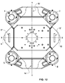
- FIG. 10A . Fig. 11A . Fig. 10B . Fig. 11B illustrated and described pin-like first embodiment (see. Fig. 3 ) of the flexible connecting members 11, 12, 14, 15, these can also be designed like a sheet, as shown in Fig. 12 is shown, in which these sheet-like flexible connecting members 11 ',, 12', 14 ', 15' in section along a horizontal sectional plane EE (see 10C, 10D . 11C, 11D ) are shown.
- the illustrations in Fig. 10A . Fig. 11A . Fig. 10B . Fig. 11B Then vertical sections would be orthogonal to the plane of the respective sheet-like connecting member, the leaf level would then extend in a plane parallel to the lifting axis ZZ.
- the sleeve H in Fig. 10A and Fig. 11A would then be replaced by two U-profiles, one of which is open to the left and the other is open to the right. That is, the legs of one U-profile extend to the left, and the legs of the other U-profile extend to the right, while the base of the two U-profiles by fastening means (not shown) to the screws or pins S and S1, respectively would be attached.
- Fig. 10C is a vertical section of a detailed illustrated link 11 'or 12' according to a first variant (screwed H-profile) of the second embodiment (sheet) shown, which is arranged in a region between the drive means 9 and the drive means 10 and the intermediate member 41.
- an H-profile P whose longitudinal axis extends orthogonal to the lifting axis ZZ, between the drive member 9 and 10 and the intermediate member 41 is arranged such that two of the four legs of the H-profile to the left and two of these four legs of the H. Profiles to the right.
- the lower end Pa of the H-profile P rests on an upper surface of the drive means 9 and 10, respectively, while the upper end Pb of the H-profile P abuts a lower surface of the intermediate member 41.
- the two resting on the drive means 9 and 10 and the lower end Pa of the H-profile forming two legs are each secured with a fastening screw 61 which extends through a hole in the respective leg and screwed into a threaded hole in the drive means 9 and 10 respectively is.
- the two adjoining the intermediate member 41 and the upper end Pb of the H-profile forming two legs are also each secured with a fastening screw 61 which extends through a hole in the respective leg and is screwed into a threaded hole in the intermediate member 41.
- the plane EE is the sectional plane along which the links 11 'and 12' in Fig. 12 are shown cut.
- Fig. 11C is a vertical section of a detailed illustrated connecting member 14 'or 15' according to the first variant (screwed H-profile) of the second embodiment (sheet) shown, which is arranged in a region between the intermediate member 41 and the die plate 42.
- the H-profile P whose longitudinal axis extends again orthogonal to the lifting axis ZZ, between the intermediate member 41 and the die plate 42 is arranged such that two of the four legs of the H-profile to the left and two of these four legs of the H-profile extend to the right.
- the lower end Pa of the H-profile P rests on an upper surface of the intermediate member 41, while the upper end Pb of the H-profile P abuts a lower surface of the die plate 42.
- the two resting on the intermediate member 41 and the lower end Pa of the H-profile forming two legs are each secured with a fastening screw 61 which extends through a hole in the respective leg and is screwed into a threaded bore in the intermediate member 41.
- the two adjoining the die plate 42 and the upper end Pb of the H-profile forming two legs are also each secured with a fastening screw 61 which extends through a hole in the respective leg and is screwed into a threaded bore in the die plate 42.
- the plane EE is the sectional plane along which the links 14 'and 15' in Fig. 12 are shown cut.
- the third link 13 of the first arrangement (one-point flexi storage / suspension) in the Fig. 11C have described structure. Expediently, however, it would be dimensioned somewhat larger than the first connecting member 11 'and the second connecting member 12' of this first arrangement.
- Fig. 10D is a vertical section of a detailed illustrated connecting member 11 'or 12' according to a second variant (screwed leaf spring) of the second embodiment (sheet) shown, which is arranged in a region between the drive means 9 and the drive means 10 and the intermediate member 41.
- a leaf spring B whose longitudinal axis extends orthogonal to the lifting axis ZZ, between the drive member 9 and 10 and the intermediate member 41 is arranged such that the leaf plane extends parallel to the lifting axis ZZ.
- the lower end Ba of the leaf spring B rests on an upper surface of the drive means 9 and 10, respectively, while the upper end Bb of the leaf spring B abuts a lower surface of the intermediate member 41.
- the lower end or the lower edge Ba of the leaf spring B is fixed by means of two clamping strips K1, K2 to the drive means 9 and 10 respectively.
- these two terminal strips K1, K2 are respectively screwed by means of fastening screws 62 to the drive means 9 and 10 respectively.
- a further fastening screw 63 extends in the transverse direction through a respective through hole in the terminal block K1, in the lower end Ba of the leaf spring B and in the terminal block K2, said fastening screw 63 is screwed at its tip with a fastening nut 64 and tightened.
- the upper end or the upper edge Bb of the leaf spring B is fixed to the intermediate member 41 by means of two clamping strips K3, K4.
- these two terminal strips K3, K4 are respectively screwed by means of fastening screws 62 to the intermediate member 41.
- a further fastening screw 63 extends in the transverse direction through a respective through hole in the terminal block K3, in the upper end Bb of the leaf spring B and in the terminal block K4, and this fastening screw 63 is screwed at its tip with a fastening nut 64 and tightened .
- the plane EE is the sectional plane along which the links 11 'and 12' in Fig. 12 are shown cut.
- Fig. 11D is a vertical section of a detailed illustrated connecting member 14 'or 15' according to the second variant (screwed leaf spring) of the second embodiment (sheet form) is shown, which is arranged in a region between the intermediate member 41 and the die plate 42.
- the leaf spring B whose longitudinal axis extends orthogonal to the lifting axis ZZ, arranged between the intermediate member 41 and the die plate 42 such that the sheet plane extends parallel to the lifting axis ZZ.
- the lower end Ba of the leaf spring B rests on an upper surface of the intermediate member 41, while the upper end Bb of the leaf spring B abuts a lower surface of the die plate 42.
- the lower end or the lower edge Ba of the leaf spring B is fixed to the intermediate member 41 by means of two clamping strips K1, K2.
- these two terminal strips K1, K2 are respectively screwed by means of fastening screws 62 to the intermediate member 41.
- a further fastening screw 63 extends in the transverse direction through a respective through hole in the terminal block K1, in the lower end Ba of the leaf spring B and in the terminal block K2, said fastening screw 63 is screwed at its tip with a fastening nut 64 and tightened.
- the upper end or the upper edge Bb of the leaf spring B is fixed to the die plate 42 by means of two clamping strips K3, K4.
- these two terminal strips K3, K4 are respectively screwed by means of fastening screws 62 to the die plate 42.
- a further fastening screw 63 extends in the transverse direction through a respective through hole in the terminal block K3, in the upper end Bb of the leaf spring B and in the terminal block K4, and this fastening screw 63 is screwed at its tip with a fastening nut 64 and tightened .
- the plane EE is the sectional plane along which the links 14 'and 15' in Fig. 12 are shown cut.
- the third link 13 of the first arrangement (one-point flexi storage / suspension) in the Fig. 11D have described structure. Expediently, however, it would be dimensioned somewhat larger than the first connecting member 11 'and the second connecting member 12' of this first arrangement.
- Fig. 12 is one of the Fig. 3 similar plan view of the detailed illustrated elements of the second arrangement according to the second embodiment (see Fig. 10C . Fig. 11C respectively. Fig. 10D . Fig. 11D ), wherein the respective connecting members are shown cut along a horizontal plane EE. While the pin-like connecting members 11, 12, 14, 15 of the first embodiment ( Fig. 3 ) are flexible in all directions of the plane XY, the sheet-like connecting links 11 ', 12', 14 ', 15' of this second embodiment ( Fig. 12 ) are practically flexible only for deflections in the X direction while having virtually no flexibility in the Y direction.
- both the first embodiment of the Fig. 3 with only pin-like connecting members 11, 12, 14, 15 and the second embodiment of the Fig. 12 with only leaf-like connecting members 11 ', 12', 14 ', 15' a torque-free (tilting moment) force introduction into the Die plate 42 in the event that the two drive means 9 and 10 have a difference between their along the press stroke axis ZZ extending paths.
Abstract
Description
Die Erfindung bezieht sich auf eine Pulverpresse zur Herstellung eines Presslings aus einem pulverförmigen Material. Eine solche Pulverpresse hat einen Rahmen, eine Stempelanordnung und einer Matrizenanordnung. Letztere definiert einen Formhohlraum, in den das pulverförmige Material eingefüllt werden kann, woraufhin zur Formung des Presslings die Stempelanordnung und die Matrizenanordnung entlang einer Pressen-Vertikalachse relativ zueinander bewegt und gegeneinander gepresst werden können.The invention relates to a powder press for producing a compact of a powdery material. Such a powder press has a frame, a punch assembly and a die assembly. The latter defines a mold cavity into which the powdered material can be filled, whereupon, to form the compact, the punch assembly and die assembly can be moved relative to one another along a press vertical axis and pressed against each other.
Der Antrieb der Matrizenanordnung oder der Stempelanordnung erfolgt in der Regel über zwei zueinander parallel zur Vertikalachse der Presse wirkende Antriebe mit jeweils einem Servomotor. Die beiden Servomotoren arbeiten im Master-Slave-Betrieb, um eine weitgehend synchrone Verfahrbewegung der beiden parallelen Antriebe entlang bzw. parallel zur Vertikalachse zu gewährleisten.The drive of the die assembly or the punch assembly is usually via two mutually parallel to the vertical axis of the press acting drives, each with a servo motor. The two servomotors work in master-slave mode to ensure a largely synchronous movement of the two parallel drives along or parallel to the vertical axis.
Es ist äusserst wichtig, dass die Verfahrbewegung der beiden parallelen Antriebe synchron verläuft. Ansonsten könnten Schiefstellungen von entlang der Pressen-Vertikalachse verfahrbarer und geführter Teile der Presse auftreten. Je nach Bauart der Presse betrifft dies die Matrizenplatte und/oder die Stempelplatte, die entlang mehrerer zueinander paralleler vertikaler Führungen geführt sind. Würde hier zwischen den beiden zueinander parallelen Antrieben eine grössere Differenz ihrer Verfahrwege auftreten, könnte das (an der Matrizenplatte und/oder an der Stempelplatte) montierte Werkzeug beschädigt werden. Im schlimmsten Fall können sogar die vertikalen Führungen der Matrizenplatte und/oder der Stempelplatte sowie der Antriebe beschädigt werden.It is extremely important that the movement of the two parallel drives is synchronous. Otherwise, misalignments could occur of displaceable and guided parts of the press along the press vertical axis. Depending on the design of the press, this relates to the die plate and / or the stamp plate, which are guided along a plurality of mutually parallel vertical guides. If a greater difference between their travel paths would occur between the two drives parallel to one another, the tool mounted on the die plate and / or on the stamp plate could be damaged. In the worst case, even the vertical guides of the die plate and / or the stamp plate and the drives can be damaged.
Um hier vorzubeugen, sind verschiedene Massnahmen im Bereich Software und elektrischer Hardware bekannt und werden mit Erfolg eingesetzt. Dadurch können auch in Sonderbetriebsarten und bei besonderen Zuständen der Presse, wie z.B. Sofort-Stopp, Not-Aus, Stromausfall, etc., die Antriebe kontrolliert stillgesetzt werden.To prevent this, various measures in the field of software and electrical hardware are known and are used successfully. As a result, even in special modes and in special conditions of the press, such as immediate stop, emergency stop, power failure, etc., the drives are stopped in a controlled manner.
Dennoch bleibt ein geringes Restrisiko übrig. Wird z.B. die für den Master-Slave-Betrieb notwendige Kommunikationsverbindung zwischen den beiden Antriebsreglern gekappt, besteht die Gefahr, dass die beiden Servomotoren nicht mehr synchron arbeiten. Im schlimmsten Fall würden dabei die beiden Servomotoren bis zum Stillsetzen gegeneinander arbeiten. Dies würde mit grosser Wahrscheinlichkeit zu erheblichen Schäden am Werkzeug und evtl. an der Presse führen.Nevertheless, a small residual risk remains. If e.g. If the communication connection between the two drive controllers required for master-slave operation is cut off, there is a risk that the two servomotors will no longer work synchronously. In the worst case, the two servomotors would work against each other until they stopped. This would most likely lead to considerable damage to the tool and possibly to the press.
Der Erfindung liegt die Aufgabe zugrunde, dieses Restrisiko weitgehend zu eliminieren.The invention has for its object to largely eliminate this residual risk.
Diese Aufgabe wird gelöst mittels einer Pulverpresse zur Herstellung eines Presslings aus einem pulverförmigen Material, mit einem Rahmen, einer Stempelanordnung und einer Matrizenanordnung, welche einen Formhohlraum definiert, in den das pulverförmige Material einfüllbar ist und danach zur Formung des Presslings die Stempelanordnung und die Matrizenanordnung entlang einer Pressen-Vertikalachse Z-Z relativ zueinander bewegbar und gegeneinander pressbar sind, wobei erfindungsgemäss
- a) die Matrizenanordnung ein mit zwei parallel entlang der Vertikalachse Z-Z wirkenden Antriebsmitteln verbundenes Zwischenglied und eine an Führungsmitteln entlang der Hubrichtung bzw. Vertikalachse Z-Z geführte und mit dem Zwischenglied verbundene Matrizenplatte aufweist; und/oder a') die Stempelanordnung ein mit parallel entlang der Vertikalachse Z-Z wirkenden Antriebsmitteln verbundenes weiteres Zwischenglied und eine an Führungsmitteln entlang der Hubrichtung bzw. Vertikalachse Z-Z geführte und mit dem Zwischenglied verbundene Stempelplatte aufweist;
- b) das Zwischenglied mit einem ersten Antriebsmittel mittels eines ersten flexiblen Verbindungsmittels verbunden ist und mit einem zweiten Antriebsmittel mittels eines zweiten flexiblen Verbindungsmittels verbunden ist, wobei das erste Verbindungsmittel sowie das zweite Verbindungsmittel auf einer zur Pressen-Vertikalachse Z-Z orthogonalen ersten Geraden X-X angeordnet sind; und
- c) das Zwischenglied und die Matrizenplatte bzw. das weitere Zwischenglied und die Stempelplatte mittels eines dritten flexiblen Verbindungsmittels miteinander verbunden sind, das auf einer zur Pressen-Hubrichtung bzw. Vertikalachse Z-Z orthogonalen und zur ersten Geraden X-X orthogonalen zweiten Geraden Y-Y äquidistant zu dem ersten flexiblen Verbindungsmittel und dem zweiten flexiblen Verbindungsmittel derart angeordnet ist, dass die durch das dritte flexible Verbindungsmittel übertragene resultierende Zugkraft oder Schubkraft in einem Punkt auf einer durch den Schwerpunkt der Matrizenplatte bzw. der Stempelplatte verlaufenden vertikalen Geraden in die Matrizenplatte bzw. in die Stempelplatte eingeleitet wird.
- a) the die assembly has an associated with two parallel along the vertical axis ZZ drive means connected intermediate member and guided on guide means along the lifting direction or vertical axis ZZ and connected to the intermediate plate die plate; and / or a ') the punch arrangement has a further intermediate member connected to drive means acting parallel along the vertical axis ZZ and a stamp plate guided on guide means along the stroke direction or vertical axis ZZ and connected to the intermediate member;
- b) the intermediate member is connected to a first drive means by means of a first flexible connection means and is connected to a second drive means by means of a second flexible connection means, wherein the first connection means and the second connection means are arranged on a first straight line XX orthogonal to the press vertical axis ZZ; and
- c) the intermediate member and the die plate or the further intermediate member and the punch plate are interconnected by means of a third flexible connecting means, which on a press-lifting direction or Vertical axis ZZ orthogonal and orthogonal to the first straight line XX second straight line YY is arranged equidistant to the first flexible connection means and the second flexible connection means such that the resultant by the third flexible connection means resulting tensile force or thrust force at a point on one of the center of gravity of the die plate and the stamp plate extending vertical straight lines in the die plate or in the die plate is initiated.
Besonders vorteilhaft ist es, wenn die praktisch nur in der vertikalen Richtung erfolgende Krafteinleitung durch das dritte flexible Verbindungsmittel im Schwerpunkt der Matrizenplatte bzw. der Stempelplatte erfolgt.It is particularly advantageous if the introduction of force takes place practically only in the vertical direction by the third flexible connection means in the center of gravity of the die plate or the stamp plate.
Dieser erfindungsgemässe Aufbau gewährleistet, dass selbst bei einer aus irgendeinem Grund auftretenden Differenz zwischen dem sich entlang der Pressen-Hubachse Z-Z (z.B. Vertikalrichtung) erstreckenden Verfahrweg des ersten Antriebsmittels und des dazu parallel wirkenden zweiten Antriebsmittels die Zugkraft oder Schubkraft mit einem sehr geringen Kippmoment oder praktisch ohne Kippmoment in die Matrizenplatte bzw. in die Stempelplatte eingetragen wird.This construction according to the invention ensures that even with a difference between the travel path of the first drive means extending along the press stroke axis ZZ (eg vertical direction) and the second drive means acting in parallel therewith, the tractive force or thrust force with a very low tilting moment or practically is entered without tilting moment in the die plate or in the stamp plate.
Bei der erfindungsgemässen Pulverpresse erfolgt die Krafteinleitung von den beiden parallelen Antrieben in die Matrizenplatte und/oder in die Stempelplatte je nach Aufbau der Presse über ein Matrizenplatten-Zwischenglied in die Matrizenplatte und/oder über ein Stempelplatten-Zwischenglied in die Stempelplatte. Die beiden parallelen Antriebe, die Matrizenplatte und/oder die Stempelplatte sind dabei starre Gebilde, die aufgrund ihrer Geometrie, wie z.B. relativ dicke Ausbildung der Platte, Versteifungsrippen an der Platte, etc., sowie aufgrund des Plattenmaterials, wie z.B. Stahl, unter Lasteinwirkung nur eine geringe Verformung erfahren.In the case of the powder press according to the invention, the introduction of force from the two parallel drives into the die plate and / or into the die plate takes place via a die plate intermediate member into the die plate and / or via a stamp plate intermediate member into the die plate, depending on the structure of the press. The two parallel drives, the die plate and / or the stamp plate are rigid structures, which due to their geometry, such as. relatively thick formation of the plate, stiffening ribs on the plate, etc., as well as due to the plate material, e.g. Steel, experienced under load only a small deformation.
Im Gegensatz dazu ermöglichen die flexiblen Verbindungsmittel, die einerseits zwischen jedem der beiden Antriebe und dem Zwischenglied angeordnet sind und andererseits zwischen einem Zwischenglied (Matrizenplatten-Zwischenglied) und der Matrizenplatte und/oder zwischen einem Zwischenglied (Stempelplatten-Zwischenglied) und der Stempelplatte angeordnet sind, eine Verformung, insbesondere eine Verbiegung der flexiblen Verbindungsmittel.In contrast, the flexible connecting means, on the one hand between each of the two drives and the intermediate member are arranged and on the other hand between an intermediate member (die plate intermediate member) and the die plate and / or between an intermediate member (stamp plate intermediate member) and the die plate are arranged, a deformation, in particular a bending of the flexible connection means.
Dadurch kann eine Differenz zwischen dem sich entlang der Pressen-Hubachse Z-Z (z.B. Vertikalrichtung) erstreckenden Verfahrweg des ersten Antriebs und des dazu parallel wirkenden zweiten Antriebs unter Verformung des ersten flexiblen Verbindungsmittels und des zweiten flexiblen Verbindungsmittels auf das Zwischenglied übertragen werden. Dabei wird das Zwischenglied um eine Drehachse gekippt, die sich einerseits orthogonal zu der ersten Geraden X-X erstreckt, welche durch das erste flexible Verbindungsmittel und durch das zweite flexible Verbindungsmittel verläuft, und sich andererseits orthogonal zur Hubrichtung Z-Z erstreckt.Thereby, a difference between the travel of the first drive and the second drive parallel thereto along the press stroke axis Z-Z (e.g., vertical direction) can be transmitted to the link while deforming the first flexible connection means and the second flexible connection means. In this case, the intermediate member is tilted about an axis of rotation which extends on the one hand orthogonal to the first straight line X-X, which extends through the first flexible connection means and through the second flexible connection means, and on the other hand extends orthogonal to the stroke direction Z-Z.
Die Drehachse bzw. Kippachse des Zwischenglieds erstreckt sich parallel zu der zweiten Geraden Y-Y, auf der das dritte flexible Verbindungsmittel äquidistant zu dem ersten flexiblen Verbindungsmittel und dem zweiten flexiblen Verbindungsmittel angeordnet ist. Das dabei von dem Zwischenglied über das dritte flexible Verbindungsmittel auf die Matrizenplatte bzw. auf die Stempelplatte übertragene Kippmoment ist viel kleiner als das Kippmoment, das auf die Matrizenplatte bzw. auf die Stempelplatte übertragen würde, wenn die beiden Antriebe mit einer Verfahrweg-Differenz direkt auf die Matrizenplatte bzw. auf die Stempelplatte einwirken würden.The axis of rotation or tilt axis of the intermediate member extends parallel to the second straight line Y-Y, on which the third flexible connection means is arranged equidistant from the first flexible connection means and the second flexible connection means. The case of the intermediate member via the third flexible connection means on the die plate or on the stamp plate transmitted tilting moment is much smaller than the overturning moment that would be transmitted to the die plate or on the stamp plate, if the two drives with a travel difference directly on would act on the die plate or on the stamp plate.
Dadurch werden Schiefstellungen der entlang mehrerer zueinander paralleler Führungen geführten Matrizenplatte und/oder Stempelplatte entscheidend verringert, wodurch Beschädigungen des Werkzeugs oder der Führungen der Matrizenplatte und/oder der Stempelplatte sowie der Antriebe wirkungsvoll verhindert werden.As a result, misalignments along a plurality of mutually parallel guides guided die plate and / or stamp plate are significantly reduced, causing damage to the tool or the guides of the die plate and / or the stamp plate and the drives are effectively prevented.
Die Gerade X-X kann als die Gerade definiert werden, entlang welcher die beiden Antriebe angeordnet sind, oder etwas genauer gesagt, die Gerade, auf welcher die Berührungspunkte des ersten flexiblen Verbindungsmittels und des zweiten flexiblen Verbindungsmittels mit dem Zwischenglied liegen. Die zur Gerade X-X orthogonale Gerade Y-Y kann als die Gerade definiert werden, auf welcher oder entlang welcher das dritte flexible Verbindungsmittel angeordnet ist, oder etwas genauer gesagt, die Gerade, auf welcher die Berührungspunkte des dritten flexiblen Verbindungsmittels mit der Matrizenplatte bzw. mit der Stempelplatte liegen.The line XX can be defined as the straight line along which the two drives are arranged, or more precisely, the straight line on which the points of contact of the first flexible connection means and the second flexible connection means lie with the intermediate member. The straight line YY orthogonal to the line XX can be defined as the straight line on which or along which the third line is arranged flexible connecting means, or more precisely, the straight line on which lie the points of contact of the third flexible connection means with the die plate and with the stamp plate.
Vorzugsweise sind die Positionen der ersten Geraden X-X, der zweiten Geraden Y-Y und der dazu parallelen Kippachse des Zwischenglieds in der Z-Richtung identisch oder nahezu identisch. Die Z-Position der Zwischenglied-Kippachse liegt typischerweise, aber nicht notwendigerweise, zwischen der Z-Position der Geraden X-X und der Z-Position der Geraden Y-Y. Diese Massnahme bewirkt, dass beim Kippen des Zwischenglieds als Reaktion auf eine Verfahrweg-Differenz zwischen den beiden Antrieben das dritte flexible Verbindungsmittel praktisch nicht aus seiner äquidistanten Position zwischen dem ersten flexiblen Verbindungsmittel und dem zweiten flexiblen Verbindungsmittel wegbewegt wird. Zweckmässgerweise sind die Gerade Y-Y mit dem dritten flexiblen Verbindungsmittel und die Kippachse innerhalb einer relativ kleinen Bandbreite der Z-Position entlang der Hubachse Z-Z um die Z-Position der Geraden X-X angeordnet. Vorzugsweise ist diese Bandbreite ΔZ, d.h. dieses Z-Intervall kleiner als die Hälfte, noch bevorzugter kleiner als ein Viertel, des X-Abstands zwischen dem ersten flexiblen Verbindungsmittel und dem zweiten flexiblen Verbindungsmittel entlang der Geraden X-X.Preferably, the positions of the first straight line X-X, the second straight line Y-Y and the tilting axis of the intermediate link parallel thereto in the Z direction are identical or nearly identical. The Z-position of the link tilt axis is typically, but not necessarily, between the Z position of the line X-X and the Z position of the line Y-Y. This measure has the effect that, when the intermediate member is tilted in response to a travel distance difference between the two drives, the third flexible connection means is practically not moved away from its equidistant position between the first flexible connection means and the second flexible connection means. Expediently, the straight line Y-Y with the third flexible connecting means and the tilting axis are arranged within a relatively small bandwidth of the Z position along the lifting axis Z-Z about the Z position of the straight line X-X. Preferably, this bandwidth is ΔZ, i. this Z-interval is less than half, more preferably less than a quarter, of the X-distance between the first flexible connection means and the second flexible connection means along the line X-X.
Vorzugsweise hat das erste flexible Verbindungsmittel ein an dem ersten Antriebsmittel und an dem Zwischenglied befestigtes erstes flexibles Verbindungsglied und das zweite flexible Verbindungsmittel ein an dem zweiten Antriebsmittel und an dem Zwischenglied befestigtes zweites flexibles Verbindungsglied.Preferably, the first flexible connecting means has a first flexible connecting member attached to the first driving means and to the intermediate member, and the second flexible connecting means has a second flexible connecting member fixed to the second driving means and to the intermediate member.
Diese Verbindungsglieder können stiftartig ausgebildet sein, wobei sie zweckmässigerweise eine geringe Abmessung D (z.B. Stiftquerschnitt-Durchmesser oder Stiftquerschnitt-Diagonale) quer zur Z-Richtung und eine grosse Abmessung L (Länge) entlang der Z-Richtung haben.These links may be pin-shaped, conveniently having a small dimension D (e.g., pin cross-section diameter or pin cross-section diagonal) across the Z-direction and a large dimension L (length) along the Z-direction.
Die Verbindungslieder können auch blattartig ausgebildet sein, wobei sie zweckmässigerweise eine geringe Abmessung D (z.B. Blattdicke) quer zur Z-Richtung und eine grosse Abmessung L (Länge) entlang der Z-Richtung haben.The connecting members may also be formed like a sheet, wherein they expediently a small dimension D (eg sheet thickness) transverse to the Z-direction and have a large dimension L (length) along the Z-direction.
Je nach Art des Materials (Stahl, Elastomer oder diese Materialien enthaltendes Verbundmaterial) haben die Verbindungsglieder ein L/D-Verhältnis im Bereich von 4:1 bis 15:1. Die Querabmessung D der stiftartigen oder blattartigen Verbindungsglieder liegt vorzugsweise im Bereich von 1/20 bis 1/8 des X-Abstands zwischen dem ersten flexiblen Verbindungsglied und dem zweiten flexiblen Verbindungsglied entlang der Geraden X-X. Bei den blattartigen flexiblen Verbindungsgliedern ist deren kleinste Abmessung (Dicke D) in der X-Richtung, während deren Abmessung in der Y-Richtung (Breite B) viel grösser sein kann und sogar grösser sein kann als deren Abmessung (Länge D) in der Z-Richtung. Infolgedessen sind die blattartigen Verbindungsglieder in der Querrichtung X sehr flexibel, während sie in der Querrichtung Y sowie in der Längsrichtung Z praktisch keine Flexibilität aufweisen.Depending on the nature of the material (steel, elastomer or composite material containing these materials), the links have an L / D ratio in the range of 4: 1 to 15: 1. The transverse dimension D of the pin-like or sheet-like links is preferably in the range of 1/20 to 1/8 of the X-distance between the first flexible link and the second flexible link along the line X-X. In the sheet-like flexible links, their smallest dimension (thickness D) in the X-direction, while their dimension in the Y-direction (width B) can be much larger and even greater than the dimension (length D) in the Z -Direction. As a result, the sheet-like links in the transverse direction X are very flexible, while they have virtually no flexibility in the transverse direction Y and in the longitudinal direction Z.
Bei einer ersten Variante hat auch das dritte flexible Verbindungsmittel ein an dem Zwischenglied und an der Matrizenplatte bzw. an der Stempelplatte befestigtes drittes flexibles Verbindungsglied, das an dem Zwischenglied an einem auf der Vertikalachse Z-Z liegenden zentralen Zwischenglied-Befestigungsort 0/0/Z1 befestigt ist, und das an der Matrizenplatte bzw. an der Stempelplatte an einem auf der Vertikalachse Z-Z liegenden Platten-Befestigungsort 0/0/Z2 befestigt ist. Vorzugsweise befindet sich dieser Platten-Befestigungsort nahe beim Schwerpunkt der Matrizenplatte bzw. der Stempelplatte. Diese erste Variante der Anordnung des dritten flexiblen Verbindungsmittels bildet eine "Einpunkt-Flexi-Lagerung/Aufhängung" und bezogen auf die typischerweise symmetrische Gestalt der Matrizenplatte bzw. der Stempelplatte eine "zentrale Flexi-Lagerung/Aufhängung".In a first variant, the third flexible connecting means also has a third flexible connecting member fixed to the intermediate member and to the die plate or to the stamp plate, which is fastened to the intermediate member at a central
Bei dieser zentralen Einpunkt-Flexi-Lagerung/Aufhängung ist der Platten-Befestigungsort 0/0/Z2 für die Matrizenplatte oder die Stempelplatte bevorzugt näherungsweise oder vollständig äquidistant zu den sich in der Z-Richtung erstreckenden Platten-Führungen. Mit dieser Massnahme kann ein in die Matrizenplatte und/oder Stempelplatte eingetragenes Kippmoment weiter minimiert bzw. gänzlich eliminiert werden.In this one-point centralized flexi-storage / suspension, the
Im Falle einer Matrizenplatte oder Stempelplatte, die an drei vertikalen parallelen Führungen geführt ist, die eine horizontale Schnittebene an den Ecken eines gedachten gleichseitigen Dreiecks durchqueren, befindet sich diese Lagerung/Aufhängung vorzugsweise unter, in oder über dem Schwerpunkt dieses gedachten Dreiecks. Zweckmässigerweise hat in diesem Fall die Matrizenplatte oder Stempelplatte ebenfalls die Symmetrie dieses gleichseitigen Dreiecks, so dass der Schwerpunkt (Massenmittelpunkt) der Platte mit dem Schwerpunkt des gedachten Dreiecks zusammenfällt.In the case of a die plate or die plate which is guided on three vertical parallel guides which traverse a horizontal sectional plane at the corners of an imaginary equilateral triangle, this support / suspension is preferably under, in or above the center of gravity of this imaginary triangle. Conveniently, in this case, the die plate or stamp plate also has the symmetry of this equilateral triangle, so that the center of gravity (center of mass) of the plate coincides with the center of gravity of the imaginary triangle.
Im Falle einer Matrizenplatte oder Stempelplatte, die an vier vertikalen parallelen Führungen geführt ist (typische Ausführung), die eine horizontale Schnittebene an den Ecken eines gedachten Quadrats durchqueren, befindet sich diese Lagerung/Aufhängung vorzugsweise unter, in oder über dem Schwerpunkt dieses gedachten Quadrats. Zweckmässigerweise hat auch in diesem Fall die Matrizenplatte oder Stempelplatte ebenfalls die Symmetrie dieses gleichseitigen Quadrats, so dass der Schwerpunkt (Massenmittelpunkt) der Platte mit dem Schwerpunkt des gedachten Quadrats zusammenfällt.In the case of a die plate or die plate, which is guided on four vertical parallel guides (typical design), which traverse a horizontal cutting plane at the corners of an imaginary square, this storage / suspension is preferably below, in or above the center of gravity of this imaginary square. Conveniently, also in this case, the die plate or stamp plate also has the symmetry of this equilateral square, so that the center of gravity (center of mass) of the plate coincides with the center of gravity of the imaginary square.
Im allgemeineren Falle einer Matrizenplatte oder Stempelplatte, die an N vertikalen parallelen Führungen geführt ist, die eine horizontale Schnittebene an den Ecken eines gedachten regelmässigen N-Ecks durchqueren, befindet sich diese Lagerung/Aufhängung vorzugsweise unter, in oder über dem Schwerpunkt dieses gedachten regelmässigen N-Ecks. Zweckmässigerweise hat auch in diesem Fall die Matrizenplatte oder Stempelplatte ebenfalls die Symmetrie dieses regelmässigen N-Ecks, so dass der Schwerpunkt (Massenmittelpunkt) der Platte mit dem Schwerpunkt des regelmässigen N-Ecks zusammenfällt.In the more general case of a die plate or die plate guided on N vertical parallel guides traversing a horizontal cutting plane at the corners of an imaginary regular N-corner, this support / suspension is preferably under, in or above the center of gravity of this imaginary regular N -Ecks. Conveniently, also in this case, the die plate or stamp plate also has the symmetry of this regular N-corner, so that the center of gravity (center of mass) of the plate coincides with the center of gravity of the regular N-corner.
Bei einer zweiten Variante hat auch das dritte flexible Verbindungsmittel ein an dem Zwischenglied und an der Matrizenplatte bzw. an der Stempelplatte befestigtes drittes flexibles Verbindungsglied und viertes flexibles Verbindungsglied, welche an dem Zwischenglied an einem ersten Zwischenglied-Befestigungsort 0/Y4/Z1 bzw. an einem zweiten Zwischenglied-Befestigungsort 0/Y5/Z1 befestigt sind und welche an der Matrizenplatte bzw. an der Stempelplatte an einem ersten Platten-Befestigungsort 0/Y4/Z2 bzw. an einem zweiten Platten-Befestigungsort 0/Y5/Z2 befestigt sind, wobei die Zwischenglied-Befestigungsorte 0/Y4/Z1 und 0/Y5/Z1 auf einer zur Vertikalachse Z-Z orthogonalen ersten Geraden liegen und wobei die Platten-Befestigungsorte 0/Y4/Z2 und 0/Y5/Z2 auf einer zur Vertikalachse Z-Z orthogonalen und zur ersten Geraden parallelen zweiten Geraden liegen. Vorzugsweise befindet sich diese Platten-Befestigungsorte nahe beim Schwerpunkt der Matrizenplatte bzw. der Stempelplatte, d.h. die zweite Gerade mit den Platten-Befestigungsorten verläuft nahe beim Schwerpunkt der Platte oder durch den Platten-Schwerpunkt hindurch. Diese zweite Variante der Anordnung des dritten flexiblen Verbindungsmittels bildet eine "Mehrpunkt-Flexi-Lagerung/Aufhängung" mit dezentralen, geradlinig verteilten Lagerungs/Aufhängungs-Punkten.In a second variant, the third flexible connecting means also has a third flexible connecting member fixed to the intermediate member and to the die plate or to the stamp plate and fourth flexible link, which are fixed to the intermediate member at a first
Diese zweite Variante eignet sich für Matrizenplatten oder Stempelplatten, die an vier vertikalen parallelen Führungen geführt ist (typische Ausführung), die eine horizontale Schnittebene an den Ecken eines gedachten Quadrats oder Rechtecks durchqueren. Hierbei verläuft diese geradlinig verteilte Lagerung/Aufhängung vorzugsweise parallel unter, deckungsgleich mit oder über einer durch den Schwerpunkt dieses gedachten Quadrats oder Rechtecks verlaufenden Symmetriegeraden. Zweckmässigerweise hat auch in diesem Fall die Matrizenplatte oder Stempelplatte ebenfalls die Symmetrie dieses Quadrats oder Rechtecks, so dass der Schwerpunkt bzw. die Symmetriegerade der Platte mit dem Schwerpunkt bzw. der Symmetriegeraden des gedachten Quadrats oder Rechtecks zusammenfällt.This second variant is suitable for die plates or stamp plates, which is guided on four vertical parallel guides (typical design), which traverse a horizontal cutting plane at the corners of an imaginary square or rectangle. In this case, this rectilinearly distributed mounting / suspension preferably runs parallel below, congruent with or above a symmetry aisle running through the center of gravity of this imaginary square or rectangle. Conveniently, also in this case, the die plate or stamp plate also has the symmetry of this square or rectangle, so that the center of gravity or the symmetry of the plate coincides with the center of gravity or symmetry of the imaginary square or rectangle.
Die flexiblen Verbindungsmittel sind vorzugsweise in der Richtung der Kraftübertragung bei einem Pressvorgang, d.h. entlang der der Hubachse Z-Z starr, während sie in einer Richtung orthogonal zur Hubachse Z-Z flexibel sind. Dadurch können beim Pressvorgang die entlang der Hubachse Z-Z wirkenden Kräfte von den beiden Antrieben über das erste flexible Verbindungsmittel und das zweite flexible Verbindungsmittel auf das Zwischenglied und von diesem über das dritte flexible Verbindungsmittel (Variante 1: Einpunkt-Flexi-Lagerung/Aufhängung; oder Variante 2: Mehrpunkt-Flexi-Lagerung/Aufhängung) auf die Matrizenplatte oder auf die Stempelplatte übertragen werden. Dieser mechanische Kraftstrang entlang der Hubachse Z-Z ist sehr starr, während die Flexibilität der Verbindungsmittel beiderseits des vorzugsweise starren Zwischenglieds ein Kippen des Zwischenglieds ermöglicht, wodurch eine Verfahrweg-Differenz zwischen den beiden Antrieben kompensiert und von der Matrizenplatte oder der Stempelplatte ferngehalten wird.The flexible connection means are preferably rigid in the direction of the force transmission during a pressing operation, ie along the stroke axis ZZ, while they are flexible in a direction orthogonal to the stroke axis ZZ. As a result, during the pressing process, the forces acting along the lifting axis ZZ can be transmitted from the two drives via the first flexible one Connecting means and the second flexible connection means on the intermediate member and from this via the third flexible connection means (variant 1: one-point flexi storage / suspension, or variant 2: multipoint flexi storage / suspension) are transmitted to the die plate or on the stamp plate , This mechanical power train along the lifting axis ZZ is very rigid, while the flexibility of the connecting means on both sides of the preferably rigid intermediate member allows tilting of the intermediate member, whereby a travel distance difference between the two drives is compensated and kept away from the die plate or the stamp plate.
Bei einer vorteilhaften Ausgestaltung der Pulverpresse sind eines oder beide der flexiblen Verbindungsglieder zwischen den Antrieben und dem Zwischenglied jeweils durch ein parallel zur Vertikalachse Z-Z elastisch gespanntes stiftartiges oder blattartiges Glied gebildet, das sich durch ein jeweiliges Durchgangsloch des Zwischenglieds hindurch erstreckt, wobei ein erstes Ende des jeweiligen stiftartigen oder blattartigen Glieds mit einem jeweiligen Antriebsmittel verbunden ist und ein zweites Ende des jeweiligen stiftartigen oder blattartigen Glieds mit dem Zwischenglied verbunden ist.In an advantageous embodiment of the powder press one or both of the flexible connecting members between the drives and the intermediate member are each formed by a parallel to the vertical axis ZZ elastically stretched pin-like or sheet-like member extending through a respective through hole of the intermediate member, wherein a first end of the respective pin-like or sheet-like member is connected to a respective drive means and a second end of the respective pin-like or sheet-like member is connected to the intermediate member.
Vorzugsweise sind eines oder beide der flexiblen Verbindungsglieder jeweils eine Schraube/Abstandshalter-Einheit, deren jeweiliger Abstandshalter zwischen den einander zugewandten Seiten des jeweiligen Antriebsmittels und des Zwischenglieds mittels der jeweiligen Schraube eingespannt ist, wobei die jeweilige Schraube sich durch das jeweilige Durchgangsloch des Zwischenglieds hindurch erstreckt und von dem jeweiligen Abstandshalter ringartig oder hülsenartig umgeben ist, wobei vorzugsweise ein erstes Ende der jeweiligen Schraube in eine Gewindebohrung des jeweiligen Antriebsmittels eingeschraubt ist und ein als Schraubenkopf ausgebildetes zweites Ende der jeweiligen Schraube an dem Zwischenglied im Bereich des Durchgangslochs anliegt.Preferably, one or both of the flexible connection members are each a screw / spacer unit whose respective spacers are clamped between the facing sides of the respective drive means and the intermediate member by means of the respective screw, the respective screw extending through the respective through hole of the intermediate member and is surrounded by the respective spacer ring-like or sleeve-like, wherein preferably a first end of the respective screw is screwed into a threaded bore of the respective drive means and formed as a screw head second end of the respective screw rests against the intermediate member in the region of the through hole.
Der Abstandshalter kann unterschiedlich ausgebildet sein, wie z.B. hülsenartig, insbesondere als Hülse oder als Spiralfeder, oder ringartig, insbesondere als ebene Ringscheibe oder als Tellerfeder (Kegelstumpf). Vorzugsweise hat der Abstandshalter an seinen beiden Enden, mittels derer er an dem jeweiligen Antriebsmittel anliegt und an dem Zwischenglied anliegt, jeweils eine flanschartige Stirnseiten-Anlagefläche.The spacer may be designed differently, such as sleeve-like, in particular as a sleeve or as a spiral spring, or ring-like, in particular as a flat annular disk or as a plate spring (truncated cone). Preferably, the spacer has at its two ends, by means of which it bears against the respective drive means and bears against the intermediate member, each having a flange-like end-side abutment surface.
Der hülsenartige Abstandshalter und die Tellerfeder bestehen vorzugsweise aus einem Material mit hohem E-Modul, wie z.B. Stahl. Die ebene Ringscheibe kann aus einem Material mit hohem E-Modul, z.B. Stahl, oder aus einem Material mit kleinem E-Modul, z.B. Elastomer, bestehen.The sleeve-type spacer and the disc spring are preferably made of a high modulus material, such as, e.g. Stole. The planar annular disc may be made of a high modulus material, e.g. Steel, or a low modulus material, e.g. Elastomer consist.
Die Funktion des Abstandshalters und der Flexibilität kann durch Kombination der erwähnten ringartigen und hülsenartigen Abstandshalter erreicht werden, indem eine bestimmte Kombination solcher Abstandshalter über den Gewindeabschnitt der Schraube gestülpt, daran gestapelt und schliesslich durch Einschrauben der Schraube komprimiert und somit vorgespannt werden. Man kann somit die Härte und dadurch die Flexibiltät des daraus resultierenden zusammengesetzten Abstandshalters (Komposit-Abstandshalter) sowohl durch die Art der Kombination als auch durch das Ausmass der Kompression des einen oder der mehreren Abstandshalter einstellen.The function of the spacer and the flexibility can be achieved by combining the aforementioned annular and sleeve-like spacers by a certain combination of such spacers placed over the threaded portion of the screw, stacked thereon and finally compressed by screwing the screw and thus biased. Thus, one can adjust the hardness and thereby the flexibility of the resulting composite spacer (composite spacer) by both the nature of the combination and the extent of compression of the one or more spacers.
Alternativ oder ergänzend können eines oder beide der flexiblen Verbindungsglieder jeweils durch eine Federblatt-Einheit gebildet sein, deren jeweiliges Federblatt, das ein blattartiger Abstandshalter ist, sich in einer zur ersten Geraden X-X orthogonalen Ebene erstreckt, wobei ein erstes Ende des jeweiligen Federblatts mit dem jeweiligen Antriebsmittel z.B. mittels einer ersten Klemmglied-Einheit fest verbunden ist und ein zweites Ende des jeweiligen Federblatts mit dem Zwischenglied z.B. mittels einer zweiten Klemmglied-Einheit fest verbunden ist.Alternatively or additionally, one or both of the flexible links may each be formed by a spring leaf unit whose respective spring leaf, which is a sheet-like spacer, extends in a plane orthogonal to the first straight line XX, with a first end of the respective spring leaf having the respective one Drive means eg is firmly connected by a first clamping member unit and a second end of the respective spring leaf with the intermediate member, e.g. is firmly connected by a second clamping member unit.
Die erste Klemmglied-Einheit und die zweite Klemmglied-Einheit enthalten vorzugsweise jeweils zwei Klemmleisten, die am Antriebsmittel bzw. am Zwischenglied z.B. durch Schrauben fixiert werden können, wodurch jeweils ein Klemmspalt zur Aufnahme einer der beiden Kanten des Federblatts gebildet wird. Zwischen den jeweiligen beiden Klemmleisten ist eine der beiden Kanten des Federblatts festgeklemmt. Vorzugsweise sind hierfür Durchgangslöcher in den beiden Klemmleisten und in dem einzuklemmenden Federblatt vorgesehen, die bei in dem Klemmspalt eingesetztem Federblatt miteinander zur Deckung kommen und mittels einer sich durch diese Durchgangslöcher erstreckenden Schraube/Mutter-Anordnung fixiert werden können. Dadurch sitzt das Federblatt reibschlüssig und formschlüssig in dem Klemmspalt zwischen den beiden Klemmleisten fest.The first clamping member unit and the second clamping member unit preferably each contain two clamping strips, which can be fixed to the drive means or on the intermediate member, for example by screws, whereby in each case a clamping gap for receiving one of the two edges of the spring leaf is formed. Between the two terminal strips one of the two edges of the spring leaf is clamped. Preferably, this is Through holes in the two terminal strips and provided in the spring leaf to be clamped, which come into coincidence when inserted in the nip spring leaf with each other and can be fixed by means of a through these through holes extending screw / nut arrangement. As a result, the spring leaf sits frictionally and positively in the nip between the two terminal strips firmly.
Auch hier kann die Funktion des Abstandshalters und der Flexibiltät durch Kombination der erwähnten blattartigen Abstandshalter bzw. Federblätter erreicht werden, indem eine bestimmte Kombination solcher Abstandshalter bzw. Federblätter aneinanderliegend wie oben beschrieben in dem Klemmspalt fixiert werden. Man kann somit auch hier die Härte und dadurch die Flexibiltät des daraus resultierenden zusammengesetzten Federblatt-Abstandshalters (Komposit-Abstandshalter) durch die Art der Kombination der mehreren parallel angeordneten Federblatt-Abstandshalter einstellen.Again, the function of the spacer and the flexibility can be achieved by combining the mentioned sheet-like spacers or spring leaves by a certain combination of such spacers or spring leaves are fixed to each other as described above in the nip. Thus, one can also adjust the hardness and thereby the flexibility of the resulting composite spring leaf spacer (composite spacer) by the nature of the combination of the plurality of parallel spring leaf spacers.
Bei einer weiteren vorteilhaften Ausgestaltung der Pulverpresse sind eines oder beide der flexiblen Verbindungsglieder zumindest an einem ihrer Enden sphärisch gelagert. Dadurch ergibt sich zusätzlich zu den durch die Flexibilität der Verbindungsglieder erreichten Bewegungsmöglichkeiten des Zwischenglieds bezüglich der Antriebsmittel und der Matrizenplatte bzw. Stempelplatte eine weitere Bewegungsmöglichkeit durch eine Relativbewegung zwischen zwei aneinanderliegenden Kugelflächen-Abschnitten in der sphärischen Lagerung. Besonders vorteilhaft ist es dabei, wenn die sphärische Lagerung mit einem elastischen Rückstellmittel gekoppelt ist, das in seiner neutralen drehmomentfreien Stellung das Zwischenglied in einer nicht-gekippten Stellung hält.In a further advantageous embodiment of the powder press one or both of the flexible connecting members are mounted spherically at least at one of their ends. This results in addition to the achieved by the flexibility of the links movement possibilities of the intermediate member with respect to the drive means and the die plate or stamp plate further movement possibility by a relative movement between two adjacent spherical surface sections in the spherical bearing. It is particularly advantageous if the spherical bearing is coupled to an elastic return means, which holds the intermediate member in a non-tilted position in its neutral torque-free position.
Alternativ oder ergänzend können eines oder beide der flexiblen Verbindungsglieder zumindest an einem ihrer Enden zylindrisch gelagert sein, wobei sich die Zylinderachse bzw. Drehachse der Lagerung parallel zur Geraden Y-Y erstreckt. Dadurch ergibt sich zusätzlich zu den durch die Flexibilität der Verbindungsglieder erreichten Bewegungsmöglichkeiten des Zwischenglieds bezüglich der Antriebsmittel und der Matrizenplatte bzw. Stempelplatte eine weitere Bewegungsmöglichkeit durch eine Relativbewegung zwischen zwei aneinanderliegenden Zylinderflächen-Abschnitten in der zylindrischen Lagerung. Besonders vorteilhaft ist es auch hier, wenn die zylindrische Lagerung mit einem elastischen Rückstellmittel gekoppelt ist, das in seiner neutralen drehmomentfreien Stellung das Zwischenglied in einer nicht-gekippten Stellung hält.Alternatively or additionally, one or both of the flexible connecting members may be mounted cylindrically at least at one of their ends, the cylinder axis or axis of rotation of the bearing extending parallel to the straight line YY. This results in addition to the achieved by the flexibility of the connecting elements movement possibilities of the intermediate member with respect to the drive means and the die plate or stamp plate further movement possibility by a relative movement between two adjacent cylindrical surface sections in the cylindrical bearing. It is also particularly advantageous if the cylindrical bearing is coupled with an elastic return means, which holds the intermediate member in a non-tilted position in its neutral torque-free position.
Während die shärische Lagerung zwei räumliche Freiheitsgrade der Verbindungsglied-Relativbewegung bezüglich des Antriebsmittels, bezüglich des Zwischenglieds oder bezüglich der Matrizenplatte oder Stempelplatte ermöglicht, gestattet die zylindrische Lagerung nur einen räumlichen Freiheitsgrad dieser Verbindungsglied-Relativbewegung. Die zylindrische Lagerung eignet sich daher besonders gut in Kombination mit einem blattartigen flexiblen Verbindungsglied.While the spherical bearing allows two spatial degrees of freedom of link relative motion with respect to the drive means, with respect to the link, or with respect to the die plate or die plate, the cylindrical bearing permits only a degree of spatial freedom of such link relative movement. The cylindrical bearing is therefore particularly well in combination with a sheet-like flexible link.
Ähnliches wie für das erste flexible Verbindungsmittel (z.B. mit einem ersten flexiblen Verbindungsglied) und das zweite flexible Verbindungsmittel (z.B. einem zweiten flexiblen Verbindungsglied) gilt entsprechend auch für das dritte flexible Verbindungsmittel (z.B. mit einem dritten flexiblen Verbindungsglied gemäss einer ersten Anordnung oder z.B. mit einem dritten und einem vierten flexiblen Verbindungsglied gemäss einer zweiten Anordnung).Similar to the first flexible connecting means (eg with a first flexible connecting member) and the second flexible connecting means (eg a second flexible connecting member) applies mutatis mutandis to the third flexible connecting means (eg with a third flexible connecting member according to a first arrangement or eg with a third and a fourth flexible connecting member according to a second arrangement).
Bei einer vorteilhaften Ausgestaltung der Pulverpresse sind das eine oder die beiden weiteren flexiblen Verbindungsglieder jeweils durch ein parallel zur Vertikalachse Z-Z elastisch gespanntes stiftartiges oder blattartiges Glied gebildet, das sich durch ein jeweiliges Durchgangsloch der Matrizenplatte bzw. an der Stempelplatte hindurch erstreckt, wobei ein erstes Ende des jeweiligen stiftartigen oder blattartigen Glieds mit dem Zwischenglied verbunden ist und ein zweites Ende des jeweiligen stiftartigen oder blattartigen Glieds mit der Matrizenplatte bzw. mit der Stempelplatte verbunden ist.In an advantageous embodiment of the powder press, the one or two other flexible connecting members are each formed by a parallel to the vertical axis ZZ elastically tensioned pin-like or sheet-like member which extends through a respective through hole of the die plate or on the die plate, wherein a first end the respective pin-like or sheet-like member is connected to the intermediate member and a second end of the respective pin-like or sheet-like member is connected to the die plate or to the die plate.
Vorzugsweise sind das eine oder die beiden weiteren flexiblen Verbindungsglieder jeweils eine Schraube/Abstandshalter/-Einheit, deren jeweiliger Abstandshalter zwischen den einander zugewandten Seiten der Matrizenplatte bzw. der Stempelplatte und des Zwischenglieds mittels der jeweiligen Schraube eingespannt ist, wobei die jeweilige Schraube sich durch das jeweilige Durchgangsloch der Matrizenplatte bzw. der Stempelplatte hindurch erstreckt und von dem jeweiligen Abstandshalter ringartig oder hülsenartig umgeben ist, wobei vorzugsweise ein erstes Ende der jeweiligen Schraube in eine Gewindebohrung des Zwischenglieds eingeschraubt ist und ein als Schraubenkopf ausgebildetes zweites Ende der jeweiligen Schraube an der Matrizenplatte bzw. an der Stempelplatte im Bereich des Durchgangslochs anliegt.Preferably, the one or two other flexible connecting members are each a screw / spacer / unit, whose respective spacers between the mutually facing sides of the die plate or the stamp plate and the intermediate member by means of each screw is clamped, wherein the respective screw extends through the respective through hole of the die plate or the stamp plate and is surrounded by the respective spacer ring-like or sleeve-like, preferably a first end of the respective screw is screwed into a threaded bore of the intermediate member and a formed as a screw head second end of the respective screw on the die plate or on the stamp plate in the region of the through hole.
Auch hier kann der Abstandshalter unterschiedlich ausgebildet sein, wie z.B. hülsenartig, insbesondere als Hülse oder als Spiralfeder, oder ringartig, insbesondere als ebene Ringscheibe oder als Tellerfeder (Kegelstumpf). Vorzugsweise hat der Abstandshalter an seinen beiden Enden, mittels derer er an dem jeweiligen Antriebsmittel anliegt und an dem Zwischenglied anliegt, jeweils eine flanschartige Stirnseiten-Anlagefläche.Again, the spacer may be formed differently, e.g. sleeve-like, in particular as a sleeve or as a spiral spring, or like a ring, in particular as a flat annular disk or as a plate spring (truncated cone). Preferably, the spacer has at its two ends, by means of which it bears against the respective drive means and bears against the intermediate member, each having a flange-like end-side abutment surface.
Der hülsenartige Abstandshalter und die Tellerfeder bestehen ebenfalls vorzugsweise aus einem Material mit hohem E-Modul, wie z.B. Stahl, während die ebene Ringscheibe aus einem Material mit hohem E-Modul, z.B. Stahl, oder aus einem Material mit kleinem E-Modul, z.B. Elastomer, bestehen kann.The sleeve-like spacer and disc spring are also preferably made of a high modulus material, such as, e.g. Steel, while the planar annular disc is made of a high modulus material, e.g. Steel, or a low modulus material, e.g. Elastomer, can exist.
Auch hier kann die Funktion des Abstandshalters und der Flexibilität durch Kombination der erwähnten ringartigen und hülsenartigen Abstandshalter erreicht werden, indem eine bestimmte Kombination solcher Abstandshalter über den Gewindeabschnitt der Schraube gestülpt, daran gestapelt und schliesslich durch Einschrauben der Schraube komprimiert und somit vorgespannt werden. Man kann somit auch hier die Härte und dadurch die Flexibiltät des daraus resultierenden zusammengesetzten Abstandshalters (Komposit-Abstandshalter) sowohl durch die Art der Kombination als auch durch das Ausmass der Kompression des einen oder der mehreren Abstandshalter einstellen.Again, the function of the spacer and the flexibility can be achieved by combining the aforementioned annular and sleeve-like spacers by a certain combination of such spacers placed over the threaded portion of the screw, stacked thereon and finally compressed by screwing the screw and thus biased. Thus, one can also adjust the hardness and thereby the flexibility of the resulting composite spacer (composite spacer) by both the nature of the combination and the extent of compression of the one or more spacers.
Alternativ oder ergänzend können das eine oder die beiden weiteren flexiblen Verbindungsglieder jeweils durch eine Blattfeder/Klemmglied-Einheit gebildet sein, deren jeweiliges Federblatt, das ein blattartiger Abstandshalter ist, sich in einer zur ersten Geraden X-X orthogonalen Ebene erstreckt, wobei ein erstes Ende des jeweiligen Federblatts mit dem Zwischenglied mittels einer ersten Klemmglied-Einheit fest verbunden ist und ein zweites Ende des jeweiligen Federblatts mit der Matrizenplatte bzw. mit der Stempelplatte mittels einer zweiten Klemmglied-Einheit fest verbunden ist.Alternatively or additionally, the one or the other further flexible connecting members can each by a leaf spring / clamping member unit be formed, the respective spring leaf, which is a sheet-like spacer, extending in a direction orthogonal to the first straight line XX, wherein a first end of the respective spring leaf with the intermediate member by means of a first clamping member unit is fixedly connected and a second end of the respective spring leaf is firmly connected to the die plate or to the stamp plate by means of a second clamping member unit.
Auch hier enthalten die erste Klemmglied-Einheit und die zweite Klemmglied-Einheit vorzugsweise jeweils zwei Klemmleisten, die am Antriebsmittel bzw. am Zwischenglied z.B. durch Schrauben fixiert werden können, wodurch jeweils ein Klemmspalt zur Aufnahme einer der beiden Kanten des Federblatts gebildet wird. Zwischen den jeweiligen beiden Klemmleisten ist eine der beiden Kanten des Federblatts festgeklemmt. Auch hier sind hierfür vorzugsweise Durchgangslöcher in den beiden Klemmleisten und in dem einzuklemmenden Federblatt vorgesehen, die bei in dem Klemmspalt eingesetztem Federblatt miteinander zur Deckung kommen und mittels einer sich durch diese Durchgangslöcher erstreckenden Schraube/Mutter-Anordnung fixiert werden können. Dadurch sitzt das Federblatt auch hier reibschlüssig und formschlüssig in dem Klemmspalt zwischen den beiden Klemmleisten fest.Again, the first clamping member unit and the second clamping member unit preferably each comprise two clamping strips, which at the drive means or at the intermediate member, for example. can be fixed by screws, whereby in each case a clamping gap for receiving one of the two edges of the spring leaf is formed. Between the two terminal strips one of the two edges of the spring leaf is clamped. Again, preferably through holes in the two terminal strips and in the clamped spring leaf are provided for this purpose, which come into coincidence with one another in the nip inserted spring leaf and can be fixed by means of a through these through holes extending screw / nut arrangement. As a result, the spring leaf is stuck here also frictionally and positively in the nip between the two terminal strips.
Auch hier kann die Funktion des Abstandshalters und der Flexibiltät durch Kombination der erwähnten blattartigen Abstandshalter bzw. Federblätter erreicht werden, indem eine bestimmte Kombination solcher Abstandshalter bzw. Federblätter aneinanderliegend wie oben beschrieben in dem Klemmspalt fixiert werden. Man kann somit auch hier die Härte und dadurch die Flexibiltät des daraus resultierenden zusammengesetzten Federblatt-Abstandshalters (Komposit-Abstandshalter) durch die Art der Kombination der mehreren parallel angeordneten Federblatt-Abstandshalter einstellen.Again, the function of the spacer and the flexibility can be achieved by combining the mentioned sheet-like spacers or spring leaves by a certain combination of such spacers or spring leaves are fixed to each other as described above in the nip. Thus, one can also adjust the hardness and thereby the flexibility of the resulting composite spring leaf spacer (composite spacer) by the nature of the combination of the plurality of parallel spring leaf spacers.
Bei einer weiteren vorteilhaften Ausgestaltung der Pulverpresse sind das eine oder die beiden weiteren flexiblen Verbindungsglieder zumindest an einem ihrer Enden sphärisch gelagert. Dadurch ergibt sich auch hier zusätzlich zu den durch die Flexibilität der Verbindungsglieder erreichten Bewegungsmöglichkeiten des Zwischenglieds bezüglich der Antriebsmittel und der Matrizenplatte bzw. Stempelplatte eine weitere Bewegungsmöglichkeit durch eine Relativbewegung zwischen den zwei aneinanderliegenden Kugelflächen-Abschnitten in der sphärischen Lagerung. Auch hier ist es dabei besonders vorteilhaft, wenn die sphärische Lagerung mit einem elastischen Rückstellmittel gekoppelt ist, das in seiner neutralen drehmomentfreien Stellung das Zwischenglied in einer nicht-gekippten Stellung hält.In a further advantageous embodiment of the powder press, the one or both further flexible connecting members are mounted spherically at least at one of their ends. This results in addition to the achieved by the flexibility of the links movement possibilities of the intermediate member with respect to the drive means and the Matrizenplatte or stamp plate a further possibility of movement by a relative movement between the two adjacent spherical surface sections in the spherical bearing. Again, it is particularly advantageous if the spherical bearing is coupled with an elastic return means, which holds the intermediate member in a non-tilted position in its neutral torque-free position.
Alternativ oder ergänzend können auch hier das eine oder die beiden weiteren flexiblen Verbindungsglieder zumindest an einem ihrer Enden zylindrisch gelagert sein, wobei sich die Zylinderachse bzw. Drehachse der Lagerung parallel zur Geraden Y-Y erstreckt. Dadurch ergibt sich auch hier zusätzlich zu den durch die Flexibilität der Verbindungsglieder erreichten Bewegungsmöglichkeiten des Zwischenglieds bezüglich der Antriebsmittel und der Matrizenplatte bzw. Stempelplatte eine weitere Bewegungsmöglichkeit durch eine Relativbewegung zwischen zwei aneinanderliegenden Zylinderflächen-Abschnitten in der zylindrischen Lagerung. Besonders vorteilhaft ist es auch hier, wenn die zylindrische Lagerung mit einem elastischen Rückstellmittel gekoppelt ist, das in seiner neutralen drehmomentfreien Stellung das Zwischenglied in einer nicht-gekippten Stellung hält. Die zylindrische Lagerung eignet sich auch hier besonders gut in Kombination mit einem blattartigen flexiblen Verbindungsglied.Alternatively or additionally, the one or the other further flexible connecting members can here also be mounted cylindrically at least at one of their ends, the cylinder axis or axis of rotation of the bearing extending parallel to the straight line Y-Y. As a result, in addition to the possibilities of movement of the intermediate element with respect to the drive means and the die plate or die plate, which is achieved by the flexibility of the connecting elements, there is also a further possibility of movement due to a relative movement between two adjoining cylindrical surface sections in the cylindrical bearing. It is also particularly advantageous if the cylindrical bearing is coupled with an elastic return means, which holds the intermediate member in a non-tilted position in its neutral torque-free position. The cylindrical bearing is also particularly well suited in combination with a sheet-like flexible connecting member.
Bei einer besonders vorteilhaften Ausführung der Pulverpresse sind die Steifigkeit bzw. die Flexibilität der flexiblen Verbindungsmittel einstellbar. Diese Einstellbarkeit der Flexibiltät wird erreicht durch eine Kombination von Einzelbestandteilen eines jeweiligen flexiblen Verbindungsglieds, wie dies weiter oben anhand der ringartigen oder hülsenartigen flexiblen Abstandshalter oder anhand der blattartigen flexiblen Abstandshalter beschrieben wurde. Eine weitere Einstellbarkeit erreicht man, indem noch zusätzlich das eine oder beide Enden eines oder mehrerer flexibler Verbindungsglieder sphärisch oder zylindrisch aufgehängt ist und mit einem elastischen Rückstellmittel versehen ist, wie dies ebenfalls weiter oben beschrieben wurde.In a particularly advantageous embodiment of the powder press, the stiffness or the flexibility of the flexible connection means are adjustable. This adjustability of the flexibility is achieved by a combination of individual components of a respective flexible link, as described above with reference to the ring-like or sleeve-like flexible spacers or the sheet-like flexible spacers. Another adjustability is achieved by additionally one or both ends of one or more flexible connecting members is suspended spherically or cylindrically and is provided with an elastic return means, as also described above.
Bei der Pulverpresse kann eines oder mehrere der flexiblen Verbindungsglieder jeweils ein stiftartiges Glied mit einem ersten Stiftende und einem zweiten Stiftende sowie ein das stiftartige Glied zumindest entlang eines Teils seiner Länge zwischen den beiden Stiftenden und entlang eines Teils seiner Umfangsrichtung umgebendes hülsenartiges Glied aufweisen. Insbesondere können dabei das stiftartige Glied und das hülsenartige Glied an ihren einander zugewandten Flächen einen konischen Bereich haben.In the powder press, one or more of the flexible links may each have a pin-like member with a first pin end and a second pin end and a sleeve-like member surrounding the pin-like member at least along part of its length between the two pin ends and along part of its circumferential direction. In particular, the pin-like member and the sleeve-like member may have a conical region on their surfaces facing each other.
Eines oder mehrere der flexiblen Verbindungsglieder können aus Stahl bestehen, wobei vorzugsweise auch das Zwischenstück und die Matrizenplatte bzw. Stempelplatte aus Stahl bestehen.One or more of the flexible connecting members may be made of steel, wherein preferably also the intermediate piece and the die plate or stamp plate made of steel.
Eines oder mehrere der flexiblen Verbindungsglieder können ein dünnwandiges Material mit einer Wanddicke im Bereich von 2mm bis 10mm, vorzugsweise von 3mm bis 6mm, aufweisen, wobei das Zwischenstück und die Matrizenplatte bzw. Stempelplatte vorzugsweise ein dickwandiges Material mit einer Plattendicke bzw. Wanddicke im Bereich von 20mm bis 300mm aufweisen.One or more of the flexible links may comprise a thin walled material having a wall thickness in the range of 2mm to 10mm, preferably 3mm to 6mm, the spacer and die plate preferably being a thick walled material having a plate thickness in the range of 20mm to 300mm.
Eines oder mehrere der flexiblen Verbindungsglieder können aus mehreren dünnwandigen Lagen eines elastischen Materials zusammengesetzt sein, während das Zwischenstück und die Matrizenplatte bzw. Stempelplatte aus einem einstückigen Materialblock bestehen.One or more of the flexible links may be composed of a plurality of thin-walled layers of an elastic material, while the intermediate piece and the die plate consist of a one-piece block of material.
Eines oder mehrere der flexiblen Verbindungsglieder können als Verbundkörper ausgebildet sein, welcher aneinander anliegende, sich entlang der Längsrichtung des Verbindungsglieds zwischen dessen erstem Ende und dessen zweitem Ende erstreckende abwechselnde Schichten aus einem Polymermaterial bzw. einem Metallmaterial aufweist.One or more of the flexible connecting members may be formed as a composite body having adjoining one another, extending along the longitudinal direction of the connecting member between the first end and the second end extending alternating layers of a polymer material or a metal material.
Weitere Vorteile, Merkmale und Anwendungsmöglichkeiten der Erfindung ergeben sich aus der nun folgenden, nicht einschränkend aufzufassenden Beschreibung bevorzugter Ausführungsbeispiele der Erfindung anhand der Zeichnung. Es zeigen:
-
Fig. 1 eine Perspektivansicht einer ersten Anordnung schematisch dargestellter erfindungsrelevanter Elemente einer erfindungsgemässen Pulverpresse; -
Fig. 2 eine Perspektivansicht einer zweiten Anordnung schematisch dargestellter erfindungsrelevanter Elemente einer erfindungsgemässen Pulverpresse; -
Fig. 3 eine Draufsicht entlang der Richtung Z-Z (sieheFig. 2 ) der ausführlicher dargestellten Elemente der zweiten Anordnung gemäss einer ersten Ausführung (sieheFig. 10A ,Fig. 11A bzw.Fig. 10B ,Fig. 11 B) ; -
Fig. 4 eine Seitenansicht in Richtung Y-Y (sieheFig. 3 ) der entlang einer durch die Gerade X-X (sieheFig. 3 ) verlaufenden vertikalen Ebene geschnittenen Elemente der zweiten Anordnung gemäss der ersten Ausführung; -
Fig. 5 eine Seitenansicht in Richtung X-X (sieheFig. 3 ) der entlang einer durch die Gerade Y-Y (sieheFig. 3 ) verlaufenden vertikalen Ebene geschnittenen Elemente der zweiten Anordnung gemäss der ersten Ausführung; -
Fig. 6 eine Perspektivansicht der entsprechendFig. 4 geschnittenen Elemente; -
Fig. 7 eine Perspektivansicht der entsprechendFig. 5 geschnittenen Elemente; -
Fig. 7A eine vergrösserte Darstellung des eingekreisten Abschnitts vonFig. 7 ; -
Fig. 8 eine Perspektivansicht der entsprechendFig. 3 dargestellten Elemente; -
Fig. 9 eine perspektivische Explosionszeichnung der inFig. 3 bis Fig. 8 dargestellten Elemente; -
Fig. 10A undFig. 11A einen Vertikalschnitt eines ausführlicher dargestellten Verbindungsglieds gemäss einer ersten Variante der ersten Ausführung, das in einem ersten Bereich der Anordnung bzw. in einem zweiten Bereich der Anordnung eingebaut ist; -
Fig. 10B undFig. 11B einen Vertikalschnitt eines ausführlicher dargestellten Verbindungsglieds gemäss einer zweiten Variante der ersten Ausführung, das in einem ersten Bereich der Anordnung bzw. in einem zweiten Bereich der Anordnung eingebaut ist; -
Fig. 10C undFig. 11C einen Vertikalschnitt eines ausführlicher dargestellten Verbindungsglieds gemäss einer ersten Variante einer zweiten Ausführung, das in einem ersten Bereich der Anordnung bzw. in einem zweiten Bereich der Anordnung eingebaut ist; -
Fig. 10D undFig. 11D einen Vertikalschnitt eines ausführlicher dargestellten Verbindungsglieds gemäss einer zweiten Variante einer zweiten Ausführung, das in einem ersten Bereich der Anordnung bzw. in einem zweiten Bereich der Anordnung eingebaut ist; und -
Fig. 12 eine derFig. 3 ähnliche Draufsicht der ausführlicher dargestellten Elemente der zweiten Anordnung gemäss der zweiten Ausführung (sieheFig. 10C ,Fig. 11C bzw.Fig. 10D ,Fig. 11D ), wobei die jeweiligen Verbindungsglieder entlang einer horizontalen Ebene E-E geschnitten dargestellt sind.
-
Fig. 1 a perspective view of a first arrangement of schematically illustrated inventive elements of a powder press according to the invention; -
Fig. 2 a perspective view of a second arrangement of schematically illustrated inventive elements of a powder press according to the invention; -
Fig. 3 a plan view along the direction ZZ (seeFig. 2 ) of the illustrated elements of the second arrangement according to a first embodiment (seeFig. 10A .Fig. 11A respectively.Fig. 10B .Fig. 11B) ; -
Fig. 4 a side view in the direction of YY (seeFig. 3 ) along a line XX (seeFig. 3 ) extending vertical plane cut elements of the second arrangement according to the first embodiment; -
Fig. 5 a side view in the direction of XX (seeFig. 3 ) along a straight line YY (seeFig. 3 ) extending vertical plane cut elements of the second arrangement according to the first embodiment; -
Fig. 6 a perspective view of the correspondingFig. 4 cut elements; -
Fig. 7 a perspective view of the correspondingFig. 5 cut elements; -
Fig. 7A an enlarged view of the circled section ofFig. 7 ; -
Fig. 8 a perspective view of the correspondingFig. 3 represented elements; -
Fig. 9 an exploded perspective view ofFig. 3 to Fig. 8 represented elements; -
Fig. 10A andFig. 11A a vertical section of a connector shown in more detail according to a first variant of the first embodiment, which is installed in a first region of the assembly or in a second region of the assembly; -
Fig. 10B andFig. 11B a vertical section of a connector shown in more detail according to a second variant of the first embodiment, which is installed in a first region of the arrangement or in a second region of the assembly; -
Fig. 10C andFig. 11C a vertical section of a connector shown in more detail according to a first variant of a second embodiment, which is installed in a first region of the arrangement or in a second region of the assembly; -
Fig. 10D andFig. 11D a vertical section of a connector shown in more detail according to a second variant of a second embodiment, which is installed in a first region of the arrangement or in a second region of the arrangement; and -
Fig. 12 one of theFig. 3 similar plan view of the detailed illustrated elements of the second arrangement according to the second embodiment (seeFig. 10C .Fig. 11C respectively.Fig. 10D .Fig. 11D ), wherein the respective connecting members are shown cut along a horizontal plane EE.
In
Die Pulverpresse enthält einen Rahmen, eine Stempelanordnung und eine Matrizenanordnung, welche einen Formhohlraum definiert, in den das pulverförmige Material einfüllbar ist. Diese Teile der Pulverpresse sind in
Die in
Zwischem dem ersten Antriebsmittel 9 und dem Zwischenglied 41 ist ein erstes flexibles Verbindungsglied 11 angeordnet, das Schubkräfte und Zugkräfte entlang der Hubrichtung Z-Z zwischen dem ersten Antriebsmittel 9 und dem Zwischenglied 41 übertragen kann. Zwischem dem zweiten Antriebsmittel 10 und dem Zwischenglied 41 ist ausserdem ein zweites flexibles Verbindungsglied 12 angeordnet, das Schubkräfte und Zugkräfte entlang der Hubrichtung Z-Z zwischen dem zweiten Antriebsmittel 10 und dem Zwischenglied 41 übertragen kann. Die beiden flexiblen Verbindungsglieder 11 und 12 definieren eine erste Gerade X-X. Es könnten auch mehr als zwei solcher punktartiger flexibler Verbindungsglieder entlang dieser Geraden X-X angeordnet sein.Between the first drive means 9 and the
Zwischen dem Zwischenglied 41 und der Matrizenplatte 42 ist ein drittes flexibles Verbindungsmittel 13 angeordnet, das Schubkräfte und Zugkräfte entlang der Hubrichtung Z-Z zwischen dem Zwischenglied 41 und der Matrizenplatte 42 übertragen kann, wobei die resultierende Kraft der durch das flexible Verbindungsmittel 13 übertragenen Schubkräfte und Zugkräfte praktisch drehmomentfrei entlang der Hubrichtung Z-Z in die Matrizenplatte 42 eingeleitet wird. Das dritte flexible Verbindungsmittel 13 ist hierfür als drittes flexibles Verbindungsglied 13 ausgebildet, das an einem Ort auf der Geraden Z-Z äquidistant vom Ort des ersten flexiblen Verbindungsglieds 11 und vom Ort des zweiten flexiblen Verbindungsglieds 12 angeordnet ist.Between the
Wenn man den Schnittpunkt der Geraden X-X mit der Geraden Z-Z als Ursprung (0/0/0) eines rechtwinkligen Koordinatensystems (X/Y/Z) definiert, dann befindet sich dieses dritte flexible Verbindungsglied 13 an einem Ort auf der Z-Achse und ist an einem Zwischenglied-Befestigungsort (0/0/Z1) an dem Zwischenglied 41 befestigt und an einem Platten-Befestigungsort (0/0/Z2) an der Matrizenplatte 42 befestigt. Daher beträgt die Abmessung des dritten flexiblen Verbindungsglieds 13 in der Z-Richtung beträgt AZ = |Z2-Z1|.Defining the point of intersection of the line XX with the line ZZ as the origin (0/0/0) of a rectangular coordinate system (X / Y / Z), this third
In diesen Koordinaten gemessen ist das erste Antriebsmittel 9 an einem Zwischenglied-Befestigungsort (X1/0/0) an dem Zwischenglied 41 befestigt und das zweite Antriebsmittel 10 an einem Zwischenglied-Befestigungsort (X2/0/0) an dem Zwischenglied 41 befestigt, wobei diese beiden Zwischenglied-Befestigungsorte symmetrisch zur Hubachse Z-Z angeordnet sind, d.h. X2 = - X1.Measured in these coordinates, the first drive means 9 is fixed to the
Die hier beschriebene erste Anordnung stellt eine zentrale, punktuelle Einpunkt-Flexi-Lagerung der Matrizenplatte 42 dar. Der Begriff "zentral" ist dabei so zu verstehen, dass die Krafteinleitung in die Matrizenplatte 42 über das dritte Verbindungsmittel 13 drehmomentfrei erfolgt, so dass auch an den Führungen der Matrizenplatte 42 (siehe z.B. 5, 6, 7, 8 in
Die in
Zwischem dem ersten Antriebsmittel 9 und dem Zwischenglied 41 ist das erste flexible Verbindungsglied 11 angeordnet, das Schubkräfte und Zugkräfte entlang der Hubrichtung Z-Z zwischen dem ersten Antriebsmittel 9 und dem Zwischenglied 41 übertragen kann. Zwischem dem zweiten Antriebsmittel 10 und dem Zwischenglied 41 ist das zweite flexible Verbindungsglied 12 angeordnet, das Schubkräfte und Zugkräfte entlang der Hubrichtung Z-Z zwischen dem zweiten Antriebsmittel 10 und dem Zwischenglied 41 übertragen kann. Die beiden flexiblen Verbindungsglieder 11 und 12 definieren ebenfalls die erste Gerade X-X, und es könnten auch hier mehr als zwei solcher punktartiger flexibler Verbindungsglieder entlang dieser Geraden X-X angeordnet sein.Between the first drive means 9 and the
Zwischen dem Zwischenglied 41 und der Matrizenplatte 42 ist ebenfalls ein drittes flexibles Verbindungsmittel 13 angeordnet, das Schubkräfte und Zugkräfte entlang der Hubrichtung Z-Z zwischen dem Zwischenglied 41 und der Matrizenplatte 42 übertragen kann, wobei auch hier die resultierende Kraft der durch das flexible Verbindungsmittel 13 übertragenen Schubkräfte und Zugkräfte praktisch drehmomentfrei entlang der Hubrichtung Z-Z in die Matrizenplatte 42 eingeleitet wird. Anders als bei der in
Wenn man wiederum den Schnittpunkt der Geraden X-X mit der Geraden Z-Z als Ursprung (0/0/0) eines rechtwinkligen Koordinatensystems (X/Y/Z) definiert, dann befindet sich das dritte flexible Verbindungsglied 14 an einem ersten Ort auf der Y-Achse und ist an einem Zwischenglied-Befestigungsort (0/Y4/Z1) an dem Zwischenglied 41 befestigt und an einem Platten-Befestigungsort (0/Y4/Z2) an der Matrizenplatte 42 befestigt, und das vierte flexible Verbindungsglied 15 befindet sich an einem zweiten Ort auf der Y-Achse und ist an einem Zwischenglied-Befestigungsort (0/Y5/Z1) an dem Zwischenglied 41 befestigt und an einem Platten-Befestigungsort (0/Y5/Z2) an der Matrizenplatte 42 befestigt Die Abmessung des dritten flexiblen Verbindungsglieds 14 und des vierten flexiblen Verbindungsglieds 15 in der Z-Richtung beträgt daher AZ = |z2 - Z1| .Again, defining the intersection of the line XX with the line ZZ as the origin (0/0/0) of a rectangular coordinate system (X / Y / Z), the third
In diesen Koordinaten gemessen sind das dritte Verbindungsglied 14 und das vierte Verbindungsglied 15 symmetrisch zur Hubachse Z-Z angeordnet, d.h. Y5 = - Y4.Measured in these coordinates, the
Auch hier ist das erste Antriebsmittel 9 an einem Zwischenglied-Befestigungsort (X1/0/0) an dem Zwischenglied 41 befestigt und das zweite Antriebsmittel 10 an einem Zwischenglied-Befestigungsort (X2/0/0) an dem Zwischenglied 41 befestigt, wobei diese beiden Zwischenglied-Befestigungsorte symmetrisch zur Hubachse Z-Z angeordnet sind, d.h. X2 = - X1.Again, the first drive means 9 is fixed to the
Die hier beschriebene zweite Anordnung stellt eine dezentrale, geradlinig verteilte Mehrpunkt-Flexi-Lagerung der Matrizenplatte 42 dar. Der Begriff "dezentral" ist dabei so zu verstehen, dass die Krafteinleitung in die Matrizenplatte 42 über das dritte Verbindungsmittel 13, 14 drehmomentfrei erfolgt, so dass auch an den Führungen der Matrizenplatte 42 (siehe z.B. 5, 6, 7, 8 in
Das dritte Verbindungsmittel 13 der ersten Anordnung (mit einem zentralen Verbindungsglied 13 auf der Hubachse Z-Z) kann auch in Kombination mit dem dritten Verbindungsmittel 14, 15 der zweiten Anordnung (mit zwei dezentralen zur Hubachse Z-Z symmetrisch angeordneten Verbindungsgliedern 14, 15) kombiniert werden, so dass sich eine dritte Anordnung ergibt (nicht dargestellt), die ein drittes flexibles Verbindungsmittel 13, 14, 15 aufweist, das sich aus einem dritten Verbindungsglied 13, einem vierten Verbindungsglied 14 und einem fünften Verbindungsglied 15 zusammensetzt, wobei das dritte flexible Verbindungsglied 13 an einem Ort (0/0/Z*) auf der Z-Achse angeordnet ist und das vierte Verbindungsglied 14 und das fünfte Verbindungsglied 15 symmetrisch zur Hubachse Z-Z an einem Ort (0/Y4/Z*) bzw. an einem Ort (0/Y5/Z*) angeordnet sind, wobei Y5 = - Y4.The third connecting means 13 of the first arrangement (with a central connecting
In
In der Draufsicht von
In der Draufsicht von
Der Ort des Verbindungsglieds 11 und des Verbindungsglieds 12 in der Draufsicht liegen auf einer sich in der horizontalen Richtung, d.h. orthogonal zur Hubachse Z-Z erstreckenden ersten Geraden X-X. Das Verbindungsglied 11 erstreckt sich durch das vertikale Loch der Ausbuchtung 41 b des Zwischenglieds 41 hindurch und ist mit seinem unteren Ende an dem Antriebsmittel 9 befestigt, wie man am besten in der Seitenansicht von
In der Draufsicht von
Der Ort des Verbindungsglieds 14 und des Verbindungsglieds 15 in der Draufsicht liegen auf einer sich in der horizontalen Richtung, d.h. orthogonal zur Hubachse Z-Z erstreckenden und auch zur ersten Geraden X-X orthogonalen zweiten Geraden Y-Y. Das Verbindungsglied 14 erstreckt sich durch das vertikale Loch der Ausbuchtung 42f der Matrizenplatte 42 hindurch und ist mit seinem unteren Ende an der Ausbuchtung 41 a des Zwischenglieds 41 befestigt, wie man am besten in der Seitenansicht von
In
Man erkennt die beiden in der Vertikalrichtung Z wirkenden Antriebsmittel 9 und 10, das Zwischenglied 41 sowie die an den Führungen 5, 6, 7 und 8 geführte Matrizenplatte 42. Ausserdem sind vier Schrauben S gezeigt, denen jeweils eine Ringscheibe R und eine Hülse H zugeordnet sind. Diese vier Schraube-Ringscheibe-Hülse-Kombinationen S-R-H bilden jeweils eines der weiter oben erwähnten flexiblen Verbindungsglieder 11, 12, 14, 15, wobei die beiden flexiblen Verbindungsglieder 11, 12 zur flexiblen Verbindung der beiden oberen Enden der beiden Antriebsmittel 9, 10 mit dem Zwischenglied 41 dienen (siehe z.B.
In
In
Selbstverständlich kann auch das dritte Verbindungsglied 13 der ersten Anordnung (Einpunkt-Flexi-Lagerung/Aufhängung) den in
Die Flexibilität der in
In
Der Tellerfederstapel T hat an seinem unteren Ende eine untere Tellerfeder Ta und an seinem oberen Ende eine obere Tellerfeder Tb, die jeweils mit ihrer grossen Ringfläche die untere bzw. die obere Stirnfläche des Tellerfederstapels T bilden (ähnlich wie die flanschartige Aufweitung Ha bzw. Hb der Hülse H in
Die erste Schraube S1 und die zweite Schraube S2 sind im montierten Zustand miteinander verschraubt, wobei der Tellerfederstapel T in der Z-Richtung komprimiert ist. Die so gebildeten beiden Einheiten enthalten jeweils die beiden gespannten Schrauben S1, S2, die vier gespannten Ringscheiben R1, R2, R3, R4, die Kontermutter M und den gespannten Tellerfederstapel T und sind zwischen dem Antriebsmittel 9 bzw. 10 und dem Zwischenglied 41 eingespannt. Sie bilden das erste flexible Verbindungsglied 11 bzw. das zweite flexible Verbindungsglied 12.The first screw S1 and the second screw S2 are screwed together in the assembled state, wherein the plate spring stack T is compressed in the Z direction. The two units thus formed each contain the two strained screws S1, S2, the four strained annular discs R1, R2, R3, R4, the lock nut M and the tensioned plate spring stack T and are clamped between the drive means 9 and 10 and the
Der Berührungsbereich 81 zwischen der ersten Ringscheibe R1 und der zweiten Ringscheibe R2 sowie der Berührungsbereich 82 zwischen der dritten Ringscheibe R3 und der vierten Ringscheibe R4 wird jeweils durch ein Paar einander berührender sphärischer Flächen gebildet, und zwar eine konkave sphärische Fläche an der ersten Ringscheibe R1 und eine konvexe sphärische Fläche an der zweiten Ringscheibe R2, die beide denselben Krümmungsradius bezogen auf des gemeinsame Zentrum Z einer gedachten Kugelfläche haben, die in
Beim Montieren der so ausgebildeten Verbindungsglieder 11, 12 wird der Tellerfederstapel T komprimiert, wodurch die jeweiligen aneinanderliegenden sphärischen Flächen der ersten Ringscheibe R1 und der zweiten Ringscheibe R2 bzw. der dritten Ringscheibe R3 und der vierten Ringscheibe R4 aneinandergedrückt werden. Die Flexibilität der so gebildeten Verbindungsglieder 11, 12 (siehe
In
Der Tellerfederstapel T hat an seinem unteren Ende eine untere Tellerfeder Ta und an seinem oberen Ende eine obere Tellerfeder Tb, die jeweils mit ihrer grossen Ringfläche die untere bzw. die obere Stirnfläche des Tellerfederstapels T bilden (ähnlich wie die flanschartige Aufweitung Ha bzw. Hb der Hülse H in
Die erste Schraube S1 und die zweite Schraube S2 sind im montierten Zustand miteinander verschraubt, wobei der Tellerfederstapel T in der Z-Richtung komprimiert ist. Die so gebildeten beiden Einheiten enthalten jeweils die beiden gespannten Schrauben S1, S2, die vier gespannten Ringscheiben R1, R2, R3, R4, die Kontermutter M und den gespannten Tellerfederstapel T und sind zwischen dem Zwischenglied 41 und der Matrizenplatte 42 eingespannt. Sie bilden das dritte flexible Verbindungsglied 14 bzw. das vierte flexible Verbindungsglied 15 der zweiten Anordnung (Mehrpunkt-Flexi-Lagerung/Aufhängung).The first screw S1 and the second screw S2 are screwed together in the assembled state, wherein the plate spring stack T is compressed in the Z direction. The two units thus formed each contain the two tensioned screws S1, S2, the four strained annular discs R1, R2, R3, R4, the lock nut M and the tensioned plate spring stack T and are clamped between the
Selbstverständlich kann auch das dritte Verbindungsglied 13 der ersten Anordnung (Einpunkt-Flexi-Lagerung/Aufhängung) den in
Der Berührungsbereich 81 zwischen der ersten Ringscheibe R1 und der zweiten Ringscheibe R2 sowie der Berührungsbereich 82 zwischen der dritten Ringscheibe R3 und der vierten Ringscheibe R4 wird jeweils durch ein Paar einander berührender sphärischer Flächen gebildet, und zwar durch die konkave sphärische Fläche an der ersten Ringscheibe R1 und die konvexe sphärische Fläche an der zweiten Ringscheibe R2, die beide denselben Krümmungsradius bezogen auf des gemeinsame Zentrum Z einer gedachten Kugelfläche haben, die in
Beim Montieren der so ausgebildeten Verbindungsglieder 14, 15 wird der Tellerfederstapel T komprimiert, wodurch die jeweiligen aneinanderliegenden sphärischen Flächen der ersten Ringscheibe R1 und der zweiten Ringscheibe R2 bzw. der dritten Ringscheibe R3 und der vierten Ringscheibe R4 aneinandergedrückt werden. Die Flexibilität der so gebildeten Verbindungsglieder 14, 15 (siehe
Die Flexibilität der in
Die in
Wenn nämlich bei Belastung in Form eines Kippmoments das Zwischenglied 41 aus der in
Anstelle der anhand von
Die Hülse H in
Die sphärischen Flächen der beiden Berührungsbereiche 81, 82 in
In
In
Selbstverständlich kann auch das dritte Verbindungsglied 13 der ersten Anordnung (Einpunkt-Flexi-Lagerung/Aufhängung) den in
In
In
Selbstverständlich kann auch das dritte Verbindungsglied 13 der ersten Anordnung (Einpunkt-Flexi-Lagerung/Aufhängung) den in
In
Erfindungsgemäss ermöglichen aber sowohl die erste Ausführung der
Claims (15)
(→ Variante mit zentraler, punktueller / Einpunkt-Flexi-Lagerung)Powder press (1) according to claim 1 or 2, characterized in that the third flexible connection means comprises a third flexible connecting member (13; 13 ') attached to the intermediate member (41) and the die plate (42) or to the intermediate member and the punch plate. which is fixed to the intermediate member (41) at an intermediate member attachment location 0/0 / Z1 lying on the vertical axis ZZ and that at the die plate (42) and at the stamp plate, respectively, at a plate attachment location on the vertical axis ZZ 0/0 / Z2 is attached.
(→ variant with central, point / one-point flexi mounting)
(→ Variante mit dezentraler, geradlinig verteilter / Mehrpunkt-Flexi-Lagerung)Powder press (1) according to claim 1 or 2, characterized in that the third flexible connecting means comprises a third flexible connecting member (14; 14 ') fixed to the intermediate member (41) and the die plate (42) or to the intermediate member and the die plate. and fourth flexible link (15; 15 ') fixed to the link (41) at a first link attachment location 0 / Y4 / Z1 and a second link attachment location 0 / Y5 / Z1, respectively, and to the die plate (42) or to the stamp plate at a first plate mounting location 0 / Y4 / Z2 or at a second plate mounting location 0 / Y5 / Z2 are fastened, wherein the intermediate member mounting locations 0 / Y4 / Z1 and 0 / Y5 / Z1 lie on a second straight line orthogonal to the vertical axis ZZ and orthogonal to the first straight line XX, and wherein the plate mounting locations 0 / Y4 / Z2 and 0 / Y5 / Z2 are on a third straight line orthogonal to the vertical axis ZZ and orthogonal to the first straight line XX n lie.
(→ Variant with distributed, linear distributed / multipoint flexi storage)
Priority Applications (7)
| Application Number | Priority Date | Filing Date | Title |
|---|---|---|---|
| EP11151833A EP2479022A1 (en) | 2011-01-24 | 2011-01-24 | Powder press |
| KR1020137019483A KR20140002716A (en) | 2011-01-24 | 2012-01-24 | Powder press |
| US13/980,010 US20130302456A1 (en) | 2011-01-24 | 2012-01-24 | Powder press |
| CN2012800062011A CN103328197A (en) | 2011-01-24 | 2012-01-24 | Powder press |
| EP12702774.6A EP2668028A1 (en) | 2011-01-24 | 2012-01-24 | Powder press |
| PCT/EP2012/051013 WO2012101103A1 (en) | 2011-01-24 | 2012-01-24 | Powder press |
| JP2013549841A JP2014502924A (en) | 2011-01-24 | 2012-01-24 | Powder press machine |
Applications Claiming Priority (1)
| Application Number | Priority Date | Filing Date | Title |
|---|---|---|---|
| EP11151833A EP2479022A1 (en) | 2011-01-24 | 2011-01-24 | Powder press |
Publications (1)
| Publication Number | Publication Date |
|---|---|
| EP2479022A1 true EP2479022A1 (en) | 2012-07-25 |
Family
ID=44310933
Family Applications (2)
| Application Number | Title | Priority Date | Filing Date |
|---|---|---|---|
| EP11151833A Withdrawn EP2479022A1 (en) | 2011-01-24 | 2011-01-24 | Powder press |
| EP12702774.6A Withdrawn EP2668028A1 (en) | 2011-01-24 | 2012-01-24 | Powder press |
Family Applications After (1)
| Application Number | Title | Priority Date | Filing Date |
|---|---|---|---|
| EP12702774.6A Withdrawn EP2668028A1 (en) | 2011-01-24 | 2012-01-24 | Powder press |
Country Status (6)
| Country | Link |
|---|---|
| US (1) | US20130302456A1 (en) |
| EP (2) | EP2479022A1 (en) |
| JP (1) | JP2014502924A (en) |
| KR (1) | KR20140002716A (en) |
| CN (1) | CN103328197A (en) |
| WO (1) | WO2012101103A1 (en) |
Cited By (3)
| Publication number | Priority date | Publication date | Assignee | Title |
|---|---|---|---|---|
| DE102012010767A1 (en) * | 2012-05-31 | 2013-12-05 | Fette Compacting Gmbh | Press |
| DE102013110539B3 (en) * | 2013-09-24 | 2014-11-20 | Fette Compacting Gmbh | Process for producing a compact of powdery material |
| DE102013012085A1 (en) | 2013-07-22 | 2015-01-22 | Fette Compacting Gmbh | Press for producing a compact of powdery material |
Families Citing this family (2)
| Publication number | Priority date | Publication date | Assignee | Title |
|---|---|---|---|---|
| CH710828B1 (en) * | 2015-03-05 | 2019-06-28 | Dietmar W Kramer Dr Sc Techn Eth Phd | Powder press and a chuck housing with preferably several for a transverse presses slidable punches. |
| CN111318690B (en) * | 2018-12-13 | 2021-06-08 | 中国科学院沈阳自动化研究所 | Pressing system with automatic mold transfer function and using method thereof |
Citations (5)
| Publication number | Priority date | Publication date | Assignee | Title |
|---|---|---|---|---|
| DE2219386A1 (en) * | 1972-04-20 | 1973-11-08 | Dorst Keramikmasch | CONNECTION BETWEEN PISTON ROD AND PRESS TRANSVERSE ON PRESSES, IN PARTICULAR FOR THE PRODUCTION OF CERAMIC PRESSES |
| US3852991A (en) * | 1972-10-06 | 1974-12-10 | Verrina Spa | Bending press |
| US4873923A (en) * | 1986-05-16 | 1989-10-17 | Manning Douglas E | Hydraulic press platon support |
| DE102006006312A1 (en) * | 2006-02-10 | 2007-08-16 | Pressenservice Scheitza Gmbh | Servo Press |
| EP2210680A2 (en) * | 2009-01-27 | 2010-07-28 | Trumpf Maschinen Austria GmbH & CO. KG. | Bending press with a drive beam and elastically coupled bending beam |
Family Cites Families (2)
| Publication number | Priority date | Publication date | Assignee | Title |
|---|---|---|---|---|
| CN1242860C (en) * | 2003-09-22 | 2006-02-22 | 哈尔滨工业大学 | Flexible multi-point curved mold for forming plate |
| CN101112770B (en) * | 2006-07-26 | 2011-05-25 | 塔利亚蒂·鲁道夫方案合伙及两合公司 | An isostatic die for tile forming |
-
2011
- 2011-01-24 EP EP11151833A patent/EP2479022A1/en not_active Withdrawn
-
2012
- 2012-01-24 KR KR1020137019483A patent/KR20140002716A/en not_active Application Discontinuation
- 2012-01-24 EP EP12702774.6A patent/EP2668028A1/en not_active Withdrawn
- 2012-01-24 CN CN2012800062011A patent/CN103328197A/en active Pending
- 2012-01-24 US US13/980,010 patent/US20130302456A1/en not_active Abandoned
- 2012-01-24 JP JP2013549841A patent/JP2014502924A/en active Pending
- 2012-01-24 WO PCT/EP2012/051013 patent/WO2012101103A1/en active Application Filing
Patent Citations (5)
| Publication number | Priority date | Publication date | Assignee | Title |
|---|---|---|---|---|
| DE2219386A1 (en) * | 1972-04-20 | 1973-11-08 | Dorst Keramikmasch | CONNECTION BETWEEN PISTON ROD AND PRESS TRANSVERSE ON PRESSES, IN PARTICULAR FOR THE PRODUCTION OF CERAMIC PRESSES |
| US3852991A (en) * | 1972-10-06 | 1974-12-10 | Verrina Spa | Bending press |
| US4873923A (en) * | 1986-05-16 | 1989-10-17 | Manning Douglas E | Hydraulic press platon support |
| DE102006006312A1 (en) * | 2006-02-10 | 2007-08-16 | Pressenservice Scheitza Gmbh | Servo Press |
| EP2210680A2 (en) * | 2009-01-27 | 2010-07-28 | Trumpf Maschinen Austria GmbH & CO. KG. | Bending press with a drive beam and elastically coupled bending beam |
Cited By (10)
| Publication number | Priority date | Publication date | Assignee | Title |
|---|---|---|---|---|
| DE102012010767A1 (en) * | 2012-05-31 | 2013-12-05 | Fette Compacting Gmbh | Press |
| US9533436B2 (en) | 2012-05-31 | 2017-01-03 | Fette Compacting Gmbh | Press |
| DE102013012085A1 (en) | 2013-07-22 | 2015-01-22 | Fette Compacting Gmbh | Press for producing a compact of powdery material |
| CN104325673A (en) * | 2013-07-22 | 2015-02-04 | 菲特压片机械有限公司 | Press for producing a pellet from powdered material |
| EP2835254A2 (en) | 2013-07-22 | 2015-02-11 | Fette Compacting GmbH | Press for producing a pressed product from powdered material |
| DE102013012085B4 (en) * | 2013-07-22 | 2016-02-04 | Fette Compacting Gmbh | Press for producing a compact of powdery material |
| CN104325673B (en) * | 2013-07-22 | 2016-08-24 | 菲特压片机械有限公司 | For being manufactured the forcing press of stampings by dusty material |
| DE102013110539B3 (en) * | 2013-09-24 | 2014-11-20 | Fette Compacting Gmbh | Process for producing a compact of powdery material |
| EP2851187A1 (en) | 2013-09-24 | 2015-03-25 | Fette Compacting GmbH | Method for producing a pressed product from powdered material |
| US9186825B2 (en) | 2013-09-24 | 2015-11-17 | Fette Compacting Gmbh | Method for producing a pellet from powdered material |
Also Published As
| Publication number | Publication date |
|---|---|
| JP2014502924A (en) | 2014-02-06 |
| KR20140002716A (en) | 2014-01-08 |
| WO2012101103A1 (en) | 2012-08-02 |
| CN103328197A (en) | 2013-09-25 |
| EP2668028A1 (en) | 2013-12-04 |
| US20130302456A1 (en) | 2013-11-14 |
Similar Documents
| Publication | Publication Date | Title |
|---|---|---|
| DE102018221309A1 (en) | Mold transport guide device in an injection molding machine | |
| EP2479022A1 (en) | Powder press | |
| EP1754030A1 (en) | Overload protection for a force measuring element | |
| EP2855137B1 (en) | Press | |
| EP2658708B1 (en) | Powder press or powder press adapter, and method for operating a powder press | |
| DE102011116548A1 (en) | Press | |
| DE102017114458B4 (en) | Plane plate of a press tool | |
| AT507110B1 (en) | PRESS TO REFORM MATERIAL | |
| DE102013012085B4 (en) | Press for producing a compact of powdery material | |
| EP2885108B1 (en) | Lifting apparatus having a toggle lever mechanism | |
| EP3645261B1 (en) | Plane plate of a pressing tool | |
| DE2461773C2 (en) | Actuator as a built-in unit with spindle nut drive | |
| EP2691192B1 (en) | Radial press | |
| AT507111B1 (en) | PRESS | |
| EP2783795B1 (en) | Clamping jaw | |
| EP3616831A1 (en) | Clamping device | |
| DE102018127682B4 (en) | Arrangement with an adjustment device for adjusting the position of two components connected to one another | |
| DE1767561C2 (en) | Device for generating very high pressures | |
| EP2839897B1 (en) | Punching assembly and its use | |
| WO2019002593A1 (en) | Plane plate of a pressing tool | |
| DE102017212087B4 (en) | Arrangement, carriage, coordinate measuring machine and method for manufacturing a carriage | |
| DE102006001626A1 (en) | Linear guide system for use in concrete block machine for linear movement of filling carriage, has two linear guides arranged on both sides of filling carriage, where rolling-contact forces are transferable perpendicular to roller axis | |
| DE2413192C3 (en) | Correction system with piezoelectric shims and its use for positioning | |
| DE102020105719A1 (en) | Assembly device for holding and / or positioning a frame in a wall opening, system comprising the assembly device and method for assembling a frame | |
| DE3428152A1 (en) | Gripper, in particular for handling appliances, manipulators, etc. |
Legal Events
| Date | Code | Title | Description |
|---|---|---|---|
| PUAI | Public reference made under article 153(3) epc to a published international application that has entered the european phase |
Free format text: ORIGINAL CODE: 0009012 |
|
| AK | Designated contracting states |
Kind code of ref document: A1 Designated state(s): AL AT BE BG CH CY CZ DE DK EE ES FI FR GB GR HR HU IE IS IT LI LT LU LV MC MK MT NL NO PL PT RO RS SE SI SK SM TR |
|
| AX | Request for extension of the european patent |
Extension state: BA ME |
|
| STAA | Information on the status of an ep patent application or granted ep patent |
Free format text: STATUS: THE APPLICATION HAS BEEN WITHDRAWN |
|
| 18W | Application withdrawn |
Effective date: 20130111 |