EP2478949A2 - Vorrichtung zum Abscheiden von in gasförmigen Medien enthaltenen Fluiden, insbesondere öl aus Gaskraftstoffen für Verbrennungsmotoren - Google Patents
Vorrichtung zum Abscheiden von in gasförmigen Medien enthaltenen Fluiden, insbesondere öl aus Gaskraftstoffen für Verbrennungsmotoren Download PDFInfo
- Publication number
- EP2478949A2 EP2478949A2 EP12000230A EP12000230A EP2478949A2 EP 2478949 A2 EP2478949 A2 EP 2478949A2 EP 12000230 A EP12000230 A EP 12000230A EP 12000230 A EP12000230 A EP 12000230A EP 2478949 A2 EP2478949 A2 EP 2478949A2
- Authority
- EP
- European Patent Office
- Prior art keywords
- fluid
- filter element
- space
- filter
- housing
- Prior art date
- Legal status (The legal status is an assumption and is not a legal conclusion. Google has not performed a legal analysis and makes no representation as to the accuracy of the status listed.)
- Granted
Links
- 239000012530 fluid Substances 0.000 title claims abstract description 39
- 239000000446 fuel Substances 0.000 title claims description 15
- 238000002485 combustion reaction Methods 0.000 title claims description 7
- 238000000926 separation method Methods 0.000 claims abstract description 10
- 230000005484 gravity Effects 0.000 claims description 6
- 238000001914 filtration Methods 0.000 claims description 4
- 230000002093 peripheral effect Effects 0.000 claims description 3
- 230000000694 effects Effects 0.000 abstract description 2
- 239000007789 gas Substances 0.000 description 10
- 239000003921 oil Substances 0.000 description 10
- VNWKTOKETHGBQD-UHFFFAOYSA-N methane Chemical compound C VNWKTOKETHGBQD-UHFFFAOYSA-N 0.000 description 6
- 239000003345 natural gas Substances 0.000 description 3
- 239000000443 aerosol Substances 0.000 description 2
- 238000004581 coalescence Methods 0.000 description 2
- 230000008021 deposition Effects 0.000 description 2
- 239000007788 liquid Substances 0.000 description 2
- 239000010687 lubricating oil Substances 0.000 description 2
- 238000012423 maintenance Methods 0.000 description 2
- 238000007789 sealing Methods 0.000 description 2
- 240000006829 Ficus sundaica Species 0.000 description 1
- 239000003638 chemical reducing agent Substances 0.000 description 1
- 238000004140 cleaning Methods 0.000 description 1
- 230000001747 exhibiting effect Effects 0.000 description 1
- 238000009434 installation Methods 0.000 description 1
- 238000005192 partition Methods 0.000 description 1
- 238000005191 phase separation Methods 0.000 description 1
Images


Classifications
-
- B—PERFORMING OPERATIONS; TRANSPORTING
- B01—PHYSICAL OR CHEMICAL PROCESSES OR APPARATUS IN GENERAL
- B01D—SEPARATION
- B01D45/00—Separating dispersed particles from gases or vapours by gravity, inertia, or centrifugal forces
- B01D45/12—Separating dispersed particles from gases or vapours by gravity, inertia, or centrifugal forces by centrifugal forces
- B01D45/16—Separating dispersed particles from gases or vapours by gravity, inertia, or centrifugal forces by centrifugal forces generated by the winding course of the gas stream, the centrifugal forces being generated solely or partly by mechanical means, e.g. fixed swirl vanes
-
- F—MECHANICAL ENGINEERING; LIGHTING; HEATING; WEAPONS; BLASTING
- F02—COMBUSTION ENGINES; HOT-GAS OR COMBUSTION-PRODUCT ENGINE PLANTS
- F02M—SUPPLYING COMBUSTION ENGINES IN GENERAL WITH COMBUSTIBLE MIXTURES OR CONSTITUENTS THEREOF
- F02M21/00—Apparatus for supplying engines with non-liquid fuels, e.g. gaseous fuels stored in liquid form
- F02M21/02—Apparatus for supplying engines with non-liquid fuels, e.g. gaseous fuels stored in liquid form for gaseous fuels
- F02M21/0218—Details on the gaseous fuel supply system, e.g. tanks, valves, pipes, pumps, rails, injectors or mixers
- F02M21/0227—Means to treat or clean gaseous fuels or fuel systems, e.g. removal of tar, cracking, reforming or enriching
-
- Y—GENERAL TAGGING OF NEW TECHNOLOGICAL DEVELOPMENTS; GENERAL TAGGING OF CROSS-SECTIONAL TECHNOLOGIES SPANNING OVER SEVERAL SECTIONS OF THE IPC; TECHNICAL SUBJECTS COVERED BY FORMER USPC CROSS-REFERENCE ART COLLECTIONS [XRACs] AND DIGESTS
- Y02—TECHNOLOGIES OR APPLICATIONS FOR MITIGATION OR ADAPTATION AGAINST CLIMATE CHANGE
- Y02T—CLIMATE CHANGE MITIGATION TECHNOLOGIES RELATED TO TRANSPORTATION
- Y02T10/00—Road transport of goods or passengers
- Y02T10/10—Internal combustion engine [ICE] based vehicles
- Y02T10/30—Use of alternative fuels, e.g. biofuels
Definitions
- the invention relates to a device for separating fluids contained in gaseous media, in particular of oil from gas fuels for internal combustion engines, having a housing which has an inflow space for the medium flowing in via a housing inlet, wherein the inflow space is separated by dividing elements from a fluid collection chamber into the housing Inflow fluid separated fluid via passages of the separating element by gravity is flowed, and is separated by a filter chamber in which a separating properties exhibiting filter element can be flowed through by the media flow, which passes through passages of the separating element, and wherein on the clean side of the filter element an outflow port for the purified Medium and connect a second fluid collection chamber, flows into the deposited on the filter element fluid by gravity.
- This device comprises a three-part housing, the central part of which forms the inflow space, which is delimited by a top wall and a bottom wall, which form mutually parallel planes, and by a side wall extending along the housing top axis.
- Upper wall and lower wall form a separating element opposite an overlying housing part, which forms a filter chamber, and an underlying third housing part, which contains collecting chambers for separated oil.
- Upper wall and lower wall of the inflow space, which serve as a separating element each have passages to the filter chamber or to the fluid collection chambers.
- oil components deposited in the inflow space by gravitational separation from the gaseous fuel pass through the passages of the lower wall into the first fluid collection space before the gaseous fuel passes through the passages in the upper wall of the inflow space to the filter space.
- After flowing through the filter medium of the filter element by coalescence and gravity further passes separated oil in the connected to the clean side of the filter element second fluid collection chamber, which is located in the lower housing part, separate from the first fluid collection chamber.
- the invention has for its object to provide a separation device of said type available, which is characterized by improved operating characteristics compared to the prior art.
- a significant feature of the invention is that the housing inlet leading into the inflow space is directed tangentially to the inner wall of the inflow space in such a way that a swirl flow causing a separation of the fluid by centrifugal forces is generated.
- the deposition takes place in the inflow chamber forming the first separation stage by gravity
- the inflow space forms a cyclone separator in the invention by means of the generation of a swirl flow, so that in the first stage, a significantly improved separation effect is achieved.
- an overall improved treatment of the medium discharged via the outflow connection can be achieved.
- the second fluid collection chamber with the filter element forms a one-piece component.
- the filter element and the collection volume of the located on the clean side of the collecting chamber is renewed together with the filter element.
- the collecting space connected to the clean side must be emptied, in order to provide for the operation with the new filter element again a corresponding collection volume.
- a possibly not completely emptied plenum in the prior art results in a too small, initial catch volume, which may not be sufficient until the next maintenance interval, so that oil can get to the engine with the gas fuel.
- Another advantage is the improved ease of maintenance, because the integrally formed on the filter element second plenum forms an elongated handle on which the filter element can be conveniently gripped and pulled out of the filter housing for filter replacement.
- the walls of the inflow space which form the separating elements between inflow space and the filter space and the first fluid collection space, are integral parts of the filter element. This thus forms not only the second plenum as an integral part, but also with the upper and lower partition and the axial boundary of the inflow, so that the required in the prior art, separate housing middle part is eliminated.
- the filtering element which can be flowed through from its outside to its inner filter cavity during filtration is arranged on a disk forming the upper wall of the inflow space, which has an opening at the lower end of the filter cavity, to which the second fluid collecting space in the form of a along the vertical axis of the filter element extending, integral with the disc pot connects.
- the arrangement can be made so that the lower wall of the inflow space is formed by a second, integrally connected to the outside of the pot disc.
- the respective passages leading from the inflow space to the filter chamber and from the inflow space to the first fluid collection chamber.
- the housing has a bell-shaped upper part with the Ausströman gleich, with which the upper end of the filter cavity of the functional element located in the filter element comes into sealed fluid communication, and on its inside a step for the installation of the peripheral edge of the first upper disc.
- the arrangement may be made such that the housing has a closure part which can be screwed in such a way to form a seal in the lower, open end of the bell-shaped upper part, that it rests with its end edge against the lower, second disc.
- the closure part may have at its bottom part inwardly projecting centering, between which the bottom portion of the second fluid collecting pot forming center is received, the remaining, surrounding the pot interior of the closure part forms the first fluid collecting space.
- the invention is explained below using the example of a natural gas filter device for the fuel supply of an internal combustion engine.
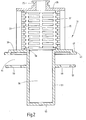
- the device has a designated as a whole with 1 filter housing, which consists of two parts of a housing upper part 3 in the form of a round bell and a lower closure member 5 which is screwed into the lower, open end of the upper part 3.
- the internally threaded end portion 7 of the upper part 3 engages over the connecting portion 9 of the lower part 5, so that in the screwed state, the end edge 11 of the closure member 5 is within the housing upper part 3 at a distance from the lower end.
- a sealing element 17 is arranged to the housing seal.
- the connection 15 is located at the top (viewing direction accordingly Fig.1 and 4 ) of the upper housing part 3 in a central position with respect to the vertical axis 21 of the device.
- the outlet connection 15 has an inner extension 23, which forms a kind of element receptacle in which a nozzle 25 with sealing element 27 can be accommodated.
- the nozzle 25 is located on an end plate 29 of a filter element, which in the Fig.2 and 3 shown separately and designated as a whole with 31. With the filter element 31 in the functional position, see Fig.1 and 3 , the outflow port 15 is via the port 25 in direct fluid communication with the inner filter cavity 33 of the filter element 31, which forms the clean side in the filtration.
- the filter element 31 which can be flowed through from the outside to the inner filter cavity 33 has a support structure for the hollow cylindrical filter medium 35 which forms a fluid-permeable support tube 37 which surrounds the inner filter cavity 33 and is surrounded on the outside by the filter medium 35.
- This support tube 37 extends from the upper end plate 29 to a disc 39, which, like the upper plate 29, forms a termination for the relevant end of the filter medium 35, but has a larger diameter than the end plate 29.
- the disc 29 has the form of an incomplete, ie interruption 41 (see Figure 3 ) having circular disk, 41 through these interruptions passages 43 ( Figure 4 ) are formed, which allow a medium flow through the disc 39.
- the disc 39 forms a step 47, which, when the filter element 31 is arranged in its functional position in the filter housing 1, abuts against an inner step 49 of the upper housing part 3 (s. Fig.1 ).
- the inner filter cavity 33 Via an opening 51 of the disc 39, the inner filter cavity 33, ie the clean side of the device in direct communication with a directly formed on the disc 39 cylindrical pot 53 with closed pot bottom 55.
- the pot 53 forms, as discussed later, a plenum , which designates here as the second collection space 36 is, for flowing out of the inner filter cavity 33 fluid, ie in the present case of oil droplets, which are deposited on the filter medium 35 by coalescence from the natural gas stream.
- a second disc 57 is integrally formed on the pot 53, which extends in a parallel plane to the first disc 39 and has a slightly smaller diameter than the latter.
- the second disk 57 like the first disk 39, has passages 59.
- the discs 39 and 57 act as dividing elements and define as upper wall or lower wall the inflow space 61 between them, in which the first stage of the deposition takes place.
- the Fig.1 and 4 show the filter element 31 in its installed functional position. When screwed into the upper housing part 3 closure part 5 this lies with its end edge 11 on the second disc 57 at. At the same time, the bottom 55 of the pot 53 is in abutment with the bottom part 13 of the closure part 5. As a result, the steps 47 and 49 on the upper disc 39 and the upper housing part 3 with each other in abutment and the nozzle 25 of the filter element 31 is in serving as an element receiving Extension 23 secured to the outlet connection 15. As the Fig. 1 and 4 show the housing inlet 19 opens with the designated inlet opening 63 so tangential to the inner wall 65 in the inflow space 61, that in this a swirl flow is generated.
- the phase separation takes place in the manner of a cyclone separator by centrifugal action.
- the thus separated fluid flows via the passages 59 of the lower disc 57 into the first collecting space 67, which surrounds the outside of the pot 53 in the closure part 5, which is held at its bottom 55 between centering bodies 69 protruding inwardly from the bottom region 13 of the closure part 5 ,
Abstract
Description
- Die Erfindung betrifft eine Vorrichtung zum Abscheiden von in gasförmigen Medien enthaltenen Fluiden, insbesondere von Öl aus Gaskraftstoffen für Verbrennungsmotoren, mit einem Gehäuse, das einen Einströmraum für das über einen Gehäuseeingang einströmende Medium aufweist, wobei der Einströmraum durch Trennelemente von einem Fluidsammelraum, in den im Einströmraum abgeschiedenes Fluid über Durchlässe des Trennelementes durch Schwerkraftwirkung einströmbar ist, und von einem Filterraum getrennt ist, in dem ein Abscheideeigenschaften aufweisendes Filterelement vom Medienstrom durchströmbar ist, der über Durchlässe des Trennelementes eintritt, und wobei sich an die Reinseite des Filterelementes ein Ausströmanschluss für das gereinigte Medium sowie ein zweiter Fluidsammelraum anschließen, in den am Filterelement abgeschiedenes Fluid durch Schwerkraftwirkung einfließt.
- Für den Betrieb von Kraftfahrzeugen werden anstelle von flüssigen Kraftstoffen (Benzin, Dieselöl) zunehmend Gaskraftstoffe benutzt, deren Einsatz sowohl ökonomische als auch ökologische, die Abgassituation betreffende Vorteile bietet. Um im Gastank von mit Erdgas betriebenen Kraftfahrzeugen eine größere Kraftstoffmenge zu speichern, ist es erforderlich, den Gaskraftstoff im Gastank unter einem hohen Druck von beispielsweise 200 bis 300 bar zu verdichten. Dabei besteht die Gefahr, dass der Gaskraftstoff mit Schmieröl des zur Betankung eingesetzten Verdichters verunreinigt wird. Hauptursache hierfür ist, dass bei Anstieg der Temperatur in den Hochdruckstufen der Verdichter Schmieröl verdampft und in gasförmiger Form oder als Aerosol in den Gaskraftstoff gelangt. Wenn dieser für den Betrieb des betreffenden Verbrennungsmotors wieder auf den hierfür geeigneten Gasdruck entspannt wird, dann kühlt sich der Gaskraftstoff ab, wodurch die mitgeführten Ölbestandteile kondensieren und in flüssiger Form oder als Aerosol im Gaskraftstoff enthalten sind. Für einen störungsfreien Betrieb des Verbrennungsmotors ist es daher erforderlich, in dem Zuleitungsystem zwischen dem Gastank und dem Verbrennungsmotor einen Ölabscheider vorzusehen, der üblicherweise auf der Niederdruckseite des Druckminderers vorgesehen ist, so das der Ölabscheider lediglich Druckfestigkeit gegen Niederdruck haben muß.
- Ein für einen derartigen Einsatzzweck vorgesehener Ölabscheider ist aus dem Dokument
EP 1 884 651 B1 bekannt. Diese Vorrichtung weist ein dreiteiliges Gehäuse auf, dessen Mittelteil den Einströmraum bildet, der durch eine obere Wand und eine untere Wand, die zueinander parallele Ebenen bilden, sowie durch eine sich entlang der Gehäusehochachse erstreckende Seitenwand begrenzt ist. Obere Wand und untere Wand bilden ein Trennelement gegenüber einem darüberliegenden Gehäuseteil, der einen Filterraum bildet, sowie einem darunterliegenden dritten Gehäuseteil, der Sammelräume für abgeschiedenes Öl beinhaltet. Obere Wand und untere Wand des Einströmraumes, die als Trennelement dienen, weisen jeweils Durchlässe zum Filterraum bzw. zu den Fluidsammelräumen auf. Beim Betrieb der bekannten Vorrichtung gelangen Ölbestandteile, die in den Einströmraum durch Schwerkraftabscheidung aus dem Gaskraftstoff abgeschieden sind, über die Durchlässe der unteren Wand in den ersten Fluidsammelraum, bevor der Gaskraftstoff durch die Durchlässe in der oberen Wand des Einströmraumes zum Filterraum gelangt. Nach Durchströmen des Filtermediums des Filterelementes durch Koaleszenz und Schwerkraft gelangt weiter abgeschiedenes Öl in den an der Reinseite des Filterelementes angeschlossenen zweiten Fluidsammelraum, der sich im unteren Gehäuseteil, gesondert von dem ersten Fluidsammelraum, befindet. - Der Erfindung liegt die Aufgabe zugrunde, eine Abscheidevorrichtung der besagten Art zur Verfügung zu stellen, die sich im Vergleich zum Stand der Technik durch verbesserte Betriebseigenschaften auszeichnet.
- Erfindungsgemäß ist diese Aufgabe durch eine Vorrichtung gelöst, die die Merkmale des Patentanspruches 1 in seiner Gesamtheit aufweist.
- Demgemäß besteht eine wesentliche Besonderheit der Erfindung darin, dass der in den Einströmraum führende Gehäuseeingang derart tangential zur Innenwand des Einströmraumes gerichtet ist, dass in diesem eine eine Fluidabscheidung durch Zentrifugalkräfte bewirkende Drallströmung erzeugt ist. Während beim Stand der Technik die Abscheidung in der die erste Abscheidestufe bildenden Einströmkammer durch Gravitation erfolgt, bildet der Einströmraum bei der Erfindung mittels der Erzeugung einer Drallströmung einen Zyklonabscheider, so dass in der ersten Stufe eine erheblich verbesserte Abscheidewirkung erreicht wird. In Verbindung mit der in der zweiten Stufe am Filterelement stattfindenden weiteren Abscheidung ist eine insgesamt verbesserte Aufbereitung des über den Ausströmanschluss abgegebenen Mediums erreichbar.
- Bei besonders vorteilhaften Ausführungsbeispielen bildet der zweite Fluidsammelraum mit dem Filterelement ein einstückiges Bauteil. Hieraus erwachsen mehrere weitere Vorteile. So wird bei jedem Wechsel des Filterelementes auch das Auffangvolumen des an der Reinseite befindlichen Sammelraumes zusammen mit dem Filterelement erneuert. Beim Stand der Technik muss bei einem Filterelementwechsel in einem zusätzlichen Arbeitsgang der an der Reinseite angeschlossene Sammelraum entleert werden, um für den Betrieb mit dem neuen Filterelement wieder ein entsprechendes Auffangvolumen zur Verfügung zu stellen. Ein eventuell nicht vollständig entleerter Sammelraum hat beim Stand der Technik ein zu geringes, anfängliches Auffangvolumen zur Folge, was möglicherweise nicht bis zum nächsten Wartungsintervall ausreicht, so dass Öl mit dem Gaskraftstoff zum Motor gelangen kann. Ein weiterer Vorteil ist die verbesserte Wartungsfreundlichkeit, weil der an das Filterelement angeformte zweite Sammelraum eine verlängerte Handhabe bildet, an der für den Filterwechsel das Filterelement bequem gegriffen und aus dem Filtergehäuse herausgezogen werden kann.
- Bei einem besonders bevorzugten Ausführungsbeispiel sind die Wände des Einströmraumes, die die Trennelemente zwischen Einströmraum und dem Filterraum sowie dem ersten Fluidsammelraum bilden, einstückige Bestandteile des Filterelementes. Dieses bildet somit nicht nur den zweiten Sammelraum als integralen Bestandteil, sondern mit oberer und unterer Trennwand auch die axiale Begrenzung des Einströmraumes aus, so dass das beim Stand der Technik erforderliche, gesonderte Gehäusemittelteil entfällt.
- In besonders vorteilhafter Weise ist das bei der Filtration von seiner Außenseite zu seinem inneren Filterhohlraum hin durchströmbare Filterelement auf einer die obere Wand des Einströmraumes bildenden Scheibe angeordnet, die am unteren Ende des Filterhohlraumes eine Öffnung besitzt, an die sich der zweite Fluidsammelraum in Form eines sich entlang der Hochachse des Filterelementes erstreckenden, mit der Scheibe einstückigen Topfes anschließt.
- Mit besonderem Vorteil kann hier die Anordnung so getroffen sein, dass die untere Wand des Einströmraumes durch eine zweite, sich einstückig an die Außenseite des Topfes anschließende Scheibe gebildet ist. In diesen als die Trennelemente fungierenden Scheiben befinden sich die jeweiligen Durchlässe, die vom Einströmraum zum Filterraum und vom Einströmraum zum ersten Fluidsammelraum führen.
- Bei besonders vorteilhaften Ausführungsbeispielen weist das Gehäuse ein glockenartiges Oberteil mit dem Ausströmanschluss, mit dem das obere Ende des Filterhohlraumes des in Funktionsposition befindlichen Filterelementes in abgedichtete Fluidverbindung kommt, sowie an seiner Innenseite eine Stufe für die Anlage des Umfangsrandes der ersten oberen Scheibe auf.
- Dabei kann die Anordnung so getroffen sein, dass das Gehäuse ein Verschlussteil aufweist, das unter Bildung einer Abdichtung in das untere, offene Ende des glockenartigen Oberteils derart einschraubbar ist, dass es mit seinem Endrand an der unteren, zweiten Scheibe anliegt.
- In besonders vorteilhafter Weise kann das Verschlussteil an seinem Bodenteil nach innen vorstehende Zentrierkörper aufweisen, zwischen denen der Bodenbereich des den zweiten Fluidsammelraum bildenden Topfes zentriert aufnehmbar ist, wobei der übrige, den Topf umgebende Innenraum des Verschlussteils den ersten Fluidsammelraum bildet. Bei vom Gehäuseoberteil abgenommenem Verschlussteil ist dessen Innenraum und damit der erste Fluidsammelraum besonders bequem für Reinigungsarbeiten zugänglich, weil sich kein zweiter Sammelraum, da er am Filterelement verbleibt, in den zu reinigenden Bereich erstreckt, in dem sich lediglich die kleinen, nicht hindernden Zentrierkörper befinden.
- Nachstehend ist die Erfindung anhand eines in der Zeichnung dargestellten Ausführungsbeispiels im Einzelnen erläutert.
- Es zeigen:
- Fig.1
- einen Längsschnitt des Ausführungsbeispiels der erfindungsgemäßen Vorrichtung;
- Fig.2
- in gegenüber
Fig.1 geringfügig vergrößerter Darstellung einen Längsschnitt lediglich des Filterelements des Ausführungsbeispiels; - Fig.3
- eine perspektivische Schrägansicht des längs aufgeschnittenen Filterelements und
- Fig.4
- eine perspektivische Schrägansicht des im Winkel von 90° längs geschnittenen Ausführungsbeispiels der Vorrichtung.
- Nachstehend ist die Erfindung am Beispiel einer Erdgas-Filtervorrichtung für die Kraftstoffversorgung eines Verbrennungsmotors erläutert. Die Vorrichtung weist ein als Ganzes mit 1 bezeichnetes Filtergehäuse auf, das zweiteilig aus einem Gehäuseoberteil 3 in Form einer runden Glocke und einem unteren Verschlussteil 5 besteht, das in das untere, offene Ende des Oberteils 3 einschraubbar ist. Dabei übergreift der mit Innengewinde versehene Endabschnitt 7 des Oberteils 3 den Verbindungsabschnitt 9 des Unterteils 5, so dass im eingeschraubten Zustand sich der Endrand 11 des Verschlussteils 5 innerhalb des Gehäuseoberteils 3 in einem Abstand von dessen unterem Ende befindet. In der Nähe dieses Endes ist ein Dichtelement 17 zur Gehäuseabdichtung angeordnet.
- Während das Verschlussteil 5 an seinem Bodenbereich 13 geschlossen ist, weist das Gehäuseoberteil 3 einen Ausströmanschluss 15 sowie einen Gehäuseeingang 19 auf. Der Anschluss 15 befindet sich an der Oberseite (Blickrichtung entsprechend
Fig.1 und4 ) des Gehäuseoberteils 3 in zentraler Lage bezüglich der Hochachse 21 der Vorrichtung. Der Ausströmanschluss 15 weist eine innere Erweiterung 23 auf, die eine Art Elementaufnahme bildet, in der ein Stutzen 25 mit Dichtelement 27 aufnehmbar ist. Der Stutzen 25 befindet sich an einer Endplatte 29 eines Filterelementes, das in denFig.2 und3 gesondert dargestellt und als Ganzes mit 31 bezeichnet ist. Bei in Funktionsposition befindlichem Filterelement 31, sieheFig.1 und3 , ist der Ausströmanschluss 15 über den Stutzen 25 in unmittelbarer Fluidverbindung mit dem inneren Filterhohlraum 33 des Filterelements 31, der bei der Filtration die Reinseite bildet. - Nähere Einzelheiten des Filterelements 31 sind insbesondere aus
Fig.2 und3 deutlicher ersichtlich. Das bei der Filtration von außen zum inneren Filterhohlraum 33 hin durchströmbare Filterelement 31 weist für das hohlzylinderförmige Filtermedium 35 eine Stützstruktur auf, die ein fluiddurchlässiges Stützrohr 37 bildet, das den inneren Filterhohlraum 33 umgibt und außenseitig vom Filtermedium 35 umgeben ist. Dieses Stützrohr 37 erstreckt sich von der oberen Endplatte 29 bis zu einer Scheibe 39, die, ähnlich wie die obere Platte 29, einen Abschluss für das betreffende Ende des Filtermediums 35 bildet, jedoch einen größeren Durchmesser als die Endplatte 29 besitzt. Genauer gesagt, hat die Scheibe 29 die Form einer unvollständigen, d.h. Unterbrechungen 41 (sieheFig.3 ) aufweisenden Kreisscheibe, wobei durch diese Unterbrechungen 41 Durchlässe 43 (Fig.4 ) gebildet sind, die einen Mediendurchstrom durch die Scheibe 39 ermöglichen. An ihrem Umfangsrand 45 bildet die Scheibe 39 eine Stufe 47, die, wenn das Filterelement 31 in seiner Funktionsposition im Filtergehäuse 1 angeordnet ist, an einer inneren Stufe 49 des Gehäuseoberteils 3 anliegt (s.Fig.1 ). - Über eine Öffnung 51 der Scheibe 39 ist der innere Filterhohlraum 33, d.h. die Reinseite der Vorrichtung, in unmittelbarer Verbindung mit einem an die Scheibe 39 unmittelbar angeformten zylindrischen Topf 53 mit geschlossenem Topfboden 55. Der Topf 53 bildet, wie später noch besprochen, einen Sammelraum, der hier als zweiter Sammelraum 36 bezeichnet ist, für aus dem inneren Filterhohlraum 33 abfließendes Fluid, d.h. im vorliegenden Falle von Öltröpfchen, die am Filtermedium 35 durch Koaleszenz aus dem Erdgasstrom abgeschieden sind. In einem axialen Abstand von der Scheibe 39 ist am Topf 53 eine zweite Scheibe 57 einstückig angeformt, die sich in paralleler Ebene zur ersten Scheibe 39 erstreckt und einen geringfügig kleineren Durchmesser als letztere besitzt. Die zweite Scheibe 57 weist wie die erste Scheibe 39 Durchlässe 59 auf. Die Scheiben 39 und 57 fungieren als Trennelemente und begrenzen als obere Wand bzw. untere Wand den zwischen ihnen befindlichen Einströmraum 61, in dem die erste Stufe des Abscheidevorganges stattfindet.
- Die
Fig.1 und4 zeigen das Filterelement 31 in seiner eingebauten Funktionsposition. Bei in das Gehäuseoberteil 3 eingeschraubtem Verschlussteil 5 liegt dieses mit seinem Endrand 11 an der zweiten Scheibe 57 an. Gleichzeitig ist der Boden 55 des Topfes 53 in Anlage am Bodenteil 13 des Verschlussteils 5. Dadurch sind die Stufen 47 und 49 an der oberen Scheibe 39 bzw. dem Gehäuseoberteil 3 miteinander in Anlage und der Stutzen 25 des Filterelements 31 ist in der als Elementaufnahme dienenden Erweiterung 23 am Ausströmanschluss 15 gesichert. Wie dieFig. 1 und4 zeigen, mündet der Gehäuseeingang 19 mit der mit 63 bezeichneten Einströmöffnung derart tangential zur Innenwand 65 in den Einströmraum 61, dass in diesem eine Drallströmung erzeugt wird. In der im Einströmraum 61 erfolgenden ersten Abscheidestufe erfolgt daher die Phasentrennung nach Art eines Zyklonabscheiders durch Zentrifugalwirkung. Das so abgeschiedene Fluid fließt über die Durchlässe 59 der unteren Scheibe 57 in den ersten Sammelraum 67 ab, der im Verschlussteil 5 die Außenseite des Topfes 53 umgibt, der an seinem Boden 55 zwischen vom Bodenbereich 13 des Verschlussteils 5 nach innen vorstehenden Zentrierkörpern 69 gehalten ist.
Claims (8)
- Vorrichtung zum Abscheiden von in gasförmigen Medien enthaltenen Fluiden, insbesondere von Öl aus Gaskraftstoffen für Verbrennungsmotoren, mit einem Gehäuse (1), das einen Einströmraum (61) für das über einen Gehäuseeingang (19) einströmende Medium aufweist, wobei der Einströmraum (61) durch Trennelemente (39,57) von einem Fluidsammelraum (67), in den im Einströmraum (61) abgeschiedenes Fluid über Durchlässe (59) des Trennelementes (57) durch Schwerkraftwirkung einströmbar ist, und von einem Filterraum getrennt ist, in dem ein Abscheideeigenschaften aufweisendes Filterelement (31) vom Medienstrom durchströmbar ist, der über Durchlässe (43) des Trennelementes (39) eintritt, und wobei sich an die Reinseite (33) des Filterelementes (31) ein Ausströmanschluss (15) für das gereinigte Medium sowie ein zweiter Fluidsammelraum (36,53) anschließen, in den am Filterelement (31) abgeschiedenes Fluid durch Schwerkraftwirkung einfließt, dadurch gekennzeichnet, dass der in den Einströmraum (61) führende Gehäuseeingang (19,63) derart tangential zur Innenwand (65) des Einströmraumes (61) gerichtet ist, dass in diesem eine eine Fluidabscheidung durch Zentrifugalkräfte bewirkende Drallströmung erzeugt ist.
- Vorrichtung nach Anspruch 1, dadurch gekennzeichnet, dass der zweite Fluidsammelraum (36,53) mit dem Filterelement (31) ein einstückiges Bauteil bildet.
- Vorrichtung nach Anspruch 1 oder 2, dadurch gekennzeichnet, dass die Wände des Einströmraumes (61), die die Trennelemente (39,57) zwischen Einströmraum (61) und dem Filterraum sowie dem ersten Fluidsammelraum (67) bilden, einstückige Bestandteile des Filterelementes (31) sind.
- Vorrichtung nach einem der vorstehenden Ansprüche, dadurch gekennzeichnet, dass das bei der Filtration von seiner Außenseite zu seinem inneren Filterhohlraum (33) hin durchströmbare Filterelement (31) auf einer die obere Wand des Einströmraumes (61) bildenden Scheibe (39) angeordnet ist, die am unteren Ende des Filterhohlraumes (33) eine Öffnung (51) besitzt, an die sich der zweite Fluidsammelraum (36) in Form eines sich entlang der Hochachse (21) des Filterelementes (31) erstreckenden, mit der Scheibe (39) einstückigen Topfes (53) anschließt.
- Vorrichtung nach einem der vorstehenden Ansprüche, dadurch gekennzeichnet, dass die untere Wand des Einströmraumes (61) durch eine zweite, sich einstückig an die Außenseite des Topfes (53) anschließende Scheibe (57) gebildet ist.
- Vorrichtung nach einem der vorstehenden Ansprüche, dadurch gekennzeichnet, dass das Gehäuse (1) ein glockenartiges Oberteil (3) mit dem Ausströmanschluss (15), mit dem das obere Ende des Filterhohlraumes (33) des in Funktionsposition befindlichen Filterelementes (31) in abgedichtete Fluidverbindung kommt, sowie an seiner Innenseite eine Stufe (49) für die Anlage des Umfangsrandes (45,47) der ersten, oberen Scheibe (39) aufweist.
- Vorrichtung nach einem der vorstehenden Ansprüche, dadurch gekennzeichnet, dass das Gehäuse (1) ein Verschlussteil (5) aufweist, das unter Bildung einer Abdichtung (17) in das untere, offene Ende des glockenartigen Oberteils (3) derart einschraubbar ist, dass es mit seinem Endrand (11) an der unteren, zweiten Scheibe (57) anliegt.
- Vorrichtung nach einem der vorstehenden Ansprüche, dadurch gekennzeichnet, dass das Verschlussteil (5) an seinem Bodenteil (13) nach innen vorstehende Zentrierkörper (69) aufweist, zwischen denen der Bodenbereich (55) des den zweiten Fluidsammelraum (36) bildenden Topfes (53) zentriert aufnehmbar ist, und dass der übrige, den Topf (53) umgebende Innenraum des Verschlussteils (5) den ersten Fluidsammelraum (67) bildet.
Applications Claiming Priority (1)
| Application Number | Priority Date | Filing Date | Title |
|---|---|---|---|
| DE102011009232A DE102011009232A1 (de) | 2011-01-22 | 2011-01-22 | Vorrichtung zum Abscheiden von in gasförmigen Medien enthaltenen Fluiden, insbesondere Öl aus Gaskraftstoffen für Verbrennungsmotoren |
Publications (3)
| Publication Number | Publication Date |
|---|---|
| EP2478949A2 true EP2478949A2 (de) | 2012-07-25 |
| EP2478949A3 EP2478949A3 (de) | 2016-10-19 |
| EP2478949B1 EP2478949B1 (de) | 2018-01-03 |
Family
ID=45558479
Family Applications (1)
| Application Number | Title | Priority Date | Filing Date |
|---|---|---|---|
| EP12000230.8A Active EP2478949B1 (de) | 2011-01-22 | 2012-01-17 | Vorrichtung zum Abscheiden von in gasförmigen Medien enthaltenen Fluiden, insbesondere öl aus Gaskraftstoffen für Verbrennungsmotoren |
Country Status (2)
| Country | Link |
|---|---|
| EP (1) | EP2478949B1 (de) |
| DE (1) | DE102011009232A1 (de) |
Cited By (1)
| Publication number | Priority date | Publication date | Assignee | Title |
|---|---|---|---|---|
| EP3027879A4 (de) * | 2013-08-02 | 2017-11-08 | Alternative Fuel Containers, LLC | Vorfiltereinheit für fahrzeugbrenngas |
Families Citing this family (1)
| Publication number | Priority date | Publication date | Assignee | Title |
|---|---|---|---|---|
| DE102012017101A1 (de) * | 2012-08-29 | 2014-05-15 | Hydac Process Technology Gmbh | Trennvorrichtung zum Abtrennen von Verschmutzungen aus Gasen |
Citations (1)
| Publication number | Priority date | Publication date | Assignee | Title |
|---|---|---|---|---|
| EP1884651B1 (de) | 2006-08-01 | 2009-09-30 | GM Global Technology Operations, Inc. | Ölabscheider für gasbetriebene Brennkraftmaschinen |
Family Cites Families (2)
| Publication number | Priority date | Publication date | Assignee | Title |
|---|---|---|---|---|
| JP2006083809A (ja) * | 2004-09-17 | 2006-03-30 | Yamaha Motor Co Ltd | エンジン駆動式乗り物用オイルタンク |
| CN201351587Y (zh) * | 2009-02-11 | 2009-11-25 | 绍兴瑞气压缩机有限公司 | 空压机用油气分离筒 |
-
2011
- 2011-01-22 DE DE102011009232A patent/DE102011009232A1/de not_active Withdrawn
-
2012
- 2012-01-17 EP EP12000230.8A patent/EP2478949B1/de active Active
Patent Citations (1)
| Publication number | Priority date | Publication date | Assignee | Title |
|---|---|---|---|---|
| EP1884651B1 (de) | 2006-08-01 | 2009-09-30 | GM Global Technology Operations, Inc. | Ölabscheider für gasbetriebene Brennkraftmaschinen |
Cited By (2)
| Publication number | Priority date | Publication date | Assignee | Title |
|---|---|---|---|---|
| EP3027879A4 (de) * | 2013-08-02 | 2017-11-08 | Alternative Fuel Containers, LLC | Vorfiltereinheit für fahrzeugbrenngas |
| US9933116B2 (en) | 2013-08-02 | 2018-04-03 | Alternative Fuel Containers, Llc | Vehicle fuel gas pre-filter unit |
Also Published As
| Publication number | Publication date |
|---|---|
| DE102011009232A1 (de) | 2012-07-26 |
| EP2478949B1 (de) | 2018-01-03 |
| EP2478949A3 (de) | 2016-10-19 |
Similar Documents
| Publication | Publication Date | Title |
|---|---|---|
| EP2308581B1 (de) | Luftentölelement für einen Luftverdichter und Luftverdichtungsanlage | |
| EP3341109B1 (de) | Abscheidevorrichtung | |
| EP2145099B1 (de) | Kraftstoffzuführeinrichtung, insbesondere für eine brennkraftmaschine | |
| EP2663378B1 (de) | Filtervorrichtung | |
| EP3641909B1 (de) | Filtersystem mit filterelement und sekundärelement zum verschliesen eines mittelrohrs | |
| DE102013012918B4 (de) | Flüssigkeitsfilter und Filterelement, insbesondere für Kraftstoff | |
| EP3180131B1 (de) | Vorrichtung zur behandlung von fluidgemischen | |
| DE202014011016U1 (de) | Becherförmiges Gehäuse und Vorrichtung zum Abscheiden von Flüssigkeit aus Luft | |
| DE102015003165A1 (de) | Kraftstofffilter mit einem Kraftstofffiltereinsatz mit einem Vor- und einem Hauptfilterelement | |
| WO2014082762A1 (de) | Filter, filterelement, filtergehäuse und ablassvorrichtung eines filters | |
| DE102011119868A1 (de) | Filtervorrichtung | |
| CH675278A5 (de) | ||
| DE102015003162A1 (de) | Kraftstofffiltereinsatz mit einem Vor- und einem Hauptfilterelement sowie Kraftstofffilter | |
| EP1399240A2 (de) | Filterelement mit drainagerohr | |
| EP2478949B1 (de) | Vorrichtung zum Abscheiden von in gasförmigen Medien enthaltenen Fluiden, insbesondere öl aus Gaskraftstoffen für Verbrennungsmotoren | |
| EP2255883A1 (de) | Zyklonabscheidevorrichtung | |
| WO2016146424A1 (de) | Kraftstofffiltereinsatz und kraftstofffilter mit einem vor- und einem hauptfilterelement sowie mit einer wasserabscheideeinheit | |
| DE202007003292U1 (de) | Ölabscheider mit mindestens einem Zyklon | |
| DE102014007302A1 (de) | Filtervorrichtung | |
| DE102016009487A1 (de) | Abscheideelement, Vorrichtung sowie Verfahren zur Abscheidung von Flüssigkeit aus Rohgas oder aus Rohgasgemisch einer Kraftmaschine/Kompressors | |
| DE102018110317A1 (de) | Filtersystem mit einem Filterelement | |
| DE102017001100A1 (de) | Fluidfilter mit einem Filtereinsatz mit einem Vor- und einem Hauptfilterelement | |
| WO2016146426A1 (de) | Kraftstofffiltereinsatz mit einem vor- und einem hauptfilterelement sowie kraftstofffilter | |
| EP3357555A1 (de) | Flüssigkeitsfiltereinsatz und flüssigkeitsfilter mit korrosionsschutz für äussere pumpen | |
| DE102022102039A1 (de) | Filtervorrichtung zum Filtern eines Fluids, Verwendung eines Filterelements in einer Filtervorrichtung, und Verfahren zum Austausch eines Filterelements |
Legal Events
| Date | Code | Title | Description |
|---|---|---|---|
| PUAI | Public reference made under article 153(3) epc to a published international application that has entered the european phase |
Free format text: ORIGINAL CODE: 0009012 |
|
| AK | Designated contracting states |
Kind code of ref document: A2 Designated state(s): AL AT BE BG CH CY CZ DE DK EE ES FI FR GB GR HR HU IE IS IT LI LT LU LV MC MK MT NL NO PL PT RO RS SE SI SK SM TR |
|
| AX | Request for extension of the european patent |
Extension state: BA ME |
|
| PUAL | Search report despatched |
Free format text: ORIGINAL CODE: 0009013 |
|
| AK | Designated contracting states |
Kind code of ref document: A3 Designated state(s): AL AT BE BG CH CY CZ DE DK EE ES FI FR GB GR HR HU IE IS IT LI LT LU LV MC MK MT NL NO PL PT RO RS SE SI SK SM TR |
|
| AX | Request for extension of the european patent |
Extension state: BA ME |
|
| RIC1 | Information provided on ipc code assigned before grant |
Ipc: B01D 45/16 20060101ALI20160909BHEP Ipc: B01D 45/02 20060101AFI20160909BHEP Ipc: F02M 21/02 20060101ALI20160909BHEP Ipc: B01D 46/00 20060101ALI20160909BHEP |
|
| 17P | Request for examination filed |
Effective date: 20161025 |
|
| GRAP | Despatch of communication of intention to grant a patent |
Free format text: ORIGINAL CODE: EPIDOSNIGR1 |
|
| INTG | Intention to grant announced |
Effective date: 20170908 |
|
| GRAS | Grant fee paid |
Free format text: ORIGINAL CODE: EPIDOSNIGR3 |
|
| GRAA | (expected) grant |
Free format text: ORIGINAL CODE: 0009210 |
|
| REG | Reference to a national code |
Ref country code: FR Ref legal event code: PLFP Year of fee payment: 7 |
|
| AK | Designated contracting states |
Kind code of ref document: B1 Designated state(s): AL AT BE BG CH CY CZ DE DK EE ES FI FR GB GR HR HU IE IS IT LI LT LU LV MC MK MT NL NO PL PT RO RS SE SI SK SM TR |
|
| REG | Reference to a national code |
Ref country code: GB Ref legal event code: FG4D Free format text: NOT ENGLISH |
|
| REG | Reference to a national code |
Ref country code: CH Ref legal event code: EP Ref country code: AT Ref legal event code: REF Ref document number: 959706 Country of ref document: AT Kind code of ref document: T Effective date: 20180115 |
|
| REG | Reference to a national code |
Ref country code: IE Ref legal event code: FG4D Free format text: LANGUAGE OF EP DOCUMENT: GERMAN |
|
| REG | Reference to a national code |
Ref country code: DE Ref legal event code: R096 Ref document number: 502012011921 Country of ref document: DE |
|
| REG | Reference to a national code |
Ref country code: NL Ref legal event code: MP Effective date: 20180103 |
|
| REG | Reference to a national code |
Ref country code: LT Ref legal event code: MG4D |
|
| PG25 | Lapsed in a contracting state [announced via postgrant information from national office to epo] |
Ref country code: NL Free format text: LAPSE BECAUSE OF FAILURE TO SUBMIT A TRANSLATION OF THE DESCRIPTION OR TO PAY THE FEE WITHIN THE PRESCRIBED TIME-LIMIT Effective date: 20180103 |
|
| PG25 | Lapsed in a contracting state [announced via postgrant information from national office to epo] |
Ref country code: HR Free format text: LAPSE BECAUSE OF FAILURE TO SUBMIT A TRANSLATION OF THE DESCRIPTION OR TO PAY THE FEE WITHIN THE PRESCRIBED TIME-LIMIT Effective date: 20180103 Ref country code: ES Free format text: LAPSE BECAUSE OF FAILURE TO SUBMIT A TRANSLATION OF THE DESCRIPTION OR TO PAY THE FEE WITHIN THE PRESCRIBED TIME-LIMIT Effective date: 20180103 Ref country code: LT Free format text: LAPSE BECAUSE OF FAILURE TO SUBMIT A TRANSLATION OF THE DESCRIPTION OR TO PAY THE FEE WITHIN THE PRESCRIBED TIME-LIMIT Effective date: 20180103 Ref country code: CY Free format text: LAPSE BECAUSE OF FAILURE TO SUBMIT A TRANSLATION OF THE DESCRIPTION OR TO PAY THE FEE WITHIN THE PRESCRIBED TIME-LIMIT Effective date: 20180103 Ref country code: NO Free format text: LAPSE BECAUSE OF FAILURE TO SUBMIT A TRANSLATION OF THE DESCRIPTION OR TO PAY THE FEE WITHIN THE PRESCRIBED TIME-LIMIT Effective date: 20180403 Ref country code: FI Free format text: LAPSE BECAUSE OF FAILURE TO SUBMIT A TRANSLATION OF THE DESCRIPTION OR TO PAY THE FEE WITHIN THE PRESCRIBED TIME-LIMIT Effective date: 20180103 |
|
| PG25 | Lapsed in a contracting state [announced via postgrant information from national office to epo] |
Ref country code: IS Free format text: LAPSE BECAUSE OF FAILURE TO SUBMIT A TRANSLATION OF THE DESCRIPTION OR TO PAY THE FEE WITHIN THE PRESCRIBED TIME-LIMIT Effective date: 20180503 Ref country code: GR Free format text: LAPSE BECAUSE OF FAILURE TO SUBMIT A TRANSLATION OF THE DESCRIPTION OR TO PAY THE FEE WITHIN THE PRESCRIBED TIME-LIMIT Effective date: 20180404 Ref country code: PL Free format text: LAPSE BECAUSE OF FAILURE TO SUBMIT A TRANSLATION OF THE DESCRIPTION OR TO PAY THE FEE WITHIN THE PRESCRIBED TIME-LIMIT Effective date: 20180103 Ref country code: RS Free format text: LAPSE BECAUSE OF FAILURE TO SUBMIT A TRANSLATION OF THE DESCRIPTION OR TO PAY THE FEE WITHIN THE PRESCRIBED TIME-LIMIT Effective date: 20180103 Ref country code: SE Free format text: LAPSE BECAUSE OF FAILURE TO SUBMIT A TRANSLATION OF THE DESCRIPTION OR TO PAY THE FEE WITHIN THE PRESCRIBED TIME-LIMIT Effective date: 20180103 Ref country code: LV Free format text: LAPSE BECAUSE OF FAILURE TO SUBMIT A TRANSLATION OF THE DESCRIPTION OR TO PAY THE FEE WITHIN THE PRESCRIBED TIME-LIMIT Effective date: 20180103 Ref country code: BG Free format text: LAPSE BECAUSE OF FAILURE TO SUBMIT A TRANSLATION OF THE DESCRIPTION OR TO PAY THE FEE WITHIN THE PRESCRIBED TIME-LIMIT Effective date: 20180403 |
|
| REG | Reference to a national code |
Ref country code: CH Ref legal event code: PL |
|
| PG25 | Lapsed in a contracting state [announced via postgrant information from national office to epo] |
Ref country code: MT Free format text: LAPSE BECAUSE OF FAILURE TO SUBMIT A TRANSLATION OF THE DESCRIPTION OR TO PAY THE FEE WITHIN THE PRESCRIBED TIME-LIMIT Effective date: 20180103 |
|
| REG | Reference to a national code |
Ref country code: DE Ref legal event code: R097 Ref document number: 502012011921 Country of ref document: DE |
|
| PG25 | Lapsed in a contracting state [announced via postgrant information from national office to epo] |
Ref country code: LU Free format text: LAPSE BECAUSE OF NON-PAYMENT OF DUE FEES Effective date: 20180117 Ref country code: IT Free format text: LAPSE BECAUSE OF FAILURE TO SUBMIT A TRANSLATION OF THE DESCRIPTION OR TO PAY THE FEE WITHIN THE PRESCRIBED TIME-LIMIT Effective date: 20180103 Ref country code: AL Free format text: LAPSE BECAUSE OF FAILURE TO SUBMIT A TRANSLATION OF THE DESCRIPTION OR TO PAY THE FEE WITHIN THE PRESCRIBED TIME-LIMIT Effective date: 20180103 Ref country code: MC Free format text: LAPSE BECAUSE OF FAILURE TO SUBMIT A TRANSLATION OF THE DESCRIPTION OR TO PAY THE FEE WITHIN THE PRESCRIBED TIME-LIMIT Effective date: 20180103 Ref country code: EE Free format text: LAPSE BECAUSE OF FAILURE TO SUBMIT A TRANSLATION OF THE DESCRIPTION OR TO PAY THE FEE WITHIN THE PRESCRIBED TIME-LIMIT Effective date: 20180103 Ref country code: RO Free format text: LAPSE BECAUSE OF FAILURE TO SUBMIT A TRANSLATION OF THE DESCRIPTION OR TO PAY THE FEE WITHIN THE PRESCRIBED TIME-LIMIT Effective date: 20180103 |
|
| REG | Reference to a national code |
Ref country code: IE Ref legal event code: MM4A |
|
| REG | Reference to a national code |
Ref country code: BE Ref legal event code: MM Effective date: 20180131 |
|
| PLBE | No opposition filed within time limit |
Free format text: ORIGINAL CODE: 0009261 |
|
| STAA | Information on the status of an ep patent application or granted ep patent |
Free format text: STATUS: NO OPPOSITION FILED WITHIN TIME LIMIT |
|
| PG25 | Lapsed in a contracting state [announced via postgrant information from national office to epo] |
Ref country code: DK Free format text: LAPSE BECAUSE OF FAILURE TO SUBMIT A TRANSLATION OF THE DESCRIPTION OR TO PAY THE FEE WITHIN THE PRESCRIBED TIME-LIMIT Effective date: 20180103 Ref country code: LI Free format text: LAPSE BECAUSE OF NON-PAYMENT OF DUE FEES Effective date: 20180131 Ref country code: CZ Free format text: LAPSE BECAUSE OF FAILURE TO SUBMIT A TRANSLATION OF THE DESCRIPTION OR TO PAY THE FEE WITHIN THE PRESCRIBED TIME-LIMIT Effective date: 20180103 Ref country code: SK Free format text: LAPSE BECAUSE OF FAILURE TO SUBMIT A TRANSLATION OF THE DESCRIPTION OR TO PAY THE FEE WITHIN THE PRESCRIBED TIME-LIMIT Effective date: 20180103 Ref country code: CH Free format text: LAPSE BECAUSE OF NON-PAYMENT OF DUE FEES Effective date: 20180131 Ref country code: SM Free format text: LAPSE BECAUSE OF FAILURE TO SUBMIT A TRANSLATION OF THE DESCRIPTION OR TO PAY THE FEE WITHIN THE PRESCRIBED TIME-LIMIT Effective date: 20180103 Ref country code: BE Free format text: LAPSE BECAUSE OF NON-PAYMENT OF DUE FEES Effective date: 20180131 |
|
| 26N | No opposition filed |
Effective date: 20181005 |
|
| PG25 | Lapsed in a contracting state [announced via postgrant information from national office to epo] |
Ref country code: IE Free format text: LAPSE BECAUSE OF NON-PAYMENT OF DUE FEES Effective date: 20180117 |
|
| PG25 | Lapsed in a contracting state [announced via postgrant information from national office to epo] |
Ref country code: SI Free format text: LAPSE BECAUSE OF FAILURE TO SUBMIT A TRANSLATION OF THE DESCRIPTION OR TO PAY THE FEE WITHIN THE PRESCRIBED TIME-LIMIT Effective date: 20180103 |
|
| REG | Reference to a national code |
Ref country code: AT Ref legal event code: MM01 Ref document number: 959706 Country of ref document: AT Kind code of ref document: T Effective date: 20180117 |
|
| PG25 | Lapsed in a contracting state [announced via postgrant information from national office to epo] |
Ref country code: AT Free format text: LAPSE BECAUSE OF NON-PAYMENT OF DUE FEES Effective date: 20180117 |
|
| PG25 | Lapsed in a contracting state [announced via postgrant information from national office to epo] |
Ref country code: TR Free format text: LAPSE BECAUSE OF FAILURE TO SUBMIT A TRANSLATION OF THE DESCRIPTION OR TO PAY THE FEE WITHIN THE PRESCRIBED TIME-LIMIT Effective date: 20180103 |
|
| PG25 | Lapsed in a contracting state [announced via postgrant information from national office to epo] |
Ref country code: PT Free format text: LAPSE BECAUSE OF FAILURE TO SUBMIT A TRANSLATION OF THE DESCRIPTION OR TO PAY THE FEE WITHIN THE PRESCRIBED TIME-LIMIT Effective date: 20180103 Ref country code: HU Free format text: LAPSE BECAUSE OF FAILURE TO SUBMIT A TRANSLATION OF THE DESCRIPTION OR TO PAY THE FEE WITHIN THE PRESCRIBED TIME-LIMIT; INVALID AB INITIO Effective date: 20120117 |
|
| PG25 | Lapsed in a contracting state [announced via postgrant information from national office to epo] |
Ref country code: MK Free format text: LAPSE BECAUSE OF NON-PAYMENT OF DUE FEES Effective date: 20180103 |
|
| PGFP | Annual fee paid to national office [announced via postgrant information from national office to epo] |
Ref country code: DE Payment date: 20230131 Year of fee payment: 12 |
|
| PGFP | Annual fee paid to national office [announced via postgrant information from national office to epo] |
Ref country code: GB Payment date: 20231101 Year of fee payment: 13 |
|
| PGFP | Annual fee paid to national office [announced via postgrant information from national office to epo] |
Ref country code: FR Payment date: 20231127 Year of fee payment: 13 |