EP2478949A2 - Dispositif de séparation de fluides comprenant des milieux gazeux, notamment de l'huile à partir de carburants gazeux pour des moteurs à combustion interne - Google Patents
Dispositif de séparation de fluides comprenant des milieux gazeux, notamment de l'huile à partir de carburants gazeux pour des moteurs à combustion interne Download PDFInfo
- Publication number
- EP2478949A2 EP2478949A2 EP12000230A EP12000230A EP2478949A2 EP 2478949 A2 EP2478949 A2 EP 2478949A2 EP 12000230 A EP12000230 A EP 12000230A EP 12000230 A EP12000230 A EP 12000230A EP 2478949 A2 EP2478949 A2 EP 2478949A2
- Authority
- EP
- European Patent Office
- Prior art keywords
- fluid
- filter element
- space
- filter
- housing
- Prior art date
- Legal status (The legal status is an assumption and is not a legal conclusion. Google has not performed a legal analysis and makes no representation as to the accuracy of the status listed.)
- Granted
Links
- 239000012530 fluid Substances 0.000 title claims abstract description 39
- 239000000446 fuel Substances 0.000 title claims description 15
- 238000002485 combustion reaction Methods 0.000 title claims description 7
- 238000000926 separation method Methods 0.000 claims abstract description 10
- 230000005484 gravity Effects 0.000 claims description 6
- 238000001914 filtration Methods 0.000 claims description 4
- 230000002093 peripheral effect Effects 0.000 claims description 3
- 230000000694 effects Effects 0.000 abstract description 2
- 239000007789 gas Substances 0.000 description 10
- 239000003921 oil Substances 0.000 description 10
- VNWKTOKETHGBQD-UHFFFAOYSA-N methane Chemical compound C VNWKTOKETHGBQD-UHFFFAOYSA-N 0.000 description 6
- 239000003345 natural gas Substances 0.000 description 3
- 239000000443 aerosol Substances 0.000 description 2
- 238000004581 coalescence Methods 0.000 description 2
- 230000008021 deposition Effects 0.000 description 2
- 239000007788 liquid Substances 0.000 description 2
- 239000010687 lubricating oil Substances 0.000 description 2
- 238000012423 maintenance Methods 0.000 description 2
- 238000007789 sealing Methods 0.000 description 2
- 240000006829 Ficus sundaica Species 0.000 description 1
- 239000003638 chemical reducing agent Substances 0.000 description 1
- 238000004140 cleaning Methods 0.000 description 1
- 230000001747 exhibiting effect Effects 0.000 description 1
- 238000009434 installation Methods 0.000 description 1
- 238000005192 partition Methods 0.000 description 1
- 238000005191 phase separation Methods 0.000 description 1
Images


Classifications
-
- B—PERFORMING OPERATIONS; TRANSPORTING
- B01—PHYSICAL OR CHEMICAL PROCESSES OR APPARATUS IN GENERAL
- B01D—SEPARATION
- B01D45/00—Separating dispersed particles from gases or vapours by gravity, inertia, or centrifugal forces
- B01D45/12—Separating dispersed particles from gases or vapours by gravity, inertia, or centrifugal forces by centrifugal forces
- B01D45/16—Separating dispersed particles from gases or vapours by gravity, inertia, or centrifugal forces by centrifugal forces generated by the winding course of the gas stream, the centrifugal forces being generated solely or partly by mechanical means, e.g. fixed swirl vanes
-
- F—MECHANICAL ENGINEERING; LIGHTING; HEATING; WEAPONS; BLASTING
- F02—COMBUSTION ENGINES; HOT-GAS OR COMBUSTION-PRODUCT ENGINE PLANTS
- F02M—SUPPLYING COMBUSTION ENGINES IN GENERAL WITH COMBUSTIBLE MIXTURES OR CONSTITUENTS THEREOF
- F02M21/00—Apparatus for supplying engines with non-liquid fuels, e.g. gaseous fuels stored in liquid form
- F02M21/02—Apparatus for supplying engines with non-liquid fuels, e.g. gaseous fuels stored in liquid form for gaseous fuels
- F02M21/0218—Details on the gaseous fuel supply system, e.g. tanks, valves, pipes, pumps, rails, injectors or mixers
- F02M21/0227—Means to treat or clean gaseous fuels or fuel systems, e.g. removal of tar, cracking, reforming or enriching
-
- Y—GENERAL TAGGING OF NEW TECHNOLOGICAL DEVELOPMENTS; GENERAL TAGGING OF CROSS-SECTIONAL TECHNOLOGIES SPANNING OVER SEVERAL SECTIONS OF THE IPC; TECHNICAL SUBJECTS COVERED BY FORMER USPC CROSS-REFERENCE ART COLLECTIONS [XRACs] AND DIGESTS
- Y02—TECHNOLOGIES OR APPLICATIONS FOR MITIGATION OR ADAPTATION AGAINST CLIMATE CHANGE
- Y02T—CLIMATE CHANGE MITIGATION TECHNOLOGIES RELATED TO TRANSPORTATION
- Y02T10/00—Road transport of goods or passengers
- Y02T10/10—Internal combustion engine [ICE] based vehicles
- Y02T10/30—Use of alternative fuels, e.g. biofuels
Definitions
- the invention relates to a device for separating fluids contained in gaseous media, in particular of oil from gas fuels for internal combustion engines, having a housing which has an inflow space for the medium flowing in via a housing inlet, wherein the inflow space is separated by dividing elements from a fluid collection chamber into the housing Inflow fluid separated fluid via passages of the separating element by gravity is flowed, and is separated by a filter chamber in which a separating properties exhibiting filter element can be flowed through by the media flow, which passes through passages of the separating element, and wherein on the clean side of the filter element an outflow port for the purified Medium and connect a second fluid collection chamber, flows into the deposited on the filter element fluid by gravity.
- This device comprises a three-part housing, the central part of which forms the inflow space, which is delimited by a top wall and a bottom wall, which form mutually parallel planes, and by a side wall extending along the housing top axis.
- Upper wall and lower wall form a separating element opposite an overlying housing part, which forms a filter chamber, and an underlying third housing part, which contains collecting chambers for separated oil.
- Upper wall and lower wall of the inflow space, which serve as a separating element each have passages to the filter chamber or to the fluid collection chambers.
- oil components deposited in the inflow space by gravitational separation from the gaseous fuel pass through the passages of the lower wall into the first fluid collection space before the gaseous fuel passes through the passages in the upper wall of the inflow space to the filter space.
- After flowing through the filter medium of the filter element by coalescence and gravity further passes separated oil in the connected to the clean side of the filter element second fluid collection chamber, which is located in the lower housing part, separate from the first fluid collection chamber.
- the invention has for its object to provide a separation device of said type available, which is characterized by improved operating characteristics compared to the prior art.
- a significant feature of the invention is that the housing inlet leading into the inflow space is directed tangentially to the inner wall of the inflow space in such a way that a swirl flow causing a separation of the fluid by centrifugal forces is generated.
- the deposition takes place in the inflow chamber forming the first separation stage by gravity
- the inflow space forms a cyclone separator in the invention by means of the generation of a swirl flow, so that in the first stage, a significantly improved separation effect is achieved.
- an overall improved treatment of the medium discharged via the outflow connection can be achieved.
- the second fluid collection chamber with the filter element forms a one-piece component.
- the filter element and the collection volume of the located on the clean side of the collecting chamber is renewed together with the filter element.
- the collecting space connected to the clean side must be emptied, in order to provide for the operation with the new filter element again a corresponding collection volume.
- a possibly not completely emptied plenum in the prior art results in a too small, initial catch volume, which may not be sufficient until the next maintenance interval, so that oil can get to the engine with the gas fuel.
- Another advantage is the improved ease of maintenance, because the integrally formed on the filter element second plenum forms an elongated handle on which the filter element can be conveniently gripped and pulled out of the filter housing for filter replacement.
- the walls of the inflow space which form the separating elements between inflow space and the filter space and the first fluid collection space, are integral parts of the filter element. This thus forms not only the second plenum as an integral part, but also with the upper and lower partition and the axial boundary of the inflow, so that the required in the prior art, separate housing middle part is eliminated.
- the filtering element which can be flowed through from its outside to its inner filter cavity during filtration is arranged on a disk forming the upper wall of the inflow space, which has an opening at the lower end of the filter cavity, to which the second fluid collecting space in the form of a along the vertical axis of the filter element extending, integral with the disc pot connects.
- the arrangement can be made so that the lower wall of the inflow space is formed by a second, integrally connected to the outside of the pot disc.
- the respective passages leading from the inflow space to the filter chamber and from the inflow space to the first fluid collection chamber.
- the housing has a bell-shaped upper part with the Ausströman gleich, with which the upper end of the filter cavity of the functional element located in the filter element comes into sealed fluid communication, and on its inside a step for the installation of the peripheral edge of the first upper disc.
- the arrangement may be made such that the housing has a closure part which can be screwed in such a way to form a seal in the lower, open end of the bell-shaped upper part, that it rests with its end edge against the lower, second disc.
- the closure part may have at its bottom part inwardly projecting centering, between which the bottom portion of the second fluid collecting pot forming center is received, the remaining, surrounding the pot interior of the closure part forms the first fluid collecting space.
- the invention is explained below using the example of a natural gas filter device for the fuel supply of an internal combustion engine.
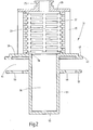
- the device has a designated as a whole with 1 filter housing, which consists of two parts of a housing upper part 3 in the form of a round bell and a lower closure member 5 which is screwed into the lower, open end of the upper part 3.
- the internally threaded end portion 7 of the upper part 3 engages over the connecting portion 9 of the lower part 5, so that in the screwed state, the end edge 11 of the closure member 5 is within the housing upper part 3 at a distance from the lower end.
- a sealing element 17 is arranged to the housing seal.
- the connection 15 is located at the top (viewing direction accordingly Fig.1 and 4 ) of the upper housing part 3 in a central position with respect to the vertical axis 21 of the device.
- the outlet connection 15 has an inner extension 23, which forms a kind of element receptacle in which a nozzle 25 with sealing element 27 can be accommodated.
- the nozzle 25 is located on an end plate 29 of a filter element, which in the Fig.2 and 3 shown separately and designated as a whole with 31. With the filter element 31 in the functional position, see Fig.1 and 3 , the outflow port 15 is via the port 25 in direct fluid communication with the inner filter cavity 33 of the filter element 31, which forms the clean side in the filtration.
- the filter element 31 which can be flowed through from the outside to the inner filter cavity 33 has a support structure for the hollow cylindrical filter medium 35 which forms a fluid-permeable support tube 37 which surrounds the inner filter cavity 33 and is surrounded on the outside by the filter medium 35.
- This support tube 37 extends from the upper end plate 29 to a disc 39, which, like the upper plate 29, forms a termination for the relevant end of the filter medium 35, but has a larger diameter than the end plate 29.
- the disc 29 has the form of an incomplete, ie interruption 41 (see Figure 3 ) having circular disk, 41 through these interruptions passages 43 ( Figure 4 ) are formed, which allow a medium flow through the disc 39.
- the disc 39 forms a step 47, which, when the filter element 31 is arranged in its functional position in the filter housing 1, abuts against an inner step 49 of the upper housing part 3 (s. Fig.1 ).
- the inner filter cavity 33 Via an opening 51 of the disc 39, the inner filter cavity 33, ie the clean side of the device in direct communication with a directly formed on the disc 39 cylindrical pot 53 with closed pot bottom 55.
- the pot 53 forms, as discussed later, a plenum , which designates here as the second collection space 36 is, for flowing out of the inner filter cavity 33 fluid, ie in the present case of oil droplets, which are deposited on the filter medium 35 by coalescence from the natural gas stream.
- a second disc 57 is integrally formed on the pot 53, which extends in a parallel plane to the first disc 39 and has a slightly smaller diameter than the latter.
- the second disk 57 like the first disk 39, has passages 59.
- the discs 39 and 57 act as dividing elements and define as upper wall or lower wall the inflow space 61 between them, in which the first stage of the deposition takes place.
- the Fig.1 and 4 show the filter element 31 in its installed functional position. When screwed into the upper housing part 3 closure part 5 this lies with its end edge 11 on the second disc 57 at. At the same time, the bottom 55 of the pot 53 is in abutment with the bottom part 13 of the closure part 5. As a result, the steps 47 and 49 on the upper disc 39 and the upper housing part 3 with each other in abutment and the nozzle 25 of the filter element 31 is in serving as an element receiving Extension 23 secured to the outlet connection 15. As the Fig. 1 and 4 show the housing inlet 19 opens with the designated inlet opening 63 so tangential to the inner wall 65 in the inflow space 61, that in this a swirl flow is generated.
- the phase separation takes place in the manner of a cyclone separator by centrifugal action.
- the thus separated fluid flows via the passages 59 of the lower disc 57 into the first collecting space 67, which surrounds the outside of the pot 53 in the closure part 5, which is held at its bottom 55 between centering bodies 69 protruding inwardly from the bottom region 13 of the closure part 5 ,
Landscapes
- Engineering & Computer Science (AREA)
- Chemical & Material Sciences (AREA)
- Chemical Kinetics & Catalysis (AREA)
- General Chemical & Material Sciences (AREA)
- Oil, Petroleum & Natural Gas (AREA)
- Combustion & Propulsion (AREA)
- Mechanical Engineering (AREA)
- General Engineering & Computer Science (AREA)
- Filtering Of Dispersed Particles In Gases (AREA)
- Separating Particles In Gases By Inertia (AREA)
- Cyclones (AREA)
Applications Claiming Priority (1)
| Application Number | Priority Date | Filing Date | Title |
|---|---|---|---|
| DE102011009232A DE102011009232A1 (de) | 2011-01-22 | 2011-01-22 | Vorrichtung zum Abscheiden von in gasförmigen Medien enthaltenen Fluiden, insbesondere Öl aus Gaskraftstoffen für Verbrennungsmotoren |
Publications (3)
| Publication Number | Publication Date |
|---|---|
| EP2478949A2 true EP2478949A2 (fr) | 2012-07-25 |
| EP2478949A3 EP2478949A3 (fr) | 2016-10-19 |
| EP2478949B1 EP2478949B1 (fr) | 2018-01-03 |
Family
ID=45558479
Family Applications (1)
| Application Number | Title | Priority Date | Filing Date |
|---|---|---|---|
| EP12000230.8A Active EP2478949B1 (fr) | 2011-01-22 | 2012-01-17 | Dispositif de séparation de fluides comprenant des milieux gazeux, notamment de l'huile à partir de carburants gazeux pour des moteurs à combustion interne |
Country Status (2)
| Country | Link |
|---|---|
| EP (1) | EP2478949B1 (fr) |
| DE (1) | DE102011009232A1 (fr) |
Cited By (1)
| Publication number | Priority date | Publication date | Assignee | Title |
|---|---|---|---|---|
| EP3027879A4 (fr) * | 2013-08-02 | 2017-11-08 | Alternative Fuel Containers, LLC | Unité de pré-filtre de gaz carburant de véhicule |
Families Citing this family (1)
| Publication number | Priority date | Publication date | Assignee | Title |
|---|---|---|---|---|
| DE102012017101A1 (de) | 2012-08-29 | 2014-05-15 | Hydac Process Technology Gmbh | Trennvorrichtung zum Abtrennen von Verschmutzungen aus Gasen |
Citations (1)
| Publication number | Priority date | Publication date | Assignee | Title |
|---|---|---|---|---|
| EP1884651B1 (fr) | 2006-08-01 | 2009-09-30 | GM Global Technology Operations, Inc. | Séparateur d'huile pour moteurs à combustion interne à gaz |
Family Cites Families (2)
| Publication number | Priority date | Publication date | Assignee | Title |
|---|---|---|---|---|
| JP2006083809A (ja) * | 2004-09-17 | 2006-03-30 | Yamaha Motor Co Ltd | エンジン駆動式乗り物用オイルタンク |
| CN201351587Y (zh) * | 2009-02-11 | 2009-11-25 | 绍兴瑞气压缩机有限公司 | 空压机用油气分离筒 |
-
2011
- 2011-01-22 DE DE102011009232A patent/DE102011009232A1/de not_active Withdrawn
-
2012
- 2012-01-17 EP EP12000230.8A patent/EP2478949B1/fr active Active
Patent Citations (1)
| Publication number | Priority date | Publication date | Assignee | Title |
|---|---|---|---|---|
| EP1884651B1 (fr) | 2006-08-01 | 2009-09-30 | GM Global Technology Operations, Inc. | Séparateur d'huile pour moteurs à combustion interne à gaz |
Cited By (2)
| Publication number | Priority date | Publication date | Assignee | Title |
|---|---|---|---|---|
| EP3027879A4 (fr) * | 2013-08-02 | 2017-11-08 | Alternative Fuel Containers, LLC | Unité de pré-filtre de gaz carburant de véhicule |
| US9933116B2 (en) | 2013-08-02 | 2018-04-03 | Alternative Fuel Containers, Llc | Vehicle fuel gas pre-filter unit |
Also Published As
| Publication number | Publication date |
|---|---|
| DE102011009232A1 (de) | 2012-07-26 |
| EP2478949B1 (fr) | 2018-01-03 |
| EP2478949A3 (fr) | 2016-10-19 |
Similar Documents
| Publication | Publication Date | Title |
|---|---|---|
| EP2308581B1 (fr) | Séparateur air-huile pour un compresseur d'air et installation de compression d'air | |
| EP3341109B1 (fr) | Dispositif de séparation | |
| EP2145099B1 (fr) | Dispositif d'amenée de carburant destiné en particulier à un moteur à combustion interne | |
| EP2663378B1 (fr) | Dispositif de filtration | |
| EP3641909B1 (fr) | Systeme de filtration avec elemente filtrant et elemente secondaire pour fermer un conduit central | |
| DE102013012918B4 (de) | Flüssigkeitsfilter und Filterelement, insbesondere für Kraftstoff | |
| EP3180131B1 (fr) | Dispositif pour le traitement de mélanges de fluides | |
| DE202014011016U1 (de) | Becherförmiges Gehäuse und Vorrichtung zum Abscheiden von Flüssigkeit aus Luft | |
| DE102015003165A1 (de) | Kraftstofffilter mit einem Kraftstofffiltereinsatz mit einem Vor- und einem Hauptfilterelement | |
| DE102011119868A1 (de) | Filtervorrichtung | |
| CH675278A5 (fr) | ||
| DE102015003162A1 (de) | Kraftstofffiltereinsatz mit einem Vor- und einem Hauptfilterelement sowie Kraftstofffilter | |
| EP1399240A2 (fr) | Element filtrant dote d'un tube de drainage | |
| EP2478949B1 (fr) | Dispositif de séparation de fluides comprenant des milieux gazeux, notamment de l'huile à partir de carburants gazeux pour des moteurs à combustion interne | |
| EP2255883A1 (fr) | Séparateur cyclonique | |
| WO2016146424A1 (fr) | Cartouche de filtre à carburant et filtre à carburant comprenant un élément de préfiltrage et un élément de filtrage principal ainsi qu'une unité de séparation d'eau | |
| DE202007003292U1 (de) | Ölabscheider mit mindestens einem Zyklon | |
| DE102014007302A1 (de) | Filtervorrichtung | |
| DE102016009487A1 (de) | Abscheideelement, Vorrichtung sowie Verfahren zur Abscheidung von Flüssigkeit aus Rohgas oder aus Rohgasgemisch einer Kraftmaschine/Kompressors | |
| DE102018110317A1 (de) | Filtersystem mit einem Filterelement | |
| DE102017001100A1 (de) | Fluidfilter mit einem Filtereinsatz mit einem Vor- und einem Hauptfilterelement | |
| WO2016146426A1 (fr) | Cartouche filtrante pour carburant comprenant un élément de filtration préalable et un élément de filtration principale et filtre à carburant | |
| EP3357555A1 (fr) | Élément de filtre à liquide et filtre à liquide pourvus de protection contre la corrosion pour pompes extérieures | |
| DE102022102039A1 (de) | Filtervorrichtung zum Filtern eines Fluids, Verwendung eines Filterelements in einer Filtervorrichtung, und Verfahren zum Austausch eines Filterelements | |
| DE102011002916A1 (de) | Fluidablasseinrichtung |
Legal Events
| Date | Code | Title | Description |
|---|---|---|---|
| PUAI | Public reference made under article 153(3) epc to a published international application that has entered the european phase |
Free format text: ORIGINAL CODE: 0009012 |
|
| AK | Designated contracting states |
Kind code of ref document: A2 Designated state(s): AL AT BE BG CH CY CZ DE DK EE ES FI FR GB GR HR HU IE IS IT LI LT LU LV MC MK MT NL NO PL PT RO RS SE SI SK SM TR |
|
| AX | Request for extension of the european patent |
Extension state: BA ME |
|
| PUAL | Search report despatched |
Free format text: ORIGINAL CODE: 0009013 |
|
| AK | Designated contracting states |
Kind code of ref document: A3 Designated state(s): AL AT BE BG CH CY CZ DE DK EE ES FI FR GB GR HR HU IE IS IT LI LT LU LV MC MK MT NL NO PL PT RO RS SE SI SK SM TR |
|
| AX | Request for extension of the european patent |
Extension state: BA ME |
|
| RIC1 | Information provided on ipc code assigned before grant |
Ipc: B01D 45/16 20060101ALI20160909BHEP Ipc: B01D 45/02 20060101AFI20160909BHEP Ipc: F02M 21/02 20060101ALI20160909BHEP Ipc: B01D 46/00 20060101ALI20160909BHEP |
|
| 17P | Request for examination filed |
Effective date: 20161025 |
|
| GRAP | Despatch of communication of intention to grant a patent |
Free format text: ORIGINAL CODE: EPIDOSNIGR1 |
|
| INTG | Intention to grant announced |
Effective date: 20170908 |
|
| GRAS | Grant fee paid |
Free format text: ORIGINAL CODE: EPIDOSNIGR3 |
|
| GRAA | (expected) grant |
Free format text: ORIGINAL CODE: 0009210 |
|
| REG | Reference to a national code |
Ref country code: FR Ref legal event code: PLFP Year of fee payment: 7 |
|
| AK | Designated contracting states |
Kind code of ref document: B1 Designated state(s): AL AT BE BG CH CY CZ DE DK EE ES FI FR GB GR HR HU IE IS IT LI LT LU LV MC MK MT NL NO PL PT RO RS SE SI SK SM TR |
|
| REG | Reference to a national code |
Ref country code: GB Ref legal event code: FG4D Free format text: NOT ENGLISH |
|
| REG | Reference to a national code |
Ref country code: CH Ref legal event code: EP Ref country code: AT Ref legal event code: REF Ref document number: 959706 Country of ref document: AT Kind code of ref document: T Effective date: 20180115 |
|
| REG | Reference to a national code |
Ref country code: IE Ref legal event code: FG4D Free format text: LANGUAGE OF EP DOCUMENT: GERMAN |
|
| REG | Reference to a national code |
Ref country code: DE Ref legal event code: R096 Ref document number: 502012011921 Country of ref document: DE |
|
| REG | Reference to a national code |
Ref country code: NL Ref legal event code: MP Effective date: 20180103 |
|
| REG | Reference to a national code |
Ref country code: LT Ref legal event code: MG4D |
|
| PG25 | Lapsed in a contracting state [announced via postgrant information from national office to epo] |
Ref country code: NL Free format text: LAPSE BECAUSE OF FAILURE TO SUBMIT A TRANSLATION OF THE DESCRIPTION OR TO PAY THE FEE WITHIN THE PRESCRIBED TIME-LIMIT Effective date: 20180103 |
|
| PG25 | Lapsed in a contracting state [announced via postgrant information from national office to epo] |
Ref country code: HR Free format text: LAPSE BECAUSE OF FAILURE TO SUBMIT A TRANSLATION OF THE DESCRIPTION OR TO PAY THE FEE WITHIN THE PRESCRIBED TIME-LIMIT Effective date: 20180103 Ref country code: ES Free format text: LAPSE BECAUSE OF FAILURE TO SUBMIT A TRANSLATION OF THE DESCRIPTION OR TO PAY THE FEE WITHIN THE PRESCRIBED TIME-LIMIT Effective date: 20180103 Ref country code: LT Free format text: LAPSE BECAUSE OF FAILURE TO SUBMIT A TRANSLATION OF THE DESCRIPTION OR TO PAY THE FEE WITHIN THE PRESCRIBED TIME-LIMIT Effective date: 20180103 Ref country code: CY Free format text: LAPSE BECAUSE OF FAILURE TO SUBMIT A TRANSLATION OF THE DESCRIPTION OR TO PAY THE FEE WITHIN THE PRESCRIBED TIME-LIMIT Effective date: 20180103 Ref country code: NO Free format text: LAPSE BECAUSE OF FAILURE TO SUBMIT A TRANSLATION OF THE DESCRIPTION OR TO PAY THE FEE WITHIN THE PRESCRIBED TIME-LIMIT Effective date: 20180403 Ref country code: FI Free format text: LAPSE BECAUSE OF FAILURE TO SUBMIT A TRANSLATION OF THE DESCRIPTION OR TO PAY THE FEE WITHIN THE PRESCRIBED TIME-LIMIT Effective date: 20180103 |
|
| PG25 | Lapsed in a contracting state [announced via postgrant information from national office to epo] |
Ref country code: IS Free format text: LAPSE BECAUSE OF FAILURE TO SUBMIT A TRANSLATION OF THE DESCRIPTION OR TO PAY THE FEE WITHIN THE PRESCRIBED TIME-LIMIT Effective date: 20180503 Ref country code: GR Free format text: LAPSE BECAUSE OF FAILURE TO SUBMIT A TRANSLATION OF THE DESCRIPTION OR TO PAY THE FEE WITHIN THE PRESCRIBED TIME-LIMIT Effective date: 20180404 Ref country code: PL Free format text: LAPSE BECAUSE OF FAILURE TO SUBMIT A TRANSLATION OF THE DESCRIPTION OR TO PAY THE FEE WITHIN THE PRESCRIBED TIME-LIMIT Effective date: 20180103 Ref country code: RS Free format text: LAPSE BECAUSE OF FAILURE TO SUBMIT A TRANSLATION OF THE DESCRIPTION OR TO PAY THE FEE WITHIN THE PRESCRIBED TIME-LIMIT Effective date: 20180103 Ref country code: SE Free format text: LAPSE BECAUSE OF FAILURE TO SUBMIT A TRANSLATION OF THE DESCRIPTION OR TO PAY THE FEE WITHIN THE PRESCRIBED TIME-LIMIT Effective date: 20180103 Ref country code: LV Free format text: LAPSE BECAUSE OF FAILURE TO SUBMIT A TRANSLATION OF THE DESCRIPTION OR TO PAY THE FEE WITHIN THE PRESCRIBED TIME-LIMIT Effective date: 20180103 Ref country code: BG Free format text: LAPSE BECAUSE OF FAILURE TO SUBMIT A TRANSLATION OF THE DESCRIPTION OR TO PAY THE FEE WITHIN THE PRESCRIBED TIME-LIMIT Effective date: 20180403 |
|
| REG | Reference to a national code |
Ref country code: CH Ref legal event code: PL |
|
| PG25 | Lapsed in a contracting state [announced via postgrant information from national office to epo] |
Ref country code: MT Free format text: LAPSE BECAUSE OF FAILURE TO SUBMIT A TRANSLATION OF THE DESCRIPTION OR TO PAY THE FEE WITHIN THE PRESCRIBED TIME-LIMIT Effective date: 20180103 |
|
| REG | Reference to a national code |
Ref country code: DE Ref legal event code: R097 Ref document number: 502012011921 Country of ref document: DE |
|
| PG25 | Lapsed in a contracting state [announced via postgrant information from national office to epo] |
Ref country code: LU Free format text: LAPSE BECAUSE OF NON-PAYMENT OF DUE FEES Effective date: 20180117 Ref country code: IT Free format text: LAPSE BECAUSE OF FAILURE TO SUBMIT A TRANSLATION OF THE DESCRIPTION OR TO PAY THE FEE WITHIN THE PRESCRIBED TIME-LIMIT Effective date: 20180103 Ref country code: AL Free format text: LAPSE BECAUSE OF FAILURE TO SUBMIT A TRANSLATION OF THE DESCRIPTION OR TO PAY THE FEE WITHIN THE PRESCRIBED TIME-LIMIT Effective date: 20180103 Ref country code: MC Free format text: LAPSE BECAUSE OF FAILURE TO SUBMIT A TRANSLATION OF THE DESCRIPTION OR TO PAY THE FEE WITHIN THE PRESCRIBED TIME-LIMIT Effective date: 20180103 Ref country code: EE Free format text: LAPSE BECAUSE OF FAILURE TO SUBMIT A TRANSLATION OF THE DESCRIPTION OR TO PAY THE FEE WITHIN THE PRESCRIBED TIME-LIMIT Effective date: 20180103 Ref country code: RO Free format text: LAPSE BECAUSE OF FAILURE TO SUBMIT A TRANSLATION OF THE DESCRIPTION OR TO PAY THE FEE WITHIN THE PRESCRIBED TIME-LIMIT Effective date: 20180103 |
|
| REG | Reference to a national code |
Ref country code: IE Ref legal event code: MM4A |
|
| REG | Reference to a national code |
Ref country code: BE Ref legal event code: MM Effective date: 20180131 |
|
| PLBE | No opposition filed within time limit |
Free format text: ORIGINAL CODE: 0009261 |
|
| STAA | Information on the status of an ep patent application or granted ep patent |
Free format text: STATUS: NO OPPOSITION FILED WITHIN TIME LIMIT |
|
| PG25 | Lapsed in a contracting state [announced via postgrant information from national office to epo] |
Ref country code: DK Free format text: LAPSE BECAUSE OF FAILURE TO SUBMIT A TRANSLATION OF THE DESCRIPTION OR TO PAY THE FEE WITHIN THE PRESCRIBED TIME-LIMIT Effective date: 20180103 Ref country code: LI Free format text: LAPSE BECAUSE OF NON-PAYMENT OF DUE FEES Effective date: 20180131 Ref country code: CZ Free format text: LAPSE BECAUSE OF FAILURE TO SUBMIT A TRANSLATION OF THE DESCRIPTION OR TO PAY THE FEE WITHIN THE PRESCRIBED TIME-LIMIT Effective date: 20180103 Ref country code: SK Free format text: LAPSE BECAUSE OF FAILURE TO SUBMIT A TRANSLATION OF THE DESCRIPTION OR TO PAY THE FEE WITHIN THE PRESCRIBED TIME-LIMIT Effective date: 20180103 Ref country code: CH Free format text: LAPSE BECAUSE OF NON-PAYMENT OF DUE FEES Effective date: 20180131 Ref country code: SM Free format text: LAPSE BECAUSE OF FAILURE TO SUBMIT A TRANSLATION OF THE DESCRIPTION OR TO PAY THE FEE WITHIN THE PRESCRIBED TIME-LIMIT Effective date: 20180103 Ref country code: BE Free format text: LAPSE BECAUSE OF NON-PAYMENT OF DUE FEES Effective date: 20180131 |
|
| 26N | No opposition filed |
Effective date: 20181005 |
|
| PG25 | Lapsed in a contracting state [announced via postgrant information from national office to epo] |
Ref country code: IE Free format text: LAPSE BECAUSE OF NON-PAYMENT OF DUE FEES Effective date: 20180117 |
|
| PG25 | Lapsed in a contracting state [announced via postgrant information from national office to epo] |
Ref country code: SI Free format text: LAPSE BECAUSE OF FAILURE TO SUBMIT A TRANSLATION OF THE DESCRIPTION OR TO PAY THE FEE WITHIN THE PRESCRIBED TIME-LIMIT Effective date: 20180103 |
|
| REG | Reference to a national code |
Ref country code: AT Ref legal event code: MM01 Ref document number: 959706 Country of ref document: AT Kind code of ref document: T Effective date: 20180117 |
|
| PG25 | Lapsed in a contracting state [announced via postgrant information from national office to epo] |
Ref country code: AT Free format text: LAPSE BECAUSE OF NON-PAYMENT OF DUE FEES Effective date: 20180117 |
|
| PG25 | Lapsed in a contracting state [announced via postgrant information from national office to epo] |
Ref country code: TR Free format text: LAPSE BECAUSE OF FAILURE TO SUBMIT A TRANSLATION OF THE DESCRIPTION OR TO PAY THE FEE WITHIN THE PRESCRIBED TIME-LIMIT Effective date: 20180103 |
|
| PG25 | Lapsed in a contracting state [announced via postgrant information from national office to epo] |
Ref country code: PT Free format text: LAPSE BECAUSE OF FAILURE TO SUBMIT A TRANSLATION OF THE DESCRIPTION OR TO PAY THE FEE WITHIN THE PRESCRIBED TIME-LIMIT Effective date: 20180103 Ref country code: HU Free format text: LAPSE BECAUSE OF FAILURE TO SUBMIT A TRANSLATION OF THE DESCRIPTION OR TO PAY THE FEE WITHIN THE PRESCRIBED TIME-LIMIT; INVALID AB INITIO Effective date: 20120117 |
|
| PG25 | Lapsed in a contracting state [announced via postgrant information from national office to epo] |
Ref country code: MK Free format text: LAPSE BECAUSE OF NON-PAYMENT OF DUE FEES Effective date: 20180103 |
|
| PGFP | Annual fee paid to national office [announced via postgrant information from national office to epo] |
Ref country code: GB Payment date: 20231101 Year of fee payment: 13 |
|
| PGFP | Annual fee paid to national office [announced via postgrant information from national office to epo] |
Ref country code: FR Payment date: 20231127 Year of fee payment: 13 |
|
| PGFP | Annual fee paid to national office [announced via postgrant information from national office to epo] |
Ref country code: DE Payment date: 20240131 Year of fee payment: 13 |