EP2478794B1 - Tragevorrichtung mit mobilem Gurt - Google Patents
Tragevorrichtung mit mobilem Gurt Download PDFInfo
- Publication number
- EP2478794B1 EP2478794B1 EP20120152336 EP12152336A EP2478794B1 EP 2478794 B1 EP2478794 B1 EP 2478794B1 EP 20120152336 EP20120152336 EP 20120152336 EP 12152336 A EP12152336 A EP 12152336A EP 2478794 B1 EP2478794 B1 EP 2478794B1
- Authority
- EP
- European Patent Office
- Prior art keywords
- waist belt
- belt
- carrying device
- rear wall
- user
- Prior art date
- Legal status (The legal status is an assumption and is not a legal conclusion. Google has not performed a legal analysis and makes no representation as to the accuracy of the status listed.)
- Active
Links
- 239000000463 material Substances 0.000 claims description 6
- 239000004753 textile Substances 0.000 claims description 6
- 238000010521 absorption reaction Methods 0.000 claims 1
- 210000004197 pelvis Anatomy 0.000 description 10
- 241000287107 Passer Species 0.000 description 9
- 238000006073 displacement reaction Methods 0.000 description 3
- 210000001624 hip Anatomy 0.000 description 3
- 238000011084 recovery Methods 0.000 description 3
- 210000004394 hip joint Anatomy 0.000 description 2
- 210000002414 leg Anatomy 0.000 description 2
- 238000000034 method Methods 0.000 description 2
- 208000031968 Cadaver Diseases 0.000 description 1
- 230000009194 climbing Effects 0.000 description 1
- 238000010586 diagram Methods 0.000 description 1
- 230000000977 initiatory effect Effects 0.000 description 1
- 210000001503 joint Anatomy 0.000 description 1
- 210000004072 lung Anatomy 0.000 description 1
- 238000012423 maintenance Methods 0.000 description 1
- 238000004519 manufacturing process Methods 0.000 description 1
- 230000010355 oscillation Effects 0.000 description 1
- 230000035479 physiological effects, processes and functions Effects 0.000 description 1
- 235000020004 porter Nutrition 0.000 description 1
- 230000029058 respiratory gaseous exchange Effects 0.000 description 1
- 238000005096 rolling process Methods 0.000 description 1
- 238000009958 sewing Methods 0.000 description 1
- 238000010008 shearing Methods 0.000 description 1
- 210000000323 shoulder joint Anatomy 0.000 description 1
Images


Classifications
-
- A—HUMAN NECESSITIES
- A45—HAND OR TRAVELLING ARTICLES
- A45F—TRAVELLING OR CAMP EQUIPMENT: SACKS OR PACKS CARRIED ON THE BODY
- A45F3/00—Travelling or camp articles; Sacks or packs carried on the body
- A45F3/04—Sacks or packs carried on the body by means of two straps passing over the two shoulders
- A45F3/047—Sacks or packs carried on the body by means of two straps passing over the two shoulders with adjustable fastenings for the shoulder straps or waist belts
Definitions
- the present invention relates to a carrying device, and more particularly to a device for carrying a load such as a backpack for example.
- Generally known carrying devices comprise a backrest intended to bear against the back of a user and extending longitudinally between an upper end and a lower end. In order to resume the carrying efforts, these devices most often comprise straps intended to connect the backrest to the shoulders of the user, and a belt connected by means of attachment to the file and intended to gird the size of the user. This belt is usually fixed relative to the folder.
- the belt surrounding the size of the user undergoes constraints that tend to move it relative to the user.
- the belt tends to rise due to the lengthening of the distance shoulder / pelvis, sometimes even up to the level of the floating ribs of the user, which then hinders the breathing movements of the latter by limiting the allowable air volume in the lungs.
- the user In order to limit this movement of the belt, the user generally tends to tighten the belt substantially around his waist. But too much tightness hurts the user's flesh compressed by the belt. And this clamping still does not prevent the belt from moving relative to the user during tilting movements of the column relative to the pelvis in the frontal plane of the user and during tilting movements of the spine of the user in the sagittal plane.
- Too much tightening of the belt also generally leads to a relative movement of clothing relative to the body of the user at its height, most often leading to the user's shirt being pulled out his pants and then to form folds and folds by rolling and roving of the shirt which then also mark the flesh of the user.
- a first problem proposed by the invention is to ensure, in a simple, economical and practical way, the maintenance of a reliable positioning of the belt of a device for carrying a load around the size of a user, and this during all the physiological movements caused by the progression of the user during a walk or a run for example.
- a second problem proposed by the invention is to make the belt secured to the backrest by light and compact means of fixing so as not to unnecessarily increase the weight of the vacuum carrying device and not to hinder the user in his movements .
- the backrest can move in translation and rotation relative to the belt, the belt does not tend to rise when extending the distance shoulder / pelvis.
- Such a device makes it possible to maintain the belt at a determined location around the size of the user without it moving during the various physiological movements occasioned by the progression of the user in various and varied modes such as the walking, climbing or running. In particular, a rise of the belt is avoided at the level of the user's floating ribs.
- the belt can thus be tightened reasonably on the hips of the user who, generally having a substantially frustoconical shape that comes to marry the belt, allow to take part of the carrying efforts via the belt.
- the fixing means according to the invention are simple and effective to allow movement of the belt in translation relative to the backrest.
- Such fastening means are light and compact, very thin in particular, so as not to hinder the user and not to unnecessarily increase the weight of the vacuum bag.
- the user's hips can take up at least a portion of the carrying forces via the belt.
- the high and low positions of the belt may be distant from a height of between about 3 cm and about 20 cm, preferably about 10 cm.
- Such a height corresponds substantially to the average elongation of the shoulder / pelvis distance of the majority of users, taken along the back, when the user leans his trunk or bust forward to tilt relative to the vertical.
- the rotation of the belt relative to the longitudinal direction can be limited, and is preferably performed at a maximum inclination angle of between about 100 ° and about 115 °.
- Restricting rotational movements of the belt avoids uncomfortable movements beyond physiologically acceptable movements. It also avoids too much instability of the load on the back of the user who could unbalance it.
- Such a location means fastening the belt to the backrest allows detachment of the lower edge of the belt away from the backrest when the user leans the upper part of his body (trunk or bust) forward, while his legs remain substantially vertical. This avoids shearing the size of the user by the lower part of the belt coming on the front of the size of the user.
- the belt may have, in the vicinity of the fastening means, a height of between about 10 cm and about 17 cm.
- the passer can receive the intermediate portion with a game according to the width of the rod, which game allows a displacement of the belt in rotation relative to the backrest simply and effectively.
- the rod and / or the passer may be made of a flexible or sufficiently deformable material to allow rotation of the belt relative to the backrest.
- the two rods can be separated from each other by a distance of between about 10 cm and about 20 cm.
- Such a distance makes it possible to ensure a good stability of the load without preventing the belt from marrying at best the size of the user whose back width can vary according to the build of the user.
- said at least one rod and said at least one passer can be textile straps, said rod being preferably reinforced by a stiffening element.
- the production of textile material fastening means is inexpensive, but also reliable by the use of textile products such as straps whose resistance can be considerable.
- the stiffening of said at least one rod makes it possible to limit any inadvertent spacing movement of the belt away from the backrest at the level of the fixing means and also makes it possible to better oppose a relative movement between the belt and the backrest. in a direction perpendicular to the longitudinal direction and included for example in the front plane of the user.
- the carrying device may comprise amplitude adjustment means for adjusting the amplitude of the translation and rotation movements of the belt relative to the backrest, the amplitude adjustment means preferably comprising at least one strap. , adjustable in length, connected at one of its ends to the belt, and connected to the other of its ends to the folder.
- the amplitude adjustment means make it possible to adapt the amplitude of the translational and rotational movements to the physiological capacities of each of the users in order to allow only movements having a strictly necessary amplitude. Beyond this necessary amplitude, resistance occurs against translation and / or rotation movements, which which stabilizes the load on the back of the user, to prevent it from moving beyond a certain point that could risk in the long run to unbalance the user, or to hurt him.
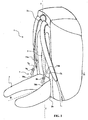
- FIG. 1 to 11 illustrate a preferred embodiment of the present invention.
- a carrier device 1 of the backpack type having a backrest 2 intended to bear against the back of a user and extending longitudinally in the longitudinal direction II between an upper end 2a and a lower end 2b .
- the carrying device 1 comprises a belt 3 connected by fastening means 4 ( Figures 6 to 9 ) Folder 2 and intended to gird the user's size.
- the lower end 2b of the backrest 2 is intended to come indirectly in abutment against the back of the user via the belt 3.
- the fixing means 4 ( Figures 6 to 9 ) are shaped so as to allow movement of the belt 3 in translation relative to the backrest 2 in the longitudinal direction II between a high position ( figures 2 and 7 ) and a low position ( figures 3 and 6 ).
- fastening means 4 are shaped so as to allow a movement of the belt 3 in rotation with respect to the backrest 2 about a direction II-II substantially perpendicular to the backrest 2.
- the fixing means 4 allow the movements of the Figures 2 to 5 to occur simultaneously or independently.
- a possible structure of the fixing means 4 is more particularly illustrated on the Figures 6 to 9 where only the belt 3 is shown solid lines, the other elements of the carrying device 1 being shown in dotted lines or not shown to facilitate understanding of the disclosure of the invention.
- the structure of the fastening means 4 allows a displacement in translation of the belt 3 with respect to the backrest 2 in the longitudinal direction II between a high position ( figures 2 and 7 ) and a low position ( figures 3 and 6 ), the belt moving a height h1.
- the rods 4a, 4b and the loops 5a, 5b are situated on either side of the longitudinal direction II while being separated by a distance d ( Figures 6 and 7 ) to oppose oscillation movements of the bag around the longitudinal direction II.
- the loops 5a and 5b receive the intermediate sections 42a and 42b with a greater or lesser clearance depending on the width of the rods 4a and 4b, as it is more particularly visible on the Figures 6 and 7 .
- Passers 5a and 5b have indeed a passage of width L greater than the width l of the rods 4a and 4b. This game allows a displacement of the belt 3 in rotation with respect to the backrest 2 around the direction II-II substantially perpendicular to the backrest 2 ( Figures 8 and 9 ).
- stop means 6 are constituted by the connection (by sewing for example) of the ends 40a and 40b of the rods 4a and 4b with the backrest 2.
- the high and low positions of the belt 3 are defined by the length of the rods 4a and 4b.
- the high and low positions of the belt 3 are distant from a height h1 ( Figures 2, 3 , 6 and 7 ) between about 3 cm and about 20 cm, preferably 10 cm.
- the possible angle of rotation of the belt relative to the longitudinal direction is determined by the clearance between the width of the rods 4a and 4b and the loops 5a and 5b, the height h2 of the loops 5a and 5b, and by the rigidity of the materials constituting the loops 5a and 5b and the rods 4a and 4b.
- the belt 3 extends in height, in the vicinity of the fastening means 4, between an upper edge 3a and a lower edge 3b. And we see more particularly the Figures 6 to 9 that the fastening means of the belt 3 to the backrest 2 are located near the upper edge 3a of the belt 3.
- Such an arrangement of the fastening means 4 allows detachment of the belt 3 at its lower edge 3b away from the backrest 2 when the user leans forward the upper part of his body (bust or trunk) with respect to the vertical III-III, as it is more particularly illustrated on the Figures 10 and 11 .
- the user stands straight and at rest with the belt 3 in the high position, that is to say that the belt 3 is in abutment against the abutment means 6.
- the belt 3 allows partial recovery of the carrying forces .
- the shoulder / pelvis or hip-hip / shoulder joint lengthens due to the relative inclination of the upper body of the user relative to the vertical III-III as it is more particularly illustrated on the figure 11 .
- the upper body of the user makes an angle ⁇ with the vertical direction III-III.
- the carrying device 1 then moves from the position shown in dotted lines to the position shown in solid lines. It can be seen that, because of the lengthening of the shoulder / pelvis distance along the back of the user, the belt 3 has moved in translation relative to the backrest 2 and the lower edge 3b of the belt 3 is away from the backrest 2. The belt 3 remains motionless on the size of the user.
- the belt 3 has a height h3 between about 10 cm and about 17 cm in the vicinity of the fastening means 4 ( Figures 2, 3 , 6 and 7 ).
- the fixing means 4 comprise two rods 4a and 4b.
- the two rods 4a and 4b are separated from each other by a distance d of between about 10 cm and about 20 cm.
- the rods 4a and 4b and the loops 5a and 5b are based on textile straps.
- the rods 4a and 4b are preferably reinforced by an internal stiffening element preventing the loops 5a and 5b from moving away from the backrest 2.
- the carrying device 1 further comprises amplitude adjustment means 7 for adjusting the amplitude of the translational and rotational movements of the belt 3 relative to the backrest 2.
- the amplitude means 7 comprise two straps 7a and 7b adjustable in length and connected to one of their ends 70a and 70b to the belt 3 and connected to the other of their ends 71a and 71b in the file 2.
- the amplitudes of the translational and rotational movements of the belt 3 are thus adaptable to the physical capacity of the user and to the circumstances of use of the carrying device 1.
- the belt 3 In the rest position, when the user is vertical as shown in the figure 10 , the belt 3 is substantially in the position illustrated on the figure 7 (high position) with the loops 5a and 5b bearing against the abutment means 6. Part of the carrying forces is then taken up by the belt 3.
- the user slightly inclines his bust or trunk forward in the sagittal plane as shown in the diagram. figure 11 .
- the belt 3 then moves relative to the backrest 2 to the low position ( figure 6 ) by the sliding rods 4a and 4b in the loops 5a and 5b.
- the load is then carried mainly by the shoulders of the user.
- the user tends to straighten in the position of the figure 10 which brings the belt 3 back to the high position ( figure 7 ).
- one of the loops 5a or 5b moves away from the stop means 6 while the other 5a or 5b remains in contact with the abutment means 6.
- the belt 3 s thus inclines at an angle ⁇ 1 or ⁇ 2 with respect to the longitudinal direction II to follow the movements of the pelvis relative to the longitudinal direction II which corresponds to the direction of the spine of the user.
- the passer 5a or 5b which remains in abutment against the abutment means 6 allows the belt 3 to take up at least part of the carrying forces.
Landscapes
- Portable Outdoor Equipment (AREA)
- Orthopedics, Nursing, And Contraception (AREA)
Claims (12)
- Tragvorrichtung (1) für eine Last, umfassend eine Rückenstütze (2), die zur Abstützung am Rücken eines Benutzers dient und sich in Längsrichtung zwischen einem oberen Ende (2a) und einem unteren Ende (2b) erstreckt, sowie einen Gürtel (3), der über Befestigungsmittel (4) mit der Rückenstütze (2) verbunden und dazu ausgebildet ist, die Taille des Benutzers zu umfassen, wobei:- die Befestigungsmittel (4) so ausgebildet sind, dass sie eine Verschiebebewegung des Gürtels (3) relativ zu der Rückenstütze (2) in Längsrichtung (I - I) zwischen einer oberen und einer unteren Position ermöglichen,- die Befestigungsmittel (4) so ausgebildet sind, dass sie eine Drehbewegung des Gürtels (3) relativ zu der Rückenstütze (2) um eine Drehachse (II - II) ermöglichen, die im wesentlichen rechtwinklig zur Rückenstütze (2) verläuft,
dadurch gekennzeichnet, dass die Befestigungsmittel (4) umfassen:- wenigstens eine Stange (4a, 4b), die sich in der Längsrichtung (I - I) erstreckt, an ihren beiden Enden (40a, 41a, 40b, 41b) an der Rückenstütze (2) befestigt ist und einen freien Zwischenabschnitt (42a, 42b) aufweist,- wenigstens eine an dem Gürtel (3) fest verbundene Schlaufe (5a, 5b), die dazu dient, den freien Zwischenabschnitt (42a, 42b) der wenigstens einen Stange (4a, 4b) verschiebbar aufzunehmen. - Tragvorrichtung (1) nach Anspruch 1, dadurch gekennzeichnet, dass die Schlaufe (5a, 5b) den Zwischenabschnitt (42a, 42b) mit einem der Breite der Stange (4a, 4b) entsprechenden Spiel aufnimmt.
- Tragvorrichtung (1) nach Anspruch 1 oder 2, dadurch gekennzeichnet, dass die Drehung des Gürtels (3) relativ zu der Rückenstütze (2) durch die Flexibilität oder Verformbarkeit des Werkstoffs oder der Werkstoffe ermöglicht wird, aus denen die wenigstens eine Stange (4a, 4b) und/oder die wenigstens einen Schlaufe (5a, 5b) besteht.
- Tragvorrichtung (1) nach einem der Ansprüche 1 bis 3, dadurch gekennzeichnet, dass die Befestigungsmittel (4) umfassen:- zwei Stangen (4a, 4b), die sich in Längsrichtung (I - I) erstrecken, mit ihren entsprechenden Enden (40a, 41 a, 40b, 41 b) an der Rückenstütze (2) befestigt sind und jede einen freien Zwischenabschnitt (42a, 42b) hat,- zwei mit dem Gürtel (3) fest verbundene Schlaufen (5a, 5b) zur entsprechende verschiebbaren Aufnahme der freien Zwischenabschnitte (42a, 42b) der beiden Stangen (4a, 4b).
- Tragvorrichtung (1) nach Anspruch 4, dadurch gekennzeichnet, dass die beiden Stangen (4a, 4b) voneinander durch einen Abstand (d) zwischen ungefähr lOcm und ungefähr 20 cm getrennt sind.
- Tragvorrichtung (1) nach einem der Ansprüche 1 bis 5, dadurch gekennzeichnet, dass die wenigstens eine Stange (4a, 4b) und die wenigstens eine Schlaufe (5a, 5b) aus textilen Gurten bestehenden, wobei die Stange (4a, 4b) vorzugsweise durch ein Versteifungselement verstärkt ist.
- Tragvorrichtung (1) nach einem der Ansprüche 1 bis 6, dadurch gekennzeichnet, dass:- die Rückenstütze (2) Anschlagmittel (6) hat, an denen sich der Gürtel (3) in seiner oberen Stellung abstützt,- die Anschlagmittel (6) so ausgebildet sind, dass sie wenigstens eine teilweise Aufnahme der Traglasten des Gürtels (3) bewirken.
- Tragvorrichtung (1) nach einem der Ansprüche 1 bis 7, dadurch gekennzeichnet, dass die obere und die untere Stellung des Gürtels (3) über eine Höhe (h1) zwischen etwa 3 cm und etwa 20 cm, vorzugsweise etwa 10 cm voneinander beabstandet sind.
- Tragvorrichtung (1) nach einem der Ansprüche 1 bis 8, dadurch gekennzeichnet, dass die Drehbewegung des Gürtels (3) um die Längsrichtung (I - I) begrenzt ist und vorzugweise sich über einen maximalen Neigungswinkel (α1, α2) zwischen etwa 100° und etwa 115° erstreckt.
- Tragvorrichtung (1) nach einem der Ansprüche 1 bis 9, dadurch gekennzeichnet, dass:- sich der Gürtel (3) in der Nähe der Befestigungsmittel (4) in der Höhe (h3) zwischen einem oberen Rand (3a) und einem unteren Rand (3b) erstreckt,- die Befestigungsmittel (4) des Gürtels (3) an der Rückenstütze (2) in der Nähe des oberen Randes (3a) des Gürtels (3) angeordnet sind.
- Tragvorrichtung (1) nach Anspruch 10, dadurch gekennzeichnet, dass der Gürtel (3) in der Nähe der Befestigungsmittel (4) eine Höhe (h3) zwischen etwa 10 cm und etwa 17 cm hat.
- Tragvorrichtung (1) nach einem der Ansprüche 1 bis 11, dadurch gekennzeichnet, dass sie Amplituden-Einstellmittel (7) zum Einstellen der Amplitude der Verschiebebewegung und der Drehbewegung des Gürtels (3) relativ zur Rückenstütze (2) aufweist, wobei die Einstellmittel (7) vorzugsweise wenigstens einen längenverstellbaren Gurt (7a, 7b) umfassen, der mit einem seiner Enden (70a, 70b) mit dem Gürtel (3) und mit seinem anderen Ende (71a, 71 b) mit der Rückenstütze (2) verbunden ist.
Applications Claiming Priority (1)
| Application Number | Priority Date | Filing Date | Title |
|---|---|---|---|
| FR1150585A FR2970628B1 (fr) | 2011-01-25 | 2011-01-25 | Dispositif de portage a ceinture mobile |
Publications (2)
| Publication Number | Publication Date |
|---|---|
| EP2478794A1 EP2478794A1 (de) | 2012-07-25 |
| EP2478794B1 true EP2478794B1 (de) | 2014-04-09 |
Family
ID=44243563
Family Applications (1)
| Application Number | Title | Priority Date | Filing Date |
|---|---|---|---|
| EP20120152336 Active EP2478794B1 (de) | 2011-01-25 | 2012-01-24 | Tragevorrichtung mit mobilem Gurt |
Country Status (2)
| Country | Link |
|---|---|
| EP (1) | EP2478794B1 (de) |
| FR (1) | FR2970628B1 (de) |
Families Citing this family (1)
| Publication number | Priority date | Publication date | Assignee | Title |
|---|---|---|---|---|
| FR3057484B1 (fr) | 2016-10-14 | 2018-11-30 | Bmexo | Dispositif portable de support de charge eloignee de la personne qui la porte |
Family Cites Families (3)
| Publication number | Priority date | Publication date | Assignee | Title |
|---|---|---|---|---|
| FR2739004B1 (fr) * | 1995-09-22 | 1997-10-31 | Decathlon Sa | Sac a dos pourvu de moyens de portage ameliores |
| CA2519133C (en) * | 2003-03-14 | 2012-08-28 | The North Face Apparel Corp. | Backpack suspension system |
| NO322177B1 (no) * | 2005-01-13 | 2006-08-21 | Bergans Fritid As | Opplagring av et hoftebelte til en ryggsekk |
-
2011
- 2011-01-25 FR FR1150585A patent/FR2970628B1/fr not_active Expired - Fee Related
-
2012
- 2012-01-24 EP EP20120152336 patent/EP2478794B1/de active Active
Also Published As
| Publication number | Publication date |
|---|---|
| FR2970628B1 (fr) | 2013-07-05 |
| FR2970628A1 (fr) | 2012-07-27 |
| EP2478794A1 (de) | 2012-07-25 |
Similar Documents
| Publication | Publication Date | Title |
|---|---|---|
| EP0630805B1 (de) | Schwimmende Krankentrage, insbesondere zur Rettung Veletzter auf See | |
| FR2946237A1 (fr) | Sac a dos tel qu'un sac a dos d'hydratation | |
| FR2644692A1 (fr) | Orthese pour la reduction tridimensionnelle des scolioses | |
| FR3086588A1 (fr) | Selles de velo | |
| EP3585346A1 (de) | Rollstuhl zur gehunterstützung | |
| CA3009549A1 (fr) | Module de pied pour une structure d'exosquelette | |
| US20140008149A1 (en) | Tree stand | |
| EP3037015A1 (de) | Rucksack | |
| EP3106061A1 (de) | Trageartikel | |
| FR2607375A1 (fr) | Fauteuil ou analogue, fixe ou mobile, comportant une structure de verticalisation | |
| EP2478794B1 (de) | Tragevorrichtung mit mobilem Gurt | |
| EP3903756B1 (de) | Orthopädische gehhilfevorrichtung, die zur rehabilitation des gehvermögens verwendet werden kann und mittel zum spreizen der oberschenkel des patienten umfasst | |
| EP3507175B1 (de) | Sitz, insbesondere für ein fahrrad | |
| US8136873B2 (en) | Foldable rest support | |
| WO2012066252A1 (fr) | Armature d'equilibrage pour sac a dos | |
| EP2094205B1 (de) | Vorrichtung für lordosestütze des rückens zur haltungskorrektur | |
| FR2745697A1 (fr) | Support dorsal pour machine portative entrainee par moteur | |
| EP3598961A1 (de) | Orthopädische gehhilfevorrichtung | |
| WO2018104595A1 (fr) | Dispositif d'appui antérieur pour les membres inférieurs | |
| EP3801136B1 (de) | Physiologische sitzvorrichtung | |
| FR3028734A1 (fr) | Dispositif et ensemble de portage d'une charge par un utilisateur | |
| FR3020750A1 (fr) | Dispositif de maintien corporel en position debout | |
| WO1989006506A1 (fr) | Siege s'adaptant aux attitudes morphologiques de l'utilisateur | |
| EP2545803A1 (de) | Rucksack mit Zugbändern | |
| FR2926216A1 (fr) | Cadre de marche securise |
Legal Events
| Date | Code | Title | Description |
|---|---|---|---|
| PUAI | Public reference made under article 153(3) epc to a published international application that has entered the european phase |
Free format text: ORIGINAL CODE: 0009012 |
|
| AK | Designated contracting states |
Kind code of ref document: A1 Designated state(s): AL AT BE BG CH CY CZ DE DK EE ES FI FR GB GR HR HU IE IS IT LI LT LU LV MC MK MT NL NO PL PT RO RS SE SI SK SM TR |
|
| AX | Request for extension of the european patent |
Extension state: BA ME |
|
| 17P | Request for examination filed |
Effective date: 20121217 |
|
| GRAP | Despatch of communication of intention to grant a patent |
Free format text: ORIGINAL CODE: EPIDOSNIGR1 |
|
| RIC1 | Information provided on ipc code assigned before grant |
Ipc: A45F 3/04 20060101AFI20130930BHEP |
|
| INTG | Intention to grant announced |
Effective date: 20131022 |
|
| GRAS | Grant fee paid |
Free format text: ORIGINAL CODE: EPIDOSNIGR3 |
|
| GRAA | (expected) grant |
Free format text: ORIGINAL CODE: 0009210 |
|
| RIN1 | Information on inventor provided before grant (corrected) |
Inventor name: MENETRIER, MARC |
|
| AK | Designated contracting states |
Kind code of ref document: B1 Designated state(s): AL AT BE BG CH CY CZ DE DK EE ES FI FR GB GR HR HU IE IS IT LI LT LU LV MC MK MT NL NO PL PT RO RS SE SI SK SM TR |
|
| REG | Reference to a national code |
Ref country code: GB Ref legal event code: FG4D Free format text: NOT ENGLISH |
|
| REG | Reference to a national code |
Ref country code: AT Ref legal event code: REF Ref document number: 660830 Country of ref document: AT Kind code of ref document: T Effective date: 20140415 Ref country code: CH Ref legal event code: EP |
|
| REG | Reference to a national code |
Ref country code: IE Ref legal event code: FG4D Free format text: LANGUAGE OF EP DOCUMENT: FRENCH |
|
| REG | Reference to a national code |
Ref country code: DE Ref legal event code: R096 Ref document number: 602012001321 Country of ref document: DE Effective date: 20140522 |
|
| REG | Reference to a national code |
Ref country code: CH Ref legal event code: NV Representative=s name: WAGNER PATENT AG, CH |
|
| REG | Reference to a national code |
Ref country code: AT Ref legal event code: MK05 Ref document number: 660830 Country of ref document: AT Kind code of ref document: T Effective date: 20140409 |
|
| REG | Reference to a national code |
Ref country code: NL Ref legal event code: VDEP Effective date: 20140409 |
|
| REG | Reference to a national code |
Ref country code: LT Ref legal event code: MG4D |
|
| PG25 | Lapsed in a contracting state [announced via postgrant information from national office to epo] |
Ref country code: NO Free format text: LAPSE BECAUSE OF FAILURE TO SUBMIT A TRANSLATION OF THE DESCRIPTION OR TO PAY THE FEE WITHIN THE PRESCRIBED TIME-LIMIT Effective date: 20140709 Ref country code: IS Free format text: LAPSE BECAUSE OF FAILURE TO SUBMIT A TRANSLATION OF THE DESCRIPTION OR TO PAY THE FEE WITHIN THE PRESCRIBED TIME-LIMIT Effective date: 20140809 Ref country code: BG Free format text: LAPSE BECAUSE OF FAILURE TO SUBMIT A TRANSLATION OF THE DESCRIPTION OR TO PAY THE FEE WITHIN THE PRESCRIBED TIME-LIMIT Effective date: 20140709 Ref country code: NL Free format text: LAPSE BECAUSE OF FAILURE TO SUBMIT A TRANSLATION OF THE DESCRIPTION OR TO PAY THE FEE WITHIN THE PRESCRIBED TIME-LIMIT Effective date: 20140409 Ref country code: GR Free format text: LAPSE BECAUSE OF FAILURE TO SUBMIT A TRANSLATION OF THE DESCRIPTION OR TO PAY THE FEE WITHIN THE PRESCRIBED TIME-LIMIT Effective date: 20140710 Ref country code: LT Free format text: LAPSE BECAUSE OF FAILURE TO SUBMIT A TRANSLATION OF THE DESCRIPTION OR TO PAY THE FEE WITHIN THE PRESCRIBED TIME-LIMIT Effective date: 20140409 Ref country code: FI Free format text: LAPSE BECAUSE OF FAILURE TO SUBMIT A TRANSLATION OF THE DESCRIPTION OR TO PAY THE FEE WITHIN THE PRESCRIBED TIME-LIMIT Effective date: 20140409 |
|
| PG25 | Lapsed in a contracting state [announced via postgrant information from national office to epo] |
Ref country code: SE Free format text: LAPSE BECAUSE OF FAILURE TO SUBMIT A TRANSLATION OF THE DESCRIPTION OR TO PAY THE FEE WITHIN THE PRESCRIBED TIME-LIMIT Effective date: 20140409 Ref country code: HR Free format text: LAPSE BECAUSE OF FAILURE TO SUBMIT A TRANSLATION OF THE DESCRIPTION OR TO PAY THE FEE WITHIN THE PRESCRIBED TIME-LIMIT Effective date: 20140409 Ref country code: LV Free format text: LAPSE BECAUSE OF FAILURE TO SUBMIT A TRANSLATION OF THE DESCRIPTION OR TO PAY THE FEE WITHIN THE PRESCRIBED TIME-LIMIT Effective date: 20140409 Ref country code: PL Free format text: LAPSE BECAUSE OF FAILURE TO SUBMIT A TRANSLATION OF THE DESCRIPTION OR TO PAY THE FEE WITHIN THE PRESCRIBED TIME-LIMIT Effective date: 20140409 Ref country code: AT Free format text: LAPSE BECAUSE OF FAILURE TO SUBMIT A TRANSLATION OF THE DESCRIPTION OR TO PAY THE FEE WITHIN THE PRESCRIBED TIME-LIMIT Effective date: 20140409 Ref country code: ES Free format text: LAPSE BECAUSE OF FAILURE TO SUBMIT A TRANSLATION OF THE DESCRIPTION OR TO PAY THE FEE WITHIN THE PRESCRIBED TIME-LIMIT Effective date: 20140409 Ref country code: RS Free format text: LAPSE BECAUSE OF FAILURE TO SUBMIT A TRANSLATION OF THE DESCRIPTION OR TO PAY THE FEE WITHIN THE PRESCRIBED TIME-LIMIT Effective date: 20140409 |
|
| PG25 | Lapsed in a contracting state [announced via postgrant information from national office to epo] |
Ref country code: PT Free format text: LAPSE BECAUSE OF FAILURE TO SUBMIT A TRANSLATION OF THE DESCRIPTION OR TO PAY THE FEE WITHIN THE PRESCRIBED TIME-LIMIT Effective date: 20140811 |
|
| REG | Reference to a national code |
Ref country code: DE Ref legal event code: R097 Ref document number: 602012001321 Country of ref document: DE |
|
| PG25 | Lapsed in a contracting state [announced via postgrant information from national office to epo] |
Ref country code: CZ Free format text: LAPSE BECAUSE OF FAILURE TO SUBMIT A TRANSLATION OF THE DESCRIPTION OR TO PAY THE FEE WITHIN THE PRESCRIBED TIME-LIMIT Effective date: 20140409 Ref country code: SK Free format text: LAPSE BECAUSE OF FAILURE TO SUBMIT A TRANSLATION OF THE DESCRIPTION OR TO PAY THE FEE WITHIN THE PRESCRIBED TIME-LIMIT Effective date: 20140409 Ref country code: EE Free format text: LAPSE BECAUSE OF FAILURE TO SUBMIT A TRANSLATION OF THE DESCRIPTION OR TO PAY THE FEE WITHIN THE PRESCRIBED TIME-LIMIT Effective date: 20140409 Ref country code: RO Free format text: LAPSE BECAUSE OF FAILURE TO SUBMIT A TRANSLATION OF THE DESCRIPTION OR TO PAY THE FEE WITHIN THE PRESCRIBED TIME-LIMIT Effective date: 20140409 Ref country code: DK Free format text: LAPSE BECAUSE OF FAILURE TO SUBMIT A TRANSLATION OF THE DESCRIPTION OR TO PAY THE FEE WITHIN THE PRESCRIBED TIME-LIMIT Effective date: 20140409 |
|
| PLBE | No opposition filed within time limit |
Free format text: ORIGINAL CODE: 0009261 |
|
| STAA | Information on the status of an ep patent application or granted ep patent |
Free format text: STATUS: NO OPPOSITION FILED WITHIN TIME LIMIT |
|
| 26N | No opposition filed |
Effective date: 20150112 |
|
| REG | Reference to a national code |
Ref country code: DE Ref legal event code: R097 Ref document number: 602012001321 Country of ref document: DE Effective date: 20150112 |
|
| PG25 | Lapsed in a contracting state [announced via postgrant information from national office to epo] |
Ref country code: BE Free format text: LAPSE BECAUSE OF NON-PAYMENT OF DUE FEES Effective date: 20150131 |
|
| PG25 | Lapsed in a contracting state [announced via postgrant information from national office to epo] |
Ref country code: SI Free format text: LAPSE BECAUSE OF FAILURE TO SUBMIT A TRANSLATION OF THE DESCRIPTION OR TO PAY THE FEE WITHIN THE PRESCRIBED TIME-LIMIT Effective date: 20140409 |
|
| PG25 | Lapsed in a contracting state [announced via postgrant information from national office to epo] |
Ref country code: LU Free format text: LAPSE BECAUSE OF FAILURE TO SUBMIT A TRANSLATION OF THE DESCRIPTION OR TO PAY THE FEE WITHIN THE PRESCRIBED TIME-LIMIT Effective date: 20150124 |
|
| PG25 | Lapsed in a contracting state [announced via postgrant information from national office to epo] |
Ref country code: MC Free format text: LAPSE BECAUSE OF FAILURE TO SUBMIT A TRANSLATION OF THE DESCRIPTION OR TO PAY THE FEE WITHIN THE PRESCRIBED TIME-LIMIT Effective date: 20140409 |
|
| REG | Reference to a national code |
Ref country code: IE Ref legal event code: MM4A |
|
| REG | Reference to a national code |
Ref country code: FR Ref legal event code: PLFP Year of fee payment: 5 |
|
| PG25 | Lapsed in a contracting state [announced via postgrant information from national office to epo] |
Ref country code: IE Free format text: LAPSE BECAUSE OF NON-PAYMENT OF DUE FEES Effective date: 20150124 |
|
| REG | Reference to a national code |
Ref country code: FR Ref legal event code: PLFP Year of fee payment: 6 |
|
| PG25 | Lapsed in a contracting state [announced via postgrant information from national office to epo] |
Ref country code: MT Free format text: LAPSE BECAUSE OF FAILURE TO SUBMIT A TRANSLATION OF THE DESCRIPTION OR TO PAY THE FEE WITHIN THE PRESCRIBED TIME-LIMIT Effective date: 20140409 |
|
| PG25 | Lapsed in a contracting state [announced via postgrant information from national office to epo] |
Ref country code: HU Free format text: LAPSE BECAUSE OF FAILURE TO SUBMIT A TRANSLATION OF THE DESCRIPTION OR TO PAY THE FEE WITHIN THE PRESCRIBED TIME-LIMIT; INVALID AB INITIO Effective date: 20120124 Ref country code: SM Free format text: LAPSE BECAUSE OF FAILURE TO SUBMIT A TRANSLATION OF THE DESCRIPTION OR TO PAY THE FEE WITHIN THE PRESCRIBED TIME-LIMIT Effective date: 20140409 |
|
| PG25 | Lapsed in a contracting state [announced via postgrant information from national office to epo] |
Ref country code: CY Free format text: LAPSE BECAUSE OF FAILURE TO SUBMIT A TRANSLATION OF THE DESCRIPTION OR TO PAY THE FEE WITHIN THE PRESCRIBED TIME-LIMIT Effective date: 20140409 |
|
| PG25 | Lapsed in a contracting state [announced via postgrant information from national office to epo] |
Ref country code: TR Free format text: LAPSE BECAUSE OF FAILURE TO SUBMIT A TRANSLATION OF THE DESCRIPTION OR TO PAY THE FEE WITHIN THE PRESCRIBED TIME-LIMIT Effective date: 20140409 |
|
| REG | Reference to a national code |
Ref country code: FR Ref legal event code: PLFP Year of fee payment: 7 |
|
| PG25 | Lapsed in a contracting state [announced via postgrant information from national office to epo] |
Ref country code: MK Free format text: LAPSE BECAUSE OF FAILURE TO SUBMIT A TRANSLATION OF THE DESCRIPTION OR TO PAY THE FEE WITHIN THE PRESCRIBED TIME-LIMIT Effective date: 20140409 |
|
| REG | Reference to a national code |
Ref country code: FR Ref legal event code: CA Effective date: 20180706 |
|
| PG25 | Lapsed in a contracting state [announced via postgrant information from national office to epo] |
Ref country code: AL Free format text: LAPSE BECAUSE OF FAILURE TO SUBMIT A TRANSLATION OF THE DESCRIPTION OR TO PAY THE FEE WITHIN THE PRESCRIBED TIME-LIMIT Effective date: 20140409 |
|
| PGFP | Annual fee paid to national office [announced via postgrant information from national office to epo] |
Ref country code: CH Payment date: 20190115 Year of fee payment: 8 |
|
| PGFP | Annual fee paid to national office [announced via postgrant information from national office to epo] |
Ref country code: IT Payment date: 20200116 Year of fee payment: 9 Ref country code: DE Payment date: 20200312 Year of fee payment: 9 |
|
| REG | Reference to a national code |
Ref country code: CH Ref legal event code: PL |
|
| GBPC | Gb: european patent ceased through non-payment of renewal fee |
Effective date: 20200124 |
|
| PG25 | Lapsed in a contracting state [announced via postgrant information from national office to epo] |
Ref country code: GB Free format text: LAPSE BECAUSE OF NON-PAYMENT OF DUE FEES Effective date: 20200124 |
|
| PG25 | Lapsed in a contracting state [announced via postgrant information from national office to epo] |
Ref country code: LI Free format text: LAPSE BECAUSE OF NON-PAYMENT OF DUE FEES Effective date: 20200131 Ref country code: CH Free format text: LAPSE BECAUSE OF NON-PAYMENT OF DUE FEES Effective date: 20200131 |
|
| REG | Reference to a national code |
Ref country code: DE Ref legal event code: R082 Ref document number: 602012001321 Country of ref document: DE Representative=s name: KUHNEN & WACKER PATENT- UND RECHTSANWALTSBUERO, DE |
|
| REG | Reference to a national code |
Ref country code: DE Ref legal event code: R119 Ref document number: 602012001321 Country of ref document: DE |
|
| PG25 | Lapsed in a contracting state [announced via postgrant information from national office to epo] |
Ref country code: DE Free format text: LAPSE BECAUSE OF NON-PAYMENT OF DUE FEES Effective date: 20210803 |
|
| PG25 | Lapsed in a contracting state [announced via postgrant information from national office to epo] |
Ref country code: IT Free format text: LAPSE BECAUSE OF NON-PAYMENT OF DUE FEES Effective date: 20210124 |
|
| PGFP | Annual fee paid to national office [announced via postgrant information from national office to epo] |
Ref country code: FR Payment date: 20230116 Year of fee payment: 12 |