EP2477787B1 - Laser match honing system and method - Google Patents
Laser match honing system and method Download PDFInfo
- Publication number
- EP2477787B1 EP2477787B1 EP10816699.2A EP10816699A EP2477787B1 EP 2477787 B1 EP2477787 B1 EP 2477787B1 EP 10816699 A EP10816699 A EP 10816699A EP 2477787 B1 EP2477787 B1 EP 2477787B1
- Authority
- EP
- European Patent Office
- Prior art keywords
- component
- laser
- injector
- matching
- dimension
- Prior art date
- Legal status (The legal status is an assumption and is not a legal conclusion. Google has not performed a legal analysis and makes no representation as to the accuracy of the status listed.)
- Active
Links
- 238000000034 method Methods 0.000 title claims description 18
- 238000012545 processing Methods 0.000 claims description 41
- 239000000446 fuel Substances 0.000 claims description 16
- 238000002679 ablation Methods 0.000 claims description 12
- 230000003287 optical effect Effects 0.000 claims description 11
- 238000005259 measurement Methods 0.000 claims description 4
- 238000004519 manufacturing process Methods 0.000 description 15
- 238000000227 grinding Methods 0.000 description 14
- 239000000463 material Substances 0.000 description 12
- 238000000608 laser ablation Methods 0.000 description 7
- 239000011248 coating agent Substances 0.000 description 4
- 238000000576 coating method Methods 0.000 description 4
- 238000002347 injection Methods 0.000 description 3
- 239000007924 injection Substances 0.000 description 3
- 238000012986 modification Methods 0.000 description 2
- 230000004048 modification Effects 0.000 description 2
- 239000000919 ceramic Substances 0.000 description 1
- 238000002485 combustion reaction Methods 0.000 description 1
- 239000000498 cooling water Substances 0.000 description 1
- 238000012937 correction Methods 0.000 description 1
- 238000005520 cutting process Methods 0.000 description 1
- 239000011521 glass Substances 0.000 description 1
- 238000005305 interferometry Methods 0.000 description 1
- 238000003754 machining Methods 0.000 description 1
- 230000005855 radiation Effects 0.000 description 1
- 238000005096 rolling process Methods 0.000 description 1
- 238000004904 shortening Methods 0.000 description 1
- 239000007787 solid Substances 0.000 description 1
- 230000001360 synchronised effect Effects 0.000 description 1
Images

Classifications
-
- B—PERFORMING OPERATIONS; TRANSPORTING
- B23—MACHINE TOOLS; METAL-WORKING NOT OTHERWISE PROVIDED FOR
- B23K—SOLDERING OR UNSOLDERING; WELDING; CLADDING OR PLATING BY SOLDERING OR WELDING; CUTTING BY APPLYING HEAT LOCALLY, e.g. FLAME CUTTING; WORKING BY LASER BEAM
- B23K26/00—Working by laser beam, e.g. welding, cutting or boring
- B23K26/02—Positioning or observing the workpiece, e.g. with respect to the point of impact; Aligning, aiming or focusing the laser beam
- B23K26/03—Observing, e.g. monitoring, the workpiece
- B23K26/032—Observing, e.g. monitoring, the workpiece using optical means
-
- B—PERFORMING OPERATIONS; TRANSPORTING
- B23—MACHINE TOOLS; METAL-WORKING NOT OTHERWISE PROVIDED FOR
- B23K—SOLDERING OR UNSOLDERING; WELDING; CLADDING OR PLATING BY SOLDERING OR WELDING; CUTTING BY APPLYING HEAT LOCALLY, e.g. FLAME CUTTING; WORKING BY LASER BEAM
- B23K26/00—Working by laser beam, e.g. welding, cutting or boring
- B23K26/02—Positioning or observing the workpiece, e.g. with respect to the point of impact; Aligning, aiming or focusing the laser beam
- B23K26/04—Automatically aligning, aiming or focusing the laser beam, e.g. using the back-scattered light
- B23K26/046—Automatically focusing the laser beam
- B23K26/048—Automatically focusing the laser beam by controlling the distance between laser head and workpiece
-
- B—PERFORMING OPERATIONS; TRANSPORTING
- B23—MACHINE TOOLS; METAL-WORKING NOT OTHERWISE PROVIDED FOR
- B23K—SOLDERING OR UNSOLDERING; WELDING; CLADDING OR PLATING BY SOLDERING OR WELDING; CUTTING BY APPLYING HEAT LOCALLY, e.g. FLAME CUTTING; WORKING BY LASER BEAM
- B23K26/00—Working by laser beam, e.g. welding, cutting or boring
- B23K26/08—Devices involving relative movement between laser beam and workpiece
- B23K26/0823—Devices involving rotation of the workpiece
-
- B—PERFORMING OPERATIONS; TRANSPORTING
- B23—MACHINE TOOLS; METAL-WORKING NOT OTHERWISE PROVIDED FOR
- B23K—SOLDERING OR UNSOLDERING; WELDING; CLADDING OR PLATING BY SOLDERING OR WELDING; CUTTING BY APPLYING HEAT LOCALLY, e.g. FLAME CUTTING; WORKING BY LASER BEAM
- B23K26/00—Working by laser beam, e.g. welding, cutting or boring
- B23K26/36—Removing material
-
- B—PERFORMING OPERATIONS; TRANSPORTING
- B24—GRINDING; POLISHING
- B24B—MACHINES, DEVICES, OR PROCESSES FOR GRINDING OR POLISHING; DRESSING OR CONDITIONING OF ABRADING SURFACES; FEEDING OF GRINDING, POLISHING, OR LAPPING AGENTS
- B24B15/00—Machines or devices designed for grinding seat surfaces; Accessories therefor
- B24B15/08—Machines or devices designed for grinding seat surfaces; Accessories therefor for grinding co-operating seat surfaces by moving one over the other
-
- B—PERFORMING OPERATIONS; TRANSPORTING
- B24—GRINDING; POLISHING
- B24B—MACHINES, DEVICES, OR PROCESSES FOR GRINDING OR POLISHING; DRESSING OR CONDITIONING OF ABRADING SURFACES; FEEDING OF GRINDING, POLISHING, OR LAPPING AGENTS
- B24B49/00—Measuring or gauging equipment for controlling the feed movement of the grinding tool or work; Arrangements of indicating or measuring equipment, e.g. for indicating the start of the grinding operation
- B24B49/12—Measuring or gauging equipment for controlling the feed movement of the grinding tool or work; Arrangements of indicating or measuring equipment, e.g. for indicating the start of the grinding operation involving optical means
-
- B—PERFORMING OPERATIONS; TRANSPORTING
- B23—MACHINE TOOLS; METAL-WORKING NOT OTHERWISE PROVIDED FOR
- B23K—SOLDERING OR UNSOLDERING; WELDING; CLADDING OR PLATING BY SOLDERING OR WELDING; CUTTING BY APPLYING HEAT LOCALLY, e.g. FLAME CUTTING; WORKING BY LASER BEAM
- B23K2101/00—Articles made by soldering, welding or cutting
- B23K2101/04—Tubular or hollow articles
Definitions
- the present invention relates to a laser match honing system and a method for processing one component of a pair of mechanically matching components, such as an injector needle which is to be fitted in an injector body of a fuel injector, according to the preamble of, respectively, claims 1 and 12 (see, for example, DE 20 2005 011 77241 ).
- nozzle bodies and nozzle needles when manufacturing fuel injectors, nozzle bodies and nozzle needles, after grinding, are graded based on the dimensional precision of their matching portions, so that the nozzle bodies and the nozzle needles, which meet the fit tolerance requirement, are fitted together.
- nozzle bodies with the inner diameter of their matching portions having dimensional tolerances falling into a certain range only the nozzle needles with the outer diameter of their corresponding matching portions having dimensional tolerances falling into a corresponding range can be used. That is to say, other nozzle needles with the outer diameter of their corresponding matching portions having dimensional tolerances falling out of the corresponding range cannot be used, and thus should be stored as inventory to be used with other nozzle bodies which are suitable for them.
- each type of nozzle needles should have 12 to 18 grades. This significantly increases the material cost, the manufacturing cost and the inventory cost, especially for coated needles for common rail injection systems. Even so, it still cannot ensure each time a successful fitting.
- a match grinding process is adopted which may alleviate the above problems.
- a valve body is manufactured first.
- the inner diameter of the matching portion of the valve body has a certain dimensional tolerance after grinding.
- the inner diameter is pneumatically measured.
- the outer diameter of a matching valve needle is adaptively ground.
- the valve needle is suitable for the valve body, and no redundant valve needles will be created.
- the fit clearance or guide clearance between the valve body and the valve needle may have a manufacturing tolerance larger than that required by the injector nozzle.
- ultrashort pulse lasers of femtosecond level have been used for laser ablation.
- Titansaphir-laser is used in cold material ablation, in which the removed material is transformed directly from solid state into gas state. No heat affected zone is found in the material near the ablation area. Lasers for this purpose are commercially available.
- ultrashort pulse lasers for manufacturing for example HDEVs, such as perforated injection disks.
- those lasers are psec-lasers, which cannot perform cold ablation.
- An object of the present invention is to overcome the above shortages existed in the prior art by providing an system and method which can manufacture mechanically matching components, such as injector bodies and injector needles of fuel injectors, in a more efficient way and with a lower inventory.
- the present invention in one aspect provides a laser match honing system for processing one of a pair of mechanically matching components according to claim 1.
- the first component is an injector body of a fuel injector
- the second component is an injector needle of the fuel injector
- the matching portions comprise a guiding hole of the injector body and a corresponding guided portion of the injector needle, and/or a passage hole of the injector body and a corresponding stem portion of the injector needle, and/or a needle seat of the injector body and a corresponding seating portion of the injector needle.
- the matching portions comprise a guiding hole of the injector body and a corresponding guided portion of the injector needle
- the dimension of the matching portion of the first component to be measured by the measuring gauge is the inner diameter of the guiding hole of the injector body
- the desired dimension and the real dimension of the matching portion of the second component are the desired outer diameter and the real outer diameter of the guided portion of the injector needle respectively.
- the second component is rotatably carried by the supporting device.
- the processing optic unit is movable so that the laser beam and the measuring light move in a direction parallel to a central axis of the second component.
- the processing optic unit is moved by a linear direct drive free of clearance.
- the processing optic unit is a scanner.
- the scanner is selected from a group of a uni-axial scanner, a bi-axial scanner, and a tri-axial scanner.
- the laser is an ultrashort pulse laser.
- the ultrashort pulse laser is a femtosecond laser.
- the laser beam and the measuring light are coaxial between the processing optic unit and the matching portion of the second component.
- the laser match honing system further comprises a lateral suction device near the matching portion of the second component.
- the present invention in another aspect provides a laser match honing method for processing one of a pair of mechanically matching components, the pair comprising a first component which has a finished matching portion and a second component which has a corresponding matching portion to be processed
- the first component is an injector body of a fuel injector
- the second component is an injector needle of the fuel injector
- the matching portions comprise a guiding hole of the injector body and a corresponding guided portion of the injector needle, and/or a passage hole of the injector body and a corresponding stem portion of the injector needle, and/or a needle seat of the injector body and a corresponding seating portion of the injector needle.
- the matching portions comprise a guiding hole of the injector body and a corresponding guided portion of the injector needle
- the dimension of the matching portion of the first component to be measured is the inner diameter of the guiding hole of the injector body
- the desired dimension and the real dimension of the matching portion of the second component are the desired outer diameter and the real outer diameter of the guided portion of the injector needle respectively.
- the second component is rotatably carried.
- the laser is an ultrashort pulse laser.
- the ultrashort pulse laser is a femtosecond laser.
- the power of the laser beam is modulated for a local ablation to the outer surface of the matching portion of the second component.
- injector needles are match honed by laser based on the measurement of injector bodies.
- the grading step of the prior art is eliminated and the component inventory is significantly lowered.
- a fuel injector comprises an injector body 1 and an injector needle 2.
- the injector body 1 is formed in sequence from its base end to its tip end with a guiding hole 12, a passage hole 14, a needle seat 16 and injections holes 18.
- the injector needle 2 comprises a guided portion 22 to be slidably inserted into and fitted with the guiding hole 12, a stem portion 24 located in the passage hole 14 and forming a gap between the stem portion 24 and the passage hole 14, and a seating portion 26 adapted to seat onto the needle seat 16 or move away from it.
- the injector body 1 and the injector needle 2 There are two geometric interfaces between the injector body 1 and the injector needle 2. The first one is formed between the guiding hole 12 and the guided portion 22, and the second one is formed between the needle seat 16 and the seating portion 26.
- the guided portion 22 is slidable in the guiding hole 12 under the guidance of the latter.
- the seating portion 26 and the needle seat 16 cooperate to form a valve for opening and closing the injector.
- the dimensional precision of the guiding hole 12 and that of the guided portion 22 should be very high for correct guiding.
- the inner diameter of the guiding hole 12 may have a manufacturing tolerance of about ⁇ 0.5 ⁇ m
- the outer diameter of guided portion 22 may have a manufacturing tolerance of about ⁇ 0.25 ⁇ m.
- the injector needles are produced first by lathing a bar-like material, and then by two grinding steps, i.e., a rough grinding step and a fine grinding step.
- a grading step should be performed for the injector needles.
- the two grinding steps are substituted by a laser honing step for forming at least a guided surface having a predetermined manufacturing tolerance for the guided portion 22 of the injector needle.
- the stem portion 24 and the seating portion 26 may also be honed in the same laser honing step.
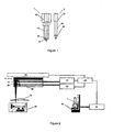
- FIG. 2 shows a laser match honing system for honing an injector body according to a preferred embodiment of the invention.
- the laser match honing system comprises a system controller 100 for reading data and controlling the operation of the laser match honing system.
- a measuring gauge 20 measures the dimensions of various inner portions of an injector body 1, in particular the inner diameter of the guiding hole 12.
- the measuring gauge 20 may be of any type known in the field, for example, a pneumatic gauge as used in the prior art.
- the measuring gauge 20 has a measuring table 30 on which an injector body 1 is supported to be moved reciprocately in a "Y" direction, which may be a vertical direction.
- Y a direction
- the dimensions of the injector body 1 are measured and the measured data are transmitted to the system controller 100 by the measuring gauge 20.
- the measured data comprise the dimensions of the guiding hole 12, the passage hole 14 and the needle seat 16 of the injector body 1, in particular the inner diameter of the guiding hole.
- the system controller 100 determines the corresponding desired dimensions of the guided portion 22, the stem portion 24 and the seating portion 26 of the injector needle 2, in particular the outer diameter of the guided portion 22, and the processing parameters to be applied onto the injector needle 2.
- An operator interface 90 for example a glass scale, may be connected to the system controller 100 for controlling the operation of the laser match honing system by means of the system controller.
- a laser beam source 40 and an optical measuring instrument 50 are coupled to the system controller 100 on one hand, and are coupled to a processing optic unit 60 on the other hand.
- the laser beam source 40 receives instructions from the system controller 100 and emits a laser beam towards the processing optic unit 60.
- the processing optic unit 60 comprises a set of processing optics 61 coupled to the laser beam source 40 and a set of measuring optics 62 coupled to the optical measuring instrument 50.
- the laser beam emitted from the laser beam source 40 is transmitted into the processing optic unit 60 and is reformed and reflected by the processing optics 61 so as to be output in a converged manner from the processing optic unit 60.
- the output converging laser beam is focused onto a focusing point on an outer surface of an injector needle 2 rotatably supported in a supporting device 80 for honing the outer surface of the injector needle 2, in particular that of the guided portion 22.
- the set of measuring optics 62 receives a measuring light from the optical measuring instrument 50 and directs the measuring light onto a point on the outer surface of the injector needle 2, in particular on that of the guided portion 22, which point coinciding with the focusing point of the laser beam.
- the measuring light is reflected back to the optical measuring instrument 50 via a reverse path.
- the real dimension or outer diameter of the injector needle 2 at this point can be calculated by the system controller 100.
- an ultrashort pulse laser is sent to this point within a time period as short as possible to form an ablation point by removing a piece of material of the injector needle.
- a lateral suction device 70 is provided between the processing optic unit 60 and the supporting device 80 near the honing location on the outer surface of the injector needle 2 for drawing away the material removed from the injector needle 2 to protect the optics of the processing optic unit 60 from the removed material.
- the injector needle 2 is automatically or manually loaded into the supporting device 80.
- the longitudinal central axis of the injector needle 2 lies preferably in a horizontal direction.
- the injector needle 2 is rotated while being honed by the laser beam.
- the honing location on the outer surface of the injector needle 2 is protected from being reachable from outside by a casing.
- the casing may for example shield the honing location by an angle of about 120° around the central axis of the injector needle.
- the supporting device 80 may hold the injector needle 2 by means of a clamp, such as a chuck, and drive the injector needle 2 to rotate around its central axis in a direction "R" shown in Figure 2 by means of the chuck or one or more friction rollers.
- a ceramic rolling bearing may also be used for supporting the injector needle.
- the processing optic unit 60 is movable in a direction "X" parallel to the central axis of the injector needle 2 which is in the supporting device 80.
- the direction "X" may be a horizontal direction, for example.
- a linear direct drive free of clearance may be used for driving the processing optic unit 60 to move.
- a femtosecond laser may be used as the ultrashort pulse laser for removing material from the injector needle. In this condition, no heat affected zone is found in the material near the ablation area.
- White light interferometry may be used in the optical measuring instrument 50.
- the wavelength of the honing laser and the wavelength of the measuring light of the optical measuring instrument 50 should be adapted to be compatible with each other or equal to each other, so that the laser beam and the measuring light are coaxially located between the processing optic unit 60 and the injector needle 2.
- the rotation speed of the injector needle 2 and the pulse frequency of the laser beam may be synchronized, but it is not necessarily so.
- the supporting device 80 comprises a high constant-velocity drive for the injector needle.
- the ablation points should be dense enough so as to form a fine grating.
- the quality of the grating of the ablation points mainly depends on the rotation speed, the geometry of the ablation points (craters) and the longitudinal focus feeding resolution of the laser beam.
- an injector needle is finely processed by laser honing, instead of grinding.
- a higher surface precision may be obtained.
- the same clamp is used during honing, which helps to improve the concentricity of the portions of the injector needle, as compared to the prior art where different clamps are used in different grinding steps.
- the laser ablation may be performed once after coating.
- the laser ablation may be performed twice, one before coating and the other after coating. If necessary, the laser ablation may be performed several times to the injector needle to meet the allocation requirement to the injector body.
- Laser ablation may be carried out in several operating modes so that laser ablation may be used primarily as a cutting process and then used as precise machining. For different operating modes, it is necessary to adjust the mean pulse power, the peak pulse power, the spacing of the grating of the ablation points, etc.
- a uni-axial scanner can be used as the processing optic unit.
- a bi-axial scanner is used so that, when a first injector needle is loaded, a second injector needle can be honed by laser.
- a tri-axial scanner in which a third axis is used for substituting an f- ⁇ lens for compensating the angle of laser radiation.
- the output power of the laser may be modulated for a local ablation suitable for a certain outer diameter of the injector needle. In this way, the necessary number of the pulses can be reduced and thus the manufacture cycle time can be shortened. Ideally, only a complete turn of the injector needle is necessary.
- laser ablation may be used for forming a desired feature or structure on the outer surface of the injector needle, for example, a feature for influencing a hydraulic flow rate, an opening for pressure progression, a feature for achieving a radial movement, etc.
- Figure 3 shows a laser match honing system for honing an injector body according to another preferred embodiment of the invention.
- the laser match honing system shown in Figure 3 is basically similar to that of Figure 2 , and thus only the differences between them are described below.
- the processing optic unit 60 is replaced by a scanner 110, and a joint optics 63 is arranged in the laser path between the laser beam source 40 and the scanner 110.
- the optical measuring instrument 50 is coupled between the joint optics 63 and the system controller 100. In this way, the path of the measuring light is combined into the laser path before they reach the common scanner 110.
- the scanner 110 is pivotable, so that the path of the laser and the measuring light between the scanner 110 and the supporting device 80 is movable in the direction "X".
- an injector body to be fitted with an injector needle is manufactured.
- the injector needle is lathed out from a bar material.
- the lathing process should remove as more material as possible.
- the injector needle, after lathing, is loaded into the supporting device 80 and held therein for rotation.
- the injector body is put onto the measuring table 30, and the dimensions of various matching portions of the injector body, in particular the inner diameter of the guiding hole 12, are measured by the measuring gauge 20.
- the measuring gauge 20 sends the measured data to the system controller 100 which determines the desired dimensions of the corresponding matching portions of the injector needle, in particular the outer diameter of the guided portion 22 of the injector needle.
- the system controller 100 operates the optical measuring instrument 50 to measure a real dimension of a corresponding matching portion of the injector needle, in particular the outer diameter of the guided portion. Then the system controller 100 compares the real dimension with the desired dimension. If the real dimension is larger than the desired dimension, then the system controller 100 commands the processing optic unit 60 or the scanner 110 to hone the matching portion of the injector needle by laser.
- optical measuring and laser honing are repeated until the desired dimension at a matching portion of the injector needle, in particular the desired outer diameter of the guided portion, is obtained.
- the grading step and the rough grinding step in the prior art are eliminated.
- the injector needles manufactured in this way can be allocated to the injector bodies having a particular manufacturing tolerance.
- the inventory of redundant injector needles is avoided.
- the invention results in a significant cost saving.
- the distance between the processing optic unit 60 and the injector needle is automatically measured during the operation of the system without any manual correction or adjustment. In this way, the whole system can be improved by eliminating the adjustment time, shortening the time for replacing worn parts and increasing the manufacture efficiency.
- the present invention is not limited to the processing of injector needles as described above. Rather, the invention may be applied to process any component of a pair of mechanically matching components.
Landscapes
- Engineering & Computer Science (AREA)
- Physics & Mathematics (AREA)
- Optics & Photonics (AREA)
- Mechanical Engineering (AREA)
- Plasma & Fusion (AREA)
- Fuel-Injection Apparatus (AREA)
- Laser Beam Processing (AREA)
- Finish Polishing, Edge Sharpening, And Grinding By Specific Grinding Devices (AREA)
- Length Measuring Devices By Optical Means (AREA)
Applications Claiming Priority (2)
| Application Number | Priority Date | Filing Date | Title |
|---|---|---|---|
| CN200910173534A CN102019504B (zh) | 2009-09-15 | 2009-09-15 | 激光适配珩磨系统和方法 |
| PCT/CN2010/076940 WO2011032495A1 (en) | 2009-09-15 | 2010-09-15 | Laser match honing system and method |
Publications (3)
| Publication Number | Publication Date |
|---|---|
| EP2477787A1 EP2477787A1 (en) | 2012-07-25 |
| EP2477787A4 EP2477787A4 (en) | 2013-07-17 |
| EP2477787B1 true EP2477787B1 (en) | 2014-11-12 |
Family
ID=43758112
Family Applications (1)
| Application Number | Title | Priority Date | Filing Date |
|---|---|---|---|
| EP10816699.2A Active EP2477787B1 (en) | 2009-09-15 | 2010-09-15 | Laser match honing system and method |
Country Status (7)
| Country | Link |
|---|---|
| US (1) | US8841575B2 (enExample) |
| EP (1) | EP2477787B1 (enExample) |
| JP (1) | JP5336664B2 (enExample) |
| CN (1) | CN102019504B (enExample) |
| BR (1) | BR112012005773B1 (enExample) |
| IN (1) | IN2012DN00276A (enExample) |
| WO (1) | WO2011032495A1 (enExample) |
Families Citing this family (2)
| Publication number | Priority date | Publication date | Assignee | Title |
|---|---|---|---|---|
| CN111113203A (zh) * | 2019-12-26 | 2020-05-08 | 苏州信能精密机械有限公司 | 一种阀套精密配珩的加工工艺 |
| CN116493760A (zh) * | 2023-04-24 | 2023-07-28 | 中国长江电力股份有限公司 | 运用于水电机组导通部件表面的激光珩磨装置及方法 |
Family Cites Families (17)
| Publication number | Priority date | Publication date | Assignee | Title |
|---|---|---|---|---|
| CH622204A5 (enExample) * | 1978-07-06 | 1981-03-31 | Sidco Sa | |
| US5112131A (en) * | 1981-02-27 | 1992-05-12 | Diffracto, Ltd. | Controlled machining of combustion chambers, gears and other surfaces |
| JPS6158951A (ja) | 1984-08-29 | 1986-03-26 | Daihatsu Motor Co Ltd | 内燃機関のシリンダブロック製造方法 |
| DE3932328A1 (de) * | 1989-09-28 | 1991-04-11 | Opel Adam Ag | Verfahren zur bearbeitung von durch reibung hochbeanspruchten flaechen in brennkraftmaschinen und vorrichtung zur durchfuehrung des verfahrens |
| JPH03146284A (ja) * | 1989-11-01 | 1991-06-21 | Ricoh Co Ltd | 動圧流体軸受の製造方法 |
| JPH0631469A (ja) * | 1992-06-19 | 1994-02-08 | Sony Corp | 動圧軸受用軸加工装置 |
| US5504303A (en) * | 1994-12-12 | 1996-04-02 | Saint-Gobain/Norton Industrial Ceramics Corp. | Laser finishing and measurement of diamond surface roughness |
| JP3728720B2 (ja) * | 2000-07-19 | 2005-12-21 | ミクロン精密株式会社 | エンジン用のピストンを研削する方法 |
| JP2002113641A (ja) * | 2000-10-10 | 2002-04-16 | Micron Seimitsu Kk | ニードルのマッチング研削方法、および同研削装置 |
| JP3721991B2 (ja) | 2001-01-29 | 2005-11-30 | 住友金属工業株式会社 | 渦電流式減速装置の制動力制御方法 |
| JP2002283196A (ja) * | 2001-03-26 | 2002-10-03 | Micron Seimitsu Kk | 適合研削方法および適合研削装置 |
| JP2004237399A (ja) * | 2003-02-06 | 2004-08-26 | Komatsu Ltd | 工作機械 |
| US7323657B2 (en) * | 2004-08-03 | 2008-01-29 | Matsushita Electric Industrial Co., Ltd. | Precision machining method using a near-field scanning optical microscope |
| DE202005011772U1 (de) * | 2005-04-07 | 2005-11-17 | Gehring Gmbh & Co. Kg | Laser-Honwerkzeug zum Erzeugen einer durch Mikrotaschen gebildeten Struktur auf einer tribologisch beanspruchten Fläche eines Werkstücks |
| DE202005005905U1 (de) * | 2005-04-07 | 2005-06-16 | Gehring Gmbh & Co. Kg | Vorrichtung zur Erzeugung von Vertiefungen in den zylindrischen Innenflächen von Bohrungen mit einem Laserstrahl |
| US20080000887A1 (en) * | 2006-06-28 | 2008-01-03 | Seagate Technology Llc | Method of laser honing |
| TW200936287A (en) * | 2007-11-26 | 2009-09-01 | Nat Inst Of Advanced Ind Scien | Mold removing method |
-
2009
- 2009-09-15 CN CN200910173534A patent/CN102019504B/zh active Active
-
2010
- 2010-09-15 US US13/496,295 patent/US8841575B2/en not_active Expired - Fee Related
- 2010-09-15 EP EP10816699.2A patent/EP2477787B1/en active Active
- 2010-09-15 WO PCT/CN2010/076940 patent/WO2011032495A1/en not_active Ceased
- 2010-09-15 IN IN276DEN2012 patent/IN2012DN00276A/en unknown
- 2010-09-15 BR BR112012005773-1A patent/BR112012005773B1/pt not_active IP Right Cessation
- 2010-09-15 JP JP2012529113A patent/JP5336664B2/ja not_active Expired - Fee Related
Also Published As
| Publication number | Publication date |
|---|---|
| EP2477787A4 (en) | 2013-07-17 |
| BR112012005773A2 (pt) | 2017-05-30 |
| BR112012005773B1 (pt) | 2020-12-01 |
| CN102019504B (zh) | 2012-08-29 |
| US8841575B2 (en) | 2014-09-23 |
| US20120273471A1 (en) | 2012-11-01 |
| EP2477787A1 (en) | 2012-07-25 |
| JP5336664B2 (ja) | 2013-11-06 |
| WO2011032495A1 (en) | 2011-03-24 |
| IN2012DN00276A (enExample) | 2015-05-08 |
| CN102019504A (zh) | 2011-04-20 |
| JP2013504435A (ja) | 2013-02-07 |
Similar Documents
| Publication | Publication Date | Title |
|---|---|---|
| CN102189335B (zh) | 用于制造旋转对称工具的激光加工装置和方法 | |
| EP2923791B1 (en) | Laser machining method | |
| CN103260813B (zh) | 包括用于光聚焦的单透镜的激光束机械加工装置和激光机械加工的方法 | |
| US10549382B2 (en) | Laser-assisted micromachining systems and methods | |
| US8674259B2 (en) | Manufacturing system for producing reverse-tapered orifice | |
| US8237081B2 (en) | Manufacturing system having delivery media and GRIN lens | |
| EP3072629A1 (en) | Laser processing apparatus and laser processing method | |
| KR20170122254A (ko) | 레이저 가공을 위한 초기 거리 접근 방법 | |
| EP1772526B1 (en) | Device for improving residual stress of piping | |
| EP2477787B1 (en) | Laser match honing system and method | |
| US20240261867A1 (en) | Machine tool for machining a micromechanical component, and machining method implemented by said machine tool | |
| CN112824004A (zh) | 一种复合型水助激光加工系统及其加工方法 | |
| EP4380737B1 (en) | Apparatus and process for surface processing of cylindrical bodies, in particular rolling cylinders | |
| US20090294416A1 (en) | Laser manufacturing system having real-time feedback | |
| CN102233483B (zh) | 用于加工喷嘴本体的设备和方法 | |
| CN210435558U (zh) | 一种飞秒激光加工锥度可控的打孔装置 | |
| JP2022536957A (ja) | レーザ走査ヘッドによって方向づけられたレーザビームおよび横方向粉末射出によって加工物の定められた表面に材料を付加するシステムおよび方法 | |
| JP7303587B2 (ja) | 切削装置 | |
| US20210299810A1 (en) | Cutting edge machining apparatus and cutting apparatus | |
| TWM483137U (zh) | 透鏡加工裝置 | |
| CN114703437A (zh) | 金属部件飞秒激光抗磨损抗疲劳一体化强化方法与装置 | |
| EP3577336B1 (en) | Method for achieving final air gap and parallelism of a fuel injector control valve | |
| JP2017001068A (ja) | レーザー溶接装置および接合体を生産する方法 | |
| CN105873725A (zh) | 用于借助磨削来测量和产生工件外部额定轮廓的方法和磨削机 | |
| JP7144101B2 (ja) | 切削装置 |
Legal Events
| Date | Code | Title | Description |
|---|---|---|---|
| PUAI | Public reference made under article 153(3) epc to a published international application that has entered the european phase |
Free format text: ORIGINAL CODE: 0009012 |
|
| 17P | Request for examination filed |
Effective date: 20120416 |
|
| AK | Designated contracting states |
Kind code of ref document: A1 Designated state(s): AL AT BE BG CH CY CZ DE DK EE ES FI FR GB GR HR HU IE IS IT LI LT LU LV MC MK MT NL NO PL PT RO SE SI SK SM TR |
|
| DAX | Request for extension of the european patent (deleted) | ||
| A4 | Supplementary search report drawn up and despatched |
Effective date: 20130619 |
|
| RIC1 | Information provided on ipc code assigned before grant |
Ipc: B24B 33/00 20060101ALI20130613BHEP Ipc: B23K 26/36 20060101ALI20130613BHEP Ipc: B23K 26/00 20060101ALI20130613BHEP Ipc: B24B 5/14 20060101AFI20130613BHEP |
|
| GRAP | Despatch of communication of intention to grant a patent |
Free format text: ORIGINAL CODE: EPIDOSNIGR1 |
|
| GRAJ | Information related to disapproval of communication of intention to grant by the applicant or resumption of examination proceedings by the epo deleted |
Free format text: ORIGINAL CODE: EPIDOSDIGR1 |
|
| GRAP | Despatch of communication of intention to grant a patent |
Free format text: ORIGINAL CODE: EPIDOSNIGR1 |
|
| INTG | Intention to grant announced |
Effective date: 20140506 |
|
| INTG | Intention to grant announced |
Effective date: 20140602 |
|
| GRAS | Grant fee paid |
Free format text: ORIGINAL CODE: EPIDOSNIGR3 |
|
| GRAA | (expected) grant |
Free format text: ORIGINAL CODE: 0009210 |
|
| AK | Designated contracting states |
Kind code of ref document: B1 Designated state(s): AL AT BE BG CH CY CZ DE DK EE ES FI FR GB GR HR HU IE IS IT LI LT LU LV MC MK MT NL NO PL PT RO SE SI SK SM TR |
|
| REG | Reference to a national code |
Ref country code: GB Ref legal event code: FG4D |
|
| REG | Reference to a national code |
Ref country code: CH Ref legal event code: EP |
|
| REG | Reference to a national code |
Ref country code: AT Ref legal event code: REF Ref document number: 695439 Country of ref document: AT Kind code of ref document: T Effective date: 20141115 |
|
| REG | Reference to a national code |
Ref country code: IE Ref legal event code: FG4D |
|
| REG | Reference to a national code |
Ref country code: DE Ref legal event code: R096 Ref document number: 602010020258 Country of ref document: DE Effective date: 20141224 |
|
| REG | Reference to a national code |
Ref country code: NL Ref legal event code: VDEP Effective date: 20141112 |
|
| REG | Reference to a national code |
Ref country code: AT Ref legal event code: MK05 Ref document number: 695439 Country of ref document: AT Kind code of ref document: T Effective date: 20141112 |
|
| PG25 | Lapsed in a contracting state [announced via postgrant information from national office to epo] |
Ref country code: IS Free format text: LAPSE BECAUSE OF FAILURE TO SUBMIT A TRANSLATION OF THE DESCRIPTION OR TO PAY THE FEE WITHIN THE PRESCRIBED TIME-LIMIT Effective date: 20150312 Ref country code: PT Free format text: LAPSE BECAUSE OF FAILURE TO SUBMIT A TRANSLATION OF THE DESCRIPTION OR TO PAY THE FEE WITHIN THE PRESCRIBED TIME-LIMIT Effective date: 20150312 Ref country code: LT Free format text: LAPSE BECAUSE OF FAILURE TO SUBMIT A TRANSLATION OF THE DESCRIPTION OR TO PAY THE FEE WITHIN THE PRESCRIBED TIME-LIMIT Effective date: 20141112 Ref country code: NO Free format text: LAPSE BECAUSE OF FAILURE TO SUBMIT A TRANSLATION OF THE DESCRIPTION OR TO PAY THE FEE WITHIN THE PRESCRIBED TIME-LIMIT Effective date: 20150212 Ref country code: ES Free format text: LAPSE BECAUSE OF FAILURE TO SUBMIT A TRANSLATION OF THE DESCRIPTION OR TO PAY THE FEE WITHIN THE PRESCRIBED TIME-LIMIT Effective date: 20141112 Ref country code: FI Free format text: LAPSE BECAUSE OF FAILURE TO SUBMIT A TRANSLATION OF THE DESCRIPTION OR TO PAY THE FEE WITHIN THE PRESCRIBED TIME-LIMIT Effective date: 20141112 Ref country code: NL Free format text: LAPSE BECAUSE OF FAILURE TO SUBMIT A TRANSLATION OF THE DESCRIPTION OR TO PAY THE FEE WITHIN THE PRESCRIBED TIME-LIMIT Effective date: 20141112 |
|
| PG25 | Lapsed in a contracting state [announced via postgrant information from national office to epo] |
Ref country code: SE Free format text: LAPSE BECAUSE OF FAILURE TO SUBMIT A TRANSLATION OF THE DESCRIPTION OR TO PAY THE FEE WITHIN THE PRESCRIBED TIME-LIMIT Effective date: 20141112 Ref country code: GR Free format text: LAPSE BECAUSE OF FAILURE TO SUBMIT A TRANSLATION OF THE DESCRIPTION OR TO PAY THE FEE WITHIN THE PRESCRIBED TIME-LIMIT Effective date: 20150213 Ref country code: PL Free format text: LAPSE BECAUSE OF FAILURE TO SUBMIT A TRANSLATION OF THE DESCRIPTION OR TO PAY THE FEE WITHIN THE PRESCRIBED TIME-LIMIT Effective date: 20141112 Ref country code: LV Free format text: LAPSE BECAUSE OF FAILURE TO SUBMIT A TRANSLATION OF THE DESCRIPTION OR TO PAY THE FEE WITHIN THE PRESCRIBED TIME-LIMIT Effective date: 20141112 Ref country code: AT Free format text: LAPSE BECAUSE OF FAILURE TO SUBMIT A TRANSLATION OF THE DESCRIPTION OR TO PAY THE FEE WITHIN THE PRESCRIBED TIME-LIMIT Effective date: 20141112 Ref country code: HR Free format text: LAPSE BECAUSE OF FAILURE TO SUBMIT A TRANSLATION OF THE DESCRIPTION OR TO PAY THE FEE WITHIN THE PRESCRIBED TIME-LIMIT Effective date: 20141112 Ref country code: CY Free format text: LAPSE BECAUSE OF FAILURE TO SUBMIT A TRANSLATION OF THE DESCRIPTION OR TO PAY THE FEE WITHIN THE PRESCRIBED TIME-LIMIT Effective date: 20141112 |
|
| PG25 | Lapsed in a contracting state [announced via postgrant information from national office to epo] |
Ref country code: SK Free format text: LAPSE BECAUSE OF FAILURE TO SUBMIT A TRANSLATION OF THE DESCRIPTION OR TO PAY THE FEE WITHIN THE PRESCRIBED TIME-LIMIT Effective date: 20141112 Ref country code: RO Free format text: LAPSE BECAUSE OF FAILURE TO SUBMIT A TRANSLATION OF THE DESCRIPTION OR TO PAY THE FEE WITHIN THE PRESCRIBED TIME-LIMIT Effective date: 20141112 Ref country code: EE Free format text: LAPSE BECAUSE OF FAILURE TO SUBMIT A TRANSLATION OF THE DESCRIPTION OR TO PAY THE FEE WITHIN THE PRESCRIBED TIME-LIMIT Effective date: 20141112 Ref country code: DK Free format text: LAPSE BECAUSE OF FAILURE TO SUBMIT A TRANSLATION OF THE DESCRIPTION OR TO PAY THE FEE WITHIN THE PRESCRIBED TIME-LIMIT Effective date: 20141112 |
|
| REG | Reference to a national code |
Ref country code: DE Ref legal event code: R097 Ref document number: 602010020258 Country of ref document: DE |
|
| PLBE | No opposition filed within time limit |
Free format text: ORIGINAL CODE: 0009261 |
|
| STAA | Information on the status of an ep patent application or granted ep patent |
Free format text: STATUS: NO OPPOSITION FILED WITHIN TIME LIMIT |
|
| 26N | No opposition filed |
Effective date: 20150813 |
|
| PG25 | Lapsed in a contracting state [announced via postgrant information from national office to epo] |
Ref country code: SI Free format text: LAPSE BECAUSE OF FAILURE TO SUBMIT A TRANSLATION OF THE DESCRIPTION OR TO PAY THE FEE WITHIN THE PRESCRIBED TIME-LIMIT Effective date: 20141112 |
|
| PG25 | Lapsed in a contracting state [announced via postgrant information from national office to epo] |
Ref country code: LU Free format text: LAPSE BECAUSE OF FAILURE TO SUBMIT A TRANSLATION OF THE DESCRIPTION OR TO PAY THE FEE WITHIN THE PRESCRIBED TIME-LIMIT Effective date: 20150915 Ref country code: MC Free format text: LAPSE BECAUSE OF FAILURE TO SUBMIT A TRANSLATION OF THE DESCRIPTION OR TO PAY THE FEE WITHIN THE PRESCRIBED TIME-LIMIT Effective date: 20141112 |
|
| REG | Reference to a national code |
Ref country code: CH Ref legal event code: PL |
|
| GBPC | Gb: european patent ceased through non-payment of renewal fee |
Effective date: 20150915 |
|
| REG | Reference to a national code |
Ref country code: IE Ref legal event code: MM4A |
|
| PG25 | Lapsed in a contracting state [announced via postgrant information from national office to epo] |
Ref country code: IE Free format text: LAPSE BECAUSE OF NON-PAYMENT OF DUE FEES Effective date: 20150915 Ref country code: LI Free format text: LAPSE BECAUSE OF NON-PAYMENT OF DUE FEES Effective date: 20150930 Ref country code: CH Free format text: LAPSE BECAUSE OF NON-PAYMENT OF DUE FEES Effective date: 20150930 Ref country code: GB Free format text: LAPSE BECAUSE OF NON-PAYMENT OF DUE FEES Effective date: 20150915 |
|
| REG | Reference to a national code |
Ref country code: FR Ref legal event code: PLFP Year of fee payment: 7 |
|
| PG25 | Lapsed in a contracting state [announced via postgrant information from national office to epo] |
Ref country code: MT Free format text: LAPSE BECAUSE OF FAILURE TO SUBMIT A TRANSLATION OF THE DESCRIPTION OR TO PAY THE FEE WITHIN THE PRESCRIBED TIME-LIMIT Effective date: 20141112 |
|
| PG25 | Lapsed in a contracting state [announced via postgrant information from national office to epo] |
Ref country code: BG Free format text: LAPSE BECAUSE OF FAILURE TO SUBMIT A TRANSLATION OF THE DESCRIPTION OR TO PAY THE FEE WITHIN THE PRESCRIBED TIME-LIMIT Effective date: 20141112 Ref country code: HU Free format text: LAPSE BECAUSE OF FAILURE TO SUBMIT A TRANSLATION OF THE DESCRIPTION OR TO PAY THE FEE WITHIN THE PRESCRIBED TIME-LIMIT; INVALID AB INITIO Effective date: 20100915 Ref country code: SM Free format text: LAPSE BECAUSE OF FAILURE TO SUBMIT A TRANSLATION OF THE DESCRIPTION OR TO PAY THE FEE WITHIN THE PRESCRIBED TIME-LIMIT Effective date: 20141112 |
|
| REG | Reference to a national code |
Ref country code: FR Ref legal event code: PLFP Year of fee payment: 8 |
|
| PG25 | Lapsed in a contracting state [announced via postgrant information from national office to epo] |
Ref country code: BE Free format text: LAPSE BECAUSE OF FAILURE TO SUBMIT A TRANSLATION OF THE DESCRIPTION OR TO PAY THE FEE WITHIN THE PRESCRIBED TIME-LIMIT Effective date: 20141112 |
|
| PG25 | Lapsed in a contracting state [announced via postgrant information from national office to epo] |
Ref country code: MK Free format text: LAPSE BECAUSE OF FAILURE TO SUBMIT A TRANSLATION OF THE DESCRIPTION OR TO PAY THE FEE WITHIN THE PRESCRIBED TIME-LIMIT Effective date: 20141112 |
|
| REG | Reference to a national code |
Ref country code: FR Ref legal event code: PLFP Year of fee payment: 9 |
|
| PG25 | Lapsed in a contracting state [announced via postgrant information from national office to epo] |
Ref country code: AL Free format text: LAPSE BECAUSE OF FAILURE TO SUBMIT A TRANSLATION OF THE DESCRIPTION OR TO PAY THE FEE WITHIN THE PRESCRIBED TIME-LIMIT Effective date: 20141112 |
|
| PGFP | Annual fee paid to national office [announced via postgrant information from national office to epo] |
Ref country code: FR Payment date: 20200922 Year of fee payment: 11 Ref country code: TR Payment date: 20200914 Year of fee payment: 11 Ref country code: CZ Payment date: 20200907 Year of fee payment: 11 |
|
| PGFP | Annual fee paid to national office [announced via postgrant information from national office to epo] |
Ref country code: IT Payment date: 20200930 Year of fee payment: 11 |
|
| PG25 | Lapsed in a contracting state [announced via postgrant information from national office to epo] |
Ref country code: CZ Free format text: LAPSE BECAUSE OF NON-PAYMENT OF DUE FEES Effective date: 20210915 |
|
| PG25 | Lapsed in a contracting state [announced via postgrant information from national office to epo] |
Ref country code: FR Free format text: LAPSE BECAUSE OF NON-PAYMENT OF DUE FEES Effective date: 20210930 |
|
| PG25 | Lapsed in a contracting state [announced via postgrant information from national office to epo] |
Ref country code: IT Free format text: LAPSE BECAUSE OF NON-PAYMENT OF DUE FEES Effective date: 20210915 |
|
| PGFP | Annual fee paid to national office [announced via postgrant information from national office to epo] |
Ref country code: DE Payment date: 20221125 Year of fee payment: 13 |
|
| REG | Reference to a national code |
Ref country code: DE Ref legal event code: R119 Ref document number: 602010020258 Country of ref document: DE |
|
| PG25 | Lapsed in a contracting state [announced via postgrant information from national office to epo] |
Ref country code: DE Free format text: LAPSE BECAUSE OF NON-PAYMENT OF DUE FEES Effective date: 20240403 |