EP2477458A1 - Appareil d'éclairage et dispositif de diode électroluminescente - Google Patents
Appareil d'éclairage et dispositif de diode électroluminescente Download PDFInfo
- Publication number
- EP2477458A1 EP2477458A1 EP12150792A EP12150792A EP2477458A1 EP 2477458 A1 EP2477458 A1 EP 2477458A1 EP 12150792 A EP12150792 A EP 12150792A EP 12150792 A EP12150792 A EP 12150792A EP 2477458 A1 EP2477458 A1 EP 2477458A1
- Authority
- EP
- European Patent Office
- Prior art keywords
- led
- impedance
- drive current
- providing component
- providing
- Prior art date
- Legal status (The legal status is an assumption and is not a legal conclusion. Google has not performed a legal analysis and makes no representation as to the accuracy of the status listed.)
- Withdrawn
Links
- 239000004065 semiconductor Substances 0.000 claims description 8
- 238000010586 diagram Methods 0.000 description 6
- 230000007423 decrease Effects 0.000 description 4
- 238000000034 method Methods 0.000 description 4
- 230000015556 catabolic process Effects 0.000 description 3
- 238000006731 degradation reaction Methods 0.000 description 3
- 101100500421 Chlamydomonas reinhardtii DHC1 gene Proteins 0.000 description 2
- 101100500422 Chlamydomonas reinhardtii DHC10 gene Proteins 0.000 description 2
- OAICVXFJPJFONN-UHFFFAOYSA-N Phosphorus Chemical compound [P] OAICVXFJPJFONN-UHFFFAOYSA-N 0.000 description 2
- 238000004519 manufacturing process Methods 0.000 description 2
- 239000003086 colorant Substances 0.000 description 1
- 230000008878 coupling Effects 0.000 description 1
- 238000010168 coupling process Methods 0.000 description 1
- 238000005859 coupling reaction Methods 0.000 description 1
- 230000001419 dependent effect Effects 0.000 description 1
- 238000005516 engineering process Methods 0.000 description 1
- 230000007613 environmental effect Effects 0.000 description 1
- 238000005286 illumination Methods 0.000 description 1
- 230000001771 impaired effect Effects 0.000 description 1
Images


Classifications
-
- H—ELECTRICITY
- H05—ELECTRIC TECHNIQUES NOT OTHERWISE PROVIDED FOR
- H05B—ELECTRIC HEATING; ELECTRIC LIGHT SOURCES NOT OTHERWISE PROVIDED FOR; CIRCUIT ARRANGEMENTS FOR ELECTRIC LIGHT SOURCES, IN GENERAL
- H05B45/00—Circuit arrangements for operating light-emitting diodes [LED]
- H05B45/20—Controlling the colour of the light
-
- H—ELECTRICITY
- H05—ELECTRIC TECHNIQUES NOT OTHERWISE PROVIDED FOR
- H05B—ELECTRIC HEATING; ELECTRIC LIGHT SOURCES NOT OTHERWISE PROVIDED FOR; CIRCUIT ARRANGEMENTS FOR ELECTRIC LIGHT SOURCES, IN GENERAL
- H05B45/00—Circuit arrangements for operating light-emitting diodes [LED]
- H05B45/40—Details of LED load circuits
- H05B45/44—Details of LED load circuits with an active control inside an LED matrix
- H05B45/48—Details of LED load circuits with an active control inside an LED matrix having LEDs organised in strings and incorporating parallel shunting devices
Definitions
- the present invention relates to a lighting apparatus and the structure of a light emitting diode (LED) device thereof and, more particularly, to an LED device with reduced attenuation in brightness (luminous decay, light decay, light attenuation, light decline or light degradation) and a technique that reduces attenuation in brightness in red LED caused by an increase in temperature.
- LED light emitting diode
- the present invention provides an LED device that is capable of effectively reducing the attenuation in brightness in a string of red LEDs thereof caused by an increase in temperature.
- the present invention further provides a lighting apparatus that is capable of effectively reducing the attenuation in brightness in a string of red LEDs thereof caused by an increase in temperature.
- the lighting apparatus can emit light under high ambient temperature such that the emitted light still satisfies the requirement of the 7-step macadam and, optimally, the requirement of the 4-step macadam.
- an LED device may comprise a first LED, at least one impedance-providing component, and a driver.
- the first LED may have an internal impedance and may be configured to emit light of a first wavelength.
- the at least one impedance-providing component may be coupled in parallel with the first LED, and may provide a shunt impedance having a value that varies in positive proportion with a variation in an ambient temperature.
- the driver may be respectively coupled in series with the first LED and the at least one impedance-providing component. The driver may provide a drive current divided to flow through the first LED and the at least one impedance-providing component according to the shunt impedance and the internal impedance.
- the drive current is divided into a first partial drive current that flows through the first LED and a second partial drive current that flows through the at least one impedance-providing component.
- a ratio between a value of the first partial drive current and a value of the second partial drive current may be proportional to a ratio between a value of the shunt impedance provided by the at least one impedance-providing component and a value of the internal impedance of the first LED.
- the at least one impedance-providing component may comprise a plurality of impedance-providing components each of which providing a respective shunt impedance having a respective value that varies in positive proportion with the variation in the ambient temperature.
- the at least one impedance-providing component may comprise a semiconductor component, a thermistor, a transistor, or a diode having a positive temperature coefficient.
- the LED device may further comprise a second LED that is respectively coupled in series with the driver, the first LED, and the at least one impedance-providing component.
- the second LED may be configured to emit light of a second wavelength.
- the second LED, the first LED, and the driver may be coupled in series such that the second LED is coupled between the driver and the first LED or the first LED is coupled between the driver and the second LED.
- the second LED may comprise a blue LED, a green LED, a yellow LED, an orange LED, an ultraviolet LED, a near blue LED, a white LED, or a combination thereof.
- an LED device may comprise a first LED, at least one impedance-providing component, a string of one or more second LEDs, and a driver.
- the first LED may have an internal impedance and may be configured to emit light of a first wavelength.
- the at least one impedance-providing component may be coupled in parallel with the first LED and provide a shunt impedance having a value that varies in positive proportion with a variation in an ambient temperature.
- the string of one or more second LEDs may be respectively coupled in series with the first LED and the at least one impedance-providing component. Each of the one or more second LEDs may be configured to emit light of a respective wavelength that is less than the first wavelength.
- the driver may be respectively coupled in series with the first LED, the string of one or more second LEDs, and the at least one impedance-providing component.
- the driver may provide a drive current to the string of one or more second LEDs.
- the drive current is divided to flow through the first LED and the at least one impedance-providing component according to the shunt impedance and the internal impedance.
- the drive current is divided into a first partial drive current that flows through the first LED and a second partial drive current that flows through the at least one impedance-providing component.
- a ratio between a value of the first partial drive current and a value of the second partial drive current may be proportional to a ratio between a value of the shunt impedance provided by the at least one impedance-providing component and a value of the internal impedance of the first LED.
- the at least one impedance-providing component may comprise a plurality of impedance-providing components each providing a respective shunt impedance having a respective value that varies in positive proportion with the variation in the ambient temperature.
- the at least one impedance-providing component may comprise a semiconductor component, a thermistor, a transistor, or a diode having a positive temperature coefficient.
- the first LED may comprise a red LED
- the string of one or more second LEDs may comprise a blue LED, a green LED, a yellow LED, an orange LED, an ultraviolet LED, a near blue LED, a white LED, or a combination thereof.
- the LED device may further comprise a string of one or more third LEDs that is respectively coupled in series with the driver, the first LED, the string of one or more second LEDs, and the at least one impedance-providing component.
- Each of the one or more third LEDs may be configured to emit light of a respective wavelength that is less than the first wavelength.
- the string of one or more third LEDs may be coupled in series and between the driver and the first LED.
- the first LED may comprise a red LED
- the string of one or more third LEDs may comprise a blue LED, a green LED, a yellow LED, an orange LED, an ultraviolet LED, a near blue LED, a white LED, or a combination thereof.
- a lighting apparatus comprising a first LED, at least one impedance-providing component, a second LED and a driver.
- the first LED has an internal impedance and a first light decay.
- the at least one impedance-providing component is coupled in parallel with the first LED.
- the at least one impedance-providing component provides a shunt impedance having a value that varies in positive proportion with a variation in an ambient temperature.
- the second LED is respectively coupled in series with the first LED and the at least one impedance-providing component.
- the second LED has a second decay.
- the first light decay is more severe than the second light decay.
- the driver is respectively coupled in series with the first LED, the second LED and the at least one impedance-providing component.
- the driver provides a drive current to the second LED.
- the drive current is divided to flow through the first LED and the at least one impedance-providing component according to the shunt impedance and the internal imped
- the at least one impedance-providing component comprises a semiconductor component, a thermistor, a transistor, or a diode having a positive temperature coefficient.
- a third LED is respectively coupled in series with the first LED, the second LED, the at least one impedance-providing component and the driver.
- the third LED has a third light decay.
- the first light decay is more severe than the third light decay.
- the third LED is coupled in series and between the driver and the first LED.
- the first LED comprises a red LED.
- the second LED comprises a blue LED, a green LED, a yellow LED, an orange LED, an ultraviolet LED, a near blue LED, a white LED, or a combination thereof.
- the third LED comprises a blue LED, a green LED, a yellow LED, an orange LED, an ultraviolet LED, a near blue LED, a white LED, or a combination thereof.
- the drive current is divided into a first partial drive current that flows through the first LED and a second partial drive current that flows through the at least one impedance-providing component.
- a ratio between a value of the first partial drive current and a value of the second partial drive current is proportional to a ratio between a value of the shunt impedance provided by the at least one impedance-providing component and a value of the internal impedance of the first LED.
- a lighting apparatus may comprise an LED device.
- the LED device may include a first LED, at least one impedance-providing component, and a driver.
- the first LED may have an internal impedance and may be configured to emit light of a first wavelength.
- the at least one impedance-providing component may be coupled in parallel with the first LED and may provide a shunt impedance having a value that varies in positive proportion with a variation in an ambient temperature.
- the driver may be respectively coupled in series with the first LED, and the at least one impedance-providing component.
- the driver may provide a drive current that is divided into a first partial drive current that flows through the first LED and a second partial drive current that flows through the at least one impedance-providing component.
- a ratio between a value of the first partial drive current and a value of the second partial drive current may be proportional to a ratio between a value of the shunt impedance provided by the at least one impedance-providing component and a value of the internal impedance of the first LED.
- the at least one impedance-providing component may comprise a semiconductor component, a thermistor, a transistor, or a diode having a positive temperature coefficient.
- the lighting apparatus may further comprise a string of one or more second LEDs that is respectively coupled in series with the first LED and the driver. Each of the one or more second LEDs may be configured to emit light of a respective wavelength that is less than the first wavelength.
- the lighting apparatus may additionally comprise a string of one or more third LEDs that is respectively coupled in series with the driver, the first LED, and the string of one or more second LEDs. Each of the one or more third LEDs may be configured to emit light of a respective wavelength that is less than the first wavelength.
- the string of one or more third LEDs may be coupled in series and between the driver and the first LED.
- the first LED may comprise a red LED.
- the string of one or more second LEDs may comprise a blue LED, a green LED, a yellow LED, an orange LED, an ultraviolet LED, a near blue LED, a white LED, or a combination thereof.
- the string of one or more third LEDs may comprise a blue LED, a green LED, a yellow LED, an orange LED, an ultraviolet LED, a near blue LED, a white LED, or a combination thereof.
- each of the at least one first LED may be coupled in parallel with a respective one of the at least one impedance-providing component.
- the lighting apparatus may further comprise a plurality of strings of one or more second LEDs. Each string of one or more second LEDs may be respectively coupled in series with a respective one of the at least one first LED and the driver. Each LED of each string of one or more second LEDs may be configured to emit light of a respective wavelength that is less than the first wavelength.
- FIG. 1 is a block diagram of an LED device in accordance with an embodiment of the present invention.
- FIG. 2A is a block diagram of an LED device in accordance with another embodiment of the present invention.
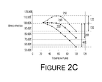
- Figures 2B and 2C are diagrams showing a relationship between the lighting efficiency and relative brightness of an LED device and the ambient temperature.
- Figure 3A is a block diagram of an LED device in accordance with yet another embodiment of the present invention.
- Figure 3B is a block diagram of an LED device in accordance with still another embodiment of the present invention.
- FIG. 4 is a block diagram of a lighting apparatus in accordance with an embodiment of the present invention.
- FIG. 1 illustrates an LED device 100 in accordance with an embodiment of the present invention.
- the LED device 100 includes a driver 110, a string of one or more red LEDs 120, and an impedance-providing component 130.
- the driver 110 provides a drive current ID.
- the driver 110 may include a current generator that utilizes a voltage-controlled current source or an independent current source to provide the drive current ID, which is stable. As current generating devices capable of providing a stable drive current are well known in the art, in the interest of brevity detailed description of the driver 110 will not be provided.
- the string of one or more red LEDs 120 includes a quantity of N of LEDs 121 coupled in series, where N is a positive integer.
- Figure 1 illustrates one exemplary implementation, and N is equal to 1 in Figure 1 .
- the N LEDs are coupled in the same direction (e.g., positively biased with respect to the driver 110) and in series.
- the impedance-providing component 130 is coupled in parallel with the string of one or more red LEDs 120.
- the impedance-providing component 130 provides a shunt impedance RD the value of which depends on the ambient temperature surrounding the impedance-providing component 130. That is, according to Kirchhoff's current laws, the drive current ID provided by the driver 110 is divided into a first partial drive current ID1 and a second partial drive current ID2.
- the first partial drive current ID1 and the second partial drive current ID2 flow through the string of one or more red LEDs 120 and the impedance-providing component 130, respectively.
- the value of the drive current ID is equal to the sum of the value of the first partial drive current ID1 and the value of the second partial drive current ID2. More specifically, a voltage drop across the string of one or more red LEDs 120 is the same as a voltage drop across the impedance-providing component 130.
- a ratio between the value of the first partial drive current ID1 and the value of the second partial drive current ID2 is proportional to a ratio between a value of the shunt impedance RD provided by the impedance-providing component 130 and a value of an internal impedance of the string of one or more red LEDs 120.
- the value of the shunt impedance RD provided by the impedance-providing component 130 varies in positive proportion with a variation in the ambient temperature. For example, when the ambient temperature increases, the shunt impedance RD increases proportionally.
- the value of the shunt impedance RD provided by the impedance-providing component 130 is greater than the value of the internal impedance of the string of one or more red LEDs 120, the value of the first partial drive current ID1 is greater than the value of the second partial drive current ID2. Conversely, when the value of the shunt impedance RD provided by the impedance-providing component 130 is less than the value of the internal impedance of the string of one or more red LEDs 120, the value of the first partial drive current ID1 is less than the value of the second partial drive current ID2.
- the drive current ID is equally divided between the first partial drive current ID1 and the second partial drive current ID2.
- the value of the shunt impedance RD provided by the impedance-providing component 130 increases corresponding to an increase in the ambient temperature over time.
- the value of the shunt impedance RD increases, the value of the first partial drive current ID1 that flows through the string of one or more red LEDs 120 also increases.
- the increase in the first partial drive current ID1 due to an increase in the ambient temperature effectively compensates for a decrease, or attenuation, in the brightness of the string of one or more red LEDs 120 that would result due to an increase in the ambient temperature had there been no such compensation.
- the value of the shunt impedance RD provided by the impedance-providing component 130 is selected based on the temperature-dependent attenuation in brightness of the string of one or more red LEDs 120 and a relationship between the brightness of the string of one or more red LEDs 120 and the drive current ID.
- the impedance-providing component 130 may comprise a thermistor with a positive temperature coefficient.
- the impedance-providing component 130 may be a semiconductor component having a positive temperature coefficient, e.g., a transistor or a diode with a positive temperature coefficient, fabricated during the chip fabrication process.
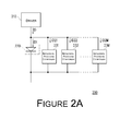
- FIG. 2A illustrates an LED device 200 in accordance with another embodiment of the present invention.
- the LED device 200 includes a driver 210, a string of one or more red LEDs 220, and a plurality of impedance-providing components 231-23M.
- the LED device 200 includes a quantity of M of impedance-providing components 231-23M, where M is a positive integer.
- M is a positive integer.
- Each of the impedance-providing components 231-23M is coupled in parallel with the string of one or more red LEDs 220.
- the plurality of impedance-providing components 231-23M provide a plurality of shunt impedance each having a respective value that varies in positive proportion with a variation in the ambient temperature.
- the string of one or more red LEDs 220 includes three LEDs coupled in series.
- the driver 210 provides a drive current ID that is divided into a plurality of partial drive currents ID1, ID21-ID2M.
- the values of the partial drive currents ID1, ID21-ID2M depend on the values of the shunt impedance of the plurality of impedance-providing components 231-23M and a value of the internal impedance of the string of one or more red LEDs 220. More specifically, the partial drive current ID1 flows through the string of one or more red LEDs 220 to cause the string of one or more red LEDs 220 to emit light. Additionally, a voltage drop across the string of one or more red LEDs 220 is the same as a respective voltage drop across each of the plurality of the impedance-providing components 231-23M.
- Figures 2B and 2C illustrate a relationship between the lighting efficiency and relative brightness of an LED device and the ambient temperature, respectively.
- a curve 210 shows a relationship between the lighting efficiency of a conventional LED device and the ambient temperature, where the conventional LED device includes a string of one or more red LEDs having two LEDs coupled in series without any impedance-providing component.
- a curve 220 shows a relationship between the lighting efficiency of a proposed LED device and the ambient temperature, where the proposed LED device includes a string of one or more red LEDs having two LEDs coupled in series and one or more impedance-providing components coupled in parallel with the string of one or more red LEDs.
- the string of one or more red LEDs of the conventional LED device indicated by the curve 210 suffers a large attenuation in brightness when the ambient temperature is greater than 50°C.
- the string of one or more red LEDs of the proposed LED device indicated by the curve 220 does not suffer a noticeable attenuation in brightness until the ambient temperature is greater than 60°C.
- a curve 230 shows a relationship between the relative brightness of lighting of a conventional LED device and the ambient temperature, where the conventional LED device includes a string of one or more red LEDs having two LEDs coupled in series without any impedance-providing component.
- a curve 240 shows a relationship between the relative brightness of lighting of a proposed LED device and the ambient temperature, where the proposed LED device includes a string of two red LEDs coupled in series and two impedance-providing components that are coupled in parallel with each other and in parallel with the string of two red LEDs.
- a curve 250 shows a relationship between the relative brightness of lighting of another proposed LED device and the ambient temperature, where the proposed LED device includes a string of three red LEDs coupled in series and three impedance-providing components that are coupled in parallel with each other and in parallel with the string of three red LEDs. More specifically, when the ambient temperature is 100°C, the attenuation in brightness in the string of one or more red LEDs indicated by the curve 230 is 44%, the attenuation in brightness in the string of two red LEDs indicated by the curve 240 is 28%, and the attenuation in brightness in the string of three red LEDs indicated by the curve 250 is merely 12%.
- FIG 3A illustrates an LED device 200 in accordance with yet another embodiment of the present invention.
- the LED device 200 in Figure 3A further includes an LED string 260.
- the LED string 260 and the string of one or more red LEDs 220 are coupled in series with the driver 210, and receive the drive current ID to emit light.
- the LED string 260 includes one or more non-red LEDs.
- the LED string 260 includes a plurality of non-red LEDs 261-263 that are coupled in series.
- a current input terminal of the LED 261 is coupled to a current output terminal of the string of one or more red LEDs 220.
- the current input terminal of the LED 261 is further coupled to a respective current output terminal of each of the plurality of impedance-providing components 231-23M.
- the color of the light emitted by the LED device 200 may be changed.
- Figure 3B illustrates an LED device 300 in accordance with still another embodiment of the present invention.
- the LED device 300 includes two strings of non-red LEDs, namely a string of one or more non-red LEDs 260 and a string of one or more non-red LEDs 280.
- the string of one or more non-red LEDs 280 may be coupled in series between the driver 210 and the string of one or more red LEDs 220.
- the strings of one or more non-red LEDs 260 and 280 may be placed in various locations in the circuit and still be coupled in series with the driver 210 and the string of one or more red LEDs 220.
- the quantity of strings of one or more non-red LEDs is not limited to the two strings 260 and 280.
- the quantity of LEDs in each of the strings of one or more non-red LEDs 260 and 280 is not limited to 3.
- the proposed technique may be implemented with each of the strings of one or more non-red LEDs 260 and 280 including at least one non-red LED.
- the attenuation in brightness is generally more severe in red LEDs than in non-red LEDs.
- either or both of the strings of one or more non-red LEDs 260 and 280 may include one or more blue LEDs.
- the strings of one or more non-red LEDs 260 and 280 may include one or more non-red LEDs of one or more other colors such as, for example, a blue LED, a green LED, a yellow LED, an orange LED, an ultraviolet LED, a near blue LED, a white LED, or a combination thereof.
- FIG. 4 illustrates a lighting apparatus 400 in accordance with an embodiment of the present invention.
- the lighting apparatus 400 includes a driver 410, a plurality of strings of one or more blue LEDs 421-423, a plurality of strings of one or more red LEDs 431-433, and a plurality of impedance-providing components 441-443.
- the driver 410 generates a plurality of drive currents IDA1-IDA3 that are provided to the strings of one or more blue LEDs 421-423, respectively. More specifically, after flowing through the string of one or more blue LEDs 421, the drive current IDA1 is divided to flow through the impedance-providing component 441 and the string of one or more red LEDs 431.
- the drive current IDA2 is divided to flow through the impedance-providing component 442 and the string of one or more red LEDs 432.
- the drive current IDA3 is divided to flow through the impedance-providing component 443 and the string of one or more red LEDs 433.
- the wavelength of the light emitted by each of the strings of one or more red LEDs 431-433 is greater than the wavelength of the light emitted by each of the strings of one or more blue LEDs 421-423.
- each non-red LED in the present invention is selected such that the wavelength of the light emitted by a red LED is greater than the wavelength of the non-red LED.
- the driver 410 may utilize a current mirror to mirror the drive current IDA1 to provide the drive currents IDA2 and IDA3.
- a current mirror to mirror the drive current IDA1 to provide the drive currents IDA2 and IDA3.
- the present invention provides a shunt impedance having a value that depends on the ambient temperature.
- the value of a partial drive current of a drive current provided by the driver that flows through the string of one or more red LEDs varies in accordance with the variation in the value of the shunt impedance.
- the partial drive current that flows through the string of one or more red LEDs is adjusted according to the ambient temperature, thereby effectively compensating for the attenuation in brightness due to a rise in ambient temperature.
- This technique allows a lighting apparatus to emit light under high ambient temperature such that the emitted light still satisfies the requirement of the 7-step macadam and, optimally, the requirement of the 4-step macadam.
- a distance between the impedance-providing component and the LEDs of the string of one or more red LEDs is no more than 5 centimeters. This distance is ideally less than 4 centimeters and optimally less than 3 centimeters.
- the impedance-providing component allows the impedance-providing component to effectively sense the ambient temperature so that the value of its shunt impedance varies proportionally according to a variation in the ambient temperature.
- the LEDs described herein may be in the form of LED chips, LED packages, or a combination thereof.
- a lighting apparatus in accordance with the present invention may be used in combination with any of the commercially available lighting modules, such as A40, A60, MR16, PAR30, PAR38 or GU10, with the use of yellow phosphor to produce white light. Moreover, red phosphor may be added to enhance color saturation. Furthermore, LED devices in accordance with the present invention may be used in indoor lighting apparatuses, outdoor lighting apparatuses, backlight modules, and indicator devices.
- any of the commercially available lighting modules such as A40, A60, MR16, PAR30, PAR38 or GU10
- red phosphor may be added to enhance color saturation.
- LED devices in accordance with the present invention may be used in indoor lighting apparatuses, outdoor lighting apparatuses, backlight modules, and indicator devices.
Landscapes
- Circuit Arrangement For Electric Light Sources In General (AREA)
- Led Devices (AREA)
- Electroluminescent Light Sources (AREA)
- Non-Portable Lighting Devices Or Systems Thereof (AREA)
Applications Claiming Priority (1)
| Application Number | Priority Date | Filing Date | Title |
|---|---|---|---|
| TW100101135A TW201230867A (en) | 2011-01-12 | 2011-01-12 | Lighting apparatus and light emitting diode device thereof |
Publications (1)
| Publication Number | Publication Date |
|---|---|
| EP2477458A1 true EP2477458A1 (fr) | 2012-07-18 |
Family
ID=45464427
Family Applications (1)
| Application Number | Title | Priority Date | Filing Date |
|---|---|---|---|
| EP12150792A Withdrawn EP2477458A1 (fr) | 2011-01-12 | 2012-01-11 | Appareil d'éclairage et dispositif de diode électroluminescente |
Country Status (5)
| Country | Link |
|---|---|
| US (1) | US20120176047A1 (fr) |
| EP (1) | EP2477458A1 (fr) |
| JP (1) | JP2012146985A (fr) |
| CN (1) | CN102595675A (fr) |
| TW (1) | TW201230867A (fr) |
Cited By (2)
| Publication number | Priority date | Publication date | Assignee | Title |
|---|---|---|---|---|
| US9210767B2 (en) | 2011-12-20 | 2015-12-08 | Everlight Electronics Co., Ltd. | Lighting apparatus and light emitting diode device thereof |
| US9997505B2 (en) | 2013-02-27 | 2018-06-12 | Everlight Electronics Co., Ltd | Lighting device, backlight module and illumination module |
Families Citing this family (9)
| Publication number | Priority date | Publication date | Assignee | Title |
|---|---|---|---|---|
| JP2015103666A (ja) * | 2013-11-25 | 2015-06-04 | セイコーエプソン株式会社 | 発光装置および画像表示装置 |
| US9013108B1 (en) | 2013-12-11 | 2015-04-21 | Anwell Semiconductor Corp. | LED element with color light enhancement function |
| JP5945565B2 (ja) * | 2014-06-11 | 2016-07-05 | 有限会社日本ホスピック | 照明システム |
| CN106879148A (zh) * | 2017-03-29 | 2017-06-20 | 上海小糸车灯有限公司 | 一种信号灯的控制系统及方法 |
| WO2018190072A1 (fr) * | 2017-04-12 | 2018-10-18 | Zigenライティングソリューション株式会社 | Dispositif électroluminescent |
| JP6481245B2 (ja) * | 2017-04-12 | 2019-03-13 | Zigenライティングソリューション株式会社 | 発光装置 |
| CN107453608A (zh) * | 2017-09-28 | 2017-12-08 | 广东美的厨房电器制造有限公司 | 一种反馈电路及微波炉 |
| CN114241982B (zh) * | 2021-12-29 | 2023-08-15 | 湖北长江新型显示产业创新中心有限公司 | 一种显示面板和显示装置 |
| TWI880585B (zh) * | 2024-01-12 | 2025-04-11 | 致伸科技股份有限公司 | 發光電路 |
Citations (3)
| Publication number | Priority date | Publication date | Assignee | Title |
|---|---|---|---|---|
| EP1662583A1 (fr) * | 2003-07-28 | 2006-05-31 | Nichia Corporation | Appareil electroluminescent, affichage a diodes electroluminescentes, appareil electroluminescent a diodes electroluminescentes et procede de commande d'un appareil electroluminescent |
| DE102008057347A1 (de) * | 2008-11-14 | 2010-05-20 | Osram Opto Semiconductors Gmbh | Optoelektronische Vorrichtung |
| DE102009022070A1 (de) * | 2009-05-20 | 2010-11-25 | Osram Gesellschaft mit beschränkter Haftung | Schaltung sowie Lampe umfassend die Schaltung |
Family Cites Families (8)
| Publication number | Priority date | Publication date | Assignee | Title |
|---|---|---|---|---|
| JPH06151958A (ja) * | 1992-11-02 | 1994-05-31 | Eastman Kodak Japan Kk | 発光装置 |
| US6864641B2 (en) * | 2003-02-20 | 2005-03-08 | Visteon Global Technologies, Inc. | Method and apparatus for controlling light emitting diodes |
| US7438442B2 (en) * | 2005-10-12 | 2008-10-21 | Lg Display Co., Ltd. | Light emitting package, backlight unit and liquid crystal display device including the same |
| KR20070077719A (ko) * | 2006-01-24 | 2007-07-27 | 삼성전기주식회사 | 칼라 led의 구동 장치 |
| JP2008091436A (ja) * | 2006-09-29 | 2008-04-17 | Yokogawa Electric Corp | 光源装置 |
| US7560677B2 (en) * | 2007-03-13 | 2009-07-14 | Renaissance Lighting, Inc. | Step-wise intensity control of a solid state lighting system |
| US10264637B2 (en) * | 2009-09-24 | 2019-04-16 | Cree, Inc. | Solid state lighting apparatus with compensation bypass circuits and methods of operation thereof |
| CN101674693B (zh) * | 2009-10-01 | 2012-07-18 | 英飞特电子(杭州)有限公司 | 一种适用于led驱动器的多路恒流控制电路 |
-
2011
- 2011-01-12 TW TW100101135A patent/TW201230867A/zh unknown
-
2012
- 2012-01-10 US US13/347,630 patent/US20120176047A1/en not_active Abandoned
- 2012-01-11 EP EP12150792A patent/EP2477458A1/fr not_active Withdrawn
- 2012-01-12 JP JP2012004012A patent/JP2012146985A/ja active Pending
- 2012-01-12 CN CN2012100086874A patent/CN102595675A/zh active Pending
Patent Citations (3)
| Publication number | Priority date | Publication date | Assignee | Title |
|---|---|---|---|---|
| EP1662583A1 (fr) * | 2003-07-28 | 2006-05-31 | Nichia Corporation | Appareil electroluminescent, affichage a diodes electroluminescentes, appareil electroluminescent a diodes electroluminescentes et procede de commande d'un appareil electroluminescent |
| DE102008057347A1 (de) * | 2008-11-14 | 2010-05-20 | Osram Opto Semiconductors Gmbh | Optoelektronische Vorrichtung |
| DE102009022070A1 (de) * | 2009-05-20 | 2010-11-25 | Osram Gesellschaft mit beschränkter Haftung | Schaltung sowie Lampe umfassend die Schaltung |
Cited By (2)
| Publication number | Priority date | Publication date | Assignee | Title |
|---|---|---|---|---|
| US9210767B2 (en) | 2011-12-20 | 2015-12-08 | Everlight Electronics Co., Ltd. | Lighting apparatus and light emitting diode device thereof |
| US9997505B2 (en) | 2013-02-27 | 2018-06-12 | Everlight Electronics Co., Ltd | Lighting device, backlight module and illumination module |
Also Published As
| Publication number | Publication date |
|---|---|
| CN102595675A (zh) | 2012-07-18 |
| JP2012146985A (ja) | 2012-08-02 |
| TW201230867A (en) | 2012-07-16 |
| US20120176047A1 (en) | 2012-07-12 |
Similar Documents
| Publication | Publication Date | Title |
|---|---|---|
| EP2477458A1 (fr) | Appareil d'éclairage et dispositif de diode électroluminescente | |
| US9210767B2 (en) | Lighting apparatus and light emitting diode device thereof | |
| EP2460193B1 (fr) | Dispositifs d'éclairage à semi-conducteurs comprenant des mélanges de lumière | |
| EP2304309B1 (fr) | Appareils d'éclairage à semi-conducteurs comprenant des mélanges de lumière | |
| TWI425859B (zh) | 用於照明裝置之電路及照明方法 | |
| US8669722B2 (en) | Color temperature adjustment for LED lamps using switches | |
| CN101573843B (zh) | 照明装置和照明方法 | |
| JP5807195B2 (ja) | 発光装置 | |
| US9773776B2 (en) | Lighting module for emitting mixed light | |
| US20100079059A1 (en) | Solid State Lighting Devices Including Light Mixtures | |
| CN101554088B (zh) | 照明装置及照明方法 | |
| EP2172794A1 (fr) | Dispositif de source lumineuse | |
| US9609709B2 (en) | Multi-segment LED components and LED lighting apparatus including the same | |
| KR20110043694A (ko) | 엘이디 광 엔진 | |
| KR102393326B1 (ko) | D50, d65 고연색성 표준 led 발광 모듈 및 조명 장치 | |
| CN1937222B (zh) | Led组件及照明装置 | |
| JP2018182309A (ja) | 発光装置 | |
| US20140055049A1 (en) | Illuminating device | |
| CN104376816A (zh) | Led背光驱动电路、led背光装置和显示装置 | |
| KR101475592B1 (ko) | Led 구동 장치 | |
| CN103178055B (zh) | 发光二极管装置 | |
| KR20020081990A (ko) | 온도보상 기능을 갖는 발광소자 | |
| Soer | High-Voltage LED Light Engine with Integrated Driver | |
| US20150048747A1 (en) | Structure of color mixing circuit of led light string | |
| KR20190081883A (ko) | 양자점 물질 또는 딥 레드 영역 형광체를 적용한 미술관 및 박물관 전용 led 소자 및 모듈 |
Legal Events
| Date | Code | Title | Description |
|---|---|---|---|
| PUAI | Public reference made under article 153(3) epc to a published international application that has entered the european phase |
Free format text: ORIGINAL CODE: 0009012 |
|
| AK | Designated contracting states |
Kind code of ref document: A1 Designated state(s): AL AT BE BG CH CY CZ DE DK EE ES FI FR GB GR HR HU IE IS IT LI LT LU LV MC MK MT NL NO PL PT RO RS SE SI SK SM TR |
|
| AX | Request for extension of the european patent |
Extension state: BA ME |
|
| 17P | Request for examination filed |
Effective date: 20130117 |
|
| STAA | Information on the status of an ep patent application or granted ep patent |
Free format text: STATUS: THE APPLICATION IS DEEMED TO BE WITHDRAWN |
|
| 18D | Application deemed to be withdrawn |
Effective date: 20150801 |