EP2477331A2 - Tonsteuerungsvorrichtung - Google Patents
Tonsteuerungsvorrichtung Download PDFInfo
- Publication number
- EP2477331A2 EP2477331A2 EP11194640A EP11194640A EP2477331A2 EP 2477331 A2 EP2477331 A2 EP 2477331A2 EP 11194640 A EP11194640 A EP 11194640A EP 11194640 A EP11194640 A EP 11194640A EP 2477331 A2 EP2477331 A2 EP 2477331A2
- Authority
- EP
- European Patent Office
- Prior art keywords
- value
- boost
- audio signal
- control section
- section
- Prior art date
- Legal status (The legal status is an assumption and is not a legal conclusion. Google has not performed a legal analysis and makes no representation as to the accuracy of the status listed.)
- Granted
Links
- 230000005236 sound signal Effects 0.000 claims abstract description 123
- 238000000034 method Methods 0.000 claims description 25
- 238000010586 diagram Methods 0.000 description 5
- 230000035945 sensitivity Effects 0.000 description 4
- 230000002194 synthesizing effect Effects 0.000 description 4
- QVZZPLDJERFENQ-NKTUOASPSA-N bassianolide Chemical compound CC(C)C[C@@H]1N(C)C(=O)[C@@H](C(C)C)OC(=O)[C@H](CC(C)C)N(C)C(=O)[C@@H](C(C)C)OC(=O)[C@H](CC(C)C)N(C)C(=O)[C@@H](C(C)C)OC(=O)[C@H](CC(C)C)N(C)C(=O)[C@@H](C(C)C)OC1=O QVZZPLDJERFENQ-NKTUOASPSA-N 0.000 description 1
- 230000003245 working effect Effects 0.000 description 1
Images


Classifications
-
- H—ELECTRICITY
- H03—ELECTRONIC CIRCUITRY
- H03G—CONTROL OF AMPLIFICATION
- H03G9/00—Combinations of two or more types of control, e.g. gain control and tone control
- H03G9/02—Combinations of two or more types of control, e.g. gain control and tone control in untuned amplifiers
- H03G9/12—Combinations of two or more types of control, e.g. gain control and tone control in untuned amplifiers having semiconductor devices
- H03G9/18—Combinations of two or more types of control, e.g. gain control and tone control in untuned amplifiers having semiconductor devices for tone control and volume expansion or compression
-
- H—ELECTRICITY
- H03—ELECTRONIC CIRCUITRY
- H03G—CONTROL OF AMPLIFICATION
- H03G9/00—Combinations of two or more types of control, e.g. gain control and tone control
- H03G9/02—Combinations of two or more types of control, e.g. gain control and tone control in untuned amplifiers
- H03G9/025—Combinations of two or more types of control, e.g. gain control and tone control in untuned amplifiers frequency-dependent volume compression or expansion, e.g. multiple-band systems
-
- H—ELECTRICITY
- H03—ELECTRONIC CIRCUITRY
- H03G—CONTROL OF AMPLIFICATION
- H03G9/00—Combinations of two or more types of control, e.g. gain control and tone control
- H03G9/02—Combinations of two or more types of control, e.g. gain control and tone control in untuned amplifiers
- H03G9/12—Combinations of two or more types of control, e.g. gain control and tone control in untuned amplifiers having semiconductor devices
- H03G9/14—Combinations of two or more types of control, e.g. gain control and tone control in untuned amplifiers having semiconductor devices for gain control and tone control
Definitions
- the present invention relates to a tone control apparatus for executing a boost process on a predetermined band of a signal.
- Audio devices employ tone control apparatuses for executing a tone control process such as a boost process for increasing levels of predetermined frequency bands.
- a tone control process such as a boost process for increasing levels of predetermined frequency bands.
- a boost process as shown in Figs. 7B and 7C , when an amplitude value of an audio signal is large, an audio signal in a boost band is in a clip state at a supply voltage, and thus an audio output from a speaker is distorted.
- a tone control apparatus described in JP publication number 2010-109845 .
- a first detecting section and a second detecting section detect a case where an output voltage of an amplifying section has a first set value or more and a case where the output voltage has less than a second set value. That is to say, a case where the output voltage of the amplifying section is clipped to a high-level side, and a case where the output voltage is clipped to a low-level side are detected.
- a synthesizing section synthesizes these detected results, and a switching section switches a boost amount of a boost processing section based on an output voltage of the synthesizing section.
- the boost amount is switched into a second boost value smaller than a normal first boost value. For this reason, the output voltage of the amplifying section can be prevented from being clipped without reducing an amplitude of all bands.
- a tone control apparatus comprises: a control section; a volume adjusting section for adjusting a volume level of an audio signal to a volume level set by the control section; a boost processing section for executing a boost process so that a boost band of the audio signal has a boost value set by the control section; an amplifying section for amplifying the audio signal that has passed through the volume adjusting section and the boost processing section; and a detecting section for detecting whether the audio signal output from the amplifying section has a first set value or more, and when the audio signal has the first set value or more, outputting a signal indicating that the audio signal has the first set value or more to the control section; wherein the control section is configured such that, when the control section receives the signal indicating that the audio signal has the first set value or more from the detecting section, the control section determines whether the set boost value is a predetermined value or more, and when the set boost value is the predetermined value or more, the control section reduces the currently set boost value by
- a boost value is the predetermined value or more
- a currently set boost value is reduced by a predetermined step, so that a new boost value is set. Therefore, when the detecting section detects that an audio signal has the first set value or more, the boost value to be set is reduced by each predetermined step, and thus clip can be prevented in advance. Further, when the boost value is less than the predetermined value, a currently set volume level is reduced by a predetermined step, and a new volume level is set.
- the audio signal is still the first set value or more, the volume level is further reduced by each predetermined step. Therefore, an audio signal can be securely prevented from being clipped.
- control section determines whether the set boost value is a predetermined value or more.
- control section determines whether the set boost value is 0, and when the set boost value is not 0, the control section reduces the currently set boost value by a predetermined step so as to set a new boost value, and when the currently set boost value is 0, reduces the currently volume level by a predetermined step so as to set a new volume level.
- the detecting section further detects whether the audio signal output from the amplifying section has less than a second set value smaller than the first set value, and when the audio signal has less than the second set value, the detecting section outputs a signal indicating that the audio signal has less than the second set value to the control section, when the control section receives the signal indicating that the audio signal has less than the second set value from the detecting section, the control section determines whether the set boost value is a predetermined value or more, and when the set boost value is the predetermined value or more, the control section reduces the currently set boost value by a predetermined step so as to set a new boost value, and when the set boost value is less than the predetermined value, the control section reduces the currently set volume level by a predetermined step so as to set a new volume level.
- the control section determines whether the set boost value is 0, when the set boost value is not 0, the control section reduces the currently set boost value by a predetermined step so as to set new boost value, and when the set boost value is 0, the control section reduces the currently set volume level by a predetermined step so as to set a new volume level.
- the control section when the control section reduces the boost value currently set by a user's operation by the predetermined step so as to set the new boost value, the control section stores the boost value set by the user's operation in a storage section, and when the control section reduces the volume level currently set by the user's operation by the predetermined step so as to set the new volume level, the control section stores the volume level set by the user's operation in the storage section, and when the currently input audio signal is not input, the control section brings the boost value and the volume level stored in the storage section back to a setting state.
- the original boost value and volume level can be automatically restored without a user's operation.
- a tone control method comprises: a volume adjusting step for adjusting a volume level of an audio signal to a volume level set by a control section; a boost processing step for executing a boost process so that a boost band of the audio signal has a boost value set by the control section; an amplifying step for amplifying the audio signal that has been volume adjusted in the volume adjusting step and boost processed in the boost processing step; a detecting step for detecting whether the audio signal amplified in the amplifying step has a first set value or more, and when the audio signal has the first set value or more, outputting a signal indicating that the audio signal has the first set value or more to the control section; and a control step in which, when receiving the signal indicating that the audio signal has the first set value or more from the detecting step, the control section determines whether the set boost value is a predetermined value or more, and when the set boost value is the predetermined value or more, the control section reduces the currently set boost value by a predetermined
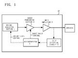
- Fig. 1 is a block diagram illustrating a tone control apparatus 10 according to a preferred embodiment of the present invention.
- the tone control apparatus 10 has a volume adjusting section 1, a boost processing section 2, a main amplifier 3, a clip detecting circuit (a detecting section) 4, and a microcomputer (a control section) 5.
- the volume adjusting section 1, the boost processing section 2, and the main amplifier 3 are realized by DSP, for example.
- An audio signal is input into the volume adjusting section 1, and the volume adjusting section 1 adjusts a volume level of the audio signal so as to output the audio signal to the boost processing section 2.
- the volume level is controlled according to an instruction from the microcomputer 5.
- the volume level can be set by a user's operation, and thus can be set according to 50 steps (1 to 50) one step by one step, for example.
- the boost processing section 2 executes an amplifying process (hereinafter, a boost process) on a predetermined frequency band (hereinafter, a boost band) of an audio signal supplied from the volume adjusting section 1, and outputs the audio signal to the main amplifier 3.
- the boost band is, for example, 80 Hz in a case of SBASS, and is 100 Hz in a case of BASS.
- a boost amount is controlled according to an instruction from the microcomputer 5.
- a boost value can be set by a user's operation, and can be set according to 6 steps (0, 1, 2, 3, 4 and 5), one step by one step, for example.
- the boost value is 2 dB per 1 step.
- the state that the boost value is 0 means that the boost process is cancelled by a user's operation.
- the main amplifier 3 executes an amplifying process on the audio signal supplied from the boost processing section 2 (namely, by way of the volume adjusting section 1 and the boost processing section 2), and outputs the audio signal (an output voltage) to a speaker and the clip detecting circuit 4.
- the clip detecting circuit 4 detects an amplitude value of the audio signal supplied from the main amplifier 3, and when the audio signal is clipped, it outputs a signal indicating that the clip is carried out to the microcomputer 5.
- the clip detecting circuit 4 detects whether the amplitude value of the audio signal is a first set value or more, and when it is the first set value or more, the clip detecting circuit 4 outputs a signal indicating that the amplitude value is the first set value or more to the microcomputer 5. On the other hand, when the amplitude value is less than the first set value, the clip detecting circuit 4 outputs a signal indicating that the amplitude value is less than the first set value.
- the clip detecting circuit 4 determines that the audio signal is not clipped, and outputs a signal indicating that the audio signal is not clipped to the microcomputer 5.
- the clip detecting circuit 4 determines that the audio signal might be clipped, and outputs a signal indicating that the audio signal is clipped to the microcomputer 5.
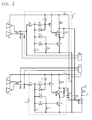
- Fig. 2 is a circuit diagram illustrating the main amplifier 3, the clip detecting circuit 4, and the speaker.
- the clip detecting circuit 4 includes a left-channel clip detecting circuit 4A and a right-channel clip detecting circuit 4B.
- the main amplifier 3 includes left-channel amplifiers A1 (positive-side amplifier) and A2 (negative-side amplifier), and right-channel amplifiers A11 (positive-side amplifier) and A12 (negative-side amplifier).
- An audio signal from the left-channel amplifier A1 is input into a positive-side input terminal of the left speaker SP1, and an audio signal from the left-channel amplifier A2 is input into a negative-side input terminal of the left speaker SP1.
- An audio signal from the left-channel amplifier A1 is input into the left-channel clip detecting circuit 4A.
- An audio signal from the right-channel amplifier A11 is input into a positive-side input terminal of the right speaker SP2, and an audio signal from the right-channel amplifier A12 is input into a negative-side input terminal of the right speaker SP2. Further, an audio signal from the right-channel amplifier A12 is input into the right-channel clip detecting circuit 4B.
- left-channel clip detecting circuit 4A and the right-channel clip detecting circuit 4B have the same circuit configuration, only the left-channel clip detecting circuit 4A will be described below.
- the clip detecting circuit 4A includes resistors R2 and R3, a first detecting section (a transistor Q1), resistors R4 and R5, a second detecting section (a transistor Q2), and a synthesizing section (a transistor Q3).
- the resistors R2 and R3 determine the first set value.
- the first detecting section (a transistor Q1) detects whether the amplitude value of an output voltage of the main amplifier 3 is the first set value or more.
- the resistors R4 and R5 determine the second set value.
- the second detecting section (a transistor Q2) detect whether the amplitude value of the output voltage of the main amplifier 3 is less than the second set value.
- the synthesizing section (a transistor Q3) synthesizes a detected result of the first detecting section with a detected result of the second detecting section.
- the transistor Q1 is a pnp type transistor, its emitter is connected to a +15 V power-supply line.
- a collector of the transistor Q1 is connected to a base of the transistor Q3, and its base is connected to a connecting point between the resistor R2 and the resistor R3.
- the transistor Q2 is an npn type transistor.
- An emitter of the transistor Q2 is connected to a ground potential, its collector is connected to an emitter of the transistor Q3, and its base is connected to a connecting point between the resistor R4 and the resistor R5.
- the transistor Q3 is an npn type transistor with built-in resistor.
- a base of the transistor Q3 is connected to the collector of the transistor Q1, and its collector is connected to the +15V power-supply line via the resistor R6.
- a transistor Q21 is a transistor for, when at least one of a signal from the left-channel clip detecting circuit 4A and a signal from the right-channel clip detecting circuit 4B is a signal indicating that the audio signal is clipped, supplying the signal indicating that the audio signal is clipped to the microcomputer 5.
- the microcomputer 5 sets the boost value, instructs the boost value set in the boost processing section 2, sets the volume level, and instructs the volume level set in the volume adjusting section 1.
- the microcomputer 5 receives a signal indicating that the audio signal is clipped (namely, the signal indicating that the audio signal has the first set value or more, or the signal indicating that the audio signal has less than the second set value) (for example, a low-level signal) from the clip detecting circuit 4 continuously for a predetermined time (for example, 5 milliseconds), the microcomputer 5 determines whether the set boost value is 0.
- the microcomputer 5 sets a value obtained by reducing a currently set boost value by a predetermined step (for example, 1 step) as a new boost value, and instructs the boost processing section 2 about the set boost value.
- a predetermined step for example, 1 step
- the microcomputer 5 sets a value obtained by reducing the currently set volume level by a predetermined step (for example, 1 step) as a new volume level, and instructs the volume adjusting section 1 about the new volume level.
- Fig. 3 is a time chart illustrating waveforms at respective points of the clip detecting circuit 4A, and respective symbols correspond to the waveforms at the respective points in Fig. 1 .
- An operation of the right-channel clip detecting circuit 4B is similar.
- the right-channel clip detecting circuit 4B does not detect that the audio signal is the first set value or more nor that the audio signal is less than the second set value. Therefore, a collector voltage of a transistor Q13 is at low level, and a signal is not output to a base of a transistor Q21.
- the amplitude value of the output voltage of the main amplifier 3 is less than the first set value, and is the second set value or more (see A point voltage). Therefore, a base voltage of the transistor Q1 reaches a continuity start voltage and the transistor Q 1 is in an ON state, a collector voltage is raised to a +15 V power-supply voltage, and a B point voltage is at a high level. On the other hand, a base voltage of the transistor Q2 reaches the continuity start voltage and the transistor Q2 is in the ON state, a collector voltage is reduced to a ground potential, and a C point voltage is at a low level.
- the B point voltage of the transistor Q3 Since the B point voltage of the transistor Q3 is at the high level, a base voltage reaches the continuity start voltage and the transistor Q3 is in the ON state, and a collector voltage is reduced to a ground potential. A base voltage of the transistor Q21 is less than the continuity start voltage, and thus the transistor Q21 is in an OFF state. Therefore, the +5 V power-supply voltage that is a high-level signal indicating that the audio signal is not clipped is output to the microcomputer 5. That is to say, a D point voltage is at the high level.
- the amplitude value of the output voltage of the main amplifier 3 is the first set value or more (see A point voltage). That is to say, it is considered that the amplitude of the audio signal is clipped on an upper side.
- the base voltage of the transistor Q1 does not reach the continuity start voltage and the transistor Q1 is in the OFF state, the collector is opened with respect to the + 15V power-supply voltage, and the B point voltage is at the low level.
- the base voltage of the transistor Q2 reaches the continuity start voltage and the transistor Q2 is in the ON state, the collector voltage is reduced to the ground potential, and the C point voltage is at the low level.
- the B point voltage of the transistor Q3 Since the B point voltage of the transistor Q3 is at low level, a base voltage of the transistor Q3 does not reach the continuity start voltage, the transistor Q3 is in the OFF state, and a collector voltage is raised to the +15V power-supply voltage.
- a collector voltage of the transistor Q3 is supplied to a base of the transistor Q21 via a diode D3.
- a base voltage of the transistor Q21 reaches of the continuity start voltage, and the transistor Q21 is in the ON state. Therefore, a ground potential as a low-level signal indicating that the audio signal is clipped (the amplitude of the audio signal is the first set value or more) is output to the microcomputer 5. That is to say, the D point voltage is at the low level.
- period T3 is the same as the period T1, the description about the period T1 will incorporate herein.
- the amplitude value of the output voltage of the main amplifier 3 is less than the second set value (see the A point voltage). That is to say, it is considered that the amplitude of the audio signal is clipped on a lower side. Therefore, the base voltage of the transistor Q1 reaches the continuity start voltage so that the transistor Q1 is in the ON state, the collector voltage is raised to the + 15 power-supply voltage, and the B point voltage is at the high level. On the other hand, the base voltage of the transistor Q2 does not reach the continuity start voltage so that the transistor Q2 is in the OFF state, and since the collector is opened with respect to the ground potential, the C point voltage is at the high level similarly to the B point voltage.
- the base voltage of the transistor Q3 reaches the continuity start voltage so that the transistor Q3 is in the ON state, and the collector voltage is at the high level.
- the collector voltage of the transistor Q3 is supplied to a base of the transistor Q21 via the diode D3.
- the base voltage of the transistor Q21 reaches the continuity start voltage so that the transistor Q21 is in the ON state. Therefore, the ground potential as a low-level signal indicating that the audio signal is clipped (the amplitude of the audio signal is less than the second set value) is output to the microcomputer 5. That is to say, the D point voltage is at the low level.
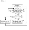
- Fig. 4 is a flowchart illustrating a process of the microcomputer 5.
- the microcomputer 5 determines whether the signal indicating that the audio signal is clipped (the low-level signal) is received from the clip detecting circuit 4 continuously for predetermined time (5 milliseconds) or more (S1).
- the microcomputer 5 determines whether the set boost value is 0 (S2). When the boost value is not 0 and the boost processing section 2 executes the boost process on the set boost value (NO at S2), the microcomputer 5 reduces the currently set boost value by a predetermined step (for example, 1 step), sets a new boost value, and instructs the boost processing section 2 about the set boost value (S3).
- the boost processing section 2 executes the boost process based on the new boost value instructed by the microcomputer 5. Therefore, the amplitude value of the audio signal from the main amplifier 3 can be reduced, so that the audio signal can be prevented from being clipped in advance. For example, when the currently set boost value is 3, 2 is set as the new boost value.
- the microcomputer 5 determines whether the signal (the low-level signal) indicating that the audio signal is clipped is received from the clip detecting circuit 4 continuously for predetermined time (5 milliseconds) (S1).
- the sequence goes to S3 again via S2. That is to say, the boost value is sequentially reduced by each 1 step every 5 milliseconds as long as the low-level signal is continued to be received from the clip detecting circuit 4.
- the microcomputer 5 reduces the currently set volume level by a predetermined step (for example, 1 step) so as to set a new volume level, and instructs the volume adjusting section 1 about the set volume level (S4).
- the volume adjusting section 1 adjusts the volume level of the audio signal based on the new volume level instructed by the microcomputer 5. Therefore, the amplitude value of the audio signal from the main amplifier 3 can be reduced, and the audio signal can be prevented from being clipped in advance. For example, when the currently set volume level is 30, 29 is set as a new volume level.
- Examples of the case where the set boost value is 0 include a case where the boost value is set to 0 by a user's operation, and a case where the boost value is sequentially reduced one step by one step by repeating steps S1, S2 and S3, and finally the boost value becomes 0.
- the microcomputer 5 determines whether the signal (the low-level signal) indicating that the audio signal is clipped is received from the clip detecting circuit 4 continuously for predetermined time (5 milliseconds) (S1).
- the sequence goes to S4 again via S2. That is to say, the volume level is sequentially reduced one step by one step every 5 milliseconds as long as the low-level signal is continued to be received from the clip detecting circuit 4.
- the amplitude value of the output voltage of the main amplifier 3 is always monitored, and when amplitude value is the first set value or more, or less than the second set value, the boost value is reduced.
- the boost value cannot be further reduced, the volume level is reduced, thereby securely preventing the output voltage of the main amplifier 3 from being clipped.
- the microcomputer instead of reducing the boost value until the boost value becomes 0 and reducing the volume level after the boost value becomes 0, the microcomputer reduces the boost value until the boost value becomes the predetermined value (for example, 2) and reduces the volume level after the boost value becomes the predetermined value.
- the predetermined value for example, 2
- the output voltage of the main amplifier 3 can be securely prevented from being clipped.
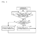
- Fig. 5 is a flowchart illustrating a process according to the embodiment.
- the microcomputer 5 determines whether the signal (the low-level signal) indicating that the audio signal is clipped is received from the clip detecting circuit 4 continuously for predetermined time (5 milliseconds) (S1).
- the microcomputer 5 determines whether the set boost value is the predetermined value (for example, 3) or more (S 12).
- the microcomputer 5 reduces the currently set boost value by a predetermined step (for example, 1 step), sets a new boost value, and instructs the boost processing section 2 about the set boost value (S3).
- the boost processing section 2 executes the boost process based on the new boost value instructed by the microcomputer 5. Therefore, the amplitude value of the audio signal from the main amplifier 3 can be reduced, and thus the audio signal can be prevented from being clipped in advance. For example, when the currently set boost value is 5, 4 is set as the new boost value.
- the microcomputer 5 determines whether the signal (the low-level signal) indicating that the audio signal is clipped is received from the clip detecting circuit 4 continuously for predetermined time (5 milliseconds) (S1).
- the sequence goes to S3 again via S12. That is to say, the boost value is sequentially reduced one step by one step every 5 milliseconds as long as the low-level signal is continued to be received from the clip detecting circuit 4.
- the microcomputer 5 reduces the currently set volume level by a predetermined step (for example, 1 step), sets a new volume level, and instructs the volume adjusting section 1 about the set volume level (S4).
- the volume adjusting section 1 adjusts the volume level of the audio signal based on the new volume level instructed by the microcomputer 5. Therefore, the amplitude value of the audio signal from the main amplifier 3 can be reduced, so that the audio signal can be prevented from being clipped in advance. For example, when the currently set volume level is 30, 29 is set as the new volume level.
- Examples of the case where the set boost value is less than the predetermined value include a case where the boost value is set to be less than the predetermined value by a user's operation, and a case where the boost value is sequentially reduced one step by one step by repeating steps S1, S12 and S3 so that finally the boost value is less than the predetermined value.
- the microcomputer 5 determines whether the signal (the low-level signal) indicating that the audio signal is clipped is received from the clip detecting circuit 4 continuously for predetermined time (5 milliseconds) (S1).
- the sequence goes to S4 again via S12. That is to say, the volume level is sequentially reduced one step by one step every 5 milliseconds as long as the low-level signal is continuously received from the clip detecting circuit 4.
- Fig. 6 is a flowchart illustrating the process according to the embodiment.
- the microcomputer 5 when the determination is firstly made as YES at S1, the microcomputer 5 saves the boost value and the volume level currently set by the user's operation in a memory, not shown.
- the microcomputer 5 determines whether reproduction of an audio signal for one tune (namely, one content) is completed (S21). When the reproduction of the audio signal for one tune is completed (YES at S21), the microcomputer 5 brings the boost value and the volume level that are set by the user's operation and are saved in the memory back to the setting state (S26).
- the microcomputer 5 determines whether an instruction for stopping the reproduction of the tune (audio signal) is input by a user's operation (S22). When the instruction for stopping the reproduction is input (YES at S22), the microcomputer 5 brings the boost value and the volume level that are set by the user's operation and are saved in the memory back to the setting state (S26).
- the microcomputer 5 determines whether the volume level is reduced by predetermined steps (for example, 10 steps) or more by a user's operation (S23). When the volume level is reduced by the predetermined steps or more by the user's operation (YES at S23), the microcomputer 5 brings the boost value and the volume level that are set by the user's operation and are saved in the memory back to the setting state (S26). The microcomputer 5 determines whether an input selector is changed (S24). For example, when a CD player and a DVD player are connected to an audio device using the tone control apparatus 10, a determination is made whether the device from which the audio signal is input to the tone control apparatus 10 is switched into the CD player or the DVD player.
- the microcomputer 5 brings the boost value and the volume level that are set by the user's operation and are saved in the memory back to the setting state (S26).
- the microcomputer 5 determines whether the power supply is brought into an OFF state (standby state) (S25). When the power supply is brought into the OFF state (standby state) (YES at S25), the microcomputer 5 brings the boost value and the volume level that are set by the user's operation and are saved in the memory back to the setting state (S26).
- the microcomputer 5 determines at S21 to S25 whether the currently input audio signal is not input, and when the audio signal is not input, it brings the boost value and the volume level that are set by the user's operation and are saved in the memory back to the setting state. As a result, the boost value and the volume level do not have to be reset to original values by the user's operation.
- the amplitude value of an audio signal to be input is small, and thus when a volume of a sound to be output is low, the setting is changed so that sensitivity of DSP is heightened by a user's operation.
- the setting should be changed so that the sensitivity of DSP is reduced by a user's operation. Therefore, the user's operations are complicated.
- improper setting is carried out, the volume of the sound becomes very low, or the audio signal is clipped so that a noise is generated.
- the sensitivity of DSP does not have to be switched by a user's operation, and the boost value and the volume level are reduced according to the amplitude value of an audio signal to be input. For this reason, an operation similar to an automatic change in the sensitivity of DSP can be performed.
- a constitution where the clip detecting circuit 4 detects only whether the audio signal has the first set value or more, and where the clip detecting circuit 4 does not detect whether the audio signal has less than the second set value may be employed.
- the resistors R4 and R5, the transistor Q2 and the like are omitted.
- a constitution where the clip detecting circuit 4 detects only whether an audio signal has less than the second set value, and where the clip detecting circuit 4 does not detect whether the audio signal has the first set value or more may be employed. In this case, in Fig.
- the resistors R2 and R3, the transistor Q1 and the like are omitted.
- Polarities of the respective transistors are not limited to the above embodiments. That is to say, in the time chart of Fig. 3 , the high level and the low level may be reversed.
- an AC-DC converter is used as the power supply in the present invention, an overcurrent can be prevented from being protected, and thus this case is effective.
Landscapes
- Circuit For Audible Band Transducer (AREA)
- Control Of Amplification And Gain Control (AREA)
- Tone Control, Compression And Expansion, Limiting Amplitude (AREA)
Applications Claiming Priority (2)
| Application Number | Priority Date | Filing Date | Title |
|---|---|---|---|
| JP2011005103 | 2011-01-13 | ||
| JP2011085827A JP5327481B2 (ja) | 2011-01-13 | 2011-04-07 | トーンコントロール装置 |
Publications (3)
| Publication Number | Publication Date |
|---|---|
| EP2477331A2 true EP2477331A2 (de) | 2012-07-18 |
| EP2477331A3 EP2477331A3 (de) | 2013-10-09 |
| EP2477331B1 EP2477331B1 (de) | 2016-03-09 |
Family
ID=45497733
Family Applications (1)
| Application Number | Title | Priority Date | Filing Date |
|---|---|---|---|
| EP11194640.6A Not-in-force EP2477331B1 (de) | 2011-01-13 | 2011-12-20 | Tonsteuerungsvorrichtung |
Country Status (3)
| Country | Link |
|---|---|
| US (1) | US8618403B2 (de) |
| EP (1) | EP2477331B1 (de) |
| JP (1) | JP5327481B2 (de) |
Families Citing this family (1)
| Publication number | Priority date | Publication date | Assignee | Title |
|---|---|---|---|---|
| JP5327481B2 (ja) * | 2011-01-13 | 2013-10-30 | オンキヨー株式会社 | トーンコントロール装置 |
Citations (1)
| Publication number | Priority date | Publication date | Assignee | Title |
|---|---|---|---|---|
| JP2010109845A (ja) | 2008-10-31 | 2010-05-13 | Onkyo Corp | トーンコントロール装置 |
Family Cites Families (15)
| Publication number | Priority date | Publication date | Assignee | Title |
|---|---|---|---|---|
| US3875334A (en) * | 1973-06-19 | 1975-04-01 | Motorola Inc | Multi-channel control circuit with D-C operated control devices |
| US4701957A (en) * | 1986-11-26 | 1987-10-20 | Smith Randall C | Dual mode music instrument preamplifier |
| JPH06103817B2 (ja) * | 1988-09-14 | 1994-12-14 | クラリオン株式会社 | 電子グラフィックイコライザ |
| US4912424A (en) * | 1989-06-12 | 1990-03-27 | Ford Motor Company | Audio amplifier with voltage limiting |
| US5255324A (en) | 1990-12-26 | 1993-10-19 | Ford Motor Company | Digitally controlled audio amplifier with voltage limiting |
| EP0539232A3 (en) * | 1991-10-24 | 1994-05-18 | Fernandes Co Ltd | An electric stringed instrument having a device for sustaining the vibration of a string and an electromagnetic driver for the device |
| US5541998A (en) * | 1994-10-20 | 1996-07-30 | Lar Electronics Corp. | Health club audio system |
| US6350943B1 (en) * | 2000-12-28 | 2002-02-26 | Korg, Inc. | Electric instrument amplifier |
| JP3975724B2 (ja) | 2001-11-02 | 2007-09-12 | オンキヨー株式会社 | トーンコントロール装置 |
| AU2003252703A1 (en) | 2002-07-29 | 2004-02-25 | Sharp Kabushiki Kaisha | Volume adjustment device, digital amplifier, and digital signal reproducing device |
| GB0410454D0 (en) | 2004-05-11 | 2004-06-16 | Radioscape Ltd | Automatic selection of audio-equaliser parameters dependent on broadcast programme type information |
| US20060153405A1 (en) | 2005-01-13 | 2006-07-13 | Myers Bruce A | Audio automatic volume control |
| EP2232700B1 (de) * | 2007-12-21 | 2014-08-13 | Dts Llc | System zur einstellung der wahrgenommenen lautstärke von tonsignalen |
| JP5327481B2 (ja) * | 2011-01-13 | 2013-10-30 | オンキヨー株式会社 | トーンコントロール装置 |
| WO2013101605A1 (en) * | 2011-12-27 | 2013-07-04 | Dts Llc | Bass enhancement system |
-
2011
- 2011-04-07 JP JP2011085827A patent/JP5327481B2/ja not_active Expired - Fee Related
- 2011-12-05 US US13/311,348 patent/US8618403B2/en not_active Expired - Fee Related
- 2011-12-20 EP EP11194640.6A patent/EP2477331B1/de not_active Not-in-force
Patent Citations (1)
| Publication number | Priority date | Publication date | Assignee | Title |
|---|---|---|---|---|
| JP2010109845A (ja) | 2008-10-31 | 2010-05-13 | Onkyo Corp | トーンコントロール装置 |
Also Published As
| Publication number | Publication date |
|---|---|
| US20120180620A1 (en) | 2012-07-19 |
| EP2477331B1 (de) | 2016-03-09 |
| JP2012161064A (ja) | 2012-08-23 |
| US8618403B2 (en) | 2013-12-31 |
| EP2477331A3 (de) | 2013-10-09 |
| JP5327481B2 (ja) | 2013-10-30 |
Similar Documents
| Publication | Publication Date | Title |
|---|---|---|
| EP2487930B1 (de) | Tonsignalausgabevorrichtung und Tonsignalausgabeverfahren | |
| US20100322438A1 (en) | Method and circuit for controlling an output of an audio signal of a battery-powered device | |
| US8130972B2 (en) | Audio reproducing apparatus and program | |
| US20120163614A1 (en) | Sound signal output device, speaker device, sound output device, and sound signal output method | |
| US8155349B2 (en) | Muting control device, muting control method, and muting control program | |
| US20040068402A1 (en) | Digital audio processor | |
| JP2009065550A (ja) | 電子ボリウム装置およびそれを用いたオーディオ機器、ならびに異常検出方法 | |
| US9166544B2 (en) | Volume control apparatus with first and second controllers | |
| US8618403B2 (en) | Tone control apparatus | |
| GB2457986A (en) | Acoustic echo cancellation | |
| US10630240B2 (en) | Amplifier, audio device and control method | |
| EP3379847B1 (de) | Audiogerät, lautsprecher und audiosignalverarbeitungsverfahren | |
| US20150244333A1 (en) | Adaptive rail voltage regulation on power supplies | |
| JP2011155333A (ja) | 信号処理回路 | |
| KR100936227B1 (ko) | 전자장치 및 그 제어방법 | |
| US8130982B2 (en) | Signal amplifying apparatus, amplification system, and signal amplification method | |
| JP4661422B2 (ja) | ミューティング装置、デジタルオーディオ装置 | |
| JP2009088831A (ja) | 音声出力装置 | |
| CN113596699B (zh) | 一种音频输入检测电路及方法 | |
| JP6143624B2 (ja) | スピーカ切替装置およびオーディオ機器 | |
| JP4230332B2 (ja) | オーディオ機器およびオーディオシステム | |
| KR0136701B1 (ko) | 오디오 시스템의 초기 증폭 레벨 조정 방법 | |
| KR100752021B1 (ko) | 팝 노이즈 제거장치 및 방법 | |
| US20090016546A1 (en) | Audio control apparatus | |
| JP4610433B2 (ja) | オーディオシステム用セットアップ装置、オーディオシステム用セットアップ方法及びプログラム |
Legal Events
| Date | Code | Title | Description |
|---|---|---|---|
| PUAI | Public reference made under article 153(3) epc to a published international application that has entered the european phase |
Free format text: ORIGINAL CODE: 0009012 |
|
| AK | Designated contracting states |
Kind code of ref document: A2 Designated state(s): AL AT BE BG CH CY CZ DE DK EE ES FI FR GB GR HR HU IE IS IT LI LT LU LV MC MK MT NL NO PL PT RO RS SE SI SK SM TR |
|
| AX | Request for extension of the european patent |
Extension state: BA ME |
|
| RIC1 | Information provided on ipc code assigned before grant |
Ipc: H03G 9/02 20060101ALI20130418BHEP Ipc: H03G 9/14 20060101ALI20130418BHEP Ipc: H03G 9/18 20060101AFI20130418BHEP |
|
| PUAL | Search report despatched |
Free format text: ORIGINAL CODE: 0009013 |
|
| AK | Designated contracting states |
Kind code of ref document: A3 Designated state(s): AL AT BE BG CH CY CZ DE DK EE ES FI FR GB GR HR HU IE IS IT LI LT LU LV MC MK MT NL NO PL PT RO RS SE SI SK SM TR |
|
| AX | Request for extension of the european patent |
Extension state: BA ME |
|
| RIC1 | Information provided on ipc code assigned before grant |
Ipc: H03G 9/14 20060101ALI20130905BHEP Ipc: H03G 9/02 20060101ALI20130905BHEP Ipc: H03G 9/18 20060101AFI20130905BHEP |
|
| 17P | Request for examination filed |
Effective date: 20140327 |
|
| RBV | Designated contracting states (corrected) |
Designated state(s): AL AT BE BG CH CY CZ DE DK EE ES FI FR GB GR HR HU IE IS IT LI LT LU LV MC MK MT NL NO PL PT RO RS SE SI SK SM TR |
|
| GRAP | Despatch of communication of intention to grant a patent |
Free format text: ORIGINAL CODE: EPIDOSNIGR1 |
|
| INTG | Intention to grant announced |
Effective date: 20151019 |
|
| GRAS | Grant fee paid |
Free format text: ORIGINAL CODE: EPIDOSNIGR3 |
|
| GRAA | (expected) grant |
Free format text: ORIGINAL CODE: 0009210 |
|
| AK | Designated contracting states |
Kind code of ref document: B1 Designated state(s): AL AT BE BG CH CY CZ DE DK EE ES FI FR GB GR HR HU IE IS IT LI LT LU LV MC MK MT NL NO PL PT RO RS SE SI SK SM TR |
|
| REG | Reference to a national code |
Ref country code: GB Ref legal event code: FG4D |
|
| REG | Reference to a national code |
Ref country code: AT Ref legal event code: REF Ref document number: 780150 Country of ref document: AT Kind code of ref document: T Effective date: 20160315 Ref country code: CH Ref legal event code: EP |
|
| REG | Reference to a national code |
Ref country code: IE Ref legal event code: FG4D |
|
| REG | Reference to a national code |
Ref country code: DE Ref legal event code: R096 Ref document number: 602011023812 Country of ref document: DE |
|
| REG | Reference to a national code |
Ref country code: LT Ref legal event code: MG4D |
|
| REG | Reference to a national code |
Ref country code: NL Ref legal event code: MP Effective date: 20160309 |
|
| PG25 | Lapsed in a contracting state [announced via postgrant information from national office to epo] |
Ref country code: ES Free format text: LAPSE BECAUSE OF FAILURE TO SUBMIT A TRANSLATION OF THE DESCRIPTION OR TO PAY THE FEE WITHIN THE PRESCRIBED TIME-LIMIT Effective date: 20160309 Ref country code: NO Free format text: LAPSE BECAUSE OF FAILURE TO SUBMIT A TRANSLATION OF THE DESCRIPTION OR TO PAY THE FEE WITHIN THE PRESCRIBED TIME-LIMIT Effective date: 20160609 Ref country code: HR Free format text: LAPSE BECAUSE OF FAILURE TO SUBMIT A TRANSLATION OF THE DESCRIPTION OR TO PAY THE FEE WITHIN THE PRESCRIBED TIME-LIMIT Effective date: 20160309 Ref country code: FI Free format text: LAPSE BECAUSE OF FAILURE TO SUBMIT A TRANSLATION OF THE DESCRIPTION OR TO PAY THE FEE WITHIN THE PRESCRIBED TIME-LIMIT Effective date: 20160309 Ref country code: GR Free format text: LAPSE BECAUSE OF FAILURE TO SUBMIT A TRANSLATION OF THE DESCRIPTION OR TO PAY THE FEE WITHIN THE PRESCRIBED TIME-LIMIT Effective date: 20160610 |
|
| REG | Reference to a national code |
Ref country code: AT Ref legal event code: MK05 Ref document number: 780150 Country of ref document: AT Kind code of ref document: T Effective date: 20160309 |
|
| PG25 | Lapsed in a contracting state [announced via postgrant information from national office to epo] |
Ref country code: PL Free format text: LAPSE BECAUSE OF FAILURE TO SUBMIT A TRANSLATION OF THE DESCRIPTION OR TO PAY THE FEE WITHIN THE PRESCRIBED TIME-LIMIT Effective date: 20160309 Ref country code: LV Free format text: LAPSE BECAUSE OF FAILURE TO SUBMIT A TRANSLATION OF THE DESCRIPTION OR TO PAY THE FEE WITHIN THE PRESCRIBED TIME-LIMIT Effective date: 20160309 Ref country code: SE Free format text: LAPSE BECAUSE OF FAILURE TO SUBMIT A TRANSLATION OF THE DESCRIPTION OR TO PAY THE FEE WITHIN THE PRESCRIBED TIME-LIMIT Effective date: 20160309 Ref country code: RS Free format text: LAPSE BECAUSE OF FAILURE TO SUBMIT A TRANSLATION OF THE DESCRIPTION OR TO PAY THE FEE WITHIN THE PRESCRIBED TIME-LIMIT Effective date: 20160309 Ref country code: LT Free format text: LAPSE BECAUSE OF FAILURE TO SUBMIT A TRANSLATION OF THE DESCRIPTION OR TO PAY THE FEE WITHIN THE PRESCRIBED TIME-LIMIT Effective date: 20160309 Ref country code: NL Free format text: LAPSE BECAUSE OF FAILURE TO SUBMIT A TRANSLATION OF THE DESCRIPTION OR TO PAY THE FEE WITHIN THE PRESCRIBED TIME-LIMIT Effective date: 20160309 |
|
| PG25 | Lapsed in a contracting state [announced via postgrant information from national office to epo] |
Ref country code: EE Free format text: LAPSE BECAUSE OF FAILURE TO SUBMIT A TRANSLATION OF THE DESCRIPTION OR TO PAY THE FEE WITHIN THE PRESCRIBED TIME-LIMIT Effective date: 20160309 Ref country code: IS Free format text: LAPSE BECAUSE OF FAILURE TO SUBMIT A TRANSLATION OF THE DESCRIPTION OR TO PAY THE FEE WITHIN THE PRESCRIBED TIME-LIMIT Effective date: 20160709 |
|
| REG | Reference to a national code |
Ref country code: FR Ref legal event code: PLFP Year of fee payment: 6 |
|
| PG25 | Lapsed in a contracting state [announced via postgrant information from national office to epo] |
Ref country code: AT Free format text: LAPSE BECAUSE OF FAILURE TO SUBMIT A TRANSLATION OF THE DESCRIPTION OR TO PAY THE FEE WITHIN THE PRESCRIBED TIME-LIMIT Effective date: 20160309 Ref country code: CZ Free format text: LAPSE BECAUSE OF FAILURE TO SUBMIT A TRANSLATION OF THE DESCRIPTION OR TO PAY THE FEE WITHIN THE PRESCRIBED TIME-LIMIT Effective date: 20160309 Ref country code: RO Free format text: LAPSE BECAUSE OF FAILURE TO SUBMIT A TRANSLATION OF THE DESCRIPTION OR TO PAY THE FEE WITHIN THE PRESCRIBED TIME-LIMIT Effective date: 20160309 Ref country code: PT Free format text: LAPSE BECAUSE OF FAILURE TO SUBMIT A TRANSLATION OF THE DESCRIPTION OR TO PAY THE FEE WITHIN THE PRESCRIBED TIME-LIMIT Effective date: 20160711 Ref country code: SM Free format text: LAPSE BECAUSE OF FAILURE TO SUBMIT A TRANSLATION OF THE DESCRIPTION OR TO PAY THE FEE WITHIN THE PRESCRIBED TIME-LIMIT Effective date: 20160309 Ref country code: SK Free format text: LAPSE BECAUSE OF FAILURE TO SUBMIT A TRANSLATION OF THE DESCRIPTION OR TO PAY THE FEE WITHIN THE PRESCRIBED TIME-LIMIT Effective date: 20160309 |
|
| REG | Reference to a national code |
Ref country code: DE Ref legal event code: R097 Ref document number: 602011023812 Country of ref document: DE |
|
| PG25 | Lapsed in a contracting state [announced via postgrant information from national office to epo] |
Ref country code: BE Free format text: LAPSE BECAUSE OF FAILURE TO SUBMIT A TRANSLATION OF THE DESCRIPTION OR TO PAY THE FEE WITHIN THE PRESCRIBED TIME-LIMIT Effective date: 20160309 Ref country code: IT Free format text: LAPSE BECAUSE OF FAILURE TO SUBMIT A TRANSLATION OF THE DESCRIPTION OR TO PAY THE FEE WITHIN THE PRESCRIBED TIME-LIMIT Effective date: 20160309 |
|
| PLBE | No opposition filed within time limit |
Free format text: ORIGINAL CODE: 0009261 |
|
| STAA | Information on the status of an ep patent application or granted ep patent |
Free format text: STATUS: NO OPPOSITION FILED WITHIN TIME LIMIT |
|
| PG25 | Lapsed in a contracting state [announced via postgrant information from national office to epo] |
Ref country code: DK Free format text: LAPSE BECAUSE OF FAILURE TO SUBMIT A TRANSLATION OF THE DESCRIPTION OR TO PAY THE FEE WITHIN THE PRESCRIBED TIME-LIMIT Effective date: 20160309 |
|
| 26N | No opposition filed |
Effective date: 20161212 |
|
| PG25 | Lapsed in a contracting state [announced via postgrant information from national office to epo] |
Ref country code: BG Free format text: LAPSE BECAUSE OF FAILURE TO SUBMIT A TRANSLATION OF THE DESCRIPTION OR TO PAY THE FEE WITHIN THE PRESCRIBED TIME-LIMIT Effective date: 20160609 |
|
| PG25 | Lapsed in a contracting state [announced via postgrant information from national office to epo] |
Ref country code: SI Free format text: LAPSE BECAUSE OF FAILURE TO SUBMIT A TRANSLATION OF THE DESCRIPTION OR TO PAY THE FEE WITHIN THE PRESCRIBED TIME-LIMIT Effective date: 20160309 |
|
| REG | Reference to a national code |
Ref country code: CH Ref legal event code: PL |
|
| PG25 | Lapsed in a contracting state [announced via postgrant information from national office to epo] |
Ref country code: MC Free format text: LAPSE BECAUSE OF FAILURE TO SUBMIT A TRANSLATION OF THE DESCRIPTION OR TO PAY THE FEE WITHIN THE PRESCRIBED TIME-LIMIT Effective date: 20160309 |
|
| REG | Reference to a national code |
Ref country code: IE Ref legal event code: MM4A |
|
| PG25 | Lapsed in a contracting state [announced via postgrant information from national office to epo] |
Ref country code: LU Free format text: LAPSE BECAUSE OF NON-PAYMENT OF DUE FEES Effective date: 20161220 Ref country code: LI Free format text: LAPSE BECAUSE OF NON-PAYMENT OF DUE FEES Effective date: 20161231 Ref country code: CH Free format text: LAPSE BECAUSE OF NON-PAYMENT OF DUE FEES Effective date: 20161231 |
|
| REG | Reference to a national code |
Ref country code: FR Ref legal event code: PLFP Year of fee payment: 7 |
|
| PG25 | Lapsed in a contracting state [announced via postgrant information from national office to epo] |
Ref country code: IE Free format text: LAPSE BECAUSE OF NON-PAYMENT OF DUE FEES Effective date: 20161220 |
|
| PG25 | Lapsed in a contracting state [announced via postgrant information from national office to epo] |
Ref country code: HU Free format text: LAPSE BECAUSE OF FAILURE TO SUBMIT A TRANSLATION OF THE DESCRIPTION OR TO PAY THE FEE WITHIN THE PRESCRIBED TIME-LIMIT; INVALID AB INITIO Effective date: 20111220 Ref country code: CY Free format text: LAPSE BECAUSE OF FAILURE TO SUBMIT A TRANSLATION OF THE DESCRIPTION OR TO PAY THE FEE WITHIN THE PRESCRIBED TIME-LIMIT Effective date: 20160309 |
|
| PG25 | Lapsed in a contracting state [announced via postgrant information from national office to epo] |
Ref country code: TR Free format text: LAPSE BECAUSE OF FAILURE TO SUBMIT A TRANSLATION OF THE DESCRIPTION OR TO PAY THE FEE WITHIN THE PRESCRIBED TIME-LIMIT Effective date: 20160309 Ref country code: MK Free format text: LAPSE BECAUSE OF FAILURE TO SUBMIT A TRANSLATION OF THE DESCRIPTION OR TO PAY THE FEE WITHIN THE PRESCRIBED TIME-LIMIT Effective date: 20160309 |
|
| PG25 | Lapsed in a contracting state [announced via postgrant information from national office to epo] |
Ref country code: MT Free format text: LAPSE BECAUSE OF NON-PAYMENT OF DUE FEES Effective date: 20161220 |
|
| PG25 | Lapsed in a contracting state [announced via postgrant information from national office to epo] |
Ref country code: AL Free format text: LAPSE BECAUSE OF FAILURE TO SUBMIT A TRANSLATION OF THE DESCRIPTION OR TO PAY THE FEE WITHIN THE PRESCRIBED TIME-LIMIT Effective date: 20160309 |
|
| PGFP | Annual fee paid to national office [announced via postgrant information from national office to epo] |
Ref country code: DE Payment date: 20191210 Year of fee payment: 9 |
|
| PGFP | Annual fee paid to national office [announced via postgrant information from national office to epo] |
Ref country code: FR Payment date: 20191115 Year of fee payment: 9 |
|
| PGFP | Annual fee paid to national office [announced via postgrant information from national office to epo] |
Ref country code: GB Payment date: 20191219 Year of fee payment: 9 |
|
| REG | Reference to a national code |
Ref country code: DE Ref legal event code: R119 Ref document number: 602011023812 Country of ref document: DE |
|
| GBPC | Gb: european patent ceased through non-payment of renewal fee |
Effective date: 20201220 |
|
| PG25 | Lapsed in a contracting state [announced via postgrant information from national office to epo] |
Ref country code: FR Free format text: LAPSE BECAUSE OF NON-PAYMENT OF DUE FEES Effective date: 20201231 |
|
| PG25 | Lapsed in a contracting state [announced via postgrant information from national office to epo] |
Ref country code: GB Free format text: LAPSE BECAUSE OF NON-PAYMENT OF DUE FEES Effective date: 20201220 Ref country code: DE Free format text: LAPSE BECAUSE OF NON-PAYMENT OF DUE FEES Effective date: 20210701 |