US8618403B2 - Tone control apparatus - Google Patents
Tone control apparatus Download PDFInfo
- Publication number
- US8618403B2 US8618403B2 US13/311,348 US201113311348A US8618403B2 US 8618403 B2 US8618403 B2 US 8618403B2 US 201113311348 A US201113311348 A US 201113311348A US 8618403 B2 US8618403 B2 US 8618403B2
- Authority
- US
- United States
- Prior art keywords
- value
- boost
- audio signal
- section
- volume level
- Prior art date
- Legal status (The legal status is an assumption and is not a legal conclusion. Google has not performed a legal analysis and makes no representation as to the accuracy of the status listed.)
- Expired - Fee Related, expires
Links
Images


Classifications
-
- H—ELECTRICITY
- H03—ELECTRONIC CIRCUITRY
- H03G—CONTROL OF AMPLIFICATION
- H03G9/00—Combinations of two or more types of control, e.g. gain control and tone control
- H03G9/02—Combinations of two or more types of control, e.g. gain control and tone control in untuned amplifiers
- H03G9/12—Combinations of two or more types of control, e.g. gain control and tone control in untuned amplifiers having semiconductor devices
- H03G9/18—Combinations of two or more types of control, e.g. gain control and tone control in untuned amplifiers having semiconductor devices for tone control and volume expansion or compression
-
- H—ELECTRICITY
- H03—ELECTRONIC CIRCUITRY
- H03G—CONTROL OF AMPLIFICATION
- H03G9/00—Combinations of two or more types of control, e.g. gain control and tone control
- H03G9/02—Combinations of two or more types of control, e.g. gain control and tone control in untuned amplifiers
- H03G9/025—Combinations of two or more types of control, e.g. gain control and tone control in untuned amplifiers frequency-dependent volume compression or expansion, e.g. multiple-band systems
-
- H—ELECTRICITY
- H03—ELECTRONIC CIRCUITRY
- H03G—CONTROL OF AMPLIFICATION
- H03G9/00—Combinations of two or more types of control, e.g. gain control and tone control
- H03G9/02—Combinations of two or more types of control, e.g. gain control and tone control in untuned amplifiers
- H03G9/12—Combinations of two or more types of control, e.g. gain control and tone control in untuned amplifiers having semiconductor devices
- H03G9/14—Combinations of two or more types of control, e.g. gain control and tone control in untuned amplifiers having semiconductor devices for gain control and tone control
Definitions
- the present invention relates to a tone control apparatus for executing a boost process on a predetermined band of a signal.
- Audio devices employ tone control apparatuses for executing a tone control process such as a boost process for increasing levels of predetermined frequency bands.
- a tone control process such as a boost process for increasing levels of predetermined frequency bands.
- FIGS. 7B and 7C when an amplitude value of an audio signal is large, an audio signal in a boost band is in a clip state at a supply voltage, and thus an audio output from a speaker is distorted.
- a tone control apparatus described in JP publication number 2010-109845.
- a first detecting section and a second detecting section detect a case where an output voltage of an amplifying section has a first set value or more and a case where the output voltage has less than a second set value. That is to say, a case where the output voltage of the amplifying section is clipped to a high-level side, and a case where the output voltage is clipped to a low-level side are detected.
- a synthesizing section synthesizes these detected results, and a switching section switches a boost amount of a boost processing section based on an output voltage of the synthesizing section.
- the boost amount is switched into a second boost value smaller than a normal first boost value. For this reason, the output voltage of the amplifying section can be prevented from being clipped without reducing an amplitude of all bands.
- a tone control apparatus of the preferred embodiment of the present invention comprises: a volume adjusting section for adjusting a volume level of an audio signal to a volume level set by a control section; a boost processing section for executing a boost process so that a boost band of the audio signal has a boost value set by the control section; an amplifying section for amplifying the audio signal via the volume adjusting section and the boost processing section; a detecting section for detecting whether the audio signal output from the amplifying section has a first set value or more, and when the audio signal has the first set value or more, outputting a signal representing that the audio signal has the first set value or more to the control section; and the control section for, when receiving the signal representing that the audio signal has the first set value or more from the detecting section, determining whether the set boost value is a predetermined value or more, and when the set boost value is the predetermined value or more, reducing the currently set boost value by a predetermined step so as to set a new boost value, and when the set boost value is less than the
- a boost value is the predetermined value or more
- a currently set boost value is reduced by a predetermined step, so that a new boost value is set. Therefore, when the detecting section detects that an audio signal has the first set value or more, the boost value to be set is reduced by each predetermined step, and thus clip can be prevented in advance. Further, when the boost value is less than the predetermined value, a currently set volume level is reduced by a predetermined step, and a new volume level is set.
- the audio signal is still the first set value or more, the volume level is further reduced by each predetermined step. Therefore, an audio signal can be securely prevented from being clipped.
- control section determines whether the set boost value is a predetermined value or more.
- control section determines whether the set boost value is 0, and when the set boost value is not 0, the control section reduces the currently set boost value by a predetermined step so as to set a new boost value, and when the currently set boost value is 0, reduces the currently volume level by a predetermined step so as to set a new volume level.
- the detecting section further detects whether the audio signal output from the amplifying section has less than a second set value smaller than the first set value, and when the audio signal has less than the second set value, the detecting section outputs a signal representing that the audio signal has less than the second set value to the control section, when the control section receives the signal representing that the audio signal has less than the second set value from the detecting section, the control section determines whether the set boost value is a predetermined value or more, and when the set boost value is the predetermined value or more, the control section reduces the currently set boost value by a predetermined step so as to set a new boost value, and when the set boost value is less than the predetermined value, the control section reduces the currently set volume level by a predetermined step so as to set a new volume level.
- the control section determines whether the set boost value is 0, when the set boost value is not 0, the control section reduces the currently set boost value by a predetermined step so as to set new boost value, and when the set boost value is 0, the control section reduces the currently set volume level by a predetermined step so as to set a new volume level.
- the control section when the control section reduces the boost value currently set by a user's operation by the predetermined step so as to set the new boost value, the control section stores the boost value set by the user's operation in a storage section, and when the control section reduces the volume level currently set by the user's operation by the predetermined step so as to set the new volume level, the control section stores the volume level set by the user's operation in the storage section, and when the currently input audio signal is not input, the control section brings the boost value and the volume level stored in the storage section back to a setting state.
- the original boost value and volume level can be automatically restored without a user's operation.
- a tone control apparatus of the preferred embodiment of the present invention comprises: a volume adjusting section for adjusting a volume level of an audio signal to a volume level set by a control section; a boost processing section for executing a boost process so that a boost band of the audio signal has a boost value set by the control section; an amplifying section for amplifying the audio signal via the volume adjusting section and the boost processing section; a detecting section for detecting whether the audio signal output from the amplifying section has less than a second set value, and when the audio signal has less than the second set value, outputting a signal representing that the audio signal has less than the second set value to the control section; and the control section, for when receiving the signal representing that the audio signal has less than the second set value, determining whether the boost value is a predetermined value or more, and when the set boost value is the predetermined value or more, reducing the currently set boost value by a predetermined step so as to set a new boost value, and when the set boost value is less than the predetermined value, reducing
- a tone control apparatus of the preferred embodiment of the present invention comprises: a volume adjusting section for adjusting a volume level of an audio signal to a volume level set by a control section; a boost processing section for executing a boost process so that a boost band of the audio signal has a boost value set by the control section; an amplifying section for amplifying the audio signal via the volume adjusting section and the boost processing section; a detecting section for detecting whether the audio signal output from the amplifying section has a first set value or more, and when the audio signal has the first set value or more, outputting a signal representing that the audio signal has the first set value or more to the control section; and the control section for, when receiving the signal representing that the audio signal has the first set value or more, determining whether the set boost value is 0, and when the set boost value is not 0, reducing the currently set boost value by a predetermined step so as to set a new boost value, and when the set boost value is 0, reducing the currently set volume level by a predetermined step so as to set a
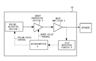
- FIG. 1 is a block diagram illustrating a tone control apparatus according to a preferred embodiment of the present invention
- FIG. 2 is a circuit diagram illustrating a clip detecting circuit
- FIG. 3 is a time chart illustrating waveforms at respective points of the clip detecting circuit
- FIG. 4 is a flowchart illustrating a process of a microcomputer (a control section);
- FIG. 5 is a flowchart illustrating a process of the microcomputer (the control section);
- FIG. 6 is a flowchart illustrating a process of the microcomputer (the control section).
- FIGS. 7A to 7C are diagrams describing states that an audio signal is clipped.
- FIG. 1 is a block diagram illustrating a tone control apparatus 10 according to a preferred embodiment of the present invention.
- the tone control apparatus 10 has a volume adjusting section 1 , a boost processing section 2 , a main amplifier 3 , a clip detecting circuit (a detecting section) 4 , and a microcomputer (a control section) 5 .
- the volume adjusting section 1 , the boost processing section 2 , and the main amplifier 3 are realized by DSP, for example.
- An audio signal is input into the volume adjusting section 1 , and the volume adjusting section 1 adjusts a volume level of the audio signal so as to output the audio signal to the boost processing section 2 .
- the volume level is controlled according to an instruction from the microcomputer 5 .
- the volume level can be set by a user's operation, and thus can be set according to 50 steps (1 to 50) one step by one step, for example.
- the boost processing section 2 executes an amplifying process (hereinafter, a boost process) on a predetermined frequency band (hereinafter, a boost band) of an audio signal supplied from the volume adjusting section 1 , and outputs the audio signal to the main amplifier 3 .
- the boost band is, for example, 80 Hz in a case of SBASS, and is 100 Hz in a case of BASS.
- a boost amount is controlled according to an instruction from the microcomputer 5 .
- a boost value can be set by a user's operation, and can be set according to 6 steps (0, 1, 2, 3, 4 and 5), one step by one step, for example.
- the boost value is 2 dB per 1 step.
- the state that the boost value is 0 means that the boost process is cancelled by a user's operation.
- the main amplifier 3 executes an amplifying process on the audio signal supplied from the boost processing section (namely, by way of the volume adjusting section 1 and the boost processing section 2 ), and outputs the audio signal (an output voltage) to a speaker and the clip detecting circuit 4 .
- the clip detecting circuit 4 detects an amplitude value of the audio signal supplied from the main amplifier 3 , and when the audio signal is clipped, it outputs a signal representing that the clip is carried out to the microcomputer 5 .
- the clip detecting circuit 4 detects whether the amplitude value of the audio signal is a first set value or more, and when it is the first set value or more, the clip detecting circuit 4 outputs a signal representing that the amplitude value is the first set value or more to the microcomputer 5 . On the other hand, when the amplitude value is less than the first set value, the clip detecting circuit 4 outputs a signal representing that the amplitude value is less than the first set value.
- the clip detecting circuit 4 determines that the audio signal is not clipped, and outputs a signal representing that the audio signal is not clipped to the microcomputer 5 .
- the clip detecting circuit 4 determines that the audio signal might be clipped, and outputs a signal representing that the audio signal is clipped to the microcomputer 5 .
- FIG. 2 is a circuit diagram illustrating the main amplifier 3 , the clip detecting circuit 4 , and the speaker.
- the clip detecting circuit 4 includes a left-channel clip detecting circuit 4 A and a right-channel clip detecting circuit 4 B.
- the main amplifier 3 includes left-channel amplifiers A 1 (positive-side amplifier) and A 2 (negative-side amplifier), and right-channel amplifiers A 11 (positive-side amplifier) and A 12 (negative-side amplifier).
- An audio signal from the left-channel amplifier Al is input into a positive-side input terminal of the left speaker SP 1
- an audio signal from the left-channel amplifier A 2 is input into a negative-side input terminal of the left speaker SP 1 .
- An audio signal from the left-channel amplifier A 1 is input into the left-channel clip detecting circuit 4 A.
- An audio signal from the right-channel amplifier A 11 is input into a positive-side input terminal of the right speaker SP 2
- an audio signal from the right-channel amplifier A 12 is input into a negative-side input terminal of the right speaker SP 2 .
- an audio signal from the right-channel amplifier A 12 is input into the right-channel clip detecting circuit 4 B.
- left-channel clip detecting circuit 4 A and the right-channel clip detecting circuit 4 B have the same circuit configuration, only the left-channel clip detecting circuit 4 A will be described below.
- the clip detecting circuit 4 A approximately includes resistors R 2 and R 3 , a first detecting section (a transistor Q 1 ), resistors R 4 and R 5 , a second detecting section (a transistor Q 2 ), and a synthesizing section (a transistor Q 3 ).
- the resistors R 2 and R 3 determine the first set value.
- the first detecting section (a transistor Q 1 ) detects whether the amplitude value of an output voltage of the main amplifier 3 is the first set value or more.
- the resistors R 4 and R 5 determine the second set value.
- the second detecting section (a transistor Q 2 ) detect whether the amplitude value of the output voltage of the main amplifier 3 is less than the second set value.
- the synthesizing section (a transistor Q 3 ) synthesizes a detected result of the first detecting section with a detected result of the second detecting section.
- the transistor Q 1 is a pnp type transistor, its emitter is connected to a +15 V power-supply line.
- a collector of the transistor Q 1 is connected to a base of the transistor Q 3 , and its base is connected to a connecting point between the resistor R 2 and the resistor R 3 .
- the transistor Q 2 is an npn type transistor.
- An emitter of the transistor Q 2 is connected to a ground potential, its collector is connected to an emitter of the transistor Q 3 , and its base is connected to a connecting point between the resistor R 4 and the resistor R 5 .
- the transistor Q 3 is an npn type transistor with built-in resistor.
- a base of the transistor Q 3 is connected to the collector of the transistor Q 1 , and its collector is connected to the +15V power-supply line via the resistor R 6 .
- a transistor Q 21 is a transistor for, when at least one of a signal from the left-channel clip detecting circuit 4 A and a signal from the right-channel clip detecting circuit 4 B is a signal representing that the audio signal is clipped, supplying the signal representing that the audio signal is clipped to the microcomputer 5 .
- the microcomputer 5 sets the boost value, instructs the boost value set in the boost processing section 2 , sets the volume level, and instructs the volume level set in the volume adjusting section 1 .
- the microcomputer 5 receives a signal representing that the audio signal is clipped (namely, the signal representing that the audio signal has the first set value or more, or the signal representing that the audio signal has less than the second set value) (for example, a low-level signal) from the clip detecting circuit 4 continuously for a predetermined time (for example, 5 milliseconds), the microcomputer 5 determines whether the set boost value is 0.
- the microcomputer 5 sets a value obtained by reducing a currently set boost value by a predetermined step (for example, 1 step) as a new boost value, and instructs the boost processing section 2 about the set boost value.
- a predetermined step for example, 1 step
- the microcomputer 5 sets a value obtained by reducing the currently set volume level by a predetermined step (for example, 1 step) as a new volume level, and instructs the volume adjusting section 1 about the new volume level.
- FIG. 3 is a time chart illustrating waveforms at respective points of the clip detecting circuit 4 A, and respective symbols correspond to the waveforms at the respective points in FIG. 1 .
- An operation of the right-channel clip detecting circuit 4 B is similar.
- the right-channel clip detecting circuit 4 B does not detect that the audio signal is the first set value or more nor that the audio signal is less than the second set value. Therefore, a collector voltage of a transistor Q 13 is at low level, and a signal is not output to a base of a transistor Q 21 .
- the amplitude value of the output voltage of the main amplifier 3 is less than the first set value, and is the second set value or more (see A point voltage). Therefore, a base voltage of the transistor Q 1 reaches a continuity start voltage and the transistor Q 1 is in an ON state, a collector voltage is raised to a +15 V power-supply voltage, and a B point voltage is at a high level. On the other hand, a base voltage of the transistor Q 2 reaches the continuity start voltage and the transistor Q 2 is in the ON state, a collector voltage is reduced to a ground potential, and a C point voltage is at a low level.
- the B point voltage of the transistor Q 3 Since the B point voltage of the transistor Q 3 is at the high level, a base voltage reaches the continuity start voltage and the transistor Q 3 is in the ON state, and a collector voltage is reduced to a ground potential. A base voltage of the transistor Q 21 is less than the continuity start voltage, and thus the transistor Q 21 is in an OFF state. Therefore, the +5 V power-supply voltage that is a high-level signal representing that the audio signal is not clipped is output to the microcomputer 5 . That is to say, a D point voltage is at the high level.
- the amplitude value of the output voltage of the main amplifier 3 is the first set value or more (see A point voltage). That is to say, it is considered that the amplitude of the audio signal is clipped on an upper side.
- the base voltage of the transistor Q 1 does not reach the continuity start voltage and the transistor Q 1 is in the OFF state, the collector is opened with respect to the +15V power-supply voltage, and the B point voltage is at the low level.
- the base voltage of the transistor Q 2 reaches the continuity start voltage and the transistor Q 2 is in the ON state, the collector voltage is reduced to the ground potential, and the C point voltage is at the low level.
- the B point voltage of the transistor Q 3 Since the B point voltage of the transistor Q 3 is at low level, a base voltage of the transistor Q 3 does not reach the continuity start voltage, the transistor Q 3 is in the OFF state, and a collector voltage is raised to the +15V power-supply voltage.
- a collector voltage of the transistor Q 3 is supplied to a base of the transistor Q 21 via a diode D 3 .
- a base voltage of the transistor Q 21 reaches of the continuity start voltage, and the transistor Q 21 is in the ON state. Therefore, a ground potential as a low-level signal representing that the audio signal is clipped (the amplitude of the audio signal is the first set value or more) is output to the microcomputer 5 . That is to say, the D point voltage is at the low level.
- period T 3 is the same as the period T 1 , the description about the period T 1 will incorporate herein.
- the amplitude value of the output voltage of the main amplifier 3 is less than the second set value (see the A point voltage). That is to say, it is considered that the amplitude of the audio signal is clipped on a lower side. Therefore, the base voltage of the transistor Q 1 reaches the continuity start voltage so that the transistor Q 1 is in the ON state, the collector voltage is raised to the +15 power-supply voltage, and the B point voltage is at the high level. On the other hand, the base voltage of the transistor Q 2 does not reach the continuity start voltage so that the transistor Q 2 is in the OFF state, and since the collector is opened with respect to the ground potential, the C point voltage is at the high level similarly to the B point voltage.
- the base voltage of the transistor Q 3 reaches the continuity start voltage so that the transistor Q 3 is in the ON state, and the collector voltage is at the high level.
- the collector voltage of the transistor Q 3 is supplied to a base of the transistor Q 21 via the diode D 3 .
- the base voltage of the transistor Q 21 reaches the continuity start voltage so that the transistor Q 21 is in the ON state. Therefore, the ground potential as a low-level signal representing that the audio signal is clipped (the amplitude of the audio signal is less than the second set value) is output to the microcomputer 5 . That is to say, the D point voltage is at the low level.
- FIG. 4 is a flowchart illustrating a process of the microcomputer 5 .
- the microcomputer 5 determines whether the signal representing that the audio signal is clipped (the low-level signal) is received from the clip detecting circuit 4 continuously for predetermined time (5 milliseconds) or more (Si).
- the microcomputer 5 determines whether the set boost value is 0 (S 2 ). When the boost value is not 0 and the boost processing section 2 executes the boost process on the set boost value (NO at S 2 ), the microcomputer 5 reduces the currently set boost value by a predetermined step (for example, 1 step), sets a new boost value, and instructs the boost processing section 2 about the set boost value (S 3 ). The boost processing section 2 executes the boost process based on the new boost value instructed by the microcomputer 5 . Therefore, the amplitude value of the audio signal from the main amplifier 3 can be reduced, so that the audio signal can be prevented from being clipped in advance. For example, when the currently set boost value is 3, 2 is set as the new boost value.
- the microcomputer 5 determines whether the signal (the low-level signal) representing that the audio signal is clipped is received from the clip detecting circuit 4 continuously for predetermined time (5 milliseconds) (S 1 ).
- the sequence goes to S 3 again via S 2 . That is to say, the boost value is sequentially reduced by each 1 step every 5 milliseconds as long as the low-level signal is continued to be received from the clip detecting circuit 4 .
- the microcomputer 5 reduces the currently set volume level by a predetermined step (for example, 1 step) so as to set a new volume level, and instructs the volume adjusting section 1 about the set volume level (S 4 ).
- the volume adjusting section 1 adjusts the volume level of the audio signal based on the new volume level instructed by the microcomputer 5 . Therefore, the amplitude value of the audio signal from the main amplifier 3 can be reduced, and the audio signal can be prevented from being clipped in advance. For example, when the currently set volume level is 30, 29 is set as a new volume level.
- Examples of the case where the set boost value is 0 include a case where the boost value is set to 0 by a user's operation, and a case where the boost value is sequentially reduced one step by one step by repeating steps S 1 , S 2 and S 3 , and finally the boost value becomes 0.
- the microcomputer 5 determines whether the signal (the low-level signal) representing that the audio signal is clipped is received from the clip detecting circuit 4 continuously for predetermined time (5 milliseconds) (S 1 ).
- the sequence goes to S 4 again via S 2 . That is to say, the volume level is sequentially reduced one step by one step every 5 milliseconds as long as the low-level signal is continued to be received from the clip detecting circuit 4 .
- the amplitude value of the output voltage of the main amplifier 3 is always monitored, and when amplitude value is the first set value or more, or less than the second set value, the boost value is reduced.
- the boost value cannot be further reduced, the volume level is reduced, thereby securely preventing the output voltage of the main amplifier 3 from being clipped.
- the microcomputer instead of reducing the boost value until the boost value becomes 0 and reducing the volume level after the boost value becomes 0, the microcomputer reduces the boost value until the boost value becomes the predetermined value (for example, 2) and reduces the volume level after the boost value becomes the predetermined value.
- the predetermined value for example, 2
- the output voltage of the main amplifier 3 can be securely prevented from being clipped.
- FIG. 5 is a flowchart illustrating a process according to the embodiment.
- the microcomputer 5 determines whether the signal (the low-level signal) representing that the audio signal is clipped is received from the clip detecting circuit 4 continuously for predetermined time (5 milliseconds) (S 1 ).
- the microcomputer 5 determines whether the set boost value is the predetermined value (for example, 3) or more (S 12 ).
- the microcomputer 5 reduces the currently set boost value by a predetermined step (for example, 1 step), sets a new boost value, and instructs the boost processing section 2 about the set boost value (S 3 ).
- the boost processing section 2 executes the boost process based on the new boost value instructed by the microcomputer 5 . Therefore, the amplitude value of the audio signal from the main amplifier 3 can be reduced, and thus the audio signal can be prevented from being clipped in advance. For example, when the currently set boost value is 5, 4 is set as the new boost value.
- the microcomputer 5 determines whether the signal (the low-level signal) representing that the audio signal is clipped is received from the clip detecting circuit 4 continuously for predetermined time (5 milliseconds) (S 1 ).
- the sequence goes to S 3 again via S 12 . That is to say, the boost value is sequentially reduced one step by one step every 5 milliseconds as long as the low-level signal is continued to be received from the clip detecting circuit 4 .
- the microcomputer 5 reduces the currently set volume level by a predetermined step (for example, 1 step), sets a new volume level, and instructs the volume adjusting section 1 about the set volume level (S 4 ).
- the volume adjusting section 1 adjusts the volume level of the audio signal based on the new volume level instructed by the microcomputer 5 . Therefore, the amplitude value of the audio signal from the main amplifier 3 can be reduced, so that the audio signal can be prevented from being clipped in advance. For example, when the currently set volume level is 30, 29 is set as the new volume level.
- Examples of the case where the set boost value is less than the predetermined value include a case where the boost value is set to be less than the predetermined value by a user's operation, and a case where the boost value is sequentially reduced one step by one step by repeating steps S 1 , S 12 and S 3 so that finally the boost value is less than the predetermined value.
- the microcomputer 5 determines whether the signal (the low-level signal) representing that the audio signal is clipped is received from the clip detecting circuit 4 continuously for predetermined time (5 milliseconds) (S 1 ).
- the sequence goes to S 4 again via S 12 . That is to say, the volume level is sequentially reduced one step by one step every 5 milliseconds as long as the low-level signal is continuously received from the clip detecting circuit 4 .
- FIG. 6 is a flowchart illustrating the process according to the embodiment.
- the microcomputer 5 when the determination is firstly made as YES at S 1 , the microcomputer 5 saves the boost value and the volume level currently set by the user's operation in a memory, not shown.
- the microcomputer 5 determines whether reproduction of an audio signal for one tune (namely, one content) is completed (S 21 ). When the reproduction of the audio signal for one tune is completed (YES at S 21 ), the microcomputer 5 brings the boost value and the volume level that are set by the user's operation and are saved in the memory back to the setting state (S 26 ).
- the microcomputer determines whether an instruction for stopping the reproduction of the tune (audio signal) is input by a user's operation (S 22 ).
- the microcomputer 5 brings the boost value and the volume level that are set by the user's operation and are saved in the memory back to the setting state (S 26 ).
- the microcomputer 5 determines whether the volume level is reduced by predetermined steps (for example, 10 steps) or more by a user's operation (S 23 ). When the volume level is reduced by the predetermined steps or more by the user's operation (YES at S 23 ), the microcomputer 5 brings the boost value and the volume level that are set by the user's operation and are saved in the memory back to the setting state (S 26 ). The microcomputer 5 determines whether an input selector is changed (S 24 ). For example, when a CD player and a DVD player are connected to an audio device using the tone control apparatus 10 , a determination is made whether the device from which the audio signal is input to the tone control apparatus 10 is switched into the CD player or the DVD player.
- the microcomputer 5 brings the boost value and the volume level that are set by the user's operation and are saved in the memory back to the setting state (S 26 ).
- the microcomputer 5 determines whether the power supply is brought into an OFF state (standby state) (S 25 ). When the power supply is brought into the OFF state (standby state) (YES at S 25 ), the microcomputer 5 brings the boost value and the volume level that are set by the user's operation and are saved in the memory back to the setting state (S 26 ).
- the microcomputer 5 determines at S 21 to S 25 whether the currently input audio signal is not input, and when the audio signal is not input, it brings the boost value and the volume level that are set by the user's operation and are saved in the memory back to the setting state. As a result, the boost value and the volume level do not have to be reset to original values by the user's operation.
- the amplitude value of an audio signal to be input is small, and thus when a volume of a sound to be output is low, the setting is changed so that sensitivity of DSP is heightened by a user's operation.
- the setting should be changed so that the sensitivity of DSP is reduced by a user's operation. Therefore, the user's operations are complicated.
- improper setting is carried out, the volume of the sound becomes very low, or the audio signal is clipped so that a noise is generated.
- the sensitivity of DSP does not have to be switched by a user's operation, and the boost value and the volume level are reduced according to the amplitude value of an audio signal to be input. For this reason, an operation similar to an automatic change in the sensitivity of DSP can be performed.
- a constitution where the clip detecting circuit 4 detects only whether the audio signal has the first set value or more, and where the clip detecting circuit 4 does not detect whether the audio signal has less than the second set value may be employed.
- the resistors R 4 and R 5 , the transistor Q 2 and the like are omitted.
- a constitution where the clip detecting circuit 4 detects only whether an audio signal has less than the second set value, and where the clip detecting circuit 4 does not detect whether the audio signal has the first set value or more may be employed. In this case, in FIG.
Landscapes
- Circuit For Audible Band Transducer (AREA)
- Control Of Amplification And Gain Control (AREA)
- Tone Control, Compression And Expansion, Limiting Amplitude (AREA)
Abstract
Description
Claims (8)
Applications Claiming Priority (4)
| Application Number | Priority Date | Filing Date | Title |
|---|---|---|---|
| JP2011-005103 | 2011-01-13 | ||
| JP2011005103 | 2011-01-13 | ||
| JP2011-085827 | 2011-04-07 | ||
| JP2011085827A JP5327481B2 (en) | 2011-01-13 | 2011-04-07 | Tone control device |
Publications (2)
| Publication Number | Publication Date |
|---|---|
| US20120180620A1 US20120180620A1 (en) | 2012-07-19 |
| US8618403B2 true US8618403B2 (en) | 2013-12-31 |
Family
ID=45497733
Family Applications (1)
| Application Number | Title | Priority Date | Filing Date |
|---|---|---|---|
| US13/311,348 Expired - Fee Related US8618403B2 (en) | 2011-01-13 | 2011-12-05 | Tone control apparatus |
Country Status (3)
| Country | Link |
|---|---|
| US (1) | US8618403B2 (en) |
| EP (1) | EP2477331B1 (en) |
| JP (1) | JP5327481B2 (en) |
Families Citing this family (1)
| Publication number | Priority date | Publication date | Assignee | Title |
|---|---|---|---|---|
| JP5327481B2 (en) * | 2011-01-13 | 2013-10-30 | オンキヨー株式会社 | Tone control device |
Citations (16)
| Publication number | Priority date | Publication date | Assignee | Title |
|---|---|---|---|---|
| US3875334A (en) * | 1973-06-19 | 1975-04-01 | Motorola Inc | Multi-channel control circuit with D-C operated control devices |
| US4701957A (en) * | 1986-11-26 | 1987-10-20 | Smith Randall C | Dual mode music instrument preamplifier |
| JPH0279506A (en) | 1988-09-14 | 1990-03-20 | Clarion Co Ltd | Electronic graphic equalizer |
| US4912424A (en) | 1989-06-12 | 1990-03-27 | Ford Motor Company | Audio amplifier with voltage limiting |
| US5255324A (en) | 1990-12-26 | 1993-10-19 | Ford Motor Company | Digitally controlled audio amplifier with voltage limiting |
| US5541998A (en) * | 1994-10-20 | 1996-07-30 | Lar Electronics Corp. | Health club audio system |
| US5585588A (en) * | 1991-10-24 | 1996-12-17 | Fernandes Co., Ltd. | Electric stringed instrument having a device for sustaining the vibration of a string and an electromagnetic driver for the device |
| US6350943B1 (en) * | 2000-12-28 | 2002-02-26 | Korg, Inc. | Electric instrument amplifier |
| JP2003142970A (en) | 2001-11-02 | 2003-05-16 | Onkyo Corp | Tone control device |
| US20050122162A1 (en) | 2002-07-29 | 2005-06-09 | Hiroyuki Ishizaki | Volume adjustment device, digital amplifier, and digital signal reproducing device |
| WO2005109635A1 (en) | 2004-05-11 | 2005-11-17 | Radioscape Limited | A method of audio reproduction at a receiver using an audio-equaliser |
| US20060153405A1 (en) | 2005-01-13 | 2006-07-13 | Myers Bruce A | Audio automatic volume control |
| US20090161883A1 (en) * | 2007-12-21 | 2009-06-25 | Srs Labs, Inc. | System for adjusting perceived loudness of audio signals |
| JP2010109845A (en) | 2008-10-31 | 2010-05-13 | Onkyo Corp | Tone control device |
| US20120180620A1 (en) * | 2011-01-13 | 2012-07-19 | Onkyo Corporation | Tone control apparatus |
| US20130163784A1 (en) * | 2011-12-27 | 2013-06-27 | Dts Llc | Bass enhancement system |
-
2011
- 2011-04-07 JP JP2011085827A patent/JP5327481B2/en not_active Expired - Fee Related
- 2011-12-05 US US13/311,348 patent/US8618403B2/en not_active Expired - Fee Related
- 2011-12-20 EP EP11194640.6A patent/EP2477331B1/en not_active Not-in-force
Patent Citations (20)
| Publication number | Priority date | Publication date | Assignee | Title |
|---|---|---|---|---|
| US3875334A (en) * | 1973-06-19 | 1975-04-01 | Motorola Inc | Multi-channel control circuit with D-C operated control devices |
| US4701957A (en) * | 1986-11-26 | 1987-10-20 | Smith Randall C | Dual mode music instrument preamplifier |
| JPH0279506A (en) | 1988-09-14 | 1990-03-20 | Clarion Co Ltd | Electronic graphic equalizer |
| US4912424A (en) | 1989-06-12 | 1990-03-27 | Ford Motor Company | Audio amplifier with voltage limiting |
| JPH0330506A (en) | 1989-06-12 | 1991-02-08 | Ford Motor Co | Acoustic signal amplifier and voltage restriction of amplified acoustic signal |
| US5255324A (en) | 1990-12-26 | 1993-10-19 | Ford Motor Company | Digitally controlled audio amplifier with voltage limiting |
| US5585588A (en) * | 1991-10-24 | 1996-12-17 | Fernandes Co., Ltd. | Electric stringed instrument having a device for sustaining the vibration of a string and an electromagnetic driver for the device |
| US5541998A (en) * | 1994-10-20 | 1996-07-30 | Lar Electronics Corp. | Health club audio system |
| US6350943B1 (en) * | 2000-12-28 | 2002-02-26 | Korg, Inc. | Electric instrument amplifier |
| JP2003142970A (en) | 2001-11-02 | 2003-05-16 | Onkyo Corp | Tone control device |
| US20050122162A1 (en) | 2002-07-29 | 2005-06-09 | Hiroyuki Ishizaki | Volume adjustment device, digital amplifier, and digital signal reproducing device |
| EP1544996A1 (en) | 2002-07-29 | 2005-06-22 | Sharp Kabushiki Kaisha | Volume adjustment device, digital amplifier, and digital signal reproducing device |
| WO2005109635A1 (en) | 2004-05-11 | 2005-11-17 | Radioscape Limited | A method of audio reproduction at a receiver using an audio-equaliser |
| US20060153405A1 (en) | 2005-01-13 | 2006-07-13 | Myers Bruce A | Audio automatic volume control |
| EP1681765A2 (en) | 2005-01-13 | 2006-07-19 | Delphi Technologies, Inc. | Audio automatic volume control |
| US20090161883A1 (en) * | 2007-12-21 | 2009-06-25 | Srs Labs, Inc. | System for adjusting perceived loudness of audio signals |
| US20120250895A1 (en) * | 2007-12-21 | 2012-10-04 | Srs Labs, Inc. | System for adjusting perceived loudness of audio signals |
| JP2010109845A (en) | 2008-10-31 | 2010-05-13 | Onkyo Corp | Tone control device |
| US20120180620A1 (en) * | 2011-01-13 | 2012-07-19 | Onkyo Corporation | Tone control apparatus |
| US20130163784A1 (en) * | 2011-12-27 | 2013-06-27 | Dts Llc | Bass enhancement system |
Non-Patent Citations (2)
| Title |
|---|
| European Search Report for corresponding European Application No. 11194640.6 issued Sep. 11, 2013. |
| Partial European Search Report for corresponding European Application No. 11194640.6 dated Apr. 24, 2013. |
Also Published As
| Publication number | Publication date |
|---|---|
| EP2477331A2 (en) | 2012-07-18 |
| JP5327481B2 (en) | 2013-10-30 |
| EP2477331A3 (en) | 2013-10-09 |
| EP2477331B1 (en) | 2016-03-09 |
| US20120180620A1 (en) | 2012-07-19 |
| JP2012161064A (en) | 2012-08-23 |
Similar Documents
| Publication | Publication Date | Title |
|---|---|---|
| US8306238B2 (en) | Method and circuit for controlling an output of an audio signal of a battery-powered device | |
| CN101800520B (en) | Realization method and realization system for automatic gain control | |
| EP2487930B1 (en) | Sound signal output apparatus and sound signal output method | |
| US4694498A (en) | Automatic sound field correcting system | |
| US20040068402A1 (en) | Digital audio processor | |
| US8705758B2 (en) | Audio processing device and method for reducing echo from a second signal in a first signal | |
| US9166544B2 (en) | Volume control apparatus with first and second controllers | |
| US8618403B2 (en) | Tone control apparatus | |
| WO2008156427A1 (en) | Automatic gain control circuit for volume control and corresponding method for volume control | |
| JP2009224911A (en) | Headphone | |
| US20150244333A1 (en) | Adaptive rail voltage regulation on power supplies | |
| CN102158187A (en) | Signal processing circuit | |
| US6782107B1 (en) | Method and arrangement for automatically controlling the volume in an audio signal reproduction device | |
| JP2016225807A (en) | Digital signal processor and audio equipment | |
| US8130982B2 (en) | Signal amplifying apparatus, amplification system, and signal amplification method | |
| KR100972159B1 (en) | Device for controling audio signal in wire and wireless communication instrument | |
| KR20040042768A (en) | Electronic apparatus and control method thereof | |
| US8243957B2 (en) | Audio control apparatus | |
| JP2009088831A (en) | Voice output apparatus | |
| KR20090044219A (en) | External input device and method of portable navigation terminal in car audio system | |
| KR0136701B1 (en) | How to adjust the initial amplification level of your audio system | |
| JP3220245U (en) | In-vehicle audio equipment with external inputs that are played preferentially | |
| KR20020095725A (en) | Apparatus and method for adjusting a sound balance in audio/video system | |
| EP2128978B1 (en) | Reproducing apparatus and reproducing method | |
| KR100324747B1 (en) | Circuit for removing noise of voice |
Legal Events
| Date | Code | Title | Description |
|---|---|---|---|
| AS | Assignment |
Owner name: ONKYO CORPORATION, JAPAN Free format text: ASSIGNMENT OF ASSIGNORS INTEREST;ASSIGNOR:MISU, YOSHIO;REEL/FRAME:027329/0155 Effective date: 20111129 |
|
| AS | Assignment |
Owner name: ONKYO CORPORATION, JAPAN Free format text: CORRECTIVE ASSIGNMENT TO CORRECT THE OMISSION OF THE SECOND-NAMED INVENTOR PREVIOUSLY RECORDED ON REEL 027329 FRAME 0155. ASSIGNOR(S) HEREBY CONFIRMS THE SECOND-NAMED INVENTOR IS HIROYUKI FUKUMA;ASSIGNORS:MISU, YOSHIO;FUKUMA, HIROYUKI;REEL/FRAME:027567/0814 Effective date: 20111129 |
|
| STCF | Information on status: patent grant |
Free format text: PATENTED CASE |
|
| FEPP | Fee payment procedure |
Free format text: PAYOR NUMBER ASSIGNED (ORIGINAL EVENT CODE: ASPN); ENTITY STATUS OF PATENT OWNER: LARGE ENTITY |
|
| FPAY | Fee payment |
Year of fee payment: 4 |
|
| FEPP | Fee payment procedure |
Free format text: MAINTENANCE FEE REMINDER MAILED (ORIGINAL EVENT CODE: REM.); ENTITY STATUS OF PATENT OWNER: LARGE ENTITY |
|
| LAPS | Lapse for failure to pay maintenance fees |
Free format text: PATENT EXPIRED FOR FAILURE TO PAY MAINTENANCE FEES (ORIGINAL EVENT CODE: EXP.); ENTITY STATUS OF PATENT OWNER: LARGE ENTITY |
|
| STCH | Information on status: patent discontinuation |
Free format text: PATENT EXPIRED DUE TO NONPAYMENT OF MAINTENANCE FEES UNDER 37 CFR 1.362 |
|
| FP | Lapsed due to failure to pay maintenance fee |
Effective date: 20211231 |